Sign In
Upload
Manuals
Brands
Magnetek Manuals
Controller
Impulse VG+ series 4
Magnetek Impulse VG+ series 4 Manuals
Manuals and User Guides for Magnetek Impulse VG+ series 4. We have
6
Magnetek Impulse VG+ series 4 manuals available for free PDF download: Instruction Manual, Technical Manual, Product Manual, Installation Manual, Quick Start Manual
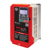
Magnetek Impulse VG+ series 4 Technical Manual (256 pages)
Adjustable Frequency/Vector Crane Controls
Brand:
Magnetek
| Category:
Controller
| Size: 5 MB
Table of Contents
Table of Contents
5
Introduction
10
How to Use this Manual
11
General Information
12
Assessing the System Requirements
12
Assessing the VFD Environment
12
Specifications
13
AC Reactor Specifications
16
S4IF Interface Board Specifications
18
S4I and S4IO Option Card Specifications
18
Installation
19
Choosing a Location
19
System Components
20
Standard Components
20
Optional VFD Components
20
As-Required VFD Components
20
Required Control Components
20
Long-Time Storage and Capacitor Reforming Procedure
21
Capacitor Storage and Reforming Process
21
Capacitor Reforming Procedure
21
Installation Orientation
23
Installing the VFD (Recommended Clearances)
23
Installing the VFD (Side-By-Side)
24
VFD Derating Data
25
Temperature Derating
25
Ip00/Open-Chassis Enclosure
25
Side-By-Side Mounting
25
Altitude Derating
25
Dimensions (Ip00/Open Chassis)
26
Wiring
30
Wiring Practices
30
Suggested Circuit Protection and Wire Size
33
Power Circuit Wiring
36
Main Circuit Connection Diagram
37
Terminal Block Configuration
40
Grounding
42
Insulation Barrier
43
Interface Board (S4IF)
44
DIP Switches and Jumper Locations
44
DIP Switch Functions
45
Sinking/Sourcing Mode for Safe Disable Inputs
45
Control Circuit Terminals
46
Interface Board (S4IF) Terminal Diagrams
47
Safe Torque off
48
Wiring the Encoder Circuit
49
Encoder Circuit Wiring Procedures
49
Encoder Wiring Diagrams and Information
50
Getting Started
51
Overview
51
Checks before Powering
51
Precautions
51
Using the Keypad
51
Keypad LED and Button Functions
52
Parameters
53
Parameter Modes
53
Operation Mode
53
Programming Mode
53
Auto-Tuning Mode
53
Modified Parameters Mode
53
Menu Structure
54
Initialization Setup
56
Parameter Access Level (A01-01)
56
Control Method (A01-02)
56
X-Press Programming
57
Motion (A01-03)
57
Speed Reference (A01-04)
57
Parameters Changed by X-Press Programming
59
Initialize Parameters (A01-05)
62
Password Entry (A01-06)
62
User Parameters (A02-01 through 32)
63
Auto-Tuning
64
Standard Auto-Tune (T01-01 = 0)
65
Non-Rotational Auto-Tune (T01-01 = 1)
66
Terminal Resistance Auto-Tune (T01-01 = 2)
66
Non-Rotational 2 Auto-Tune (T01-01 = 4)
67
Programming Advanced Features
68
Speed Parameters
68
Speed References
68
Reference Limits
70
Run/Reference Source
71
Stop Method
72
Decel to Stop (B03-03=0)
72
Coast to Stop (B03-03=1)
73
Decel W/Timer (B03-03=4)
73
Motor Rotation Change
74
Zero-Speed Operation
74
Input Scan Time
74
Run Select
75
Acceleration/Deceleration
77
Accel/Decel Time Switching Frequency
78
Jump Frequencies
79
Field Forcing
80
Special Functions
81
Quick Stop
82
Reverse Plug Simulation
83
Micro-Speed
84
End of Travel Limits
85
Phantom Stop
86
Load Sharing/Torque Following
86
Load Sharing Setup Example
87
Klixon
87
Hook Height Measurement
88
Electronic Programmable Limit Switches (EPLS)
89
Lower Limit/Upper Limit Bypass MFDI
90
Load Float
92
Load Check II
92
V/F Operation (A01-02 = 00)
92
OLV and FLV Operation (A01-02 = 02 and 03)
92
Load Check II Set up (C05-01 = 09)
93
Clearing a Load Check Alarm (LC)
94
Swift-Lift™ & Ultra-Lift
95
Swift-Lift
95
Ultra-Lift
95
Adaptive Ultra-Lift
95
Configuring the Swift-Lift & Ultra-Lift Function
97
Torque Limit
98
Anti-Shock
100
Load Brake Hoist (VG+)
102
Emergency Lift (VG+)
106
Emergency Lift Setup Instructions
106
Digital Input (DI-A3, S4I, or S4IO) Option Card Setup
108
Weight Measurement
109
System Tare and Calibration for Weight Measurement
110
Setting up U01-29 to Display Actual Weight
110
Weight Measurement Design Considerations
110
Slack Cable Detection
111
Snap Shaft Detection
112
Set up
112
Brake Delay Timers
113
Timer Function
113
Maintenance Timer
114
Load Share
114
Inch Control
115
Index Control
116
Tuning
118
DC Injection
118
Motor Slip Compensation
119
Torque Compensation
119
Automatic Speed Regulator (ASR) Tuning
120
Adjusting the ASR Parameters in FLV
121
Solving Problems During ASR Setup
121
Flux Vector (FLV)
122
Torque Control
123
Speed/Torque Control Switching
124
Dwell
125
S-Curve Acceleration/Deceleration
126
Carrier Frequency
127
Hunting Prevention
128
Motor Parameters
129
Voltage/Frequency Pattern
129
Motor Setup
135
Test Mode Configuration
136
Option Card Parameters
137
Encoder Feedback (PG-X3) Option Card Setup
137
Analog Input (AI-A3) Option Card Setup
139
Analog Output (AO-A3) Option Card Setup
139
Digital Output (DO-A3 or S4IO) Option Card Setup
141
Profibus-DP (SI-P3) Option Card Setup
143
Ethernet/Ip (SI-EN3) and Modbus TCP/IP (SI-EM3) Option Card Setup
145
Terminal Parameters
147
Digital Inputs
147
F1 and F2 Keys Function Selection
150
Digital Outputs
151
Digital Outputs-Alarm/Fault Annunciate (H02-01-03=40)
155
External Fault Response Selection
157
Analog Inputs
158
Analog Outputs
161
Serial Communication Setup
163
Pulse Train Input/Output
165
Protection Parameters
166
Motor Overload
166
Power Loss Ride Thru
167
Stall Prevention
168
Speed Agree
169
Test Mode
171
Torque Detection
171
Hardware Protection
175
Automatic Fault Reset
177
Fault Latch Selection
179
Keypad Parameters
180
Monitor Selection
180
Keypad Key Selection
183
Maintenance History
186
Copy Function
187
Monitor Parameters
189
Troubleshooting
196
Troubleshooting the VFD
196
Maintenance and Inspection
196
Troubleshooting Encoder Related Faults
210
Fault Code: DEV-Speed Deviation Fault
210
Definition
210
Corrective Action
210
Fault Code: PGO-X-S/PGO-X-H-Pulse Generator Signal Fault
211
Definition
211
Corrective Action
211
Fault Code: BE1-Rollback Fault
212
Definition
212
Correction Action
212
Fault Code: BE2-Torque Proving Fault
212
Corrective Action
212
Fault Code: BE3-Brake Release Fault
213
Definition
213
Corrective Action
213
Alarm Code: BE6-Brake Proving Alarm
214
Definition
214
Corrective Action
214
Alarm Code: BE8-Brake Slipping Alarm
215
Definition
215
Corrective Action
215
Fault Code: OC-Over Current Fault
216
Definition
216
Corrective Action
216
Fault Display and Corrective Actions at Auto-Tuning
217
Troubleshooting Option Card Related Faults
219
VFD-Side Error Codes
219
Copy Function Related Faults
222
Tasks, Errors, and Troubleshooting
222
Power Section Check
223
Power off Checks
223
S4IF Replacement Procedure
225
Advertisement
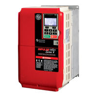
Magnetek Impulse VG+ series 4 Instruction Manual (276 pages)
Adjustable Frequency Crane Controls
Brand:
Magnetek
| Category:
Controller
| Size: 4 MB
Table of Contents
Product Safety Information
3
DANGER, WARNING, CAUTION, and NOTE Statements
4
Service Information
5
Table of Contents
7
Chapter 1: Introduction
13
How to Use this Manual
16
Introduction
17
Assessing the System Requirements
17
Assessing the Drive Environment
17
IMPULSE®•G+ & VG+ Series 4 General Specifications
18
AC Reactor Specifications
20
S4IF Interface Specifications
24
S4I and S4IO Option Specifications
24
Chapter 2: Installation
27
IMPULSE®•G+ & VG+ Series 4 System Components and External Devices
30
Long Time Storage
31
Installing the Drive
33
Multiple Drive Installation (Side-By-Side Installation)
35
Drive Derating Data
36
Temperature Derating
36
Dimensions for Ip00/Open Chassis Enclosures
36
Chapter 3: Wiring
41
IMPULSE®•G+ & VG+ Series 4 Wiring Practices
43
Suggested Circuit Protection Specifications and Wire Size
46
Power Circuit Wiring Procedures
49
Main Circuit Connection Diagram
50
Terminal Block Configuration
53
Insulation Barrier
55
Grounding
55
Interface Circuit Board
57
S4IF DIP Switches and Jumper
57
Dip Switches
58
Sinking/Sourcing Mode Selection for Safe Disable Inputs
59
Control Circuit Terminals
60
S4IF Control Circuit Terminal Diagrams
61
Safe Torque off
62
Wiring the Encoder Circuit
64
Encoder Circuit Wiring Procedures
64
Encoder Wiring Diagrams and Information
65
Chapter 4: Getting Started
67
Overview
69
Checks before Powering
69
Precautions
69
Using the Keypad
70
Keypad LED and Button Functions
71
Parameters
72
Parameter Modes
73
Initialization Set-Up
75
Parameter Access Level (A01-01)
75
Control Method Selection (A01-02)
75
X-Press Programming
76
Motion (A01-03)
76
Speed Reference (A01-04)
76
Initialize Parameters (A01-05)
81
Password Entry (A01-06)
81
User Parameters (A02-01 through 32)
82
Auto-Tuning
83
Standard Auto-Tune (T01-01 = 0) Instructions
84
Non-Rotational Auto-Tune (T01-01 = 1) Instructions
85
Terminal Resistance Auto-Tune (T01-01 = 2) Instructions
86
Non-Rotational 2 Auto-Tune (T01-01 = 4) Instructions
86
Chapter 5: Programming Advanced Features
87
Introduction
89
Application
89
Preset Reference
89
Reference Limits
91
Sequence/Reference Source
92
Stop Method
93
Decel to Stop (B03-03=0)
93
Coast to Stop (B03-03=1)
94
Decel W/Timer (B03-03=4)
94
Motor Rotation Change
95
Zero-Speed Operation
95
Input Scan Time
95
LO/RE Run Select
95
Acceleration/Deceleration
98
Accel/Decel Time Switching Frequency
99
Jump Frequencies
99
Special Functions
101
Quick Stop
102
Reverse Plug Simulation
103
Micro-Speed
104
End of Travel Limits
105
Phantom Stop
106
Load Sharing/Torque Following - 2 or more Mechanically Coupled Motors
106
Klixon
107
Hook Height Measurement
108
Electronic Programmable Limit Switches (EPLS)
109
Lower Limit/Upper Limit Bypass MFDI
110
Load Float
112
Load Check II
112
V/F Operation (A01-02 = 00)
112
OLV and FLV Operation (A01-02 = 02 and 03)
113
Load Check II Set up (C05-01 = 09)
113
Swift-Lift™ & Ultra-Lift
116
Swift-Lift
116
Ultra-Lift
116
Adaptive Ultra-Lift
116
Configuring the Swift-Lift & Ultra-Lift Function
118
Torque Limit
119
Anti-Shock
121
No-Load Brake Hoist (VG+)
123
E-Lift (VG+)
127
Digital Input Option Set-Up (DI-A3 and S4IO)
129
Weight Measurement
130
System Tare and Calibration for Weight Measurement
131
Setting up U01-29 to Display Actual Weight
131
Weight Measurement Design Considerations
131
Slack Cable Detection
132
Snap Shaft Detection
134
Brake Delay Timers
135
Timer Function
135
Maintenance Timer
136
Inching Control
137
Index Function
138
Tuning
141
DC Injection
141
Motor Slip Compensation
142
Torque Compensation
142
Automatic Speed Regulator (ASR) Tuning
143
Torque Control
147
Speed/Torque Control Switching
148
S-Curve Acceleration/Deceleration
151
Carrier Frequency
152
Hunting Prevention
153
Motor Parameters
154
Voltage/Frequency Pattern
154
Motor Set-Up
159
Test Mode Configuration
160
Option Card Parameters
161
Encoder (PG) Option Set-Up
161
Analog Input (AI-A3) Option Set-Up
164
Analog Output (AO-A3) Option Set-Up
165
Digital Output (DO-A3) and S4IO Option Set-Up
166
Profibus-DP Communication Option Card Set-Up
168
Ethernet Option Card Set-Up (Ethernet IP & Modbus TCP/IP)
170
Terminal Parameters
172
Digital Inputs
172
F1 and F2 Keys Function Selection
175
Digital Outputs
176
Digital Outputs-Alarm/Fault Annunciate (H02-01-03=40)
180
Analog Inputs
183
Analog Outputs
186
Serial Communication Set-Up
188
Pulse Train Input/Output
190
Protection Parameters
191
Motor Overload
191
Power Loss Ride Thru
192
Stall Prevention
193
Speed Agree
195
Test Mode
197
Torque Detection
198
Hardware Protection
201
Automatic Fault Reset
204
Fault Latch Selection
206
Operator Parameters
207
Monitor Selection
207
Keypad Key Selection
210
Maintenance History
213
Copy Function
214
Monitor Parameters
217
Chapter 6: Troubleshooting
223
Troubleshooting the Drive
225
Maintenance and Inspection
225
Troubleshooting Encoder Related Faults
238
Fault Code: DEV- Speed Deviation Fault
238
Fault Code: PGO-X-S/PGO-X-H-Pulse Generator Signal Fault
239
Fault Code: BE1-Rollback Fault
240
Fault Code: BE2-Torque Proving Fault
240
Fault Code: BE3-Brake Release Fault
241
Alarm Code: BE6-Brake Proving Alarm
242
Alarm Code: BE8-Brake Slipping Alarm
242
Fault Code: OC-Over Current Fault
244
Fault Display and Corrective Actions at Auto-Tuning
245
Troubleshooting Option Card Related Faults
247
Drive-Side Error Codes
247
Copy Function Related Faults
250
Tasks, Errors, and Troubleshooting
250
Power Section Check
252
S4IF Replacement Procedure
253
Magnetek Impulse VG+ series 4 Technical Manual (248 pages)
Adjustable Frequency/Vector Crane Controls
Brand:
Magnetek
| Category:
DC Drives
| Size: 6 MB
Table of Contents
Table of Contents
5
Introduction
8
How to Use this Manual
9
General Information
10
Assessing the System Requirements
10
Assessing the VFD Environment
10
Specifications
11
VFD Specifications
11
AC Reactor Specifications
14
Interface Board (S4IF) Specifications
16
S4I and S4IO Option Card Specifications
16
Installation
17
Environmental Requirements
17
System Components
18
Standard Components
18
Optional Components
18
As-Required Components
18
Required Control Components
18
Long-Term Storage and Capacitor Reforming
19
Capacitor Reforming Procedure
19
Installation Orientation
21
Recommended Installation Clearances
21
Optional Side-By-Side Installation
22
VFD Derating
23
Temperature Derating
23
Altitude Derating
23
Dimensions (Ip00/Open-Chassis)
24
Wiring
28
Wiring Practices
28
Suggested Circuit Protection and Wire Size
31
Power Circuit Wiring
34
Power Circuit Connection Diagrams
35
Power Circuit Terminal Block Diagrams
38
Insulation Barrier
40
Grounding
41
Interface Board (S4IF)
42
Terminal Block, DIP Switch, and Jumper Diagrams
42
DIP Switch Functions
43
Sinking/Sourcing Mode for Safe Disable Inputs
43
Control Circuit Wiring
44
Control Circuit Terminal Block Diagrams
45
Sinking/Sourcing for Digital Inputs (24 VDC Only)
46
Safe Disable and Safe Torque off
47
Encoder Circuit
48
Encoder Circuit Specification and Wiring Procedure
48
Encoder Wiring Diagram
49
Getting Started
50
Overview
50
Checks before Powering
50
Precautions
50
Using the Keypad
50
Keypad LED and Button Functions
51
Parameters
52
Parameter Menus
52
Menu Structure
53
Initial Setup
55
Auto-Tuning
63
Standard Auto-Tune (T01-01 = 0)
64
Non-Rotational 1 Auto-Tune (T01-01 = 1)
64
Terminal Resistance Auto-Tune (T01-01 = 2)
65
Non-Rotational 2 Auto-Tune (T01-01 = 4)
65
Programming Advanced Features
66
Speed Parameters
66
Speed References
66
Reference Limits
68
Run/Reference Source
69
Stop Method
70
Motor Rotation Change
72
Zero-Speed Operation
72
Input Scan Time
72
Run Select
73
Acceleration/Deceleration
75
Accel/Decel Time Switching Frequency
76
Jump Frequencies
77
Field Forcing
77
Special Functions
78
Quick Stop
79
Reverse Plug Simulation
80
Micro-Speed
81
End of Travel Limits
82
Phantom Stop
82
Load Share (Torque Following)
83
Klixon
83
Hook Height Measurement
84
Electronic Programmable Limit Switches (EPLS)
85
Upper/Lower Limit Bypass
86
Load Float 2
88
Load Check II
88
Swift-Lift™ & Ultra-Lift
91
Torque Limit
94
Anti-Shock
96
Load Brake Hoist
98
Emergency Lift
102
Digital Input (DI-A3, S4I, or S4IO) Option Card Setup
104
Weight Measurement
105
Slack Cable Detection
107
Snap Shaft Detection
108
Brake Delay Timers
109
Timer Function
109
Maintenance Timer
110
Load Share
110
Inch Control
111
Index Control
112
Tuning
114
DC Injection Braking
114
Motor Slip Compensation
115
Torque Compensation
115
Automatic Speed Regulator (ASR) Tuning
116
Torque Control
119
Dwell
121
S-Curve Acceleration/Deceleration
122
Carrier Frequency
123
Hunting Prevention
124
Motor Parameters
125
Voltage/Frequency (V/F) Pattern
125
Motor Setup
130
Test Mode Configuration
131
Option Card Parameters
132
Encoder Feedback (PG-X3) Option Card Setup
132
Analog Input (AI-A3) Option Card Setup
134
Analog Output (AO-A3) Option Card Setup
134
Digital Output (DO-A3 or S4IO) Option Card Setup
136
Profibus-DP (SI-P3) Option Card Setup
138
Ethernet/Ip (SI-EN3), PROFINET (SI-EP3), and Modbus TCP/IP (SI-EM3) Option Card Setup
140
Control I/O Parameters
141
Digital Inputs
141
F1 and F2 Keys Function Selection
145
Digital Outputs
146
Analog Inputs
152
Analog Outputs
155
Serial Communication
157
Pulse Train Input/Output
159
Protection Parameters
160
Motor Overload
160
Power Loss Ride Thru
161
Stall Prevention
162
Speed Agree
163
Test Mode
165
Torque Detection
165
Hardware Protection
169
Automatic Fault Reset
171
Fault Latch
173
Keypad and VFD Configuration
174
Monitor Selection
174
VFD and Keypad Selection
177
Maintenance History
180
Copy Function
181
Monitors
183
Troubleshooting
190
Troubleshooting the VFD
190
Maintenance and Inspection
190
Troubleshooting Encoder and Brake Faults and Alarms
204
DEV-Speed Deviation Fault
204
PGO-X-S/PGO-X-H-Pulse Generator Signal Fault
205
BE1-Rollback Fault
206
BE2-Torque Proving Fault
206
BE3-Brake Release Fault
207
BE6-Brake Proving Alarm
208
BE8-Brake Slipping Alarm
209
OC-Over Current Fault
209
Auto-Tuning Errors
210
Option Card Faults
212
Copy Function Errors
215
Power Section Check
216
Interface Board (S4IF) Replacement Procedure
217
Appendix A: Parameter Listing
219
Appendix B: Standards Compliance
238
Advertisement
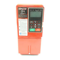
Magnetek Impulse VG+ series 4 Product Manual (54 pages)
Impulse G+ & VG+ Series 3 to series 4
Brand:
Magnetek
| Category:
Controller
| Size: 2 MB
Table of Contents
Table of Contents
3
Overview
4
Drive Replacement Checklist
4
Ratings Summary
6
Rated Drive Model
7
Digital Operator Comparison
8
Terminals
9
Main Circuit Terminals
9
Control Circuit Terminals
10
Terminal Size and Wire Gauge Comparison
12
Dimensions, Installation Space and Substitution Material
25
Drive Dimension Comparison
25
IMPULSE ® G+/VG+ Series 4 Drive Options
27
Parameter Cross Reference
31
IMPULSE®•G+ & VG+ Series 3 to Series 4 Transition Guide August
32
Magnetek Impulse VG+ series 4 Installation Manual (23 pages)
Analog Monitor
Brand:
Magnetek
| Category:
Monitor
| Size: 1 MB
Table of Contents
Preface and Safety
2
Applicable Documentation
2
Registered Trademarks
3
General Safety
4
General Precautions
4
Product Overview
5
About this Product
5
Option Package Contents
6
Tools Required for Installation
6
Option Components
7
Terminal Block TB1
7
Installation Procedure
8
Section Safety
8
Installing the Option
11
Crimp Terminals
18
Terminal Functions
18
Related Parameters
19
Troubleshooting
20
Drive-Side Error Codes
20
Interface Circuit
21
Specifications
22
Magnetek Impulse VG+ series 4 Quick Start Manual (3 pages)
Variable Frequency Drive
Brand:
Magnetek
| Category:
DC Drives
| Size: 2 MB
Advertisement
Related Products
Magnetek IMPULSE VG+ Series 3
Magnetek 2001-G+M
Magnetek 2003-G+M
Magnetek 2005-G+M
Magnetek 2008-G+M
Magnetek 2011-G+M
Magnetek 2017-G+M
Magnetek 2025-G+M
Magnetek 2033-G+M
Magnetek 2047-G+M
Magnetek Categories
Remote Control
Controller
Transmitter
DC Drives
Receiver
More Magnetek Manuals
Login
Sign In
OR
Sign in with Facebook
Sign in with Google
Upload manual
Upload from disk
Upload from URL