Magnetek IMPULSE G+ 4 Series Quick Start Manual
Variable frequency drive
Hide thumbs
Also See for IMPULSE G+ 4 Series:
- Instruction manual (276 pages) ,
- Technical manual (256 pages) ,
- Installation manual (23 pages)
Advertisement
Quick Links
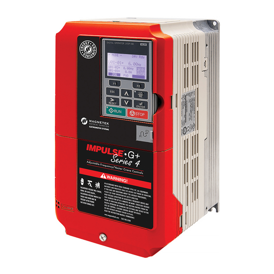
IMPULSE
•G+/VG+ Series 4 Variable Frequency Drive
®
Quick Start Guide
OVERVIEW
The following procedure is a supplement to other documentation
available for the IMPULSE•G+/VG+ Series 4 variable frequency
drive (VFD). This will guide the user in proper installation and setup
of the system.
Before using the VFD-controlled equipment, the operator shall
read the operating manual of the hoisting machine, shall be
trained, and has to know all hazards by operating of cranes, hoists,
or lifting devices.
DANGER! DANGEROUS VOLTAGES ARE PRESENT
WHEN VFD IS ON. Improper wiring can cause bodily
harm and damage to the equipment. Before applying
power to the IMPULSE•G+/VG+ Series 4, ensure that all
protective covers are fastened and all wiring connec-
tions are secure. After power has been turned OFF, wait
at least 5 minutes until the charge indicator extin-
guishes completely before touching any wiring, circuit
boards, or components.
When installing the system, be sure to follow good wiring practices
and all applicable codes. Ensure that the mounting of components
is secure and that the environment, such as extreme dampness,
poor ventilation, etc., will not cause system degradation.
Read this document thoroughly before attempting installation.
Refer to the technical manual available at:
www.columbusmckinnon.com/magnetek.
Step 1
Connect Motor and Line Power
The following figure shows the electrical connections for the input
power and motor terminals on IMPULSE•G+/VG+ Series 4 VFD.
Make the appropriate connections with power turned off. Follow
good wiring practices and follow all applicable electrical codes.
Ensure the equipment is properly grounded, as shown.
WARNING: DO NOT CONNECT ANY OF THE FOLLOWING
TERMINALS TO EARTH GROUND.
WARNING DO NOT CONNECT ANY OF THE
FOLLOWING TERMINALS TO EARTH GROUND
-
B1
B2
+1
+2
+3
DC Bus terminals
location varies by
model.
(W/T3)
(T/L3)
(U/T1)
(V/T2)
(S/L2)
(R/L1)
To change
direction of
Connect to
motor rotation
chassis ground
swap any two
Input
of the three
Protection
motor leads
(Fuse or Circuit
(See Step 2)
Breaker)
L1 L2 L3
Connect
frame to
ground
Use L1, L2 for
Use L1, L2, L3 for
3Ø Induction
*
1Ø Input Power
3Ø Input Power
motor
N49 W13650 Campbell Drive
Menomonee Falls, WI 53051
Phone: 262.783.3500
Fax: 262.783.3510
Toll-Free Phone: 800.288.8178
Toll-Free Fax: 800.298.3503
Step 2
Typical Connection Diagram
This step shows a typical wiring diagram and connection points for the IMPULSE•G+/VG+
Series 4 VFD. Wiring connections should only be made by trained and authorized
personnel when power to the VFD is turned off.
Dynamic Braking**
Inputs
Branch
Circuit
Protec on &
Line Reactor
+1
+2
+3
Disconnect
(Op onal)
L1
R/L1
3-Phase
L2
S/L2
Power Supply
50/60Hz
L3
T/L3
X2 Common***
X1
X2
X2 Common***
120 VAC*
X2 Common***
24 VAC*
42-48 VAC*
X2 Common***
S1 MFDI 1
ULS2
FWD/UP
S2 MFDI 2
LLS2
REV/DOWN
S3 MFDI 3
SPEED 2
S4 MFDI 4
SPEED 3
S5 MFDI 5
SPEED 4
S6 MFDI 6
SPEED 5
S7 MFDI 7
MICROSPEED
S8 MFDI 8
EXT FAULT
E(G)
+V +10.5 VDC +/-10%, 20mA
-V -10.5 VDC +/-10%, 20 mA
2kΩ
A1 Mul -Func on Analog Input 1
-10 to +10 VDC, 0 to +10 VDC (20kΩ)
A2 Mul -Func on Analog Input 2
-10 to +10 VDC, 0 to +10 VDC (20kΩ)
4 to 20 mA (250Ω)
A3 Mul -func on Analog Input 3
-10 to +10 VDC, 0 to +10 VDC (20kΩ) PTC
RP Mul -func on Pulse Input
0 to 32 kHz
AC
Termina ng
Resistor
DIP Switch S2
120Ω
R+
Modbus RTU
Mul -Func on Analog Output 1 FM
R-
Communica ons
RS-485/422
S+
Mul -Func on Analog Output 2 AM
115.2 kbps Max.
S-
IG
Mul -Func on Pulse Train Output MP
H2
H1
Safety Controller
(Op onal)
HC
*
Requires op onal 120 VAC, 42-48 VAC, or 24 VAC interface board. 24 VDC is also available.
** Set L08-55 to 0 when using an external dynamic braking op on.
Resistor is connected to B1 and B2. CDBR is connected to – and +3.
*** 24VDC interface board has terminals SN, SC, and SP instead of X2.
For questions regarding service or technical information contact:
1.833.SVC.CMCO (1.833.782.2626)
International Service
Outside the U.S. & Canada call 1.262.783.3500, press 3
Outputs
Load Reactor
-
B1
B2
(Op onal)
Motor
U/T1
T1
V/T2
T2
IM
T3
W/T3
A+
A-
B+
PG
B-
Z+
Z-
IP
IG
FE
a+
a-
b+
b-
z+
z-
X1A X1
X2
MA
MB
MC
M0
M1
M2
Brake Contactor
M3
M5
Brake Contactor
M6
Alarm Contactor
E(G)
Mul -Func on
+
-
Analog Outputs 1-2
0 to +/-10 VDC, 2mA
+
-
4-20 mA (FM only)
Mul -Func on Pulse Output
0 to 32kHz, 9 VDC @ 3kΩ
+/-5% Accuracy
AC
Safety Electronic Device Monitor
DM+
DM-
Step 3
PG-X3 Encoder Feedback Card and Encoder Wiring
(IMPULSE•VG+ Series 4 Only)
In this step the PG-X3 encoder feedback card is installed. WITH POWER OFF,
install the PG-X3 card as shown below. Make sure to follow good wiring
practices and follow all applicable codes. Ensure that the feedback card is
grounded properly as shown in item H below.
Option Card Installation
This option card can be inserted into the CN5-C (top) connector located on the
drive's control board.
Ground Lead
A – Terminal block TB1
B – Ground terminal (installation hole)
C – Jumper for PG power supply voltage (CN3)
D – Terminal block TB2
PG-X3 Option Card
E – Model number
F – Installation hole
G – Connector (CN5)
Encoder Power Supply
Encoder Connection
(Max. 200mA)
It is required to use a differential quadrature
Select Encoder Power
encoder in Flux Vector control mode
Supply (IP + IG TB2)
(A01-02 = 3).
with Jumper CN3.
Default
IMPORTANT: Verify Encoder
Encoder
Power Supply Rating
Power
+
(Required for Flux Vector Operation)
PG-X3 Encoder Wiring
www.columbusmckinnon.com/magnetek
IMPULSE•G+/VG+ Series 4 Quick Start Guide
August 2020 © Copyright 2020 Magnetek
A – Connector CN5-C
B – Connector CN5-B
C – Connector CN5-A
D – Drive grounding terminal (FE)
E – Insert connector CN5 here
F – Option card
G – Mounting screw
H – Lead line ground
I – Use wire cutters to create an
opening for cable lines
J – Front cover
K – Digital operator
L – Terminal cover
TB2
PG-X3 Terminals
IP
IG
SG
a+ a-
b+
b- z+
z+
TB1
A+
A-
B+
B-
Z+ Z-
SD FE
-
Encoder Signals
PG
144-27514 R1
Advertisement

Related Manuals for Magnetek IMPULSE G+ 4 Series


Summary of Contents for Magnetek IMPULSE G+ 4 Series
- Page 1 Menomonee Falls, WI 53051 1.833.SVC.CMCO (1.833.782.2626) IMPULSE•G+/VG+ Series 4 Quick Start Guide Phone: 262.783.3500 144-27514 R1 Fax: 262.783.3510 International Service August 2020 © Copyright 2020 Magnetek Toll-Free Phone: 800.288.8178 Outside the U.S. & Canada call 1.262.783.3500, press 3 Toll-Free Fax: 800.298.3503...
- Page 2 Menomonee Falls, WI 53051 1.833.SVC.CMCO (1.833.782.2626) IMPULSE•G+/VG+ Series 4 Quick Start Guide Phone: 262.783.3500 144-27514 R1 Fax: 262.783.3510 International Service August 2020 © Copyright 2020 Magnetek Toll-Free Phone: 800.288.8178 Outside the U.S. & Canada call 1.262.783.3500, press 3 Toll-Free Fax: 800.298.3503...
- Page 3 Menomonee Falls, WI 53051 1.833.SVC.CMCO (1.833.782.2626) IMPULSE•G+/VG+ Series 4 Quick Start Guide Phone: 262.783.3500 144-27514 R1 Fax: 262.783.3510 International Service August 2020 © Copyright 2020 Magnetek Toll-Free Phone: 800.288.8178 Outside the U.S. & Canada call 1.262.783.3500, press 3 Toll-Free Fax: 800.298.3503...
Need help?
Do you have a question about the IMPULSE G+ 4 Series and is the answer not in the manual?
Questions and answers