Sign In
Upload
Manuals
Brands
Juniper Manuals
Network Router
EX4600
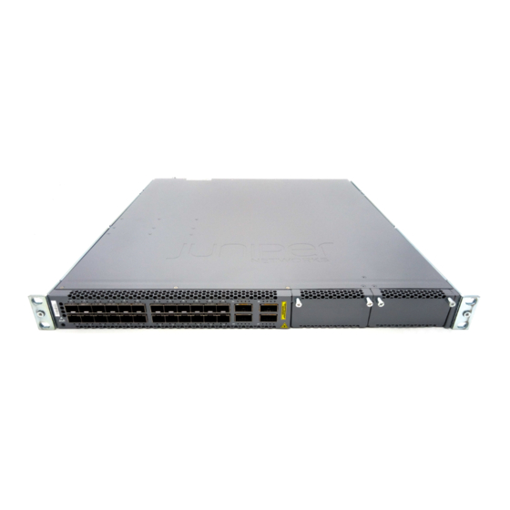
Juniper EX4600 Manuals
Manuals and User Guides for Juniper EX4600. We have
5
Juniper EX4600 manuals available for free PDF download: Hardware Manual, Quick Start Manual
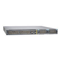
Juniper EX4600 Hardware Manual (230 pages)
Brand:
Juniper
| Category:
Switch
| Size: 4 MB
Table of Contents
Table of Contents
3
About the Documentation
13
Documentation and Release Notes
13
Supported Platforms
13
Documentation Conventions
13
Table 1: Notice Icons
14
Table 2: Text and Syntax Conventions
14
Documentation Feedback
15
About the Documentation
15
Requesting Technical Support
16
Self-Help Online Tools and Resources
16
Opening a Case with JTAC
16
Overview
19
EX4600 Overview
19
Cooling System and Airflow
19
Modules
19
Power Supply
19
Chapter 1 EX4600 Overview
21
EX4600 Switch Hardware Overview
21
EX4600 Hardware
21
Figure 1: QFX-EM-4Q Expansion Module
22
Figure 2: EX4600-EM-8F Expansion Module
22
System Software
23
EX4600 Switch Models
23
EX4600 Overview
23
Table 3: EX4600 Switch Product Numbers
23
Field-Replaceable Units in an EX4600 Switch
24
Table 4: Frus in a EX4600 Switch
24
Functionality
25
Power Supply
25
Chapter 2 Chassis
27
Chassis Physical Specifications for a EX4600 Switch
27
Management Panel of an EX4600 Switch
27
Table 5: Physical Specifications for the EX4600 Switch Chassis
27
Figure 3: EX4600 Switch, FRU End
28
Figure 4: Management Panel Components
28
Port Panel of an EX4600 Switch
29
Chassis
29
Cooling System and Airflow
29
Figure 5: EX4600 Switch Port Panel
30
Chapter 3 Cooling System and Airflow
31
Cooling System and Airflow in an EX4600 Switch
31
Fan Modules
31
Figure 6: Fan Module for EX4600 Switches
32
Table 6: Fan Modules for EX4600 Switches
32
Figure 7: Air in Airflow through EX4600 Switch Chassis
33
Figure 8: Air out Airflow through EX4600 Switch Chassis
34
Switch
34
Fan Module Status
35
Table 7: Fan Module LED
35
Chapter 4 Modules
37
Expansion Modules for the EX4600
37
Ex4600-Em-8F
37
Qfx-Em-4Q
38
Figure 9: EX4600-EM-8F Faceplate and Leds
38
Figure 10: QFX-EM-4Q Faceplate and Leds
38
Table 8: EX4600-EM-8F Status LED
38
Table 9: Expansion Module Status LED
39
Chapter 5 Power Supply
41
AC Power Supply in an EX4600 Switch
41
Figure 11: AC Power Supply in EX4600 Switches
41
Figure 12: Power Supply Handle Detail
42
Table 10: Airflow Direction in EX4600 and QFX5100 AC Power Supplies
42
DC Power Supply in an EX4600 Switch
43
Figure 13: DC Power Supply in EX4600 and QFX5100 Switches
43
Grounding Cable and Lug Specifications for an EX4600 Switch
44
Figure 14: DC Power Supply Faceplate in EX4600 Switches
44
Planning
47
Port and Interface Specifications
47
Rack and Cabinet Requirements
47
Site Preparation
47
Chapter 6 Site Preparation
49
Site Preparation Checklist for an EX4600 Switch
49
Table 11: Site Preparation Checklist
49
General Site Guidelines
50
Site Electrical Wiring Guidelines
51
Table 12: Site Electrical Wiring Guidelines
51
Environmental Requirements and Specifications for EX Series Switches
51
Table
51
Environmental Requirements and Specifications for EX Series Switches
53
Table 13: EX Series Switch Environmental Tolerances
53
Chapter 7 Rack and Cabinet Requirements
57
Rack Requirements for an EX4600 Switch
57
Table 14: Rack Requirements for the EX4600 Switch
57
EX4600 Switch
57
Switch
57
Cabinet Requirements for an EX4600 Switch
58
Clearance Requirements for Airflow and Hardware Maintenance for an EX4600 Switch
58
Switch
58
Rack and Cabinet Requirements
59
Table 15: Cabinet Requirements for the EX4600 Switch
59
Figure 15: Clearance Requirements for Airflow and Hardware Maintenance for
60
Chapter 8 Port and Interface Specifications
61
USB Port Specifications for an EX Series Switch
61
Ex4600
61
Table 16: Cable Specifications for Console and Management Connections for the QFX Series
62
Console Port Connector Pinout Information for an EX Series Switch
63
Table 17: EX Series Switches Console Port Connector Pinout Information
63
Interface Support for an EX4600 Switch
64
Figure 16: Port Panel of EX4600
64
Table 18: Supported Optical Transceivers for the EX4600 Switch
64
Table 19: Supported DAC and DAC Breakout Cables for the EX4600 Switch
65
Switch
67
Table 20: Copper Interface Support and Optical Interface Support for Gigabit Ethernet SFP Transceivers for the EX4600 Switch
68
Table 21: Optical Interface Support for 10-Gigabit Ethernet SFP+ Transceivers
71
Table 22: Interface Support for 40-Gigabit Ethernet QSFP+ Transceivers for the
76
Interface Specifications for SFP+ DAC Cables for the EX4600 Switch
78
Table 23: SFP+ Passive Direct Attach Copper Cable Specifications
79
Table 24: SFP+ Active Direct Attach Copper Cable Specifications
81
Switch
83
Table 25: QSFP+ DAC Passive Breakout Cable Specifications
84
Table 26: QSFP+ Active DAC Breakout Cable Specifications
85
Interface Specifications for QSFP+ DAC Cables for the EX4600 Switch
86
Table 27: Interface Specifications for Passive Copper QSFP+ DAC Cables
87
Table 28: Interface Specifications for Active Copper QSFP+ DAC Cables
89
Chapter 9 Cable Specifications
91
Network Cable Specifications for EX4600 Switches
91
Cable Specifications for Console and Management Connections for the EX4600
91
Table 29: Cable Specifications for Switch-To-Management-Device
91
And Dispersion
92
Signal Loss in Multimode and Single-Mode Fiber-Optic Cable
92
Table 30: Cable Specifications for Console and Management Connections for
92
Attenuation and Dispersion in Fiber-Optic Cable
93
Calculating the EX Series Switch Fiber-Optic Cable Power Budget
94
Calculating the EX Series Switch Fiber-Optic Cable Power Margin
94
Table 31: Estimated Values for Factors Causing Link Loss
95
Chapter 10 Planning Power Requirements
97
AC Power Specifications for an EX4600 Switch
97
AC Power Cord Specifications for an EX4600 Switch
97
Table 32: AC Power Specifications for an EX4600 Switch
97
Table 33: AC Power Cord Specifications
98
DC Power Specifications for an EX4600 Switch
99
Table 34: DC Power Specifications for an EX4600 Switch
99
Chapter 11 Compliance
101
Agency Approvals for EX Series Switches
101
Compliance Statements for EMC Requirements for EX Series Switches
102
Canada
102
European Community
103
Israel
103
Japan
103
Korea
104
United States
104
FCC Part 15 Statement
104
Nonregulatory Environmental Standards
105
Declaration of Conformity for EX4600 Switch
106
Chapter 12 General Safety Information
109
General Safety Guidelines and Warnings
109
Definitions of Safety Warning Levels
110
Fire Safety Requirements
112
Qualified Personnel Warning
113
Warning Statement for Norway and Sweden
114
Chapter 13 Radiation and Laser Warnings
115
Radiation from Open Port Apertures Warning
115
Laser and LED Safety Guidelines and Warnings for EX Series Switches
116
General Laser Safety Guidelines
116
Class 1 Laser Product Warning
117
Class 1 LED Product Warning
117
Laser Beam Warning
118
Chapter 14 Installation and Maintenance Safety Information
121
Installation Instructions Warning
121
Chassis Lifting Guidelines for an EX4600 Switch
123
Installation Instructions Warning
123
Restricted Access Warning
124
Ramp Warning
125
Rack-Mounting and Cabinet-Mounting Warnings
126
Grounded Equipment Warning
126
Grounded Equipment Warning
130
Maintenance and Operational Safety Guidelines and Warnings
131
Battery Handling Warning
131
Jewelry Removal Warning
132
Lightning Activity Warning
133
Operating Temperature Warning
134
Product Disposal Warning
135
Chapter 15 Power and Electrical Safety Information
137
General Electrical Safety Guidelines and Warnings
137
Prevention of Electrostatic Discharge Damage
138
Figure 17: Place a Component into an Antistatic Bag
139
AC Power Electrical Safety Guidelines
140
AC Power Disconnection Warning
142
DC Power Electrical Safety Guidelines
143
DC Power Disconnection Warning
145
DC Power Grounding Requirements and Warning
147
DC Power Wiring Sequence Warning
148
DC Power Wiring Terminations Warning
149
Multiple Power Supplies Disconnection Warning
151
TN Power Warning
151
Action to Take after an Electrical Accident
152
Chapter 16 Installing the EX4600 Device
157
Installing and Connecting an EX4600 Switch
157
Unpacking an EX4600 Switch
158
Table 35: Inventory of Components Supplied with an EX4600 Switch
158
Mounting an EX4600 Switch in a Rack or Cabinet
159
Before You Begin Rack Installation
159
Four Post Procedure
160
Figure 18: Attaching Mounting Rails to the EX4600
161
Figure 19: Attach EX4600 Switch to Rack
161
Figure 20: Slide Mounting Blade into EX4600 Mounting Rail
162
Chapter 17 Connecting the EX4600 Device
163
Connecting Earth Ground to an EX4600 Switch
164
Connecting AC Power to an EX4600 Switch
165
Figure 21: Connecting a Grounding Cable to an EX4600 Switch
165
Connecting DC Power to an EX4600 Switch
167
Figure 22: Connecting an AC Power Cord to an AC Power Supply in an EX4600
167
Figure 23: DC Power Supply Faceplate for an EX4600 Switch
170
Connecting an EX Series Switch to a Management Console
171
Figure 24: Securing Ring Lugs to the Terminals on the EX4600 DC Power
171
Figure 25: Ethernet Cable Connector
171
Connecting an EX4600 Switch to a Network for Out-Of-Band Management
173
Figure 26: Connecting an EX Series Switch to a Management Console through
173
Figure 27: Connecting an EX Series Switch Directly to a Management
173
Connecting EX4600 Switches in a Virtual Chassis
174
Figure 28: Connecting an EX4600 Switch to a Network for Out-Of-Band
174
Figure 29: Four Member Virtual Chassis with EX4600 Master and Backup
175
Chapter 18 Performing Initial Configuration
177
Configuring an EX4600 Switch
177
Chapter 19 Removing the Device
181
Powering off an EX4600 Switch
181
Removing an EX4600 Switch from a Rack or Cabinet
183
Chapter 20 Replacing Components
185
Installing and Removing EX4600 Switch Hardware Components
185
Installing a Power Supply in an EX4600 Switch
186
Removing a Power Supply from an EX4600 Switch
187
Figure 30: Installing a Power Supply in an EX4600 Switch
187
Installing an Expansion Module in an EX4600 Switch
189
Figure 31: Removing a Power Supply from an EX4600 Switch
189
Figure 32: Installing a QFX4Q Expansion Module in an EX4600 Switch
190
Removing an Expansion Module from an EX4600 Switch
191
Installing a Fan Module in an EX4600 Switch
192
Figure 33: Removing a QFX-EM-4Q Expansion Module from an EX4600
192
Figure 34: Installing a Fan Module in an EX4600 Switch
193
Removing a Fan Module from an EX4600 Switch
194
Figure 35: Removing a Fan Module from an EX4600 Switch
195
Chapter 21 Replacing Transceivers and Fiber-Optic Cables
197
Removing a Transceiver from an EX Series Switch
197
Figure 36: Removing a Transceiver from an EX Series Switch
199
Installing a Transceiver in an EX Series Switch
200
Disconnecting a Fiber-Optic Cable from an EX Series Switch
201
Figure 37: Installing a Transceiver in an EX Series Switch
201
Connecting a Fiber-Optic Cable to an EX Series Switch
202
Figure 38: Connecting a Fiber-Optic Cable to an Optical Transceiver Installed in
203
Chapter 22 Routine Maintenance
205
Maintaining Fiber-Optic Cables in EX Series Switches
205
Chapter 23 Viewing System Information
207
Chassis Status Leds on an EX4600 Switch
207
Figure 39: Chassis Status Leds on an EX4600 Switch
207
Management Port Leds on an EX4600 Switch
208
Table 36: Chassis Status Leds on an EX4600 Switch
208
Access Port and Uplink Port Leds on an EX4600 Switch
209
Figure 40: Management Port Leds on an EX4600 Switch
209
Table 37: Management Port Leds on an EX4600 Switch
209
Figure 41: Leds on the SFP+ Ports
210
Figure 42: Leds on the QSFP+ Ports
210
Table 38: Network Port Leds on SFP+ Ports on an EX4600 Switch
210
Table 39: Network Port Leds on QSFP+ Ports on an EX4600 Switch
211
Fan Module LED on an EX4600 Switch
212
AC Power Supply Leds on an EX4600 Switch
212
Figure 43: Fan Module LED in an EX4600 Switch
212
Table 40: Fan Tray LED in an EX4600 Switch
212
DC Power Supply Leds on an EX4600 Switch
213
Figure 44: AC Power Supply Leds on an EX4600 Switch
213
Table 41: AC Power Supply Leds on a EX4600 Switch
213
Figure 45: DC Power Supply Faceplate on an EX4600 Switch
214
Table 42: DC Power Supply Leds on an EX4600 Switch
214
Troubleshooting
215
Chapter 24 Restoring Junos os
217
Creating an Emergency Boot Device
217
Performing a Recovery Installation
219
Chapter 25 Returning Hardware
221
Returning an EX4600 Switch or Component for Repair or Replacement
221
Locating the Serial Number on an EX4600 Switch or Component
221
Listing the Chassis and Component Details Using the CLI
222
Locating the Chassis Serial Number ID Label on an EX4600 Switch
223
Locating the Serial Number ID Labels on FRU Components
223
Figure 46: Location of the Serial Number ID Label on an EX4600 Switch
223
Packing an EX4600 Switch or Component for Shipping
224
Packing an EX4600 Switch for Shipping
224
Packing EX4600 Switch Components for Shipping
225
Contacting Customer Support to Obtain Return Materials Authorization for EX
225
Series Switches
225
Chapter 26 Alarm Messages
229
Understanding Alarms
229
Table 43: Alarm Terms and Definitions
229
Interface Alarm Messages
230
Advertisement
Juniper EX4600 Hardware Manual (158 pages)
Brand:
Juniper
| Category:
Switch
| Size: 3 MB
Table of Contents
Table of Contents
3
About the Documentation
11
Documentation and Release Notes
11
Documentation Conventions
11
Table 1: Notice Icons
12
Table 2: Text and Syntax Conventions
12
Documentation Feedback
13
About the Documentation
13
Requesting Technical Support
14
Self-Help Online Tools and Resources
14
Creating a Service Request with JTAC
15
Overview
17
EX4600 System Overview
17
EX4600 Switch Hardware Overview
17
EX4600 Hardware
18
Figure 1: EX4600 Port Panel with Expansion Bays
18
Figure 2: QFX-EM-4Q Expansion Module
18
Figure 3: EX4600-EM-8F Expansion Module
18
System Software
19
EX4600 Switch Models
19
Overview
19
Table 3: EX4600 Switches
19
Understanding Redundancy of EX4600 Switch Components and Functionality
20
EX4600 Chassis
20
Chassis Physical Specifications for an EX4650 Switch
21
Field-Replaceable Units in an EX4600 Switch
21
Table 4: Physical Specifications for the EX4600 Switch Chassis
21
Table 5: Frus in a EX4600 Switch
21
Port Panel of an EX4600 Switch
22
Access Port and Uplink Port Leds on an EX4600 Switch
23
Figure 4: EX4600 Switch Port Panel
23
Figure 5: Leds on the SFP+ Ports
23
Figure 6: Leds on the QSFP+ Ports
23
Table 6: Network Port Leds on SFP+ Ports on an EX4600 Switch
24
Table 7: Network Port Leds on QSFP+ Ports on an EX4600 Switch
24
Management Panel of an EX4600 Switch
25
Figure 7: EX4600 Switch, FRU Side with Fans Modules and Power Supplies
25
Figure 8: Management Panel Components
25
Chassis Status Leds on an EX4600 Switch
26
Figure 9: Chassis Status Leds on an EX4600 Switch
27
Expansion Modules for the EX4600
28
Table 8: Chassis Status Leds on an EX4600 Switch
28
Ex4600-Em-8F
29
Figure 10: EX4600-EM-8F Faceplate and Leds
29
Qfx-Em-4Q
30
EX4600 Cooling System
30
Figure 11: QFX-EM-4Q Faceplate and Leds
30
Table 9: EX4600-EM-8F Status LED
30
Table 10: Expansion Module Status LED
30
Cooling System and Airflow in an EX4600 Switch
31
Fan Modules
31
Figure 12: Fan Module for EX4600 Switches
32
Table 11: Fan Modules for EX4600 Switches
32
Figure 13: Air in Airflow through EX4600 Switch Chassis
33
Switch
34
Figure 14: Air out Airflow through EX4600 Switch Chassis
34
Fan Module Status
35
Fan Module LED on an EX4600 Switch
35
Figure 15: Fan Module LED in an EX4600 Switch
35
Table 12: Fan Module LED
35
EX4600 Power System
36
AC Power Supply in an EX4600 Switch
36
Table 13: Fan Tray LED in an EX4600 Switch
36
Figure 16: AC Power Supply in EX4600 Switches
37
Figure 17: Power Supply Handle Detail
37
AC Power Supply Leds on an EX4600 Switch
38
Figure 18: AC Power Supply Leds on an EX4600 Switch
38
Table 14: Airflow Direction in EX4600 and QFX5100 AC Power Supplies
38
Table 15: AC Power Supply Leds on a EX4600 Switch
38
AC Power Specifications for an EX4600 Switch
39
AC Power Cord Specifications for an EX4600 Switch
39
Table 16: AC Power Specifications for an EX4600 Switch
39
DC Power Supply in an EX4600 Switch
40
Table 17: AC Power Cord Specifications
40
Figure 19: DC Power Supply in EX4600 and QFX5100 Switches
41
Figure 20: DC Power Supply Faceplate in EX4600 Switches
41
DC Power Supply Leds in EX4650 Switches
42
Figure 21: DC Power Supply Faceplate on an EX4650 Switch
42
Table 18: DC Power Supply Leds on an EX4650 Switch
42
DC Power Specifications for an EX4600 Switch
43
Grounding Cable and Lug Specifications for an EX4600 Switch
43
Table 19: DC Power Specifications for an EX4600 Switch
43
Site Planning, Preparation, and Specifications
45
Site Preparation Checklist for an EX4600 Switch
45
Table 20: Site Preparation Checklist
45
Table
45
EX4600 Site Guidelines and Requirements
46
Environmental Requirements and Specifications for EX Series Switches
46
Site Planning, Preparation, and Specifications
47
Table 21: EX Series Switch Environmental Tolerances
47
Site Planning, Preparation, and Specifications
49
General Site Guidelines
51
Site Electrical Wiring Guidelines
51
Table 22: Site Electrical Wiring Guidelines
51
Rack Requirements
52
Table 23: Rack Requirements and Specifications
52
Cabinet Requirements
53
Clearance Requirements for Airflow and Hardware Maintenance for an EX4600 Switch
53
Table 24: Cabinet Requirements and Specifications
53
EX4600 Network Cable and Transceiver Planning
54
Determining Interface Support for an EX4600 Switch
54
Figure 22: Clearance Requirements for Airflow and Hardware Maintenance for a EX4600 Switch
54
Figure 23: Port Panel of EX4600
55
Table 25: QSFP+ MPO Cable Signals
56
Table 26: QSFP+ MPO Fiber-Optic Crossover Cable Pinouts
56
Switches
57
Network Cable Specifications for EX4600 Switches
57
Understanding EX Series Switches Fiber-Optic Cable Signal Loss, Attenuation, and Dispersion
57
Table 27: Cable Specifications for Switch-To-Management-Device
57
Signal Loss in Multimode and Single-Mode Fiber-Optic Cable
58
Attenuation and Dispersion in Fiber-Optic Cable
58
Calculating the EX Series Switch Fiber-Optic Cable Power Budget
59
Calculating the EX Series Switch Fiber-Optic Cable Power Margin
59
Table 28: Estimated Values for Factors Causing Link Loss
60
EX4600 Management Cable Specifications and Pinouts
61
Cable Specifications for Console and Management Connections for the EX4600
61
USB Port Specifications for an EX Series Switch
61
Table 29: Cable Specifications for Console and Management Connections for
61
Console Port Connector Pinout Information
62
Table 30: Console Port Connector Pinout Information
62
RJ-45 Management Port Connector Pinout Information
63
Table 31: RJ-45 Management Port Connector Pinout Information
63
Initial Installation and Configuration
65
Unpacking and Mounting an EX4600 Switch
65
Installing and Connecting an EX4600 Switch
65
Unpacking an EX4600 Switch
66
Rack Requirements for an EX4600 Switch
66
Cabinet Requirements for an EX4600 Switch
66
Mounting an EX4600 Switch in a Rack or Cabinet
67
Before You Begin Rack Installation
67
Initial Installation and Configuration
67
Table 32: Inventory of Components Supplied with an EX4600 Switch
67
Four Post Procedure
69
Figure 24: Attaching Mounting Rails to the EX4600
69
Connecting the EX4600 to Power
70
Figure 25: Attach EX4600 Switch to Rack
70
Figure 26: Slide Mounting Blade into EX4600 Mounting Rail
70
Connecting Earth Ground to an EX4600 Switch
71
Connecting AC Power to an EX4600 Switch
72
Figure 27: Connecting a Grounding Cable to an EX4600 Switch
72
Figure 28: Connecting an AC Power Cord to an AC Power Supply in an EX4600
73
Connecting DC Power to an EX4600 Switch
74
Figure 29: DC Power Supply Faceplate for an EX4600 Switch
77
Connecting the EX4600 to Management Devices
78
Connecting a Device to a Network for Out-Of-Band Management
78
Connecting a Device to a Management Console by Using an
78
Figure 30: Securing Ring Lugs to the Terminals on the EX4600 DC Power
78
Connector
79
Figure 31: RJ-45 Connector on an Ethernet Cable
79
Figure 32: Connecting a Device to a Network for Out-Of-Band Management
79
Figure 33: RJ-45 Connector on an Ethernet Cable
79
Connecting EX4600 Switches in a Virtual Chassis
80
Figure 34: Connecting a Device to a Management Console through a Console
80
Figure 35: Connecting a Device Directly to a Management Console
80
Configuring Junos OS on the EX4600
81
Figure 36: Four Member Virtual Chassis with EX4600 Master and Backup
81
Maintaining Components
85
Maintaining the EX4600 Switch Cooling System
85
Removing a Fan Module from an EX4600 Switch
85
Installing a Fan Module in an EX4600 Switch
86
Figure 37: Removing a Fan Module from an EX4600 Switch
86
Figure 38: Installing a Fan Module in an EX4600 Switch
87
Maintaining the EX4600 Switch Power System
88
Removing a Power Supply from an EX4600 Switch
88
Caution
88
The Necessary Precautions to Prevent Electrostatic Discharge (ESD) Damage (See
88
Prevention of Electrostatic Discharge Damage" on Page
88
Installing a Power Supply in an EX4600 Switch
89
Figure 39: Removing a Power Supply from an EX4600 Switch
89
Figure 40: Installing a Power Supply in an EX4600 Switch
90
Maintaining the Expansion Module in an EX4600 Switch
91
Removing an Expansion Module from an EX4600 Switch
91
ESD Grounding Strap
91
Installing an Expansion Module in an EX4600 Switch
92
Figure 41: Removing a QFX-EM-4Q Expansion Module from an EX4600
92
Maintaining Transceivers
94
Removing a Transceiver
94
Figure 42: Installing a QFX4Q Expansion Module in an EX4600 Switch
94
Figure 43: Removing an SFP, SFP+, XFP, or a QSFP+ Transceiver
96
Installing a Transceiver
97
Maintaining Fiber-Optic Cables
99
Connecting a Fiber-Optic Cable
99
Figure 44: Installing a Transceiver
99
Disconnecting a Fiber-Optic Cable
100
Figure 45: Connecting a Fiber-Optic Cable to an Optical Transceiver Installed in
100
Maintaining Fiber-Optic Cables
101
Removing the EX4600 Switch
102
Installing and Removing EX4600 Switch Hardware Components
102
Powering off an EX4600 Switch
103
Removing an EX4600 Switch from a Rack or Cabinet
105
Troubleshooting Hardware
107
Troubleshooting the EX4600 Components
107
Understanding Alarm Types and Severity Levels on EX Series Switches
107
Interface Alarm Messages
108
Creating an Emergency Boot Device
109
Performing a Recovery Installation
110
Components
113
Returning an EX4600 Chassis or Components
113
Returning an EX4600 Switch or Component for Repair or Replacement
113
Locating the Serial Number on an EX4600 Switch or Component
114
Listing the Chassis and Component Details Using the CLI
114
Locating the Chassis Serial Number ID Label on an EX4600 Switch
115
Locating the Serial Number ID Labels on FRU Components
115
Figure 46: Location of the Serial Number ID Label on an EX4600 Switch
115
Contacting Customer Support to Obtain Return Material Authorization
116
Packing an EX4600 Switch or Component for Shipping
116
Packing an EX4600 Switch for Shipping
117
Packing EX4600 Switch Components for Shipping
118
Safety and Compliance Information
119
General Safety Guidelines and Warnings
120
Definitions of Safety Warning Levels
121
Qualified Personnel Warning
122
Warning Statement for Norway and Sweden
123
Fire Safety Requirements
123
Fire Suppression
123
Fire Suppression Equipment
123
Installation Instructions Warning
124
Chassis and Component Lifting Guidelines
125
Restricted Access Warning
125
Ramp Warning
126
Rack-Mounting and Cabinet-Mounting Warnings
127
Grounded Equipment Warning
131
Laser and LED Safety Guidelines and Warnings
131
General Laser Safety Guidelines
132
Class 1 Laser Product Warning
132
Class 1 LED Product Warning
132
Laser Beam Warning
133
Radiation from Open Port Apertures Warning
133
Maintenance and Operational Safety Guidelines and Warnings
134
Battery Handling Warning
135
Jewelry Removal Warning
136
Lightning Activity Warning
137
Operating Temperature Warning
137
Product Disposal Warning
139
General Electrical Safety Guidelines and Warnings
139
Action to Take after an Electrical Accident
140
Prevention of Electrostatic Discharge Damage
141
Figure 47: Placing a Component into an Antistatic Bag
141
AC Power Electrical Safety Guidelines
142
AC Power Disconnection Warning
143
DC Power Electrical Safety Guidelines
143
DC Power Disconnection Warning
144
DC Power Grounding Requirements and Warning
145
DC Power Wiring Sequence Warning
146
DC Power Wiring Terminations Warning
148
Multiple Power Supplies Disconnection Warning
149
TN Power Warning
150
Agency Approvals for EX Series Switches
150
Compliance Statements for EMC Requirements for EX Series Switches
151
Canada
151
Taiwan
152
European Community
152
Israel
152
Japan
153
Korea
153
United States
153
FCC Part 15 Statement
153
Nonregulatory Environmental Standards
154
Compliance Statements for Acoustic Noise for EX Series Switches
155
Statements of Volatility for Juniper Network Devices
155
Juniper EX4600 Hardware Manual (191 pages)
Brand:
Juniper
| Category:
Switch
| Size: 1 MB
Table of Contents
Table of Contents
3
About this Guide
9
Overview
10
EX4600 System Overview
11
EX4600 Switch Hardware Overview
11
Gbe Ports
13
EX4600 Switch Models
14
Understanding Redundancy of EX4600 Switch Components and Functionality
15
EX4600 Chassis
16
Chassis Physical Specifications for an EX4600 Switch
16
Field-Replaceable Units in an EX4600 Switch
17
Port Panel of an EX4600 Switch
18
Access Port and Uplink Port Leds on an EX4600 Switch
19
Management Panel of an EX4600 Switch
22
Chassis Status Leds on an EX4600 Switch
25
Expansion Modules for the EX4600
27
Ex4600-Em-8F
28
Qfx-Em-4Q
29
EX4600 Cooling System
30
Cooling System and Airflow in an EX4600 Switch
30
Fan Module LED on an EX4600 Switch
36
EX4600 Power System
37
AC Power Supply in an EX4600 Switch
37
AC Power Supply Leds on an EX4600 Switch
40
AC Power Specifications for an EX4600 Switch
41
AC Power Cord Specifications for an EX4600 Switch
41
DC Power Supply in an EX4600 Switch
43
DC Power Supply Leds in EX4600 Switches
46
DC Power Specifications for an EX4600 Switch
47
Grounding Cable and Lug Specifications for an EX4600 Switch
48
Site Planning, Preparation, and Specifications
50
Site Preparation Checklist for an EX4600 Switch
51
EX4600 Site Guidelines and Requirements
52
Environmental Requirements and Specifications for EX Series Switches
53
General Site Guidelines
59
Site Electrical Wiring Guidelines
60
Rack Requirements for an EX4600 Switch
61
Cabinet Requirements for an EX4600 Switch
63
Clearance Requirements for Airflow and Hardware Maintenance for an EX4600 Switch
65
EX4600 Network Cable and Transceiver Planning
66
Determining Interface Support for an EX4600 Switch
66
Cable Specifications for QSFP+ Transceivers on EX4600 Series Switches
67
Network Cable Specifications for EX4600 Switches
69
Overview of EX Series Switches: Fiber-Optic Cable Signal Loss, Attenuation, and Dispersion
70
Calculate the Fiber-Optic Cable Power Budget for EX Series Devices
72
Calculating the Fiber-Optic Cable Power Margin for EX Series Devices
73
EX4600 Management Cable Specifications and Pinouts
75
Cable Specifications for Console and Management Connections for the EX4600
75
USB Port Specifications for an EX Series Switch
76
Console Port Connector Pinout Information
77
RJ-45 Management Port Connector Pinout Information
78
Initial Installation and Configuration
79
Unpacking and Mounting an EX4600 Switch
80
Installing and Connecting an EX4600 Switch
80
Unpacking an EX4600 Switch
81
Mounting an EX4600 Switch in a Rack or Cabinet
82
Before You Begin Rack Installation
83
Four Post Procedure
84
Connecting the EX4600 to Power
86
Connecting Earth Ground to an EX4600 Switch
86
Connecting AC Power to an EX4600 Switch
88
Connecting DC Power to an EX4600 Switch
90
Connecting the EX4600 to Management Devices
96
Connect a Device to a Network for Out-Of-Band Management
96
Connect a Device to a Management Console Using an RJ-45 Connector
97
Connecting EX4600 Switches in a Virtual Chassis
98
Configuring Junos os on the EX4600
100
Maintaining Components
103
Maintaining the EX4600 Switch Cooling System
104
Removing a Fan Module from an EX4600 Switch
104
Installing a Fan Module in an EX4600 Switch
105
Maintaining the EX4600 Switch Power System
107
Removing a Power Supply from an EX4600 Switch
107
Installing a Power Supply in an EX4600 Switch
109
Maintaining the Expansion Module in an EX4600 Switch
111
Removing an Expansion Module from an EX4600 Switch
111
Installing an Expansion Module in an EX4600 Switch
113
Maintain Transceivers
115
Remove a Transceiver
115
Install a Transceiver
117
Maintain Fiber-Optic Cables
120
Connect a Fiber-Optic Cable
121
Disconnect a Fiber-Optic Cable
122
How to Handle Fiber-Optic Cables
122
Removing the EX4600 Switch
123
Installing and Removing EX4600 Switch Hardware Components
124
Powering off an EX4600 Switch
124
Removing an EX4600 Switch from a Rack or Cabinet
127
Troubleshooting Hardware
129
Troubleshooting the EX4600 Components
130
Understand Alarm Types and Severity Levels on EX Series Switches
130
Interface Alarm Messages
132
Creating an Emergency Boot Device
132
Performing a Recovery Installation
134
Contacting Customer Support and Returning the Chassis or Components
136
Returning an EX4600 Chassis or Components
137
Returning an EX4600 Switch or Component for Repair or Replacement
137
Locating the Serial Number on an EX4600 Switch or Component
138
Listing the Chassis and Component Details Using the CLI
138
Locating the Chassis Serial Number ID Label on an EX4600 Switch
140
Locating the Serial Number ID Labels on FRU Components
140
Contact Customer Support to Obtain a Return Material Authorization
141
Packing an EX4600 Switch or Component for Shipping
142
Packing an EX4600 Switch for Shipping
142
Packing EX4600 Switch Components for Shipping
143
Safety and Compliance Information
144
General Safety Guidelines and Warnings
146
Definitions of Safety Warning Levels
147
Qualified Personnel Warning
149
Warning Statement for Norway and Sweden
149
Fire Safety Requirements
150
Installation Instructions Warning
151
Chassis and Component Lifting Guidelines
152
Restricted Access Warning
152
Ramp Warning
154
Rack-Mounting and Cabinet-Mounting Warnings
154
Grounded Equipment Warning
158
Laser and LED Safety Guidelines and Warnings
159
Radiation from Open Port Apertures Warning
162
Maintenance and Operational Safety Guidelines and Warnings
163
General Electrical Safety Guidelines and Warnings
169
Action to Take after an Electrical Accident
170
Prevention of Electrostatic Discharge Damage
171
AC Power Electrical Safety Guidelines
172
AC Power Disconnection Warning
173
DC Power Electrical Safety Guidelines
174
DC Power Disconnection Warning
175
DC Power Grounding Requirements and Warning
177
DC Power Wiring Sequence Warning
177
DC Power Wiring Terminations Warning
179
Multiple Power Supplies Disconnection Warning
180
TN Power Warning
181
Agency Approvals for EX Series Switches
182
Compliance Statements for EMC Requirements for EX Series Switches
183
Compliance Statements for Acoustic Noise for EX Series Switches
187
Statements of Volatility for Juniper Network Devices
187
Advertisement
Juniper EX4600 Quick Start Manual (13 pages)
Brand:
Juniper
| Category:
Switch
| Size: 0 MB
Table of Contents
Table of Contents
2
Step 1: Begin
3
Meet the EX4600
3
Install the EX4600
4
What's in the Box
4
What else Do I Need
5
Rack It
5
Power on
6
Step 2: up and Running
8
Plug and Play
8
Customize the Basic Configuration
8
Step 3: Keep Going
11
What's Next
11
General Information
12
Learn with Videos
13
Juniper EX4600 Quick Start Manual (10 pages)
Brand:
Juniper
| Category:
Network Router
| Size: 0 MB
Table of Contents
Step 2: up and Running
6
Set Parameter Values
7
Perform the Initial Configuration
7
Safety Warnings Summary
9
Power Cable Warning (Japanese)
10
Contacting Juniper Networks
10
Advertisement
Related Products
Juniper EX4500 Series
Juniper EX2500
Juniper EX2200-C-12T-2G
Juniper EX2200-C-12P-2G
Juniper EX2200-24T-4G
Juniper EX2200-24T-4G-DC
Juniper EX2200-48T-4G
Juniper EX2200-48P-4G
Juniper EX3400
Juniper EX2200-24P-4G
Juniper Categories
Network Router
Switch
Gateway
Software
Network Hardware
More Juniper Manuals
Login
Sign In
OR
Sign in with Facebook
Sign in with Google
Upload manual
Upload from disk
Upload from URL