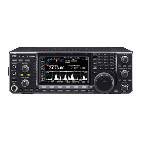
Icom IC-7600 Instruction Manual
Hf/50 mhz transceiver
Hide thumbs
Also See for IC-7600:
- Service manual (183 pages) ,
- Instruction manual (180 pages) ,
- Instruction manual (175 pages)
Table of Contents
Advertisement
Quick Links
Download this manual
See also:
Service Manual
Advertisement
Table of Contents

Subscribe to Our Youtube Channel
Related Manuals for Icom IC-7600


Summary of Contents for Icom IC-7600
- Page 1 INSTRUCTION MANUAL HF/50 MHz TRANSCEIVER i7600...
-
Page 2: Important
10.4923MHz, 24.576MHz The crossed-out wheeled-bin symbol on your product, literature, or packaging Icom, Icom Inc. and Icom logo are registered trademarks of Icom reminds you that in the European Union, all Incorporated (Japan) in Japan, the United States, the United King-... -
Page 3: Precautions
OFF and remove the power cable if it emits an the radio’s RF output power to less than the linear abnormal odor, sound or smoke. Contact your Icom amplifier’s maximum input level, otherwise, the linear dealer or distributor for advice. -
Page 4: About The Supplied Cd
ABOUT THE SUPPLIED CD Starting the CD The following instructions and installer are included on the CD. Insert the CD into the CD drive. • Double click “Menu.exe” on the CD. • Instruction manual • Depending on the PC setting, the Menu screen shown below is automatically displayed. - Page 5 FUNCTIONS AND FEATURES OF ADOBE READER ® ® The following functions and features can be used with Adobe ® Reader ® • Keyword search Click “Find (Ctrl+F)” or “Advanced • Find screen Search (Shift+Ctrl+F)” in the Edit menu to open the search screen. This is convenient when search- •...
-
Page 6: Table Of Contents
......22 ■ CW sidetone function ........42 Connecting the IC-PW1/EURO ....22 APF (Audio Peak Filter) operation ....43 Connecting a non-Icom linear amplifier ..22 Electronic keyer functions ....... 44 ■ Transverter jack information ......23 ■ Memory keyer screen ........ - Page 7 RTTY (FSK) operation ........50 Dualwatch operation ........87 ■ ■ About RTTY reverse mode ......51 Noise blanker ..........89 ■ Twin peak filter ..........51 NB set mode ..........89 Functions of the RTTY decoder display ..52 Noise reduction ..........
-
Page 8: Table Of Contents
TABLE OF CONTENTS 6 MEMORY OPERATION ......107–112 9 CLOCK AND TIMERS ......123–125 Memory channels ......... 107 Clock set mode ..........123 ■ ■ Memory channel selection ......107 Daily timer setting ......... 124 ■ ■ Using the [ ∫]/[√] keys ....... - Page 9 12 CONTROL COMMAND ......159–169 Remote jack (CI-V) information ..... 159 ■ CI-V connection ......... 159 Preparing ........... 159 Data format ..........159 Command table ......... 160 Data content description ......166 13 SPECIFICATIONS AND OPTIONS ..170–172 General ............170 ■...
-
Page 10: Panel Description
• An unmount operation should be performed before or connected external speaker is disabled. removing the USB-Memory*. (p. 150) Connects a PC keyboard for RTTY and PSK ➥ operations, etc. • Only USB keyboards* are supported. *: A USB-Memory and USB keyboard are not supplied by Icom. - Page 11 RF GAIN + SQL RTTY/PSK Decreases Push AM, FM RF GAIN + SQL Recommended level for • When setting as an RF gain/squelch control an Icom microphone Noise squelch (FM mode) Recommended level Squelch is open. MIC GAIN Maximum RF gain RF gain i AF CONTROL [AF] (inner control;...
- Page 12 PANEL DESCRIPTION Front panel (continued) ■ TIMER SPLIT LOCK TWIN-PBT SPLIT HF/50MHz TRANSCEIVER POWER DUAL WATCH TRANSMIT TUNER MONITOR GENE F-INP CHANGE PHONES MP-W MP-R PBT - CLR NOTCH APF/TPF MAIN /SUB NOTCH CW PITCH M.SCOPE VFO/MEMO ELEC-KEY RF/SQL CLEAR RIT/ TX AUTO F- 1...
- Page 13 PANEL DESCRIPTION MF3 (MULTI-FUNCTION 3 SWITCH) MF6 (MULTI-FUNCTION 6 SWITCH) P.AMP SWITCH (P.AMP) (p. 80) VOX SWITCH (VOX) (p. 92) ➥ Selects one of 2 receive RF preamps ➥ Push to turn the VOX function ON or bypasses them. or OFF during the SSB, AM and FM •...
- Page 14 PANEL DESCRIPTION Front panel (continued) ■ TIMER SPLIT LOCK TWIN-PBT SPLIT HF/50MHz TRANSCEIVER POWER DUAL WATCH TRANSMIT TUNER MONITOR GENE F-INP CHANGE PHONES MP-W MP-R PBT - CLR NOTCH APF/TPF MAIN /SUB NOTCH CW PITCH M.SCOPE VFO/MEMO ELEC-KEY RF/SQL CLEAR RIT/ TX AUTO F- 1...
- Page 15 PANEL DESCRIPTION @1 MODE SWITCHES @5 VOICE MEMORY PLAYBACK SWITCH [PLAY] Selects the desired mode. (p. 36) (p. 98) • Announces the selected mode via the speech ➥ Push to playback the selected voice memory in synthesizer. (p. 39) the RX memory screen for the preset time period. [SSB] •...
- Page 16 ON. other stacked frequencies in the band. (p. 29) (p. 96) • Icom’s triple band stacking register memorizes 3 ➥ Equalizes the sub readout frequency to the frequencies in each band. ➥ After pushing [F-INP ENT], push a key on the main readout frequency when held down for 1 second.
- Page 17 PANEL DESCRIPTION #9 PASSBAND TUNING CONTROLS [TWIN-PBT] What is the notch function? ✓ (p. 83) The notch function is a narrow filter that eliminates Adjusts the receiver’s IF filter passband width via unwanted CW or AM carrier tones while the DSP. preserving the desired voice signal.
- Page 18 PANEL DESCRIPTION ■ Front panel (continued) $7 $8 $9 %0 %1 TIMER SPLIT LOCK TWIN-PBT SPLIT HF/50MHz TRANSCEIVER POWER DUAL WATCH TRANSMIT TUNER MONITOR GENE F-INP CHANGE PHONES MP-W MP-R PBT - CLR NOTCH APF/TPF MAIN /SUB NOTCH CW PITCH M.SCOPE VFO/MEMO ELEC-KEY...
- Page 19 PANEL DESCRIPTION %3 CW PITCH CONTROL [CW PITCH] (outer control; p. 42) Shifts the received CW audio pitch and the CW side-tone pitch without changing the operating frequency. Higher pitch Lower pitch %4 MANUAL NOTCH FILTER CONTROL [NOTCH] (inner control; p. 91) Varies the notch frequency of the manual notch filter to reject an interfering signal while the manual notch function is ON.
-
Page 20: Rear Panel
Select “USB” in the ACC set mode item ‘DATA OFF transceiver. MOD,’ ‘DATA1 MOD,’ ‘DATA2 MOD’ or ‘DATA3 MOD.’ ➥ Used for transceive operation with another Icom And the modulation input level from USB jack can CI-V transceiver or receiver. - Page 21 NOTE: T/R control voltage and current must be less than 16 V DC/0.5 A (or 250 V AC, 200 mA with MOSFET switching). !4 ALC INPUT JACK [ALC] (p. 18) Connects to the ALC output jack of a non-Icom linear amplifier.
-
Page 22: Lcd Display
PANEL DESCRIPTION ■ LCD display @2 @3 q S/RF METER (pp. 38, 134) w IF FILTER INDICATOR (p. 84) Shows the signal strength while receiving. Shows Shows the selected IF filter number. the relative output power, SWR, ALC, VD, ID or e QUICK TUNING INDICATOR (p. - Page 23 PANEL DESCRIPTION o RTTY TUNING INDICATOR @2 NOTCH INDICATOR (p. 91) Shows the tuning condition in the RTTY mode. ➥ “ ” appears when the manual notch function is in use. This function is available in SSB, !0 MODE INDICATOR CW, RTTY, PSK and AM modes.
-
Page 24: Screen Menu Arrangement
PANEL DESCRIPTION ■ Screen menu arrangement The following screens can be selected from the start- Pushing [EXIT/SET] several times returns to the start- up screen. Choose the desired screen using the fol- up screen. See page 127 for set mode arrangement. lowing chart. -
Page 25: Installation And Connections
For a description and a diagram of accessory antenna, and feedline. We recommend 1.5:1 or ø equipment included with the IC-7600, see ‘Supplied better of Voltage Standing Wave Ratio (VSWR) on accessories’ on p. i of this manual. your operating bands. The transmission line should be a coaxial cable. -
Page 26: Required Connections
INSTALLATION AND CONNECTIONS ■ Required connections Front panel CW KEY TIMER SPLIT LOCK TWIN-PBT SPLIT HF/50MHz TRANSCEIVER POWER DUAL WATCH TRANSMIT TUNER MONITOR GENE F-INP CHANGE PHONES MP-W MP-R PBT-CLR NOTCH APF/TPF MAIN /SUB NOTCH CW PITCH M.SCOPE VFO/MEMO ELEC-KEY RF/SQL CLEAR RIT/ TX... -
Page 27: Advanced Connections
RX ANT IN/OUT (pp. 22, 26) Connect external (p. 171) preamp or lowpass filter. [ALC], [SEND] (p. 22) The antenna connector SP-23 Used to connect a non- must be selected as “ANT (option) Icom linear amplifier. 1/R” or “ANT 2/R.” (p. 3) -
Page 28: D Rear Panel- 2
NEVER connect or remove the USB-Memory when the read/write indicator is lit or blinks. A USB keyboard* or a USB hub* can also be con- nected to the USB connector. * USB-Memory, USB keyboard and USB hub are not sup- plied by Icom. -
Page 29: Power Supply Connections
Connect the optional PS-126 to the transceiver. CAUTION: Before connecting the DC power If you use a non-Icom power supply, be sure that the cable, check the following important items. Make output voltage of the power supply is 13.8 V DC sure: ±... -
Page 30: External Antenna Tuner Connection
D Connecting an AH-4 The optional AH-4 matches the IC-7600 to a long • See page 122 for operation. wire antenna more than 7 m/23 ft long (3.5 MHz and • See the AH-4 instruction manual for installation and above). -
Page 31: Linear Amplifier Connections
0.5 A DC with initial setting, and 250 V/ 200 mA with “MOSFET” setting (see page 133 for details). RF OUTPUT RF INPUT Use an external relay unit if your non-Icom linear amplifier requires control voltage and/or current SEND greater than specified. -
Page 32: Transverter Jack Information
D When connecting to the USB connector Connect a USB cable (user supplied) between the transceiver’s USB connector [USB] (B) on the rear panel and the PC. (p. 19) • The USB driver and the installation guide can be downloaded from our website (http://www.icom.co.jp/world/index.html). -
Page 33: Microphone Connector Information
2 to ground as this r Main readout squelch switch can damage the internal 8 V regulator. DC voltage is applied to pin 1 for microphone operation. Use caution when using a non-Icom microphone. ■ Microphones D HM-36 q UP AND DOWN SWITCHES [UP]/[DN] Change the selected readout frequency or memory channel. - Page 34 INSTALLATION AND CONNECTIONS Microphones (Continued) ■ D SM-50 TOP VIEW q PTT SWITCH Hold down to transmit, release to receive. w PTT LOCK SWITCH Push to lock the PTT switch in the transmit mode. e UP/DOWN SWITCHES [UP]/[DN] Change the selected readout frequency or memory channel.
-
Page 35: Installation And Connections
When the SEND terminal controls the inductive load [Example] (such as a relay), a counter-electromotive force can Switching diode cause the transceiver’s malfunction or damage. To To a non-Icom socket linear amplifier prevent this, we recommend adding a switching e HSEND diode, such as an “1SS133,”... -
Page 36: Basic Operation
BASIC OPERATION ■ Before first applying power Before first applying power, make sure all connections After all connections have been done, set controls required for your system are complete by referring to and switches as shown in the figure below. Chapter 2. -
Page 37: Selecting Vfo/Memory Mode
VFO mode. (p. 110) “VFO” indicator Memory channel number ■ Main/Sub band selection The IC-7600 has a main and a sub band. MAIN The main band is displayed on the left hand side, and /SUB M.SCOPE M.SCOPE... -
Page 38: Selecting An Operating Band
BASIC OPERATION ■ Selecting an operating band Band keys The triple band stacking register provides 3 memories for each band key, for storing frequency and mode information. This function is convenient when you operate 3 operating modes on one band. For example, one register is used for a CW frequency, another for a SSB frequency and the other one for a RTTY frequency. -
Page 39: Frequency Setting
BASIC OPERATION ■ Frequency setting The transceiver has several tuning methods for convenient frequency tuning. Band keys D Tuning with the main dial Push the desired band key on the keypad 1–3 times. • 3 different frequencies can be selected on each band with the band key. -
Page 40: About The 5 Mhz Band Operation (Usa Version Only)
BASIC OPERATION D About the 5 MHz band operation (USA version only) • For the USB and USB Data modes Operation on the 5 MHz frequency band is allowed on 5 discrete frequencies and must adhere to the The FCC specifies center frequencies on the 5 MHz following: frequency band. -
Page 41: Quick Tuning Step
BASIC OPERATION D Quick tuning step The operating frequency can be changed in larger steps (0.1, 1, 5, 9, 10, 12.5, 20 or 25 kHz selectable) for quick tuning. Push [TS] to turn the quick tuning function ON. • “Z” appears when the quick tuning function is ON. Rotate the main dial to change the frequency in programmed kHz steps. -
Page 42: Auto Tuning Step Function
BASIC OPERATION D Auto tuning step function When rotating the main dial rapidly, the tuning speed OTHERS automatically accelerates, as selected. Push [EXIT/SET] several times to close any multi- function screens, if necessary. [SET] (F-6) to select the set mode menu Push screen. -
Page 43: Band Edge Warning Beep
BASIC OPERATION D Band edge warning beep This function allows you to hear a beep tone when you tune in or out of an amateur band’s frequency range. A regular beep sounds when you tune into a range, and an lower tone error beep will sound when you tune out of a range. - Page 44 BASIC OPERATION Band edge warning beep (Continued) BAND To programming the band edge: Keypad [DEL] [INS] q Perform the steps q to t as shown above, then select either “ON (User)” or “ON (User) & TX Limit” setting. • [BAND] appears above the function switch (F-5). w Push [BAND] (F-5) to open the band edge screen.
-
Page 45: Operating Mode Selection
SSB (USB/LSB), SSB data (USB data/LSB data), CW, CW reverse (CW-R), RTTY, RTTY reverse (RTTY-R), PSK, PSK reverse (PSK-R), AM, AM data, FM and FM data modes are available in the IC-7600. Push the desired mode switch to select a mode of operation. -
Page 46: Squelch And Receive (Rf) Sensitivity
BASIC OPERATION ■ Squelch and receive (RF) sensitivity Adjusts the RF gain and squelch threshold level. The squelch removes noise output from the speaker (closed position) when no signal is received. • The squelch is particularly effective for AM and FM. It is also available for other modes. -
Page 47: Volume Setting
Displays the drain terminal voltage of the final amplifier MOSFETs. D Multi-function digital meter The IC-7600 can display the multi-function digital meter on the LCD display. This meter displays all transmit parameters simultaneously. q Hold down [METER] (MF2) for 1 second to turn the... -
Page 48: Meter Type Selection
BASIC OPERATION D Meter type selection DISP A total of 3 meter types are available in the IC-7600— Standard, Edgewise and Bar meters. Follow the instructions below for the meter type selection. q Push [EXIT/SET] several times to return to the normal screen, if necessary. -
Page 49: Basic Transmit Operation
ALC zone Decreases Push t Release [PTT] (microphone) to return to receive. Recommended level for an Icom microphone In addition, the transceiver can display the multi- function digital meter in the LCD, which displays all transmit meters simultaneously. MIC GAIN... -
Page 50: Drive Gain Adjustment
BASIC OPERATION D Drive gain adjustment The drive gain is active for all modes, other than SSB mode with speech compressor OFF. Before transmitting, monitor your selected operating frequency to make sure transmitting won’t cause interference to other stations on the same frequency. TRANSMIT METER q Push [EXIT/SET] several times to return to the... -
Page 51: Receive And Transmit
RECEIVE AND TRANSMIT ■ Functions for CW operation D About CW reverse mode CW-R (CW Reverse) mode uses the opposite side band to receive CW signals. Use when interfering signals are near a desired signal Push and you want to use CW-R to reduce the interference. ➥... -
Page 52: Apf (Audio Peak Filter) Operation
RECEIVE AND TRANSMIT D APF (Audio Peak Filter) operation The APF changes the audio frequency response by boosting a particular frequency to enhance a desired CW signal. q During the CW mode, push [APF/TPF] to turn the audio peak filter ON or OFF. •... -
Page 53: Electronic Keyer Functions
RECEIVE AND TRANSMIT ■ Electronic keyer functions The IC-7600 has a number of convenient functions for the built-in electronic keyer that can be accessed from the memory keyer menu. KEYER q During the CW mode, push [EXIT/SET] several times to return to the normal screen, if necessary. -
Page 54: Memory Keyer Screen
RECEIVE AND TRANSMIT D Memory keyer screen KEYER Pre-set characters can be sent using the keyer send −1 menu. Contents of the memory keyer are set using TRANSMIT the edit menu. • Transmitting q During the CW mode operation, push [KEYER] (F-3) to select the memory keyer screen. -
Page 55: Editing A Memory Keyer
• Pushing [DEL] (F-3) deletes a character and [SPACE] Contents (F-4) inserts a space. CQ TEST CQ TEST DE ICOM ICOM TEST y Repeat steps r and t to input the desired UR 5NN✱ BK characters. -
Page 56: Contest Number Set Mode
RECEIVE AND TRANSMIT D Contest number set mode • Contest number set mode screen This menu is used to set the contest (serial) number and count-up trigger, etc. KEYER 001CLR • Setting contents q During the CW mode operation, push [KEYER] (F-3) to select memory keyer screen. -
Page 57: Keyer Set Mode
RECEIVE AND TRANSMIT D Keyer set mode CW KEY This set mode is used to set the memory keyer repeat time, dash weight, paddle specifications, keyer type, etc. • Setting contents q During the CW mode operation, push [KEYER] (F-3) to select the memory keyer screen. -
Page 58: Paddle Polarity
RECEIVE AND TRANSMIT Keyer set mode (continued) Paddle Polarity Normal This item sets the paddle dot-dash polarity. • Normal and reverse polarity can be selected. Keyer Type ELEC-KEY This item selects the keyer type for the [ELEC-KEY] • Straight key, BUG-KEY and ELEC-KEY can be connector on the front panel. -
Page 59: Rtty (Fsk) Operation
RECEIVE AND TRANSMIT ■ RTTY (FSK) operation A DSP-based high-quality Baudot RTTY encoder/ decoder is built-in to the IC-7600. When connecting a PC keyboard (pp. 18, 19), you can operates RTTY without an external RTTY terminal or PC. If you would rather use your RTTY terminal, consult the equipment manual. -
Page 60: D About Rtty Reverse Mode
RECEIVE AND TRANSMIT D About RTTY reverse mode Received characters are occasionally garbled when the received signal is reversed between Mark and Space tones. This reversal can be caused by incorrect TNC connections, setting, commands, etc. To receive a reversed RTTY signals correctly, select the RTTY-R (RTTY Reverse) mode. -
Page 61: D Functions Of The Rtty Decoder Display
RECEIVE AND TRANSMIT D Functions of the RTTY decoder display DECODE WIDE q Push a band key to select the desired band. Band keys w Push [RTTY/PSK] to select RTTY. • After RTTY is selected, hold down [RTTY/PSK] for 1 second to toggle between the RTTY and RTTY-R modes. -
Page 62: Drtty Memory Transmission
RECEIVE AND TRANSMIT D RTTY memory transmission Previously entered characters can be sent using the RTTY memory. Contents of the memory are set using the edit menu. DECODE TX MEM 1–4/5–8 q During the RTTY mode operation, push [DECODE] (F-3) to select the RTTY decode screen. w Push [TX MEM] (F-3) to select the RTTY memory screen. -
Page 63: D Editing Rtty Memory
RTTY memory ↵73 GL SK↵ contents can also be edited from the keyboard. ↵CQ CQ CQ DE ICOM ICOM ICOM K↵ ↵MY TRANSCEIVER IS IC–7600 & ANTENNA IS A 3–ELEMENT TRIBAND YAGI.↵ ↵MY RTTY EQUIPMENT IS INTERNAL FSK... -
Page 64: Drtty Decode Set Mode
RECEIVE AND TRANSMIT D RTTY decode set mode This set mode is used to set the decode USOS function, time stamp setting, etc. WIDE • Setting contents q During the RTTY mode operation, push [DECODE] (F-3) to select the RTTY decode screen. w Push [<MENU1>] (F-1) to select the second RTTY decode menu, then push [SET] (F-5) to select the RTTY decode set mode. - Page 65 RECEIVE AND TRANSMIT RTTY TX USOS Explicitly inserts the FIGS character, even though it • ON : Inserts FIGS. is not required by the receiving station. • OFF : Does not insert FIGS. RTTY Auto CR+LF by TX Selects the automatic new line code (CR+LF) •...
-
Page 66: D Data Saving
RECEIVE AND TRANSMIT D Data saving The contents of the RTTY memory/received signal The USB-Memory is not supplied by Icom. can be saved into USB-Memory. SPACE q During the RTTY decode screen display, push Symbol [<MENU1>] (F-1) to select the RTTY decode second menu. -
Page 67: Psk Operation
A high-quality DSP-based PSK encoder/decoder indicator indicator Band keys is built-in to the IC-7600. When connecting a PC keyboard (pp. 18, 19), PSK operation can be performed without PSK software installed on your PC. If desired, you can also use your PSK software. -
Page 68: D About Bpsk And Qpsk Modes
RECEIVE AND TRANSMIT D About BPSK and QPSK modes The BPSK and QPSK modes are available for PSK. • The BPSK (Binary Phase Shift Keying) mode is the most commonly used mode. • The QPSK (Quadrature Phase Shift Keying) mode has error correction capability to provide better decoding than the BPSK mode in marginal condition. -
Page 69: D Functions Of The Psk Decoder Display
RECEIVE AND TRANSMIT D Functions of the PSK decoder display q Push a band key to select the desired band. DECODE AFC/NET WIDE w Push [RTTY/PSK] to select PSK. Band keys • After the PSK mode is selected, hold down [RTTY/PSK] for 1 second to toggle between the PSK and PSK-R modes. -
Page 70: Dpsk Memory Transmission
RECEIVE AND TRANSMIT D PSK memory transmission Previously entered characters can be sent using the PSK memory. Contents of the memory are set using the edit menu. DECODE TX MEM 1–4/5–8 q During the PSK mode operation, push [DECODE] (F-3) to select the PSK decode screen. w Push [TX MEM] (F-3) to select the PSK memory screen. -
Page 71: D Editing Psk Memory
↵DE Icom Icom Icom K↵ characters. ↵QSL UR 599 599 BK↵ u Push [EXIT/SET] to set the contents and exit the ↵QSL DE Icom Icom UR 599 599 BK↵ PSK memory edit screen. ↵73 GL SK↵ ↵CQ CQ CQ DE Icom Icom Icom K↵... -
Page 72: Dpsk Decode Set Mode
RECEIVE AND TRANSMIT D PSK decode set mode This set mode is used to set the PSK AFC range, time stamp setting, etc. WIDE • Setting contents q During the PSK mode operation, push [DECODE] (F-3) to select the PSK decode screen. w Push [<MENU1>] (F-1) to select the second PSK decode menu, then push [SET] (F-5) to select the PSK decode set mode. - Page 73 RECEIVE AND TRANSMIT PSK Time Stamp (Frequency) Selects the operating frequency display for time • ON : Displays the operating frequency. stamp usage. • OFF : No operating frequency display. NOTE: The frequency won’t be displayed when “OFF” is selected in “PSK Time Stamp” as shown below left.
-
Page 74: D Data Saving
RECEIVE AND TRANSMIT D Data saving The contents of the PSK memory/received signal can The USB-Memory is not supplied by Icom. be saved into USB-Memory. SPACE q During the decode screen display, push Symbol [<MENU1>] (F-1) to select the decode second menu. -
Page 75: Repeater Operation
RECEIVE AND TRANSMIT ■ Repeater operation A repeater retransmits a received signal on a different frequency. When using a repeater, the transmit frequency is shifted from the receive frequency by an offset frequency. A repeater can be accessed using split frequency operation with the transmit frequency shifted to the repeater's receive frequency. -
Page 76: Tone Squelch Operation
RECEIVE AND TRANSMIT ■ Tone squelch operation The tone squelch opens only when receiving a signal containing a matching subaudible tone. You can silently wait for calls from group members using the same tone. TONE q Set the desired frequency band and select mode. -
Page 77: Data Mode (Afsk) Operation
RECEIVE AND TRANSMIT ■ Data mode (AFSK) operation When operating RTTY, SSTV, AMTOR or PACKET with your TNC and/or PC software in the AFSK mode, consult the manual that comes with the TNC and/or the software. Band keys q Connect a PC and TNC to the transceiver. (p. 23) w Push a band key to select the desired band. -
Page 78: Spectrum Scope Screen
The IC-7600 has two spectrum scope modes. One is the center mode, and another one is the fixed mode. You can also turn the waterfall display ON or OFF for your convenience. -
Page 79: D Using The Spectrum Scope
RECEIVE AND TRANSMIT D Using the Spectrum scope q Push [EXIT/SET] several times to close any multi- HOLD CENT/FIX WIDE/SET function screens, if necessary. Push [SCOPE](F-1). • The Spectrum scope screen is displayed. Function Action When the center mode is selected, selects the scope span. -
Page 80: D Center Mode
RECEIVE AND TRANSMIT D Center mode Displays signals around the operating frequency within the selected span. The operating frequency is always displayed in the center of the screen. q Push [EXIT/SET] several times to close any multi- function screens, if necessary. Push [SCOPE](F-1) to select the scope screen. -
Page 81: D Fixed Mode
RECEIVE AND TRANSMIT D Fixed mode Displays signals within a specified frequency range. The selected frequency band activity can be observed at a glance when using this mode. q Push [EXIT/SET] several times to close any multi- function screens, if necessary. Push [SCOPE](F-1) to select the scope screen. -
Page 82: D Mini Scope Screen
RECEIVE AND TRANSMIT D Mini scope screen The mini scope screen can be simultaneously displayed with other multi-function displays, such as a set mode menu, RTTY/PSK decode screen, or memory list screen. Hold down [M.SCOPE] for 1 second to turn the ➥... -
Page 83: D Scope Set Mode
RECEIVE AND TRANSMIT D Scope set mode This set mode is used to set the waveform color, WIDE/SET sweeping speed, scope range for fixed mode, etc. q During spectrum scope display ON, hold down [WIDE/SET] (F-6) for 1 second to select the scope set mode screen. - Page 84 RECEIVE AND TRANSMIT Scope set mode (continued) Waveform Color (Current) Set the waveform color for the currently received • The color is set in RGB format. • Push [Ω ≈] (F-3) to select R (Red), G (Green) and signals. B (Blue), and rotate the main dial to adjust the ratio from 0 to 255.
- Page 85 RECEIVE AND TRANSMIT Sweep Speed (± 25k) FAST Select the sweep speed for the ±25 kHz span selection from SLOW, MID and FAST. Sweep Speed (± 50k) FAST Select the sweep speed for the ±50 kHz span selection from SLOW, MID and FAST. Sweep Speed (±...
- Page 86 RECEIVE AND TRANSMIT Scope set mode (continued) Fixed Edges ( 8.00 − 11.00) 10.100 − 10.150 MHz Set the scope edge frequencies for fixed mode • Set the frequencies within 8.000 to 11.000 MHz scope when the 8 to 11 MHz band is selected. range in 1 kHz steps.
- Page 87 RECEIVE AND TRANSMIT Fixed Edges (30.00 − 45.00) 30.000 − 30.500 MHz Set the scope edge frequencies for fixed mode • Set the frequencies within 30.000 to 45.000 MHz scope when the 30 to 45 MHz band is selected. range in 1 kHz steps. As edge frequencies are set, the other edge frequency will be automatically set for a display band width of 5 kHz to a maximum of 500 kHz.
-
Page 88: Dusb Mouse Operation
RECEIVE AND TRANSMIT D USB mouse operation If you connect a USB mouse to the transceiver, a mouse pointer appears on the spectrum scope screen. Now, you can change the frequency by using the mouse. Clicking while holding down [XFC] changes the transmit frequency. -
Page 89: Preamplifier
RECEIVE AND TRANSMIT ■ Preamplifier The preamp amplifies received signals in the receiver front end, to improve the S/N ratio and sensitivity. Set this to preamp 1 or preamp 2 when receiving weak signals. P.AMP ➥ Push [P.AMP] (MF3) several times to set the preamp OFF, preamp 1 ON or preamp 2 ON. -
Page 90: Rit Function
RECEIVE AND TRANSMIT ■ RIT function The RIT (Receive Increment Tuning) function compensates for off-frequency operation of the received station. The function shifts the receive frequency up to ±9.999 kHz in 1 Hz steps (10 Hz steps when cancelling CLEAR the 1 Hz step readout) without moving the transmit frequency. -
Page 91: Agc Function
RECEIVE AND TRANSMIT ■ AGC function The AGC (auto gain control) controls receiver gain to produce a constant audio output level even when the received signal strength varies greatly. The transceiver has 3 preset AGC characteristics (time constant: fast, mid, slow) for non-FM modes. The FM mode AGC time constant is fixed as ‘FAST’... -
Page 92: Twin Pbt Operation
In general, the PBT (Passband Tuning) electronically narrows the IF passband width by shifting the IF frequency to slightly outside of the IF filter passband, to reject interference. The IC-7600 uses DSP for the PBT function. You can watch the nearby intended signal using the FILTER spectrum scope. -
Page 93: If Filter Selection
RECEIVE AND TRANSMIT ■ IF filter selection The transceiver has 3 passband width IF filters for each mode. For the SSB, CW and PSK modes, the passband width can be set between 50 and 3600 Hz in 50 or 100 Hz steps. -
Page 94: D Roofing Filter Selection
RECEIVE AND TRANSMIT D Roofing filter selection The IC-7600 has 3, 6 and 15 kHz roofing filters at the 1st IF frequency. The roofing filter provides ROOFING interference reduction from nearby strong signals. q Hold down [FILTER] for 1 second to select the filter set screen. -
Page 95: D Filter Shape Set Mode
RECEIVE AND TRANSMIT D Filter shape set mode The type of DSP filter shape for SSB, SSB data and CW can be selected independently from soft and sharp. • Filter shape set mode Hold down [FILTER] for 1 second to select the filter set screen. -
Page 96: Dualwatch Operation
RECEIVE AND TRANSMIT ■ Dualwatch operation Dualwatch monitors 2 frequencies with the same DUAL SPLIT CHANGE WATCH mode simultaneously. During dualwatch, both frequencies should be on the same band, because the bandpass filter in the RF circuit is selected for the main readout frequency. q Set a desired frequency into the main band. - Page 97 RECEIVE AND TRANSMIT • Scanning during dualwatch Scanning operates only for the main readout. DUAL SPLIT WATCH To operate the scan during dualwatch, scan on the main readout and use the sub readout for your QSO using both dualwatch and split frequency operation. q Program the desired programmed scan edges in the same amateur band.
-
Page 98: Noise Blanker
RECEIVE AND TRANSMIT ■ Noise blanker <MODE> SSB/CW/RTTY/PSK/AM The noise blanker eliminates pulse-type noise such as the noise from car ignitions. The noise blanker is not available for FM mode. ➥ Push [NB] to turn the noise blanker function ON or OFF. -
Page 99: Noise Reduction
RECEIVE AND TRANSMIT ■ Noise reduction The noise reduction function reduces random noise components and enhances desired signals which are buried in noise. The DSP performs the random noise reduction function. q Push [NR] to turn the noise reduction ON. •... -
Page 100: Notch Function
RECEIVE AND TRANSMIT ■ Notch function This transceiver has auto and manual notch functions. The auto notch function uses DSP to automatically attenuate beat tones, tuning signals, etc., even if they are moving. The manual notch can be set to attenuate a frequency via the [NOTCH] control. -
Page 101: Vox Function
RECEIVE AND TRANSMIT ■ VOX function <MODE> SSB/AM/FM The VOX (Voice-Operated Transmission) function switches between transmit and receive with your voice. This function provides “hands-free” operation. D Using the VOX function q Select a phone mode (SSB, AM, FM). w Push [VOX] (MF6) to turn the VOX function ON or OFF. -
Page 102: Break-In Function
■ Break-in function <MODE> CW The break-in function is used in the CW mode to automatically toggle the transceiver between transmit and receive when keying. The IC-7600 is capable of full break-in or semi break-in. D Semi break-in operation BK-IN... -
Page 103: Speech Compressor
RECEIVE AND TRANSMIT ■ Speech compressor <MODE> SSB The speech compressor increases average RF output power, improving signal strength and readability. COMP q Push [SSB] to select the USB or LSB mode. w Hold down [COMP] (MF7) for 1 second to select the COMP TBW set screen. -
Page 104: Tx Function
RECEIVE AND TRANSMIT ■ ∂TX function The ∂TX function shifts the transmit frequency up to ±9.999 kHz in 1 Hz steps (10 Hz steps when cancelling the 1 Hz step readout) without moving the receive frequency. ∂TX CLEAR q Push [ ] to turn ∂TX ∂TX function ON. -
Page 105: Split Frequency Operation
RECEIVE AND TRANSMIT ■ Split frequency operation Split frequency operation allows you to transmit and receive in the same mode on two different frequencies. Split frequency operation is performed MAIN using 2 frequencies on the main and sub readouts. /SUB [SPLIT] indicator M.SCOPE M.SCOPE... -
Page 106: Quick Split Function
RECEIVE AND TRANSMIT ■ Quick split function When you find a DX station, an important consideration is how to set the split frequency. When you hold down the [SPLIT] switch for 1 second, the split frequency operation is turned ON, and the sub readout frequency and operating mode is equalized to the main readout, then enters standby for transmit frequency input. -
Page 107: Voice Recorder Functions
VOICE RECORDER FUNCTIONS ■ About digital voice recorder The IC-7600 has digital voice memories, up to 4 messages for transmit, and up to 20 messages for receive. A maximum message length of 30 seconds can be recorded into receive memory (total message length... -
Page 108: Recording A Received Audio
VOICE RECORDER FUNCTIONS ■ Recording a received audio Up to 20 receive voice memories can be recorded in the IC-7600. A total of 209 seconds of audio can be recorded in receive messages. However, the maximum recordable length of a single message is 30 seconds. -
Page 109: Playing The Recorded Audio
VOICE RECORDER FUNCTIONS ■ Playing the recorded audio PLAY D Basic playing q Push [EXIT/SET] several times to close any multi- function screens, if necessary. w Push [VOICE] (F-2) to call up the voice recorder screen. • Previously selected screen, TX or RX memory, is displayed. -
Page 110: Protect The Recorded Contents
VOICE RECORDER FUNCTIONS ■ Protect the recorded contents The protect function is available to protect the recorded contents from accidental erasure, such as over-writing, etc. q Call up the voice recorder screen, RX memory. w Push [Y] (F-1) or [Z] (F-2) to select the desired voice message. -
Page 111: Recording A Message For Transmit
To transmit a message using the voice recorder, record the desired message in advance as described below. The IC-7600 has digital voice memories for transmission, up to 4 messages and a total message length of up to 99 seconds can be recorded. -
Page 112: Programming A Memory Name
VOICE RECORDER FUNCTIONS ■ Programming a memory name Memory messages can be tagged with alphanumeric names of up to 30 characters each. Capital letters, small letters, numerals, some symbols (! # $ % & ¥ ? " ’ ` ^ + – ✱ / . , : ; = < > ( ) [ ] { } ¦ _ – @) NAME T1..T4 and spaces can be used. -
Page 113: Sending A Recorded Message
VOICE RECORDER FUNCTIONS ■ Sending a recorded message q Push [EXIT/SET] several times to close any multi- function screens, if necessary. w Select a phone mode by pushing [SSB] or [AM/FM]. e Push [VOICE] (F-2) to call up the voice recorder screen. -
Page 114: Voice Set Mode
VOICE RECORDER FUNCTIONS ■ Voice set mode Sets the automatic monitor function, short play and normal recording times for voice recorder. q Push [EXIT/SET] several times to close any multi- function screens, if necessary. w Push [VOICE] (F-2) to call up the voice recorder screen. -
Page 115: Saving A Voice Message Into The Usb-Memory
■ Saving a voice message into the USB-Memory D Saving the received audio memory The recorded RX memory contents can be saved into The USB-Memory is not supplied by Icom. the USB-Memory. SPACE q During voice recorder RX memory screen display, Symbol push [SAVE] (F-5) to select voice file save screen. -
Page 116: Memory Operation
MEMORY OPERATION ■ Memory channels The transceiver has 101 memory channels. The All 101 memory channels are tunable, which means Memory mode is very useful to quickly change to the programmed frequency can be tuned temporarily often-used frequencies. with the main dial, etc. in memory mode. MEMORY MEMORY TRANSFER... -
Page 117: Memory List Screen
MEMORY OPERATION ■ Memory list screen The memory list screen simultaneously shows 7 memory channels and their programmed contents. 13 memory channels can be displayed in the wide memory list screen. You can select a desired memory channel from the memory list screen. -
Page 118: Memory Channel Programming
MEMORY OPERATION ■ Memory channel programming Memory channel can be programmed in either the VFO mode or the memory mode. D Programming in the VFO mode q Set the desired frequency, operating mode and filter width in the VFO mode. w Push [∫]/[√] several times to select the desired memory channel. -
Page 119: Frequency Transfers
MEMORY OPERATION ■ Frequency transfers The frequency and operating mode in a memory channel can be transferred to the VFO in either VFO mode or memory mode. D Transferring in the VFO mode This is useful for transferring programmed contents to a VFO. -
Page 120: Memory Names
MEMORY OPERATION ■ Memory names All memory channels (including scan edges) can be tagged with alphanumeric names of up to 10 characters each. Capital letters, small letters, numerals, some symbols (! # $ % & ¥ ? " ’ ` ^ + – ✱ / . , : ; = < > ( ) [ ] { } ¦ _ – @) and space can be used. -
Page 121: Memo Pads
MEMORY OPERATION ■ Memo pads The transceiver has a memo pad function to store frequency and operating mode for easy writing and recalling. The memo pads are separate from the memory channels. The default number of memo pads is 5. If desired, however, this can be increased to 10 in the set mode. -
Page 122: Scans
SCANS ■ Scan types • The scan function can be used on the main readout only. • You can perform a scan while operating on a frequency using the dualwatch or split functions. PROGRAMMED SCAN ∂F SCAN Repeatedly scans between two scan edge frequencies Repeatedly scans within ∂F span area. -
Page 123: Scan Set Mode
SCANS ■ Scan set mode SCAN The scan speed and the scan resume condition can be set using the scan set mode. q Push [SCAN] (F-5) to select scan screen. w Push [SET] (F-6) to select the scan set mode. e Push [Y] (F-1) or [Z] (F-2) to select the desired item. -
Page 124: Programmed Scan Operation
SCANS ■ Programmed scan operation q Push [EXIT/SET] several times to close any multi- function screens, if necessary. w Select the VFO mode. e Select the desired operating mode. • The operating mode can also be changed while scanning. r Push [SCAN] (F-5) to select the scan screen. t Set [RF/SQL] open or closed. -
Page 125: Fine Programmed Scan/Fine ∂F Scan
SCANS ■ Fine programmed scan/Fine ∂F scan In fine scan (programmed or ∂F), the scan speed decreases when the squelch opens, but the transceiver keeps scanning. The scanning tuning step shifts from 50 Hz to 10 Hz when the squelch opens. ∂F FINE q Push [EXIT/SET] several times to close any multi-... -
Page 126: Memory Scan Operation
SCANS ■ Memory scan operation q Push [EXIT/SET] several times to close any multi- function screens, if necessary. w Select memory mode. e Push [SCAN] (F-5) to select the scan screen. r Set [RF/SQL] open or closed. • See page 113 for squelch condition. •... -
Page 127: Setting Select Memory Channels
SCANS ■ Setting select memory channels D Setting in scan screen SELECT MEMORY q Push [EXIT/SET] several times to close any multi- function screens, if necessary. w Select memory mode. e Push [SCAN] (F-5) to select the scan screen. r Select the desired memory channel to set as a select memory channel. -
Page 128: Tone Scan
SCANS ■ Tone scan The transceiver can detect subaudible tones in a received signal. By monitoring a signal that is being transmitted on a repeater input frequency, you can determine the tone frequency required to access the repeater. q Set the desired frequency or memory channel to T-SCAN be checked for a tone frequency. -
Page 129: Antenna Tuner Operation
ANTENNA TUNER OPERATION ■ Automatic antenna selection The transceiver covers 0.03–60 MHz over 10 bands. Each band key has a band memory which can memorize a selected antenna (ANT1, ANT2, ANT1/ RX antenna and ANT2/RX antenna). When you change the operating frequency beyond a band, the previously used antenna is automatically selected. -
Page 130: Antenna Tuner Operation
ANTENNA TUNER OPERATION ■ Antenna tuner operation The internal automatic antenna tuner automatically NOTES: matches the transceiver to the connected antenna. • NEVER transmit without an antenna properly After the tuner matches an antenna, the variable connected to antenna port in use. capacitor settings are memorized as a preset point •... -
Page 131: Optional External Tuner Operation
ANTENNA TUNER OPERATION • Automatic tuner start (HF bands only) • PTT tuner start If you want to deactivate the tuner under conditions Tuning of the internal*/external antenna tuner starts of VSWR 1.5:1 or less, use the auto tuner start when [PTT] is pushed on a new frequency (more function and turn the tuner OFF. -
Page 132: Clock And Timers
CLOCK AND TIMERS ■ Clock set mode The IC-7600 has a built-in calendar and 24-hour clock (accuracy ±75 seconds per month) with daily power ON/OFF timer functions. Before operating these timer functions, set the current date and time. q Push [EXIT/SET] several times to close multi- function screen, if necessary. -
Page 133: Daily Timer Setting
CLOCK AND TIMERS ■ Daily timer setting TIMER1 TIMER2 TIMER3 TIMER4 TIMER5 The transceiver turns power ON and/or OFF automatically on the specified day and time, with the specified frequency settings. q Push [EXIT/SET] several times to close multi- function screen, if necessary. w Push [SET] (F-6) to select the set mode menu screen. -
Page 134: Setting Sleep Timer
CLOCK AND TIMERS ■ Setting sleep timer SLEEP The sleep timer turns the transceiver power OFF TIMER POWER automatically after passing the set period. The timer can be set to 5–120 minutes in 5 minute steps. The sleep timer function counts the ‘minute’ units, and does not count the ‘second’... -
Page 135: Set Mode
■ Set mode description The set mode is used for programming infrequently changed values or conditions of functions. The IC-7600 has a level set mode, display set mode, time set mode, accessory set mode, others set mode and USB-Memory set menu. -
Page 136: D Screen Arrangement
SET MODE D Screen arrangement • Display set mode (p. 134) • Set mode menu screen (p. 126) • Time set mode (p. 123) • Level set mode (p. 128) • Others set mode (p. 136) • ACC set mode (p. 132) •... -
Page 137: Level Set Mode
SET MODE ■ Level set mode RX HPF/LPF – – – – – – – Sets the high-pass filter (100 to 2000 Hz) and low- pass filter (500 to 2400 Hz) of the receive audio in 100 Hz steps in the SSB mode. (default: OFF) NOTE: When this setting is active, below 2 items will be reset to default value, ‘0.’... - Page 138 SET MODE Level set mode (Continued) ■ RX HPF/LPF – – – – – – – Sets the high-pass filter (100 to 2000 Hz) and low- pass filter (500 to 2400 Hz) of the receive audio in 100 Hz steps in the CW mode. (default: OFF) RTTY RX HPF/LPF –...
-
Page 139: Speech Level
SET MODE SSB TBW (WIDE) – 2900 Sets the transmission passband width to a wide • Lower freq. : 100 (default), 200, 300 and 500 Hz setting by changing the lower and higher cut-off • Higher freq. : 2500, 2700, 2800 and frequencies. -
Page 140: Beep Level
SET MODE Level set mode (Continued) ■ APF AF Level 0 dB Sets the audio level for the audio peak filter in the CW mode from 0 to +6 dB in 1 dB steps. 50 % Beep Level Sets the beep output level from 0% to 100% in 1% steps. -
Page 141: Acc Set Mode
SET MODE ■ ACC set mode USB Audio SQL OFF (OPEN) Sets the squelch condition of the USB audio which • OFF (OPEN): The received audio is always output is output from the [USB] (B) connector on the rear regardless of the squelch condition. panel. -
Page 142: Ref Adjust
Reed and MOS-FET. (16 V DC/0.5 A max.: default) Select the suitable relay type when connecting a • MOS-FET : Use semiconductor type relay. non-Icom linear amplifier. (250 V/200 mA max.) External Meter Output Auto Selects the desired item for an external meter •... -
Page 143: Display Set Mode
SET MODE ■ Display set mode Bright (LCD) 50 % Adjusts the LCD unit brightness from 0% (dark) to NOTE: When you set the LCD brightness to 0%, 100% (bright) range in 1% steps. (default: 50%) nothing may appear on the screen. Adjust the LCD brightness until some indicators appear on the screen, then set it to your desired level. -
Page 144: Screen Saver Function
SET MODE Display set mode (Continued) ■ APF−Width Popup (APF OFF➔ON) Selects the pop-up display for the APF filter width from ON or OFF. (default: ON) MN−Q Popup (MN OFF➔ON) Enables the pop-up display capability when the notch filter width is changed from ON to OFF. (default: ON) Screen Saver Function 60min... -
Page 145: Others Set Mode
SET MODE ■ Others set mode Calibration Marker This item is used for a simple frequency check of the • OFF : Calibration marker OFF (default) transceiver. • ON : Calibration marker ON See page 155 for calibration procedure. NOTE: Turn the calibration marker OFF after checking the frequency of the transceiver. -
Page 146: Quick Split
SET MODE Others set mode (Continued) ■ TX Delay (50M) If the transceiver transmits power before an external Set the TX delay time on the 50 MHz band to 10, device, such as a linear amplifier, is ready to 15, 20, 25, or 30 milliseconds, or select “OFF” for no operate, the transmitted power will be reflected back delay time, depending on the needs of your external and can damage the transceiver. - Page 147 SET MODE Tuner (Auto Start) The internal antenna tuner has an automatic start • OFF : The tuner remains OFF even when the capability, which starts tuning if the SWR is high. SWR is high. (default: OFF) • ON : Automatic tune starts even when the tuner is turned OFF during HF bands operation.
- Page 148 Selects the speech speed from HIGH (faster) and LOW (slower). (default: HIGH) SPEECH S-Level The IC-7600 speech processor can announce • OFF : Signal level is not announced. (Operating frequency, mode and signal level. Signal level frequency and mode are announced.) announcement can be deactivated if desired.
-
Page 149: Memopad Numbers
SET MODE Memopad Numbers Sets the number of memo pad channels available. 5 or 10 memo pads can be selected. (default: 5) MAIN DIAL Auto TS HIGH Sets the auto tuning step function for the main dial. • HIGH : Approximately 5 times faster when the When rapidly rotating the main dial, the tuning step tuning step is set to 1 kHz or smaller steps, automatically changes several times as selected. - Page 150 SET MODE Others set mode (Continued) ■ APF Type SOFT Select audio filter shape for APF between SOFT and • SHARP : The Sharp filter shape rejects interfering SHARP. (default: SOFT) signals more aggressively. • SOFT : The Soft filter shape makes distinguishing noise and signals easier.
- Page 151 CI–V Address To distinguish equipment, each CI-V transceiver has its own Icom standard address in hexadecimal code. The IC-7600’s address is 7Ah. When 2 or more IC-7600’s are connected to an optional CT-17 , rotate the v level converter main dial to select a different address for each IC- 7600.
- Page 152 SET MODE Others set mode (Continued) ■ CI-V Output (for ANT) Enables to output the antenna controller status • OFF : Turns OFF the function. (frequency and so on) from [REMOTE]. • ON : Outputs the status. USB Serial Function CI-V Selects the [USB] connector output data format •...
-
Page 153: Usb-Memory Set Menu
SET MODE ■ USB-Memory set menu D USB-Memory set screen arrangement • USB-Memory set menu The USB-Memory is not supplied by Icom. • Setting load screen (p. 145) • Firmware update (p. 175) Hold down for 1 second • Load option set mode (p. 146) •... -
Page 154: File Loading
SET MODE ■ File loading By loading the saved setting file from the USB- Memory, you can easily set up another IC-7600 or apply the several operators settings to one IC-7600. LOAD/OPT q During the set mode menu screen display, push [USB] (F-6) to select the USB set menu screen. -
Page 155: D Load Option Set Mode
SET MODE D Load option set mode LOAD Contents Select Selects file load condition from All and Select. • All : Loads and sets the all following contents. (default: Select) • Select : Loads and sets the selected contents only. ANT Memory Selects the antenna memory setting loading •... -
Page 156: File Saving
SET MODE ■ File saving SPACE Symbol Memory channel contents, set mode settings, etc. can be saved into the USB-Memory for backup. q During the set mode menu screen display, push [USB] (F-6) to select the USB Memory set menu screen. w Push [SAVE] (F-2) to select setting save screen. -
Page 157: D Save Option Set Mode
• Old Ver : Saves the file in the firmware version To save settings and memory contents for backup format shown in brackets. or copying to another IC-7600, you must save the data in the firmware version format that matches the NOTE: target IC-7600. -
Page 158: Changing A File Name
SET MODE ■ Changing a file name The file name, saved in the USB-Memory, can be re- named from the transceiver as desired. Keypad Symbol q During the setting save screen display, push [DIR/FILE] (F-1) to select the tree view screen. •... -
Page 159: Deleting A File
SET MODE ■ Deleting a file RECOMMENDATION: Deleting the setting file is irreversible. Confirm the contents before deleting a setting file. q During the setting save screen display, push [DIR/FILE] (F-1) to select the tree view screen. • Push [Y] (F-2) or [Z] (F-3) to select the desired folder. •... -
Page 160: Set Mode
SET MODE ■ Formatting the USB-Memory Saved data in the USB-Memory can be erased. IMPORTANT! Formatting erases all saved data on the USB-Memory. Making a backup file on your PC FAT / is recommended. q During the USB Memory set menu screen display, hold down [FORMAT] (F-4) for 1 second. -
Page 161: Maintenance
If you are unable to locate the cause of a problem problems which are not equipment malfunctions. or solve it through the use of this chart, contact your nearest Icom Dealer or Service Center. D Transceiver power PROBLEM POSSIBLE CAUSE SOLUTION REF. -
Page 162: D Scanning
157 The screen saver displays • The screen saver function is activated. • Operate the transceiver. — the IC-7600 with a “bound,” • Set the screen saver function in the set mode p. 125 “rotating” or “twisting” to “OFF.”... -
Page 163: Swr Reading
SWR is lower than 3 : 1. ■ Screen type and font selections 2 types of screen images and 3 types of frequency readout display fonts are available in the IC-7600. q Push [EXIT/SET] several times to close multi- function screen, if necessary. -
Page 164: Frequency Calibration (Approximate)
However, a rough check may be performed by receiving radio station WWV, WWVH, or other standard frequency signals. CAUTION: The IC-7600 has been thoroughly adjusted and tested at the factory before being OTHERS shipped. You should not have to re-calibrate it. -
Page 165: Opening The Transceiver's Case
■ Clock backup battery replacement The IC-7600 has a lithium backup battery (CR2032) inside for clock and timer functions. The usual life of the backup battery is approximately 2 years. -
Page 166: Fuse Replacement
MAINTENANCE ■ Fuse replacement If a fuse blows, or the transceiver stops functioning, The IC-7600 has two fuse types installed for find the source of the problem, and repair it. transceiver protection. Then replace the damaged fuse with a new, •... -
Page 167: About Protection Displays
The power amplifier temperature can be monitored in the multi-function meter, TEMP gauge. ■ Screen saver function PREVIEW The IC-7600 has a screen saver function to protect the LCD from the “burn-in” effect. q Push [EXIT/SET] several times to close any multi- function screens. -
Page 168: Control Command
Connects to a PC with an RS-232C port. IC-7600 Preparing When the transceiver is connected to a PC with the The Icom Communications Interface-V (CI-V) is used USB cable (user supplied), the optional CT-17 is for remote control. not required. -
Page 169: D Command Table
CONTROL COMMAND D Command table Cmd. Data Description Cmd. Data Description cmd. cmd. see p. 166 Send frequency data for transceive 0000 to Send/read [AF] level see p. 166 Operating mode selection for transceive 0255 (0000=max. CCW, 0255=max. CW) see p. 168 Read band edge frequencies 0000 to Send/read [RF] level see p. - Page 170 CONTROL COMMAND Command table (continued) Cmd. Data Description Cmd. Data Description cmd. cmd. Preamp OFF 05 0005 00 to 10 Send/read AM RX tone (Bass) level Preamp 1 ON (00=–5, 10=+5) Preamp 2 ON 0006 00 to 10 Send/read AM RX Tone (Treble) level AGC FAST selection (00=–5, 10=+5) AGC MID selection...
- Page 171 CONTROL COMMAND Cmd. Data Description Cmd. Data Description cmd. cmd. 05 0033 [MIC] selection for MOD input connector 05 0060 Band edge beep OFF Band edge beep ON (Beep sounds with a during DATA3 [ACC] selection for MOD input connector default amateur band) during DATA3 Band edge beep with user setting ON...
- Page 172 CONTROL COMMAND Command table (continued) Cmd. Data Description Cmd. Data Description cmd. cmd. 05 0089 LSB selection for CW normal side set 05 0109 SLOW selection for scope sweep speed in USB selection for CW normal side set ±5 kHz span 0090 SHARP selection for APF type MID selection for scope sweep speed in...
- Page 173 CONTROL COMMAND Cmd. Data Description Cmd. Data Description cmd. cmd. 05 0131 M1 selection for count up trigger channel 05 0156 PSK time stamp OFF M2 selection for count up trigger channel PSK time stamp ON M3 selection for count up trigger channel 0157 Local time selection for PSK time stamp M4 selection for count up trigger channel...
- Page 174 CONTROL COMMAND Command table (continued) Cmd. Data Description cmd. Send/read transceiver’s status (RX) When “CI-V Output (for ANT)” (Command: 1C 04) is set to “ON,” automatically outputs when changed. Send/read transceiver’s status (TX) When “CI-V Output (for ANT)” (Command: 1C 04) is set to “ON,” automatically outputs when changed.
-
Page 175: D Data Content Description
CONTROL COMMAND D Data content description • Band stacking register Command: 1A 01 • Operating frequency Command: 00, 03, 05, 1C 03 q Frequency band code Code Freq. band Frequency range (unit: MHz) 1.800000– 1.999999 3.400000– 4.099999 6.900000– 7.499999 9.900000–10.499999 13.900000–14.499999 17.900000–18.499999 20.900000–21.499999... - Page 176 CONTROL COMMAND Data content description (continued) • Offset frequency setting • Color setting Command: 1A 05 0065, 0066, 0072 Command: 1A 05 0106, 0107, 0140, 0149, 0150, 0151, 0152, 0154, 0159, 0160, 0161, 0162, 0180 X X X X X X X X X R (Red) G (Green)
- Page 177 CONTROL COMMAND • Repeater tone/tone squelch frequency setting • Main or Sub band’s frequency settings Command: 1B 00, 1B 01 Command : 25 X X X X X X X X X X 0 0 00: MAIN Operating frequency data 01: SUB (See p.
-
Page 178: Control Command
CONTROL COMMAND Data content description (continued) • Memory content setting Command: 1A 00 !2 − !4 !5 − !7 !8 − @7 q, w r−i o, !0 X X X ... X X X X X X X X X X X X X X X X X X X X X X q, w Memory channel number o, !0 Operating mode setting... -
Page 179: Specifications And Options
SPECIFICATIONS AND OPTIONS ■ General ■ Receiver • Frequency coverage : (unit: MHz) • Receive system : Double superheterodyne Receive system 0.030–60.000* • Intermediate frequencies Transmit : 64.455 MHz 1.800–1.999* 3.500–3.999* : 36 kHz 5.33050* , 5.34650* , 5.36650* • Sensitivity (typical) 5.37150* , 5.40350* SSB, CW, RTTY... -
Page 180: Options
SPECIFICATIONS AND OPTIONS ■ Options IC-PW1/EURO HF/50 MHz ALL BAND 1 kW LINEAR AMPLIFIER AH-4 hf automatic antenna tuner Specially designed to tune a long wire antenna for HF/50 MHz bands Full-duty 1 kW linear amplifier including an automatic antenna tuner. Has particularly in portable or mobile automatic tuning and band selection capability. - Page 181 Icom optional equipment is designed for optimal performance when used with an Icom transceiver. Icom is not responsible for the destruction or damage to an Icom transceiver in the event the Icom transceiver is used with equipment that is not manufactured or approved by...
-
Page 182: Updating The Firmware
UPDATING THE FIRMWARE General ■ The IC-7600’s firmware can be updated if desired. By updating the firmware, new function(s) can be added and the improvement of performance parameters can be obtained. Refer to ■ Preparation (p. 174) and ■ Firmware The downloaded firmware data update (p. -
Page 183: Preparation
Access the following URL. http://www.icom.co.jp/world/index.html w Click the [Support] button. e Click the “Firmware Updates/Software Downloads” link. r Click the desired firmware file link in the IC-7600 group. t Read “Regarding this Download Service” carefully, and then click [Agree]. Click y Click [Save as] in the displayed File Download dialog. -
Page 184: Firmware Update
ON. (p. 135) q Copy the downloaded firmware data into the “IC- 7600” folder of the USB-Memory. • The USB-Memory must have been formatted by the IC-7600. w Insert the USB-Memory into the [USB] (A) connector on the front panel. [USB] (A) - Page 185 !5 Read the precaution carefully, and then push [OK] (F-5). • Return to the USB Memory set menu. !6 Push [POWER] to turn the IC-7600 power OFF, then ON again. !7 Depending on the update, one or two dialog boxes to the right appear in sequence.
-
Page 186: Installation Notes
INSTALLATION NOTES For amateur base station installations it is In all cases any possible risk depends on the recommended that the forward clearance in front of transmitter being activated for long periods. (actual the antenna array is calculated relative to the EIRP recommendation limits are specified as an average (Effective Isotropic Radiated Power). -
Page 187: Index
Connecting the IC-PW1/EURO ....... 22 Specifications ............ 170 Power supply connections ........20 Tuner operation..........121 Connecting a non-Icom DC power supply ..20 Tuning a narrow bandwidth antenna ....121 Connecting PS-126 ......... 20 APF (Audio Peak Filter) operation ......43 Required connections .......... -
Page 188: Frequency Calibration (Approximate)
Level set mode ............128 External antenna tuner connection ......21 Linear amplifier connections ........22 Connecting an AH-4 ..........21 Connecting a non-Icom linear amplifier ....22 Connecting an AH-740 ........21 Connecting the IC-PW1/EURO ......22 Load option set mode ..........146 FCC INFORMATION .......... - Page 189 RIT function ............. 81 Before first applying power ........27 RIT monitor function ..........81 Power supply ............20 Roofing filter selection ..........85 Non-Icom DC power supply ......... 20 RTTY PS-126 ..............20 Data saving ............57 Preamplifier ............. 80 Editing RTTY memory .........
- Page 190 INDEX Split frequency operation ......... 96 Direct shift frequency input ........96 Save option set mode ..........148 Dualwatch function ..........96 SCANS ..............113 Split lock function ........... 96, 97 Channels ............113 Quick split function ..........97 Fine ∂F scan ............. 116 Squelch and receive (RF) sensitivity .......
- Page 191 INDEX Vector tuning indicator display example ....58 VFO mode selection ..........28 VOICE RECORDER FUNCTIONS ......98 Playing the recorded audio ........ 100 Basic playing ..........100 One-touch playing ......... 100 Programming a memory name ......103 Recording Erasing the recorded contents ...... 101 Protect the recorded contents .......
- Page 192 MEMO...
- Page 193 MEMO...
- Page 194 MEMO...
- Page 195 MEMO...
- Page 196 IC-7600 #05 < Intended Country of Use > (Spain) IC-7600 #09 < Intended Country of Use > (Italy) IC-7600 #10 < Intended Country of Use > (France) A-6722H-1EX-r Printed in Japan © 2009−2015 Icom Inc. 1-1-32 Kamiminami, Hirano-ku, Osaka 547-0003, Japan...
Need help?
Do you have a question about the IC-7600 and is the answer not in the manual?
Questions and answers