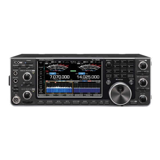
Icom IC-7610 Reference Manual
Hf/50mhz transceiver.
i/q output
Hide thumbs
Also See for IC-7610:
- Service manual (107 pages) ,
- Advanced manual (102 pages) ,
- Basic manual (80 pages)
Table of Contents
Advertisement
Advertisement
Table of Contents

Summary of Contents for Icom IC-7610
- Page 1 I/Q OUTPUT REFERENCE GUIDE HF/50MHz TRANSCEIVER i7610...
-
Page 2: Table Of Contents
Table of contents I/Q SIGNAL —————————————————————— ■ General ………………………………………………… 3 D General description ………………………………… 3 ■ Communication through the [USB 2] port ……… 4 D General description ………………………………… 4 D About the Device Description ……………………… 4 D About the endpoints ………………………………... -
Page 3: I/Q Signal
D General description You can get I/Q signals from the [USB 2] port on the IC-7610 by connecting the IC-7610 and a PC, with a USB cable. You can receive I/Q signals and control the IC-7610, through the USB cable. -
Page 4: Communication Through The [Usb 2] Port
The Device Description, that is needed to open the [USB 2] port, is shown below. “IC-7610 SuperSpeed-FIFO Bridge” D About the endpoints The IC-7610 has 3 endpoints. Each endpoint is reserved to receive I/Q data, to send control commands to the IC-7610 and to receive the acknowledgement from the IC-7610. Pipe for I/Q data... -
Page 5: About The I/Q Signals
I/Q SIGNAL ■ About the I/Q signals D General description I/Q data is output from the [USB 2] port on the IC-7610. One endpoint is reserved to receive I/Q signals. Address Endpoint Number Direction Transfer Type (Hexadecimal) (Hexadecimal) I/Q data Bulk transfer IC-7610 →... -
Page 6: Control Commands
LThere are 2 command types: Writing commands and Reading commands. Refer to the next topic for details about them. D Command format You can control the IC-7610 using the CI-V commands. Every command is composed of a byte array in hexadecimal. Every command byte must be in increments of 4 bytes. - Page 7 D Command format (Continued) Reading command format: Send a request command from the PC to request to return an IC-7610 setting value. A reading command is composed of only a command number. The IC-7610 will return the requested setting value as an acknowledgement when receiving the command.
-
Page 8: Usable Control Commands
I/Q SIGNAL ■ Usable control commands D Command description Command command Data Command Function Number Number 00/01 Send/read the dualwatch setting (00=OFF, 01=ON) 00/01 Send/read the band selection (00=Main, 01=Sub) 00/01 Send/read the split setting (00=Split OFF, 01=Split ON) 11 @9 00, 03 ~ 45 Send/read the Attenuator ( 00=ATT OFF, 03=Minimum ~ 45=Maximum (3 dB step)) 12 @9... -
Page 9: Control Commands Relative To The I/Q Port Settings
•Setting Command (PC to IC-7610) Command (PC to IC-7610) Band Band Frequency (The format is s 00:MAIN 00:MAIN 01:SUB 01:SUB Acknowledgement of a valid command (IC-7610 to PC) Band Frequency X X 00:MAIN 01:SUB •Setting Command (PC to IC-7610) Band Frequency (The format is same as above.) -
Page 10: D Operating Mode
Mode Band IF filter bandwid X X X X X X X X 00:MAIN 01:SUB Acknowledgement of a valid command (IC-7610 to PC) DATA mode Mode Band IF filter bandwidth X X X X X X X X 01:FIL 1... -
Page 11: D Setting After Directly Specifying The Main/Sub Band
F E F E 9 8 E 0 2 9 0 0 1 4 0 2 F D F F F F F F Postamble Sub command MAIN/SUB MAIN/SUB Command Acknowledgement of a valid com Acknowledgement of a valid command (IC-7610 to PC) IC-7610 address Data (RF gain) address address Preamble... - Page 12 F E F E 9 8 E 0 2 9 0 1 1 4 0 2 0 1 2 8 F D F F Postamble Sub command MAIN/SUB Command Acknowledgement of a valid command (IC-7610 to PC) IC-7610 address address Preamble...
- Page 13 A7380-10EX 1-1-32 Kamiminami, Hirano-ku, Osaka 547-0003, Japan © 2018 Icom Inc.


Need help?
Do you have a question about the IC-7610 and is the answer not in the manual?
Questions and answers