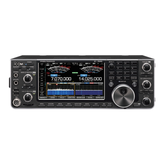
Icom iC-7610 Reference Manual
Hf/50mhz transceiver ci-v reference guide
Hide thumbs
Also See for iC-7610:
- Service manual (107 pages) ,
- Advanced manual (102 pages) ,
- Basic manual (80 pages)
Advertisement
Quick Links
Advertisement

Subscribe to Our Youtube Channel
Related Manuals for Icom iC-7610


Summary of Contents for Icom iC-7610
- Page 1 CI-V REFERENCE GUIDE HF/50MHz TRANSCEIVER i7610...
-
Page 2: Table Of Contents
Table of contents Remote control ———————————————————— 2 ■ Remote control (CI-V) information ……………… 2 D CI-V connection …………………………………… 2 D Preparing …………………………………………… 2 D About the data format …………………………… 2 D Command table …………………………………… 3 D Command formats ……………………………… 10... -
Page 3: Remote Control
The transceiver's operating frequency, mode, VFO and memory selection, can be remotely controlled using a • Use a USB cable (A-B type, user supplied) to connect the IC-7610 and the PC (controller). The required USB driver and driver installation guide can be downloaded from the Icom web site. -
Page 4: D Command Table
Remote control NOTE: Operation to the some control dials overrides CI-V commands. If a control dial (such as the AF Volume dial that has a mark on it) is rotated after sending a CI-V command, the command will be overwritten by the operation. D Command table Cmd. - Page 5 Remote control D Command table (Continued) Cmd. Sub cmd. Data Description Cmd. Sub cmd. Data Description see p. 10 Send CW messages 00 or 01 Read the Overflow status Turn OFF the transceiver ( 00=OVF indicator is OFF, 01=OVF indicator is ON) Turn ON the transceiver 0000 ~ 0255 Read the PO meter level Read the transceiver ID...
- Page 6 Remote control D Command table (Continued) Cmd. Sub cmd. Data Description Cmd. Sub cmd. Data Description 0062 00 or 01 Function > CW Normal Side 0026 0050 ~ 0200 Function > Beep Sound (MAIN) (00=LSB, 01=USB) (0050=500 Hz to 0200=2000 Hz) 0063 00 or 01 Function >...
- Page 7 Remote control D Command table (Continued) Cmd. Sub cmd. Data Description Cmd. Sub cmd. Data Description 0092 00 ~ 05 Connectors > MOD Input > DATA1 MOD 0114 00 or 01 Connectors > CI-V > CI-V Output (for ANT) ( 00=MIC, 01=ACC, 02=MIC,ACC, 03=USB, (00=OFF, 01=ON) 04=MIC,USB, 05=LAN) 0115...
- Page 8 Remote control D Command table (Continued) Cmd. Sub cmd. Data Description Cmd. Sub cmd. Data Description 0137 000001 ~ Network > Serial Port (UDP) (valid after restart) 0176 00 ~ 02 SCOPE > Waterfall Speed 065535 (000001=1 to 065535=65535) (00=Slow, 01=Mid, 02=Fast) 0138 000001 ~ Network >...
- Page 9 Remote control D Command table (Continued) Cmd. Sub cmd. Data Description Cmd. Sub cmd. Data Description 0229 00 ~ 03 CW-KEY SET > Rise Time 0270 00 or 01 Recorder Set > PTT Auto REC (00=2 msec., 01=4 msec., 02=6 msec., (00=OFF, 01=ON) 03=8 msec.) 0271...
- Page 10 Remote control D Command table (Continued) *1 If the Antenna Type is set to RX-I/O,” command “01 (RX “ Cmd. Sub cmd. Data Description Read number of available TX frequency band ANT ON)” is invalid and “00 (RX ANT OFF)” is always see p.
-
Page 11: D Command Formats
Remote control D Command formats • Operating frequency • Band edge frequency settings Command: 00, 03, 05, 1C 03 Command: 02*, 1E 01, 1E 03 X X X X X X X X X X 0 0 2 D X X X X X X X X 0 0 •... - Page 12 Remote control D Command formats (Continued) • Memory content Command: 1A 00 r ~ i !2 ~ !4 !5 ~ !7 !8 ~ @7 q, w o, !0 X X X ... X X X X X X X X X X X X X X X X X X X X X X q, w Memory channel numbers !1 Data mode and tone type settings...
- Page 13 Remote control D Command formats (Continued) • Data mode with filter width settings • RX HPF/LPF setting for each operating mode Command: 1A 06 Command: 1A 05 0001, 05 0004, 05 0007, 05 0010, 05 0011, 05 0012 X X X X X X X LPF (Upper edge) 00=Data mode OFF*...
- Page 14 Remote control D Command formats (Continued) • Memory keyer character entries • RIT frequency settings Command: 1A 02 Command: 21 00 - Character codes ASCII Character Description code 0 ~ 9 30 ~ 39 Numbers A ~ Z 41 ~ 5A Letters space Word space...
- Page 15 Remote control D Command formats (Continued) • Scope waveform data • Center/Fixed mode settings Command: 27 00 Command: 27 14 Outputs the waveform data to the controller X X X X 00=MAIN 00=Center mode X X ..X X 01=SUB 01=Fixed mode q Main or Sub scope data •...
- Page 16 Remote control D Command formats (Continued) • Scope Reference level settings • Scope Fixed edge frequency settings Command: 27 19 Command: 27 1E X X X X X 0 X X X X X X X X X 0 0 X X X X X X X X 0 0 00= MAIN 00= + (plus) 01= SUB...
- Page 17 A7380-7EX © 2017 Icom Inc. 1-1-32 Kamiminami, Hirano-ku, Osaka 547-0003, Japan...
Need help?
Do you have a question about the iC-7610 and is the answer not in the manual?
Questions and answers