Silicon Graphics Origin200 Owner's Manual
Sgi origin200 server owner's guide
Hide thumbs
Also See for Origin200:
- Owner's manual (262 pages) ,
- Installation instructions manual (35 pages)
Table of Contents
Advertisement
Quick Links
Advertisement
Table of Contents
Troubleshooting

Subscribe to Our Youtube Channel
Related Manuals for Silicon Graphics Origin200


Summary of Contents for Silicon Graphics Origin200
- Page 1 Origin200 ™ Owner’s Guide Document Number 007-3415-003...
- Page 2 © 1996-1998, Silicon Graphics, Inc.— All Rights Reserved The contents of this document may not be copied or duplicated in any form, in whole or in part, without the prior written permission of Silicon Graphics, Inc. RESTRICTED RIGHTS LEGEND Use, duplication, or disclosure of the technical data contained in this document by the Government is subject to restrictions as set forth in subdivision (c) (1) (ii) of the Rights in Technical Data and Computer Software clause at DFARS 52.227-7013...
- Page 3 Le présent appareil numérique n’émet pas de perturbations radioélectriques dépassant les normes applicables aux appareils numériques de Classe A prescrites dans le Règlement sur le interferences radioélectriques établi par le Ministère des Communications du Canada. Origin200™ Owner’s Guide Document Number 007-3415-003...
- Page 4 Sicherheit NRTL/C Origin200™ Owner’s Guide Document Number 007-3415-003...
-
Page 5: Table Of Contents
Release Notes xxvii InfoSearch xxvii Conventions xxviii About the CD Software Media xxviii Where to Go From Here xxviii Overview of the Origin200 System 3 Installation Options: Tower and Rackmounting 4 Feature Summary 7 Logic Carrier 8 Main System Board 10... - Page 6 If a Fan Fails 24 Physical and Environmental Specifications 25 Multiple Modules and Power Sources 26 Setting Up an Origin200 System 29 Choosing a Location for the Server 30 Providing Correct Electrical Grounding (Earthing) 30 Supporting the Weight of the System 32...
- Page 7 Obtaining and Connecting the Correct Serial Adapter Cable 89 Setting Up and Starting the Terminal Emulator 91 Logging In to the Server 93 Using a Silicon Graphics Workstation as the System Console 94 Obtaining the Correct Serial Cable 94 Checking for the Correct Software 95...
- Page 8 Determining the Devices Installed on Your Server 107 How Devices Are Detected and Numbered 108 How to Use the Hardware Graph 108 Origin200 Cosmetic Features and Covers 113 Locking the System 113 Locking the Front Door 113 Locking the Chassis 114...
- Page 9 Configuring 3.5-Inch Peripherals 173 Installing a 3.5-Inch Peripheral 173 Removing a 3.5-Inch Peripheral 176 Verifying That a Drive Is Installed Correctly 179 Using Drives In the Origin200 Server 179 Attaching Serial Devices 181 Attaching Serial Cables 183 Attaching Serial (ASCII) Terminals 183...
- Page 10 Replacing the Logic Carrier 205 Installing a New Logic Carrier 210 Replacing the Power Supply 215 Installing a New Power Supply In the Origin200 Server 216 Replacing the Module System Controller 218 Installing a New Module System Controller 223 Connector Pinout Assignments 227...
- Page 11 Modem Cable (Full-Handshake) 237 Origin200 to Indy and Indigo Cable (DB9 to DIN-8) 238 Origin200 to O2, Onyx2, and IBM Compatible (DB9 to DB9) 239 Origin200 to Onyx (DB9 to DB9) 240 Origin200 to Macintosh Cable (DB9 to DIN-8) 241...
-
Page 13: List Of Figures
The Origin200 Main System Board and CPU Daughter Card 11 Figure 1-5 PCI Backplane and Slot IDs 13 Figure 1-6 Layout of DIMM Sockets on the Origin200 Main System Board 14 Figure 1-7 Origin200 5.25-inch Peripheral Carrier and Drive Bay 16 Figure 1-8 Origin200 3.5-inch Drive, Sled, and Bay 17... - Page 14 Turning Off the Front Power Switch 84 Figure 4-4 Turning Off the Master Power Switch 86 Figure 4-5 Attaching a Serial Cable to Port 1 of the Origin200 Server 90 Figure 4-6 Location of the AUX Port 98 Figure 4-7...
- Page 15 Figure 8-11 SCSI IDs to Drive Sots 172 Example 3.5-Inch Drive Slot Blanking Plate 172 Figure 8-12 Opening the Front Door of the Origin200 System 173 Figure 8-13 How the 3.5-inch Drives are Numbered in an Origin200 System 174 Figure 8-14...
- Page 16 Installing a 3.5-Inch Peripheral in an Origin200 System 175 Figure 8-15 Opening the Front Door of an Origin200 System 176 Figure 8-16 How the 3.5-inch Drives Are Numbered in an Origin200 System 177 Figure 8-17 Removing a 3.5-inch Drive from an Origin200 Server 178 Figure 8-18...
- Page 17 Table A-6 Connector Pin Assignments for Printer/Character (ASCII) Table B-1 Terminal Serial Cable 236 Connector Pin Assignments for a Modem Cable 237 Table B-2 Connector Pin Assignments for an Origin200 to Indy and Table B-3 Indigo Serial Cable 238 xvii...
- Page 18 Connector Pin Assignments for an Origin200 to O2, Onyx2, and Table B-4 IBM Compatible Serial Cable 239 Connector Pin Assignments for an Origin200 to Onyx Serial Cable 240 Table B-5 Connector Pin Assignments for an Origin200 to Macintosh Table B-6...
-
Page 19: About This Guide
About This Guide This guide describes how to set up and operate a Silicon Graphics Origin200 server. It contains the following chapters: • Chapter 1, “Overview of the Origin200 System,” lists the main system features, and describes its internal components, external connectors, and physical specifications. - Page 20 About This Guide • Chapter 8, “Installing and Configuring Peripherals,” describes how to attach various internal and external peripherals to an Origin200 module. These include disk drives, tape drives, CD-ROM drives, and serial devices. • Chapter 9, “Troubleshooting and Maintenance,” lists the message codes for the system status LED, Ethernet port LEDs, and drive status LEDs, and describes how to check the power supply.
-
Page 21: Where To Find More Information
About This Guide Where to Find More Information Figure i illustrates sources of additional information about your Origin200 system: Optional Hard Copy Computer Systems Computer Systems Computer Systems IRIX Admin: Software IRIX Admin: Selected Origin200 Owner's Guide Installation and Licensing... -
Page 22: Origin200 Owner's Guide
“InfoSearch” Origin200 Owner’s Guide Refer to the Origin200 Owner’s Guide (this manual) to set up the system, use the system, install hardware options, and whenever you suspect there is a hardware problem. In addition, you can refer to this guide when you install or remove optional software. - Page 23 If you cannot use InSight, you can obtain these optional books in one of the following ways: • Visit the Silicon Graphics Technical Publications Library on the World Wide Web (http://techpubs.sgi.com/library); you can view the books online via your Web browser, download PostScript and PDF versions of the books, and purchase printed copies.
-
Page 24: Online Reference (Manual) Pages
About This Guide Online Reference (Manual) Pages The Origin200 server comes with a set of IRIX reference (manual) pages, formatted in the standard UNIX “man page” style. These are found online on the main system disk, and are displayed using the man command. For example, to display the reference page for the... -
Page 25: Release Notes
About This Guide Release Notes You can view the release notes for a variety of Silicon Graphics products and software subsystems using one of two utilities: relnotes Text-based viewer for online release notes. grelnotes Graphical viewer for online release notes. -
Page 26: Conventions
If your server was shipped with a Silicon Graphics system disk, you don’t need the CDs to set up and use your system. Store them in a safe and convenient place so you can find them when you need to install new software, or in case of a system failure. -
Page 27: Overview Of The Origin200 System
Chapter 1 Overview of the Origin200 System This chapter provides an overview of the Origin200 server. It describes the basic components of the system, summarizes its features, and lists physical and environmental specifications for the server. -
Page 29: Overview Of The Origin200 System
Chapter 1 Overview of the Origin200 System This chapter provides an overview of the Origin200 server, and includes the following sections: • “Installation Options: Tower and Rackmounting” on page 4 • “Feature Summary” on page 7 • “Logic Carrier” on page 8 •... -
Page 30: Installation Options: Tower And Rackmounting
Chapter 1: Overview of the Origin200 System Installation Options: Tower and Rackmounting The Origin200 server is a multiprocessor system that consists of one or two chassis, which are called modules. Each Origin200 system ships from Silicon Graphics in either a tower (free-standing) or rackmountable configuration. -
Page 31: Figure 1-2 Two-Module Origin200 System, Rear View
Installation Options: Tower and Rackmounting Figure 1-2 shows a rear view of a two-module Origin200 system. Two-Module Origin200 System, Rear View Figure 1-2... -
Page 32: Figure 1-3 Two-Module Origin200 Server In A Rack
Chapter 1: Overview of the Origin200 System The Origin200 server can be mounted in a 21-inch Silicon Graphics rack or a standard 19-inch rack. Figure 1-3 shows an example of a two-module system in a 19-inch rack. Figure 1-3 Two-Module Origin200 Server in a Rack... -
Page 33: Feature Summary
Feature Summary Feature Summary Table 1-1 summarizes the general features of Origin200 systems: Table 1-1 General Features of Origin200 Systems Feature One-Module System Two-Module System R10000 processors and cache 1 or 2 processors, each with separate on-chip 2 to 4 processors... -
Page 34: Logic Carrier
Together, the logic carrier sheet metal, the main system board, CPU daughter card, and the PCI backplane form a single, field-replaceable unit. The logic carrier may be serviced only by Silicon Graphics trained personnel. Figure 1-4 shows the complete logic carrier. -
Page 35: Figure 1-4 Logic Carrier
Logic Carrier Carrying handle PCI backplane Main system board Back panel and I/O connectors CPU daughter card Logic Carrier Figure 1-4... -
Page 36: Main System Board
Chapter 1: Overview of the Origin200 System Main System Board The main system board contains • two SCSI controllers for internal drives • Ethernet controller • two serial port interfaces (UARTs) • parallel port interface • three PCI expansion slots •... -
Page 37: Figure 1-5 The Origin200 Main System Board And Cpu Daughter Card
SCSI channel 1 5.25-inch drives 50-pin connector External (real-time) interrupt ports System controller connecto Ethernet port connector Power connector Serial port connectors Parallel port connector CPU daughter card CrayLink Interconnect connector Figure 1-5 The Origin200 Main System Board and CPU Daughter Card... -
Page 38: Module System Controller (Msc)
Chapter 1: Overview of the Origin200 System Module System Controller (MSC) The module system controller (MSC), located behind the front power switch and status LED, performs the following functions: • holds the system serial number on a device called the number in a can (NIC) •... -
Page 39: Figure 1-6 Pci Backplane And Slot Ids
Logic Carrier PCI backplane Foot Feature cable connectors Rear of System PCI option slots PCI Backplane and Slot IDs Figure 1-6... -
Page 40: Memory
Chapter 1: Overview of the Origin200 System Memory Each Origin200 module can have between 32 MB and 2 GB of memory, depending upon the type of dual in-line memory module (DIMM) that you install. DIMMs are installed in sockets that are grouped into two banks of four sockets each. Figure 1-7 shows the layout of the DIMM sockets on the main system board. -
Page 41: Internal Drive Options And Scsi Channels
Maximum interleaving is achieved with a single bank. Internal Drive Options and SCSI Channels The Origin200 server provides bays for two sizes of internal drive options: 5.25-inch drives and 3.5-inch drives. 5.25-Inch Drives and Drive Bay The 5.25-inch drive bay can be used for two combinations of drive form-factor:... -
Page 42: Inch Drives And Drive Bay
Chapter 1: Overview of the Origin200 System 5.25-inch peripheral carrier Figure 1-8 Origin200 5.25-inch Peripheral Carrier and Drive Bay 3.5-Inch Drives and Drive Bay The 3.5-inch drive bay has room for six drives, mounted individually on sleds. The 3.5-inch drives are attached to SCSI channel 0. -
Page 43: Figure 1-9 Origin200 3.5-Inch Drive, Sled, And Bay
Internal Drive Options and SCSI Channels 3.5-inch drive bays 3.5-inch drive and sled Origin200 3.5-inch Drive, Sled, and Bay Figure 1-9... -
Page 44: Scsi Channels And Channel Numbering
Chapter 1: Overview of the Origin200 System SCSI Channels and Channel Numbering There are two SCSI channels in each Origin200 module. Table 1-2 lists the channels in each module and their characteristics. Table 1-2 SCSI Channel Numbers and Characteristics First... -
Page 45: Aux Port
AUX Port Table 1-3 lists the serial ports and their correspondence to IRIX device files. Table 1-3 IRIX Device Files for Serial Port Numbers Module Serial Port Number IRIX Device File IRIX Device File IRIX Device File (RS-232 Mode) (RS-432 Mode) (Midi Mode) First 1 (system console) -
Page 46: Ethernet Port
Category 5 wiring is required for proper 100-Base-TX operation. External Interrupt Ports The Origin200 server has two connectors for use with the external interrupt interface. This interface allows separate systems to send and receive interrupts over a dedicated wire for purposes of inter-system synchronization. Using this device, a user process may generate outgoing interrupts to other systems, or receive interrupts from other machines in a variety of ways. -
Page 47: Power Supply
When using an uninterruptable power supply (UPS) with an Origin200 server, be sure that the UPS can supply up to 140 A of inrush current. Each Origin200 module can draw up to 140 A of current briefly when you power it on, even though the sustained current drawn is only a fraction of that. -
Page 48: Air Flow And Fans
Chapter 1: Overview of the Origin200 System Air Flow and Fans Air flows through the Origin200 from the front of the system to the rear, and is drawn by three DC fans located just behind the internal drive bays. The maximum flow rate is 100 cfm (0.047 m... -
Page 49: Figure 1-11 Locations And Numbering Of Fans In The Origin200 Server
Fan 3 Fan 2 Fan 1 Figure 1-11 Locations and Numbering of Fans in the Origin200 Server Caution: Because of the way that air is drawn through the PCI plenum, make sure PCI blanking plates cover any unused PCI slots. -
Page 50: Temperature And Fan Speed
(MSC) operates the fans at one of two speeds: low or high. Table 1-5 describes the relationship of the air temperature to fan speed. Table 1-5 Relationship of Air Temperature to Fan Speed in an Origin200 Server Air Temperature Action Less than 83.3°... -
Page 51: Physical And Environmental Specifications
Physical and Environmental Specifications Physical and Environmental Specifications Table 1-7 lists the various physical and environmental specifications of the Origin200 server. Origin200 Physical and Environmental Specifications Table 1-7 Specification Value Dimensions Tower 23” H x 26.5” D x 9” W (58.4 cm H x 67.3 cm D x 22.8 cm W) Rack 6.8”... -
Page 52: Multiple Modules And Power Sources
Chapter 1: Overview of the Origin200 System Multiple Modules and Power Sources If you are installing a two-module system, both modules must be connected to the same, grounded power source (for example, to the same electrical service entrance or breaker box). -
Page 53: Setting Up An Origin200 System
Chapter 2 Setting Up an Origin200 System This chapter describes how to unpack and set up a free-standing (Tower) Origin200 system. It also describes how to attach peripherals, install drives, and start an Origin200 server in both tower or rackmount configurations. -
Page 55: Setting Up An Origin200 System
Chapter 2 Setting Up an Origin200 System This chapter describes how to set up a one- or two-module Origin200 system. It includes the following sections: • “Choosing a Location for the Server,” which includes information on the weight of the system, minimum space requirements, and requirements for proper grounding (earthing) •... -
Page 56: Choosing A Location For The Server
Chapter 2: Setting Up an Origin200 System Choosing a Location for the Server When choosing a location for your Origin200 server, follow the guidelines in the next sections: • “Providing Correct Electrical Grounding (Earthing)” • “Supporting the Weight of the System”... -
Page 57: Figure 2-1 Origin200 Power And Grounding (Earthing) Overview
Choosing a Location for the Server Subpanel Service entrance 3-wire branch circuits Modules are connected to separately grounded power circuits. This may damage one or both modules! Figure 2-1 Origin200 Power and Grounding (Earthing) Overview... -
Page 58: Supporting The Weight Of The System
The rackmounting shelf does not isolate the server from mechanical shock and Note: vibration. If you plan to use a rackmount Origin200 server in an environment that will subject the system to excess vibration, you should obtain a mounting system capable of dampening the vibration. -
Page 59: Providing Space Around The System
Be sure to provide adequate space for proper airflow and cooling. Refer to Table 1-7 in Chapter 1, “Overview of the Origin200 System” for a complete list of environmental specifications. Also, see “Air Flow and Fans” on page 22 for a description of the air flow through the Origin200 server. -
Page 60: Putting The Pieces Together
Chapter 2: Setting Up an Origin200 System Putting the Pieces Together Figure 2-3 shows the items packed with a basic Origin200 server in a tower configuration. One-module system Software CDs AUX port cable Computer Systems (DIN-8 to DB25) Origin200 Owner's Guide... - Page 61 Putting the Pieces Together Figure 2-4 shows the various items shipped with an Origin200 server in a rackmountable configuration. One-module Computer Systems Origin200 Owner's Guide Chassis system locking tabs Origin200 Owners Guide Mounting ears (left and right) Mounting shelf Software CDs...
-
Page 62: Overview Of The System Connectors And Ports
Chapter 2: Setting Up an Origin200 System Overview of the System Connectors and Ports When you assemble an Origin200 server you attach various cables (system console, power, Ethernet network, ground, and CrayLink) to the rear of the system. Figure 2-5 provides an overview of the various connectors that are available. -
Page 63: Safety Considerations
When working on an Origin200 server, follow these safety precautions: • Place the chassis on a surface capable of supporting a minimum of 40 lbs (about 18 kg) per module. A fully configured Origin200 module can weigh up to 75 lbs (34 kg). •... -
Page 64: Installing 3.5-Inch Drives
Chapter 2: Setting Up an Origin200 System 4. If you are installing the Origin200 modules in an equipment rack, turn now to Chapter 3, “Installing an Origin200 System in a Rack.” Follow the instructions for installing the Origin200 module in an equipment rack. -
Page 65: Figure 2-6 Scsi Drive Id Numbering For 3.5-Inch Drives
Putting the Pieces Together Slot 6 (SCSI ID 6) Slot 1 (SCSI ID 1) SCSI Drive ID Numbering for 3.5-Inch Drives Figure 2-6 Install any 3.5-inch drives as shown in Figure 2-7. -
Page 66: Figure 2-7 Installing 3.5-Inch Drives In The Origin200 Server
Chapter 2: Setting Up an Origin200 System Figure 2-7 Installing 3.5-Inch Drives in the Origin200 Server Save any blanking plates you remove in case you remove the drives later. For more information about using 3.5-inch drives, see Chapter 8, “Installing and Configuring... -
Page 67: Installing 5.25-Inch Drives
Putting the Pieces Together Installing 5.25-Inch Drives If you are installing a non-Silicon Graphics 5.25-inch drive, see “Configuring a Note: 5.25-Inch Peripheral” on page 161. 5.25-inch drives are installed in a removable carrier. Follow these step to remove the carrier: Remove the door. -
Page 68: Figure 2-9 Removing The Front Door, Rackmount Configuration
Chapter 2: Setting Up an Origin200 System If the system is in a rackmount configuration, lift the door assist tab and pull the door off, as shown in Figure 2-9. Removing the Front Door, Rackmount Configuration Figure 2-9... -
Page 69: Figure 2-10 Removing The 5.25-Inch Peripheral Carrier
Putting the Pieces Together 2. Remove the carrier, as shown in Figure 2-10. Pull out the carrier handle. Using a #2 Phillips screwdriver, release the captive screws that attach the carrier to the system. Pull the carrier out of the system by the handle. Figure 2-10 Removing the 5.25-Inch Peripheral Carrier... -
Page 70: Figure 2-11 Removing A Blanking Plate And The Rear Access Plate
Chapter 2: Setting Up an Origin200 System 3. Install the 5.25-inch drive in the carrier. The carrier can hold one full-height drive or two half-height drives. Remove one or two of the blanking plates from the front of the carrier, depending upon whether you are installing a half-height or a full-height drive. -
Page 71: Figure 2-12 Inserting A 5.25-Inch Drive In The Peripheral Carrier
Putting the Pieces Together 4. Slide the drive into the peripheral carrier and attach it with four screws through the side of the carrier, as shown in Figure 2-12. When installing the drive, be careful to keep track of its orientation in the carrier so that you do not install the drive upside down. -
Page 72: Figure 2-13 Attaching A Power Connector To A 5.25-Inch Drive
Chapter 2: Setting Up an Origin200 System 5. Attach one of the power connectors at the rear of the carrier to the drive. Use whichever connector fits conveniently for the position of the drive’s power receptacle. See Figure 2-13. Carrier power... -
Page 73: Figure 2-14 Attaching The Scsi Cable To A 5.25-Inch Drive
Putting the Pieces Together 6. Attach one of the connectors on the SCSI cable to the drive. Use whichever connector fits conveniently for the position of the drive’s SCSI connector. See Figure 2-14. Tuck the unused connector and terminator inside the carrier. Peripheral connector Carrier connector Unused connector and... -
Page 74: Figure 2-15 Replacing The Rear Access Plate On The Peripheral Carrier
Chapter 2: Setting Up an Origin200 System 7. Replace the access plate. See Figure 2-15. The plate should cover all of the loose wires (power and SCSI) at the rear of the carrier. Rear Replacing the Rear Access Plate on the Peripheral Carrier Figure 2-15 Be sure to reinstall the access plate on the rear of the carrier. -
Page 75: Figure 2-16 Replacing The 5.25-Inch Peripheral Carrier
Putting the Pieces Together 8. Slide the carrier into the system, secure it with the captive screws, and push in the retractable handle. See Figure 2-16. Figure 2-16 Replacing the 5.25-Inch Peripheral Carrier... -
Page 76: Attaching An Ethernet Networking Cable
Attaching an Ethernet Networking Cable Figure 2-17 shows how to attach an Ethernet 10-Base-T or 100-Base-TX cable to an Origin200 module. Figure 2-17 Attaching an Ethernet Networking Cable to an Origin200 Module Category 5 wiring is required for proper 100-Base-TX operation. Note:... -
Page 77: Attaching The System Console
You can use a computer, such as an IBM-compatible or Macintosh, or a workstation, such as a Silicon Graphics O2 or Indy, as the system console instead of an ASCII terminal. For more information, see “Using Another Computer or Workstation as the System Console”... -
Page 78: Connecting Two Origin200 Modules
Chapter 2: Setting Up an Origin200 System Connecting Two Origin200 Modules When you connect two Origin200 modules together using a CrayLink cable, one module becomes the master and the other becomes the slave. This relationship is set by a DIP... -
Page 79: Figure 2-19 Removing The Side Panel Of The Second (Slave) Module
Putting the Pieces Together Follow these steps to connect two Origin200 modules: 1. If the slave system is in a tower configuration, remove the side panel as shown in Figure 2-19. Remove the two screws at the top rear and bottom rear of the side panel. -
Page 80: Figure 2-20 Removing The Module System Controller (Msc) Access Plate
Chapter 2: Setting Up an Origin200 System 2. Remove the module system controller (MSC) access plate, as shown in Figure 2-20 Remove the single screw that attaches the plate to the chassis. Swing the plate out and away. Removing the Module System Controller (MSC) Access Plate Figure 2-20 3. -
Page 81: Figure 2-21 Msc Dip Switch Location And Settings
Putting the Pieces Together Default switch settings Legend: Default settings: 1 - 9 Switch 10 (Master/Slave) System in master mode System in slave mode MSC DIP Switch Location and Settings Figure 2-21 4. Using a ballpoint pen or similar object, change switch 10 to “off” to place this module in slave mode. -
Page 82: Figure 2-22 Attaching The Grounding And Craylink Cables
Chapter 2: Setting Up an Origin200 System CrayLink Interconnect cable Grounding cable Figure 2-22 Attaching the Grounding and CrayLink Cables Caution: You must attach the grounding cable before you attach the CrayLink cable. Also, do not attempt to run a two-module system without the grounding cable, or serious damage to the system will occur. -
Page 83: Turning On The System
Turning On the System Turning On the System Follow these steps to turn on the system: 1. At the rear of the system, turn the master power switch on, as shown in Figure 2-23. Figure 2-23 Turning On the Master Power Switch If you have a two-module system, turn on the master power switches for both modules. -
Page 84: Figure 2-24 Turning On The Front Power Switch
Chapter 2: Setting Up an Origin200 System 2. At the front of the system, press the power button, as shown in Figure 2-24. Figure 2-24 Turning On the Front Power Switch... -
Page 85: Logging In For The First Time
Optional: Assign passwords to critical system accounts (such as root and httpd). • Optional: Allow or deny access to network services available on your Origin200 server (such as finger, ftp, telnet, and so forth.) You can perform these basic tasks from the system console (for example, an ASCII terminal) that you attached to serial port 1. - Page 86 Chapter 2: Setting Up an Origin200 System This command starts the Internet Gateway setup program, which allows you to configure the system for network access. You see a series of screens with various prompts and information. Make whatever changes you wish to your system configuration.
-
Page 87: Installing An Origin200 System In A Rack
Chapter 3 Installing an Origin200 System in a Rack This chapter describes how to install an Origin200 server in an equipment rack. -
Page 89: Installing An Origin200 System In A Rack
Chapter 2, “Setting Up an Origin200 System.” If you have an Origin200 server in a tower configuration, and you wish to convert it to a rackmount configuration, a conversion kit is available from Silicon Graphics (P-S-RM-KIT). -
Page 90: Overview
The ears do not bear any of the server’s weight. Follow these steps to install the mounting ears on the chassis: 1. Place the Origin200 chassis on a flat, sturdy work surface capable of supporting at least 40 pounds (18 kg) and up to 75 pounds (34 kg). -
Page 91: Figure 3-1 Placing The Origin200 On A Work Surface
Installing the Mounting Hardware on the Chassis Figure 3-1 Placing the Origin200 on a Work Surface 2. Attach the ears. There are two ears, one for the left side and one for the right side. See Figure 3-2. -
Page 92: Figure 3-2 Origin200 Rackmounting Ears
Using a #2 Phillips screwdriver and the 6-32 x 1/4-inch screws provided with the Origin200 system, fasten each ear to the side of the chassis, behind the front flange, as shown in Figure 3-3. Use two screws for each mounting ear. -
Page 93: Figure 3-3 Attaching The Rackmounting Hardware (Ears)
Installing the Mounting Hardware on the Chassis Attaching the Rackmounting Hardware (Ears) Figure 3-3 You are finished attaching the mounting ears. If you wish to install internal options, such as additional memory and PCI cards, do so now. • For instructions about opening the system, see “Removing the System Cover and Chassis Access Door”... -
Page 94: Installing The Rackmounting Shelf
Chapter 3: Installing an Origin200 System in a Rack Installing the Rackmounting Shelf The mounting shelf provided with the Origin200 server takes up 4 U (7 inches, or 17.8 cm) of space in the rack and supports the weight of the server. -
Page 95: Installing A Chassis In The Rack
Installing a Chassis in the Rack Installing a Chassis in the Rack Follow these steps to install the Origin200 chassis in an equipment rack. 1. Recommended: Lock the front door with the key. This prevents the door from being pulled open accidentally while you install the server. -
Page 96: Figure 3-6 Attaching The Plastic End Caps To A Rackmounted Server
Chapter 3: Installing an Origin200 System in a Rack 3. Slide the server back into the rack. 4. Secure the server to the rack from the front, using four of the . 5. Attach the plastic end caps to the front of the server to conceal the mounting flange, as shown in Figure 3-6. -
Page 97: Removing A Server From An Equipment Rack
6. With two people, slide the server out of the rack. 7. If you are servicing the Origin200, place it on a flat, sturdy work surface capable of supporting at least 40 pounds (18 kg), or up to 75 pounds (34 kg) for a fully configured module. - Page 99 Chapter 4 Operating an Origin200 System This chapter describes how to operate an Origin200 server, including how to turn the system on and off, how to reset the system, how to use the nonmaskable interrupt (NMI) feature, and how to use the module system...
-
Page 101: Operating An Origin200 System
Chapter 4 Operating an Origin200 System This chapter describes how to operate an Origin200 system. It covers these topics: • “Front Panel Functions: Status LED, Power, Reset, NMI” on page 76 • “Turning the System On and Off” on page 79 •... -
Page 102: Front Panel Functions: Status Led, Power, Reset, Nmi
Chapter 4: Operating an Origin200 System Front Panel Functions: Status LED, Power, Reset, NMI The front panel provides the following features: • status LED • front power switch • reset button • nonmaskable interrupt (NMI) button Figure 4-1 shows the locations of these features. -
Page 103: Front Power Switch
Front Panel Functions: Status LED, Power, Reset, NMI Front Power Switch The front power switch causes the module system controller to either turn on or turn off power to the system. The master power switch at the rear of the system must be on in order for the front power switch to work. -
Page 104: Using The Nonmaskable Interrupt (Nmi) Button
Chapter 4: Operating an Origin200 System Using the Nonmaskable Interrupt (NMI) Button The nonmaskable interrupt is similar to reset, except that the system’s current state is saved. When you press the nonmaskable interrupt button, this is referred to as “generating a nonmaskable interrupt” or “NMI.”... -
Page 105: Turning The System On And Off
About the Master Power Switch and Front Power Switch The Origin200 server has two power switches: the master power switch and the front power switch. The master power switch is located at the rear of the system. This switch controls whether or not current flows into the power supply. -
Page 106: Turning On The System
Chapter 4: Operating an Origin200 System Turning On the System Follow these steps to turn on the system: 1. At the rear of the system, turn the master power switch on, as shown in Figure 4-2. Figure 4-2 Turning On the Master Power Switch If you have a two-node system, turn on the master power switches for both nodes. -
Page 107: Figure 4-3 Turning On The Front Power Switch
Turning the System On and Off 2. At the front of the system, press the power button, as shown in Figure 4-3. Figure 4-3 Turning On the Front Power Switch... - Page 108 Chapter 4: Operating an Origin200 System In a two-module system, press the front power switch on the master node. (The front power switch on the slave node is inactive.) Press the button far enough to feel a slight “click.” After you press the button, the status LED turns red, then green as the system boots.
-
Page 109: Turning Off The System
4. At the System Maintenance Menu, type and press Enter The Origin200 server starts booting IRIX. You should see various messages, followed by the login prompt: IRIS login: When you see the “login” prompt, the system is finished booting and it is ready to use. -
Page 110: Figure 4-4 Turning Off The Front Power Switch
Chapter 4: Operating an Origin200 System 4. Once you see the System Maintenance Menu, locate the power button at the front of the chassis (the master chassis in a two-module system) and press it once. See Figure 4-4. Turning Off the Front Power Switch... - Page 111 Turning the System On and Off The status LED on the front of the system blinks, then goes out when the system is powered off. If you are going to move the system, wait a few more seconds to allow the internal disks to stop spinning.
-
Page 112: Figure 4-5 Turning Off The Master Power Switch
Chapter 4: Operating an Origin200 System Figure 4-5 Turning Off the Master Power Switch Once you turn off the master power switch, the system controller is no longer Note: active and you cannot boot the system remotely through the AUX port. -
Page 113: Accessing Your Server Over The Web
Accessing Your Server Over the Web Accessing Your Server Over the Web Your Origin200 server is bundled with World Wide Web server software that allows you to access the system with a browser from any other computer on your network. In order to do this, your Origin200 server: •... -
Page 114: Separating Two Modules
Chapter 4: Operating an Origin200 System Separating Two Modules If you wish to separate a two-module system into two individual servers, follow these steps: 1. Shut down the dual-module system completely. See “Turning the System On and Off” on page 79. -
Page 115: Using Another Computer Or Workstation As The System Console
(such as Term, HyperTerm, TERMINAL.EXE, Bitcom, ProComm, ZTerm, SITcomm, or Macterm) The basic steps to using a computer as a system console for your Origin200 server are: • Connect a serial port of the computer to serial port 1 of the Origin200 server. -
Page 116: Figure 4-6 Attaching A Serial Cable To Port 1 Of The Origin200 Server
Origin200 server: 1. Make sure the Origin200 server is turned off. 2. Locate the serial cable that was shipped with your Origin200 server. 3. Attach the DB9 connector to serial port 1, as shown in Figure 4-6. -
Page 117: Setting Up And Starting The Terminal Emulator
Setting Up and Starting the Terminal Emulator To communicate with the Origin200 server, you need a terminal emulator for your IBM compatible or Macintosh computer. Many operating systems, such as Microsoft® Windows®, ship with a terminal emulator package (also known as modem or communications software.) Some examples of terminal emulator software are:... -
Page 118: Table 4-2 Terminal Emulator Settings
Note which terminal type (such as VT100 or ANSI) you choose to emulate. You will need this information when you log in to the Origin200 server. Other settings, such as upload and download protocol, initialization strings, and file transfer settings do not matter for this procedure. -
Page 119: Logging In To The Server
, make sure the cables are correctly attached. The DB9 connector Enter on the long serial cable (shipped with the Origin200 server) must be in port 1 of the server. Make sure you have configured the terminal emulator to use the correct serial port on your computer. -
Page 120: Using A Silicon Graphics Workstation As The System Console
Origin200 server and log in Obtaining the Correct Serial Cable If you are connecting the Origin200 to a Silicon Graphics workstation, you need one of three RS-232 serial cables: •... -
Page 121: Checking For The Correct Software
Follow these steps to configure the workstation: 1. Log in as root (or use su to invoke superuser privileges) on the workstation that you will connect to the Origin200 server. 2. Use a text editor (such as vi, jot, or emacs) to edit the file /etc/inittab. - Page 122 Remove the number sign (#) and subsequent space at the beginning of the line: Direct ttyd2 - 9600 direct This change allows you to use port 2 on the workstation to connect to the Origin200 server. If you are using a different serial port, replace in the ttyd2...
-
Page 123: Connecting The Serial Cable
On the workstation, enter this command at a shell prompt: cu Direct You should see this message: Connected Press once or twice. You should see a login prompt from the Origin200 server: Enter IRIS login: At the prompt, enter , or another account name (if you have... -
Page 124: Using The Aux Port And Module System Controller Commands
Chapter 4: Operating an Origin200 System Using the AUX Port and Module System Controller Commands The AUX port is an 8-pin mini-DIN connector at the rear of the Origin200 server that connects to the module system controller (MSC). Figure 4-7 shows the location of the AUX port. -
Page 125: Attaching A Terminal Or Modem To The Aux Port
DB25 terminal and modem cables, and these are listed in Appendix B, “Cable Descriptions.” You can also use the descriptions provided in that appendix to construct your own cables. Note that the cables are the same as the ones used for Silicon Graphics Indy, Indigo, and Indigo workstations, and the CHALLENGE S server. -
Page 126: Using The Module System Controller
In the above example, is the four-character password. The default for all Origin200 xxxx servers shipped from Silicon Graphics is the word “none.” To enter Supervisor mode on an Origin200 system with the default Supervisor mode password, type: Ctrl+t pas none Silicon Graphics recommends that you change this password to a different one. -
Page 127: Setting The Msc Password
Using the AUX Port and Module System Controller Commands Setting the MSC Password Supervisor Mode on the MSC is protected by a four-character password. By default, every Origin200 server ships with an MSC password, which is the word “none.” To change the password, enter: Ctrl+t pas s xxxx In the above example, xxxx is the new four-character password. -
Page 128: Checking The Fans
Chapter 4: Operating an Origin200 System Checking the Fans To check the fans, enter this command: Ctrl+t fan If the fans are all functioning normally, the letter or the letter appears, indicating the fans are running at normal speed or high speed, respectively. See “Checking and Setting the Fan Speed”... -
Page 129: Checking And Setting The Fan Speed
You should inspect the system to make sure all the fans are running properly, that airflow through the system is not blocked, and that the temperature of the air where the Origin200 server is installed is within proper specifications. To determine the proper ambient air temperature, see “Physical and Environmental Specifications” in Chapter 1. -
Page 130: Powering The System On And Off
Chapter 4: Operating an Origin200 System Powering the System On and Off To turn on power to the system (drive, CPU, memory, PCI cards, and so forth), enter this command: Ctrl+t pwr u To turn off power to the system, enter this command:... -
Page 131: Resetting The System
Using the AUX Port and Module System Controller Commands Resetting the System To reset the system, use this command: Ctrl+t rst MSC Error Messages Many of the commands display the text if they succeed. If there is a problem, the MSC prints the error messages shown in Table 4-4 when you enter incorrect commands: Table 4-4 Module System Controller (MSC) Error Messages... - Page 132 Enters Supervisor mode; xxxx is the four-character password for your system. All Origin200 servers ship with the word “none” as the default password. pas s xxxx Sets the password to xxxx. Note that the password must be exactly 4 characters long.
-
Page 133: Determining The Devices Installed On Your Server
Reports the MSC firmware revision number. Determining the Devices Installed on Your Server Because the Origin200 server, like the rest of the Origin product line, is a highly configurable multimodule system, there are some differences in the way that devices are identified and configured from prior Silicon Graphics workstations and servers. -
Page 134: How Devices Are Detected And Numbered
See ioconfig(1M) for more information. How to Use the Hardware Graph The hardware graph is a tool for inventorying the I/O devices on all Silicon Graphics Origin and Onyx2 systems. Unlike hinv, the hardware graph is an IRIX filesystem, whose branching character accommodates the possibility of multiple nodes, each with multiple I/O devices of several types. - Page 135 Determining the Devices Installed on Your Server To see the hardware graph, use the ls command. For example: # ls /hw console input2 mmem scsi zero cpunum kmem module scsi_ctlr disk machdep nodenum tape external_int null ttys input midi rdisk unknown The contents of the directories can be either IRIX special device files or subdirectories.
-
Page 136: Figure 4-8 Example /Hw Filesystem
Chapter 4: Operating an Origin200 System To determine the number of nodes present in the system, enter # ls /hw/module This indicates two nodes. Modules and slots are numbered with base 1; PCI slots are numbered with base 0. Nodes are numbered 1 and 2. - Page 137 Chapter 5 Origin200 Cosmetic Features and Covers This chapter describes the various covers and doors on an Origin200 system and how to use them. It also describes how to remove various exterior components.
-
Page 139: Origin200 Cosmetic Features And Covers
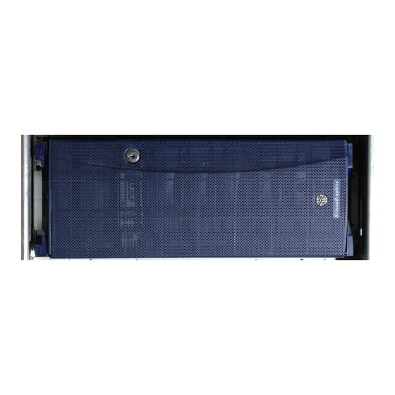
Chapter 5 Origin200 Cosmetic Features and Covers This chapter describes the covers, doors, and other cosmetic features of the Origin200 server: • “Locking the System” on page 113 • “Adjusting the Feet” on page 115 • “Removing the Front Door” on page 116 •... -
Page 140: Locking The Chassis
Chapter 5: Origin200 Cosmetic Features and Covers Locking the Chassis To lock the chassis, use the two metal tabs that are provided with the system. Figure 5-1 provides an overview of the process. Figure 5-1 Locking the Chassis With the Locking Tabs Follow these steps to lock the chassis (refer to Figure 5-1). -
Page 141: Adjusting The Feet
Adjusting the Feet Adjusting the Feet Both the front and rear feet on an Origin200 server in a tower configuration can be swiveled in or out. See Figure 5-2. Adjusting the Feet Figure 5-2 To adjust the feet: 1. Raise the server slightly, or tilt it to one side. -
Page 142: Removing The Front Door
Chapter 5: Origin200 Cosmetic Features and Covers Removing the Front Door The front door of an Origin200 server has several features: • In a tower configuration, the door is designed to release from its hinges if it is struck while open, or otherwise forced too far open. -
Page 143: Figure 5-4 Removing The Front Door, Rackmount Configuration
Removing the Front Door To remove the front door in a rackmount configuration, follow these steps: 1. Lift the door assist tab (catch), as shown in Figure 5-4. 2. Pull one side of the door off its hinge. Figure 5-4 Removing the Front Door, Rackmount Configuration... -
Page 144: Removing The System Cover And Chassis Access Door
Chapter 5: Origin200 Cosmetic Features and Covers Removing the System Cover and Chassis Access Door Caution: Because of the weight of an Origin200 system, two people are required to lift and move the chassis. To remove the system cover and chassis access panel of an Origin200 server, follow these steps: 1. -
Page 145: Figure 5-5 Removing The System Cover, Tower Origin200 System
Swing the door out, away from the chassis. Optional: You can remove the door by lifting it up slightly and away from the chassis. In some cases, it may be easier to service the Origin200 if you remove the chassis access door. -
Page 146: Figure 5-6 Opening The Chassis Access Door, Tower Origin200 System
Chapter 5: Origin200 Cosmetic Features and Covers Figure 5-6 Opening the Chassis Access Door, Tower Origin200 System... -
Page 147: Removing The Side Panel, Feet, And Exterior Plastic Parts Of A Tower System
If desired, you can remove the feet, system cover, side panel, and most of the exterior plastic parts from an Origin200 server in a tower configuration. With the addition of rackmounting ears, you can then mount the server in a standard, 19-inch equipment rack. -
Page 148: Removing The Feet And Exterior Plastic Parts
Chapter 5: Origin200 Cosmetic Features and Covers Removing the Feet and Exterior Plastic Parts Follow these steps to remove the feet, top cap, and lower bezel: 1. Remove the top cap, as shown in Figure 5-7. Insert a flat-blade screwdriver between the top cap and sheet metal, as shown in Figure 5-7. -
Page 149: Figure 5-8 Removing The Lower Bezel
Removing the Side Panel, Feet, and Exterior Plastic Parts of a Tower System 2. Remove the lower bezel. Insert a flat-blade screwdriver between one side of the lower bezel and the sheet metal, as shown in Figure 5-8. Twist the screwdriver to disengage the lower bezel from the sheet metal. Pull off the lower bezel. -
Page 150: Figure 5-9 Removing The Pedestal Assembly (Feet)
Chapter 5: Origin200 Cosmetic Features and Covers 3. Remove the pedestal assembly (to which the feet are attached). See Figure 5-9. Place the system on its side on a sturdy work surface capable of supporting at least 40 pounds (18 kg) and up to 75 pounds (34 kg). Be careful not to scratch or damage the front bezel. -
Page 151: Installing And Removing Memory
Chapter 6 Installing and Removing Memory This chapter describes how to install and remove memory. -
Page 153: Installing And Removing Memory
This chapter describes how to install and remove dual in-line memory modules (DIMMs) in a Origin200 server: • “Handling Precautions” on page 127 • “About Origin200 Memory” on page 128 • “Installing Memory” on page 128 • “Verifying That Installed Memory Is Recognized by the System” on page 133 •... -
Page 154: About Origin200 Memory
Each module must have memory installed (32 MB minimum per module). Installing Memory Follow these steps to install memory in an Origin200 server. 1. Shut down the system completely. See “Turning Off the System” in Chapter 4. Be sure to turn off the master power switch. -
Page 155: Figure 6-1 Attaching A Grounding Wrist Strap
4. Attach a grounding strap to your wrist as shown on the wrist-strap package, and in Figure 6-1. All Silicon Graphics options, including memory, are shipped with wrist straps to help prevent damage to components from static electricity. Figure 6-1... -
Page 156: Figure 6-2 Locating Dimms In The Origin200 Server
Chapter 6: Installing and Removing Memory 5. Locate the DIMM slots. See Figure 6-2. DIMM banks Figure 6-2 Locating DIMMs in the Origin200 Server... -
Page 157: Figure 6-3 How Dimm Pairs Are Grouped In The Origin200 Server
Rear of system Figure 6-3 How DIMM Pairs Are Grouped in the Origin200 Server Figure 6-3 shows one pair of DIMMs installed in bank 0 (all modules must have memory in bank 0; if you have a two-module system, both must have memory in bank 0). -
Page 158: Figure 6-4 Installing A Dimm
Chapter 6: Installing and Removing Memory Figure 6-4 shows how to insert a DIMM into its socket. Figure 6-4 Installing a DIMM As you lower the DIMM into its socket, press down first on one side then the other to seat the DIMM (upper drawing). Press straight down across the entire top to make sure the DIMM is firmly seated. -
Page 159: Verifying That Installed Memory Is Recognized By The System
Verifying That Installed Memory Is Recognized by the System 7. After you have finished installing DIMMs, remove your wrist strap and reassemble the system. Replace the chassis access door and side panel (the reverse of removing them). Reattach the cables to the back of the system. You are now ready to verify that the memory is recognized by the system. -
Page 160: Removing Memory
Chapter 6: Installing and Removing Memory Removing Memory Follow these steps to remove memory from an Origin200 server. 1. Shut down the system completely. See “Turning Off the System” in Chapter 4. Be sure to turn off the master power switch. -
Page 161: Figure 6-5 Attaching A Grounding Wrist Strap
Removing Memory 4. Attach a grounding strap to your wrist. Figure 6-5 shows an example of a disposable grounding strap. Attaching a Grounding Wrist Strap Figure 6-5... -
Page 162: Figure 6-6 Locating Dimms In The Origin200 Server
Chapter 6: Installing and Removing Memory 5. Locate the DIMMs. See Figure 6-6. DIMM banks Locating DIMMs in the Origin200 Server Figure 6-6... -
Page 163: Figure 6-7 How Dimm Pairs Are Grouped In Origin200
Rear of system Figure 6-7 How DIMM Pairs Are Grouped In Origin200 Start by removing bank 3, then bank 2, then bank 1. Do not skip banks. You must have at least one bank of memory installed in both modules in order for the system to operate. -
Page 164: Figure 6-8 Removing Dimms
Chapter 6: Installing and Removing Memory Figure 6-8 Removing DIMMs... - Page 165 Removing Memory Press down on the release lever for the DIMM you want to remove. The lever raises the DIMM out of that side of its socket. Grasp the DIMM along the edges and pull it up out of its socket with an end-to-end rocking motion.
- Page 167 Chapter 7 Installing and Removing PCI Option Boards This chapter describes how to install and remove PCI option boards.
-
Page 169: Installing And Removing Pci Option Boards
Chapter 7 Installing and Removing PCI Option Boards This chapter describes how to install and remove PCI option boards in an Origin200 server: • “Handling Precautions” on page 143 • “Installing a PCI Option Board” on page 144 • “Removing a PCI Option Board” on page 152 Handling Precautions Option boards are sensitive to electrostatic discharge (ESD). -
Page 170: Installing A Pci Option Board
Chapter 7: Installing and Removing PCI Option Boards Installing a PCI Option Board The following steps describe how to install a PCI option board into an Origin200 server. 1. Shut down the system completely. See “Turning Off the System” in Chapter 4. -
Page 171: Figure 7-1 Attaching A Grounding Wrist Strap
Attach a grounding strap to your wrist as shown on the wrist-strap package, and in Figure 7-1. All Silicon Graphics options, including PCI boards, are shipped with wrist straps to help prevent damage to components from static electricity. Figure 7-1... -
Page 172: Figure 7-2 Locating The Pci Option Slots
Chapter 7: Installing and Removing PCI Option Boards 4. Locate an available PCI option slot. See Figure 7-2. Although you can install a PCI board in any open slot, you may observe better I/O performance if you install boards starting in order with slot 5, particularly if the PCI board you are installing can perform prefetching. -
Page 173: Figure 7-3 Removing A Pci Slot Blanking Plate
Installing a PCI Option Board 5. Remove the blanking plate from the slot. Using a #2 Phillips screwdriver, remove the single screw that secures the blanking plate to the chassis. See Figure 7-3. Remove the blanking plate by lifting it straight up, as shown in Figure 7-3. Figure 7-3 Removing a PCI Slot Blanking Plate... -
Page 174: Figure 7-4 Example Pci Board With Feature Connectors
To install such a board in an Origin200 server, you must install a cable from a connector on the board to the feature connector on the PCI backplane. If you are not sure if the PCI board you are installing uses a feature connector, refer to Figure 7-4. -
Page 175: Figure 7-5 Attaching A Feature Connector Cable To The Pci Backplane
Locate the feature-connector cable in the PCI board shipment. See Figure 7-5. Attach one end of the feature-connector cable to the connector next to the desired PCI slot on the Origin200 PCI backplane, as shown in Figure 7-5. Feature-connector cable... -
Page 176: Figure 7-6 Attaching A Feature Connector Cable To The Pci Board
Chapter 7: Installing and Removing PCI Option Boards Connect the other end of the cable to the Origin200 feature connector, as shown in Figure 7-6. Figure 7-6 Attaching a Feature Connector Cable to the PCI Board 7. Install the PCI option board in the PCI slot. -
Page 177: Figure 7-7 Securing The Pci Option Board To The Chassis
Installing a PCI Option Board Be careful not to kink or damage the flexible EMI gasket that surrounds the inside of the rear chassis wall. Attach the screw that secures the PCI option board to the chassis, as shown in Figure 7-7. -
Page 178: Removing A Pci Option Board
Replace the chassis access door and side panel (the reverse of removing them). Reattach the cables to the back of the system. Do not discard the blanking plate that you removed from the Origin200 chassis. If Note: you ever decide to remove the PCI option board, you must replace this blanking plate to ensure proper airflow through the Origin200 chassis. -
Page 179: Figure 7-8 Attaching A Grounding Wrist Strap
Removing a PCI Option Board 4. Attach a grounding strap to your wrist. Figure 7-8 shows an example of a disposable grounding strap. Figure 7-8 Attaching a Grounding Wrist Strap... -
Page 180: Figure 7-9 Removing A Pci Option Screw And Board
5. Locate the PCI option board you wish to remove. 6. Remove the board. Using a #2 Phillips screwdriver, remove the screw that secures the PCI option board to the Origin200 chassis, as shown in Figure 7-9. Removing a PCI Option Screw and Board Figure 7-9... -
Page 181: Figure 7-10 Replacing A Pci Option Blanking Plate And Screw
7. Replace the blanking plate. Align the blanking plate and slide it in place, as shown in Figure 7-10. Attach the screw that secures the blanking plate to the Origin200 chassis, as shown in Figure 7-10. Figure 7-10... - Page 182 Replace the chassis access door and side panel (the reverse of removing them). Reattach the cables to the back of the system. You must replace the blanking plate to cover the gap in the rear of the Origin200 Note: chassis in order to ensure proper airflow through the chassis.
- Page 183 Chapter 8 Installing and Configuring Peripherals This chapter describes how to install and configure internal and external peripherals. These include 5.25-inch and 3.5-inch drives and serial devices.
-
Page 185: Installing And Configuring Peripherals
• “Verifying That a Drive Is Installed Correctly” on page 179 • “Using Drives In the Origin200 Server” on page 179 • “Attaching Serial Devices” on page 181 This chapter also directs you to additional documentation about using peripherals with your Origin200 system. -
Page 186: About The 5.25-Inch Peripheral Bay
Chapter 8: Installing and Configuring Peripherals About the 5.25-Inch Peripheral Bay The 5.25-inch drive bay is located at the top of the Origin200 in a tower configuration, or on the left-hand side in a rackmount configuration. Figure 8-1 shows the location of the 5.25-inch drive bay. -
Page 187: Configuring A 5.25-Inch Peripheral
Installing, Removing, and Configuring 5.25-Inch Peripherals Configuring a 5.25-Inch Peripheral Peripherals obtained from Silicon Graphics are preconfigured. You can install them in the 5.25-inch drive bay with no additional configuration. However, if you are installing third-party peripherals, or wish to change the configuration of a Silicon Graphics-supplied drive, follow these guidelines:... -
Page 188: Figure 8-2 Removing The 5.25-Inch Peripheral Carrier
Chapter 8: Installing and Configuring Peripherals Figure 8-2 Removing the 5.25-Inch Peripheral Carrier 3. Prepare the peripheral carrier, as shown in Figure 8-3. Remove one or two of the blanking plates from the front of the carrier, depending upon the height of the drive you are installing. Using a #2 Phillips screwdriver, remove the screws that hold the access plate to the rear of the carrier, then remove the access plate. -
Page 189: Figure 8-3 Removing A Blanking Plate And The Rear Access Plate
Installing, Removing, and Configuring 5.25-Inch Peripherals Front Rear Removing a Blanking Plate and the Rear Access Plate From the Peripheral Carrier Figure 8-3 4. Slide the drive into the peripheral carrier and attach it with four screws through the side of the carrier, as shown in Figure 8-4. 5. -
Page 190: Figure 8-4 Installing A 5.25-Inch Drive In The Peripheral Carrier
Chapter 8: Installing and Configuring Peripherals Front Rear Rear Installing a 5.25-Inch Drive in the Peripheral Carrier Figure 8-4 7. Slide the carrier into the system and secure it with the two captive screws. See Figure 8-5. -
Page 191: Figure 8-5 Replacing The 5.25-Inch Peripheral Carrier
Installing, Removing, and Configuring 5.25-Inch Peripherals Replacing the 5.25-Inch Peripheral Carrier Figure 8-5 8. Replace the front door. You are finished installing the 5.25-inch peripheral. -
Page 192: Removing 5.25-Inch Peripherals
Using a #2 Phillips screwdriver, undo the two captive screws that secure the peripheral carrier to the Origin200 chassis. Grasp the handle of the peripheral carrier and pull the carrier out of the 5.25-inch drive bay. -
Page 193: Figure 8-7 Removing The Rear Access Plate From The Peripheral Carrier
Installing, Removing, and Configuring 5.25-Inch Peripherals 3. Remove the rear access plate from the peripheral carrier, as shown in Figure 8-7. Using a #2 Phillips screwdriver, remove the screws that hold the access plate to the rear of the carrier, then remove the access plate. Rear Figure 8-7 Removing the Rear Access Plate From the Peripheral Carrier... -
Page 194: Figure 8-8 Removing A Drive From The Peripheral Carrier
Chapter 8: Installing and Configuring Peripherals 5. Remove the screws that hold the drive to the peripheral carrier and remove the drive from the carrier, as shown in Figure 8-8. Front Figure 8-8 Removing a Drive From the Peripheral Carrier 6. -
Page 195: Figure 8-9 Replacing The Front Blanking Plate And Rear Access Plate
Installing, Removing, and Configuring 5.25-Inch Peripherals Front Rear Figure 8-9 Replacing the Front Blanking Plate and Rear Access Plate... -
Page 196: Figure 8-10 Replacing The 5.25-Inch Peripheral Carrier
Chapter 8: Installing and Configuring Peripherals 7. Slide the carrier into the system and secure it with the two captive screws. See Figure 8-10. Replacing the 5.25-Inch Peripheral Carrier Figure 8-10... -
Page 197: Installing, Removing, And Configuring 3.5-Inch Peripherals
You are finished removing the 5.25-inch peripheral. Installing, Removing, and Configuring 3.5-Inch Peripherals The Origin200 chassis has room for six 3.5-inch peripherals. Each peripheral is mounted on a sled to make it convenient to install and remove, and set their SCSI ID numbers. -
Page 198: Figure 8-11 The 3.5-Inch Drive Bay And Correspondence Of Scsi Ids To Drive Sots
Chapter 8: Installing and Configuring Peripherals Slot 6 (SCSI ID 6) Slot 1 (SCSI ID 1) Figure 8-11 The 3.5-Inch Drive Bay and Correspondence of SCSI IDs to Drive Sots Drive bays that do not contain peripherals are covered by blanking plates. Figure 8-12 shows a blanking plate for the 3.5-inch drive bay. -
Page 199: Configuring 3.5-Inch Peripherals
Installing, Removing, and Configuring 3.5-Inch Peripherals Configuring 3.5-Inch Peripherals 3.5-inch peripherals obtained from Silicon Graphics are preconfigured and installed on drive sleds. You can install them in the 3.5-inch drive bay with no additional configuration. Installing a 3.5-Inch Peripheral Follow these steps to install a 3.5-inch peripheral: 1. -
Page 200: Figure 8-14 How The 3.5-Inch Drives Are Numbered In An Origin200 System
Slot 6 (SCSI ID 6) Slot 1 (SCSI ID 1) Figure 8-14 How the 3.5-inch Drives are Numbered in an Origin200 System 3. Install the peripheral. If there is a plastic blanking plate covering the slot, remove it as shown in Figure 8-15. -
Page 201: Figure 8-15 Installing A 3.5-Inch Peripheral In An Origin200 System
Save the blanking plates you remove. If you ever remove a peripheral and do not Note: replace it with another one, you should reinstall the blanking plate to ensure proper cooling air flow and electromagnetic interference (EMI) shielding in the Origin200 chassis. -
Page 202: Removing A 3.5-Inch Peripheral
Chapter 8: Installing and Configuring Peripherals Removing a 3.5-Inch Peripheral Follow these steps to remove a 3.5-inch peripheral: 1. Open the front door of the chassis, as shown in Figure 8-16. Figure 8-16 Opening the Front Door of an Origin200 System... -
Page 203: Figure 8-17 How The 3.5-Inch Drives Are Numbered In An Origin200 System
Slot 6 (SCSI ID 6) Slot 1 (SCSI ID 1) Figure 8-17 How the 3.5-inch Drives Are Numbered in an Origin200 System 3. Remove the drive, as shown in Figure 8-18. Pull the locking lever down. Grasp the lever and pull the drive straight out of the chassis. -
Page 204: Figure 8-18 Removing A 3.5-Inch Drive From An Origin200 Server
Chapter 8: Installing and Configuring Peripherals Removing a 3.5-inch Drive from an Origin200 Server Figure 8-18 4. If you are not replacing the drive with another peripheral, cover the open slot with a plastic blanking plate, as shown in Figure 8-18. -
Page 205: Verifying That A Drive Is Installed Correctly
2) and no drives installed in channel 1. Using Drives In the Origin200 Server Once installed, Silicon Graphics-provided peripherals are all recognized by the operating system (IRIX) and are ready to be configured for use with the system. Table 8-1 indicates where to turn for more information about configuring drives, depending upon... -
Page 206: Table 8-1 Sources Of Information For Drive Configuration
Chapter 8: Installing and Configuring Peripherals In addition to the reference pages described in Table 8-1, refer to IRIX Admin: Disks and Filesystems. See “About This Guide” in this manual for information about obtaining additional manuals and documentation. Table 8-1 Sources of Information for Drive Configuration Type of Configuration/Operation Man Pages or Tools... -
Page 207: Attaching Serial Devices
Attaching Serial Devices Attaching Serial Devices Each Origin200 module provides connectors for two serial ports at the rear of the chassis. Figure 8-19 shows the locations of the connectors for these ports. Serial port connector 2 Serial port connector 1... -
Page 208: Table 8-2 Serial Port Numbers And Correspondence To Irix Device Files
DB9, male, and are designed to be IBM-compatible. Because of this, they do not use the same pinouts as DB9 serial ports on older Silicon Graphics systems. Table 8-2 shows the correspondence of ports to IRIX device files and protocols. -
Page 209: Attaching Serial Cables
Attaching Serial (ASCII) Terminals You can connect an optional ASCII terminal to your Origin200 by using the serial cable shipped with your server. It has a DB9 connector on one end and a 25-pin serial connector on the other. See Appendix B, “Cable Descriptions” for information on this cable. - Page 210 Chapter 8: Installing and Configuring Peripherals In some cases the terminal may need special recognition from the system software. You can check or set up the system software to work under specific parameters by following these steps: 1. Log in to the system as root. 2.
- Page 211 Attaching Serial Devices 5. Look in /etc/ttytype for the listed console port information. You should see lines similar to this: ?iris-tp console iris-tp tport ?vt100 ttyd1 ?vt100 ttym1 ?vt100 ttyf1 ?vt100 ttyd2 ?vt100 ttym2 ?vt100 ttyf2 ?vt100 ttyd3 ?vt100 ttym3 ?vt100 ttyf3 6.
-
Page 212: Connecting A Modem
Chapter 8: Installing and Configuring Peripherals If the test sentence appears on the terminal screen, but you do not see a “login:” prompt when you press the terminal’s Enter key, verify that there is a getty process running on the serial port. ps -def | grep getty You should see output similar to this: root... -
Page 213: Useful Serial Commands
Attaching Serial Devices 6. Read the documentation that comes with your modem to determine model-specific connection and configuration procedures. For additional information about configuring modems, see IRIX Admin: Peripheral Devices. You may need to modify entries in the files /etc/inittab and /etc/uucp/Devices. Additional useful information on modem operation and configuration is available on the cu(1) reference page. - Page 214 Chapter 8: Installing and Configuring Peripherals The following files are commonly used to configure serial port operation for the Origin200 server: • /etc/inittab • /etc/gettydefs • /etc/ttytype • /usr/lib/terminfo • /etc/uucp/Devices • /etc/uucp/Systems...
-
Page 215: Troubleshooting And Maintenance
Chapter 9 Troubleshooting and Maintenance This chapter describes the various LED codes displayed by an Origin200 server, how to check the power supply, and what regular maintenance is required. -
Page 217: Troubleshooting And Maintenance
Chapter 9 Troubleshooting and Maintenance This chapter contains the following sections: • “Status LED Messages” on page 191 • “Ethernet Status LED Messages” on page 193 • “Regular Maintenance” on page 193 Status LED Messages The status LED on the front panel can display three colors: green, amber, red. (See “Front Panel Functions: Status LED, Power, Reset, NMI”... -
Page 218: Table 9-1 Status Led Messages
Chapter 9: Troubleshooting and Maintenance Table 9-1 Status LED Messages LED Code Meaning Corrective Action Red briefly, then amber, If you have just turned on the then green, then off master power switch, this indicates (about 1/2 second per color) the system controller is OK. -
Page 219: Ethernet Status Led Messages
Regular Maintenance The only regular maintenance that the Origin200 server requires is periodic cleaning to remove any dust accumulation. Because the server is designed to be operated in a typical office computing environment that is relatively dust-free, there are no air filters in the system. - Page 220 Vacuum off any visible dust, then replace the chassis access door and side panel. See Chapter 5, “Origin200 Cosmetic Features and Covers,” for information about removing the system cover and chassis access door. See Chapter 10, “Removing and Replacing Internal Components,”...
- Page 221 Chapter 10 Removing and Replacing Internal Components This chapter describes how to remove and replace internal components of an Origin200 server.
-
Page 223: Removing And Replacing Internal Components
Chapter 10 Removing and Replacing Internal Components This chapter describes how to remove and replace internal components of an Origin200 system: • “Tools Required to Remove and Replace Components” on page 197 • “Miscellaneous Fasteners” on page 198 • “Removing and Replacing Internal Parts” on page 198, which contains –... -
Page 224: Miscellaneous Fasteners
Chapter 10: Removing and Replacing Internal Components Miscellaneous Fasteners The following miscellaneous fasteners are used in the Origin200 server: • plastic rivets to attach the fans to the fan bulkhead; spare rivets are included with replacement fans from Silicon Graphics •... -
Page 225: Preparing The Origin200 For Servicing
CrayLink Interconnect, Ethernet, and so on). 4. Place the system on its side on a flat work surface. Caution: Two people are required to lift and move the Origin200 server. If the system is mounted in an equipment rack, remove it according to the instructions in “Removing a Server From an Equipment Rack,”... -
Page 226: Replacing The Scsi Backplane
Replacing the SCSI Backplane If you have not done so already, follow the procedures in “Preparing the Origin200 for Servicing” to make sure the system is opened up and ready to work on. -
Page 227: Figure 10-2 Cable Connections And Spring Clips On The Scsi Backplane
Removing and Replacing Internal Parts 1. Remove any 3.5-inch drives from the drive bays. 2. Detach the power cables from the SCSI backplane. Note that the power cable plugs differ from each other. Figure 10-2 shows their locations. If you are able, detach the SCSI cable from its connector; otherwise, wait until the backplane is partway out of the chassis. -
Page 228: Installing A New Scsi Backplane
5. Snap the six spring clips back up into place. Replacing Fans If you have not done so already, follow the procedures in “Preparing the Origin200 for Servicing” to make sure the system is opened up and ready to work on. Once you have opened the Origin200 chassis, follow these steps to remove a fan: 1. -
Page 229: Figure 10-3 Disconnecting The Fan And Fan Power Cable (Other Components Removed For Clarity)
Removing and Replacing Internal Parts Fan 3 Fan 2 Fan 1 Disconnecting the Fan and Fan Power Cable (Other Components Removed Figure 10-3 for Clarity) -
Page 230: Installing A New Fan
Chapter 10: Removing and Replacing Internal Components 3. Lift the fan out of the system, as shown in Figure 10-4. Figure 10-4 Removing the Fan From the System Installing a New Fan Follow these steps to install a fan: 1. Lower the new fan into the system. 2. -
Page 231: Replacing The Logic Carrier
Removing and Replacing Internal Parts Replacing the Logic Carrier If you have not done so already, follow the procedures in “Preparing the Origin200 for Servicing” to make sure the system is opened up and ready to work on. Once you have opened the Origin200 chassis, follow these steps to remove the logic carrier: 1. -
Page 232: Figure 10-6 Removing The Pci Plenum Divider
Chapter 10: Removing and Replacing Internal Components 3. Lift the PCI plenum divider sheetmetal out of the system, as shown in Figure 10-6. Figure 10-6 Removing the PCI Plenum Divider... -
Page 233: Figure 10-7 Disconnecting Cables From The Logic Carrier
Removing and Replacing Internal Parts 4. Disconnect the cables that are attached to the logic carrier, as shown in Figure 10-7. Detach the two SCSI cables. Disconnect the power connector. Remove the system controller cable. Disconnect the PCI power cable. Figure 10-7 Disconnecting Cables from the Logic Carrier... -
Page 234: Figure 10-8 Unfastening The Logic Carrier
Chapter 10: Removing and Replacing Internal Components 5. Unfasten the captive screws and sheet metal screws that secure the logic carrier. See Figure 10-7. Unfastening the Logic Carrier Figure 10-8... -
Page 235: Figure 10-9 Removing The Logic Carrier
Removing and Replacing Internal Parts 6. Lift the logic carrier out of the system, as shown in Figure 10-9. Grasp the logic carrier handle with one hand and the connector panel with the other. As you lift the logic carrier, tilt the side with the CPU daughter card up slightly higher than the side with the PCI backplane. -
Page 236: Installing A New Logic Carrier
Chapter 10: Removing and Replacing Internal Components Installing a New Logic Carrier Follow these steps to replace the logic carrier. 1. Lower the new logic carrier into the system, as shown in Figure 10-10. Figure 10-10 Lowering A Logic Carrier Into the System... -
Page 237: Figure 10-11 Fastening The Logic Carrier
Removing and Replacing Internal Parts 2. Secure the logic carrier by tightening the captive fasteners and installing the sheet metal screws, as shown in Figure 10-11. Figure 10-11 Fastening the Logic Carrier... -
Page 238: Figure 10-12 Attaching The Logic Carrier Cables
Chapter 10: Removing and Replacing Internal Components 3. Attach the power, SCSI, and system controller cables to the logic carrier, as shown in Figure 10-12. Figure 10-12 Attaching the Logic Carrier Cables... -
Page 239: Figure 10-13 Installing The Pci Plenum Divider
Removing and Replacing Internal Parts 4. Install the PCI plenum divider sheet metal as shown in Figure 10-13. Be extremely careful not to pinch the SCSI cables when installing the PCI plenum divider. Make sure that the SCSI cables are not underneath the plenum divider captive screw. -
Page 240: Figure 10-14 Fastening The Pci Plenum Divider
Chapter 10: Removing and Replacing Internal Components 5. Fasten the PCI plenum divider by tightening the captive screw and installing the sheet metal screw, as shown in Figure 10-14. Fastening the PCI Plenum Divider Figure 10-14 You are finished replacing the logic carrier. You can now reinstall any PCI option boards that were present in the system, and return the system to working order. -
Page 241: Replacing The Power Supply
Removing and Replacing Internal Parts Replacing the Power Supply If you have not done so already, follow the procedures in “Preparing the Origin200 for Servicing” to make sure the system is opened up and ready to work on. Once you have opened the Origin200 chassis, follow these steps to remove the power supply: Follow these steps to replace the power supply. -
Page 242: Installing A New Power Supply In The Origin200 Server
Figure 10-16 Installing a New Power Supply In the Origin200 Server Follow these steps to install a new power supply in an Origin200 server: 1. Lower the power supply into the chassis with the power switch and receptacle towards the rear of the system. -
Page 243: Figure 10-17 Location Of Origin200 Server Power Supply Screws
3. Install the screws at the rear of the system, as shown in Figure 10-17. • Six screws secure the power supply to the chassis. Location of Origin200 Server Power Supply Screws Figure 10-17 4. Reconnect some of the cables: fan power cables, SCSI drive power cable, module system controller cable. -
Page 244: Replacing The Module System Controller
For this procedure, you do not have to follow the instructions in “Preparing the Note: Origin200 for Servicing.” The module system controller can be removed with the system in place and fully assembled. The module system controller (MSC) is mounted on a sheet-metal carrier to form a single, assembly. -
Page 245: Figure 10-18 Removing The Front Bezel Crossbar
Removing and Replacing Internal Parts Figure 10-18 Removing the Front Bezel Crossbar 4. Using a #2 Phillips screwdriver, remove the two screws that fasten the system controller assembly to the chassis, as shown in Figure 10-19. -
Page 246: Figure 10-19 Removing The System Controller Assembly From The Chassis
Chapter 10: Removing and Replacing Internal Components System Controller Figure 10-19 Removing the System Controller Assembly From the Chassis 5. Pull out the system controller assembly and lay it on a flat worksurface. Caution: To prevent ESD damage to the module system controller, be careful not to touch the board’s edge connectors (gold fingers). -
Page 247: Figure 10-20 Removing The Module System Controller Board From Its Carrier
Removing and Replacing Internal Parts 6. Remove the system controller board from its carrier; it is secured by a screw and two pins, as shown in Figure 10-20. Using a #2 Phillips screwdriver, remove the screw. Slide the board on the carrier until you can lift the board off the pins. Pins Screw Figure 10-20... -
Page 248: Figure 10-21 Removing The Nic From The Module System Controller
See Figure 10-21. The NIC stores the system serial number and should stay with your original Origin200 server. Slide the NIC out of its socket and put it aside. You will install the NIC in the replacement module system controller. -
Page 249: Installing A New Module System Controller
3. Remove the disks (or blanking plates if no disks are installed) from slots 5 and 6 of the Origin200 server. Removing the disks (or blanking plates) allows you to see how the edge connector on the module system controller board aligns with its socket inside the chassis. - Page 251 Appendix A Appendices These appendices include information about connector pinouts, cables, and supported terminals.
-
Page 253: Connector Pinout Assignments
Appendix A Connector Pinout Assignments This appendix describes the pinouts of the following external connectors on an Origin200 server: • “Serial Ports” on page 227 • “Parallel Port” on page 229 • “Ethernet Port” on page 231 • “AUX Port” on page 232 (module system controller) •... -
Page 254: Table A-1 Origin200 Serial Port Pin Assignments, Rs-232 Mode
Appendix A: Connector Pinout Assignments Table A-1 shows the connector pin assignments for the serial ports in RS-232 mode. Table A-1 Origin200 Serial Port Pin Assignments, RS-232 Mode Assignment Data Carrier Detect (DCD) Receive Data (RXD) Transmit Data (TXD) Data Terminal Ready (DTR) -
Page 255: Parallel Port
Parallel Port Parallel Port Figure A-2 Origin200 Parallel Port Pinout Assignments The Origin200 parallel port uses a 36-pin Centronics connector (IEEE 1284-C). Table A-3 shows the connector pinout assignments for the parallel port. Table A-3 Origin200 Parallel Port Pin Assignments... - Page 256 Appendix A: Connector Pinout Assignments Table A-3 (continued) Origin200 Parallel Port Pin Assignments Assignment BUSY ONLINE PR/SC NOPAPER (Not Connected) NOINK (Not Connected) 19–30 Signal Ground (GND) RESET 32–36 (Not Connected)
-
Page 257: Ethernet Port
Ethernet Port Ethernet Port Transmit (green) Packet detect (yellow) Figure A-3 Origin200 Ethernet 10-Base-T/100-Base-TX Port Pinout Assignments Table A-4 shows the connector pinout assignments for the Ethernet 10-Base-T/100-Base-TX port. Table A-4 Origin200 Ethernet 10-Base-T/100-Base-TX Port Pin Assignments Assignment Transmit + Transmit –... -
Page 258: Aux Port
Appendix A: Connector Pinout Assignments AUX Port Origin200 AUX Port Pinout Assignments Figure A-4 The AUX port is used to communicate with the module system controller (MSC). You can attach a serial (ASCII) terminal to the port, or attach a modem for remote access. -
Page 259: External Interrupt Ports
The external interrupt interface uses two 1/8” (3.5 mm) stereo jacks: one to generate interrupts and one to receive interrupts. The jacks are located on the back of the Origin200 server and are wired as indicated in Table A-6: Table A-6... -
Page 261: Cable Descriptions
The cable described in this section attaches a printer or a character (ASCII) terminal to the Origin200 server. The server ships with a cable of this type, and you can purchase an additional or replacement cable from Silicon Graphics or your local service provider. - Page 262 Appendix B: Cable Descriptions Table B-1 shows the cable connector pin assignments. Table B-1 Connector Pin Assignments for Printer/Character (ASCII) Terminal Serial Cable Pin Number Pin Number Signal (DB9 Female) (DB25) N/C (not connected) Receive Data (RXD) Transmit Data (TXD) Ground (GND)
-
Page 263: Modem Cable (Full-Handshake)
(except printers and terminals) that do not need RTS/CTS flow control, and you can use it with a null modem adapter to attach printers and character terminals. You can purchase this full-handshake serial cable from Silicon Graphics or from your local service provider. -
Page 264: Origin200 To Indy And Indigo Cable (Db9 To Din-8)
This serial cable connects Silicon Graphics Indy and Indigo workstations to an Origin200 system. Table B-3 shows the cable connector pin assignments. Table B-3 Connector Pin Assignments for an Origin200 to Indy and Indigo Serial Cable Pin Number Signal Pin Number... -
Page 265: Origin200 To O2, Onyx2, And Ibm Compatible (Db9 To Db9)
Serial Cables Origin200 to O2, Onyx2, and IBM Compatible (DB9 to DB9) This serial cable connects an Origin200 to Silicon Graphics O2 and Onyx2 workstations, and IBM compatibles with a DB9 serial port. Table B-4 shows the cable connector pin assignments. -
Page 266: Origin200 To Onyx (Db9 To Db9)
Appendix B: Cable Descriptions Origin200 to Onyx (DB9 to DB9) This serial cable connects an Onyx to the Origin200. Notice that the Onyx DB9 pin assignments are different from the Origin200 DB9 pin assignments. Table B-5 shows the cable connector pin assignments. -
Page 267: Origin200 To Macintosh Cable (Db9 To Din-8)
Serial Cables Origin200 to Macintosh Cable (DB9 to DIN-8) This cable connects any Macintosh computer to an Origin200 system. Table B-6 shows the cable connector pin assignments. Table B-6 Connector Pin Assignments for an Origin200 to Macintosh Serial Cable Pin Number... -
Page 268: Aux Port Cables
AUX Port Terminal Cable The cable described in this section connects the Origin200 AUX port to a terminal. Note that this cable is identical to the one used to attach a terminal to a Silicon Graphics Indy, Indigo, or Indigo workstation and CHALLENGE S server. -
Page 269: Aux Port Modem Cable
AUX Port Modem Cable The cable described in this section connects the Origin200 AUX port to a modem. Note that this cable is identical to the one use to attach a modem to a Silicon Graphics Indy, Indigo, or Indigo workstation and CHALLENGE S server. -
Page 271: Supported Terminals
Appendix C Supported Terminals The terminfo terminal description database provides support for over 1600 variations of character-based terminals from a wide variety of manufacturers. This appendix lists a few of the terminals supported under IRIX. For a complete list of supported terminals, examine the subdirectories of /usr/lib/terminfo. - Page 273 Glossary 100-Base-TX Twisted-pair variant of 100BASE-X. Uses the physical characteristics of FDDI’s TP-PMD, but uses Ethernet framing and CSMA/CD. Used in Silicon Graphics Origin and Onyx2 systems. 100-Base-X 100Mbps CSMA/CD 802.3/Ethernet-like LAN also known as Fast Ethernet. There are two types: 100BASE-TX (used in Silicon Graphics Origin and Onyx2 systems) and 100BASE-T4.
- Page 274 Glossary Error correction code; used in memory to correct for single-bit errors. electromagnetic interference (EMI) Electromagnetic radiation that is produced by electronic equipment, and that can interfere with radio and television reception and cause problems with other electronic devices. Computer equipment is designed to contain EMI to various extents as determined by regulatory agencies.
- Page 275 (NIC) A device mounted on a circuit board that contains information such as the serial number of the board and other information. In Origin200 systems, the NIC mounted on the module system controller contains the system serial number.
- Page 276 Small computer systems interface. See also channel and controller. system A general term for all the components of a computer. In the case of Origin200, the system consists of one or more nodes as well as the software installed on them. See also node.
-
Page 277: Index
CrayLink Interconnect Ethernet grounding cable Origin200 to Indy and Indigo power cables Origin200 to Macintosh serial devices 181, 183 Origin200 to O2, Onyx2, and IBM-compatible AutoLoad variable, setting Origin200 to Onyx automatic power-on power serial 183, 235 AUX port wiring descriptions of... - Page 278 Index chassis clearances cooling air flow through system clearance around the chassis heat dissipation (maximum) commands maximum air flow apropos xxvi CPU daughter card 94, 187 in logic carrier emacs /etc/ioconfig CrayLink Interconnect, using to connect two for use with disks modules 52-56 for use with serial ports...
- Page 279 (DIMM). See memory. LED messages about 24, 191 locations operating speeds removing speed and air temperature ears fasteners used in an Origin200 system rackmounting hardware 64-67 feet earthing. See grounding. adjusting (swiveling) emacs files end caps, attaching to rackmounted chassis...
- Page 280 NMI button power switch removing reset button status LED 76, 191 IBM compatible Origin200 to IBM compatible cable front power switch 58, 77, 79 terminal emulator settings in a slave module using as a system console Indigo Origin200 to Indigo cable...
- Page 281 DIP switch settings error messages handling precautions removing Macintosh replacing Origin200 to Macintosh cable resetting the system using as a system console setting the password main system board supervisor mode in logic carrier turning power on/off remotely...
- Page 282 3.5-inch drives 38, 173 installing 5.25-inch drives 41, 159, 161 removing 3.5-inch drives 176-178 Origin200 to O2 cable removing 5.25-inch drives 166-?? Onyx, cable to Origin200 physical and environmental specifications Origin200 vibration replacing the logic carrier...
- Page 283 3.5-inch peripherals power-on sequence 5.25-inch peripherals 166-171 power supply a second module LED messages about fans replacing in an Origin200 memory specifications module system controller (MSC) watts drawn by PCI option boards watts output SCSI backplane power switches the system from an equipment rack...
- Page 284 Index SCSI backplane system removing accessing over the Web replacing administration documentation, where to find xxiv separating two modules via the network serial assembling 34, 37 cables AUX port port numbering changing between tower and rack configuration system console cable checking for power on/off remotely useful commands configuring...
- Page 285 57, 80 supported character (ASCII) terminals using another workstation as 89, 94 system controller. See module system controller (MSC). using drives in the Origin200 server System Maintenance Menu 82, 83, 93 verifying a serial connection tabs, locking 113-114 Technical Publications Library, manuals on the...
- Page 287 Tell Us About This Manual As a user of Silicon Graphics products, you can help us to better understand your needs and to improve the quality of our documentation. Any information that you provide will be useful. Here is a list of suggested topics: •...
Need help?
Do you have a question about the Origin200 and is the answer not in the manual?
Questions and answers