Table of Contents
Advertisement
Quick Links
Advertisement
Table of Contents
Troubleshooting

Related Manuals for Silicon Graphics UV 3000


Summary of Contents for Silicon Graphics UV 3000
- Page 1 ® UV 3000 System User Guide Document Number 007-6402-001...
- Page 2 Contractor/manufacturer is SGI, 900 North McCarthy Blvd. Milpitas, CA 95035. TRADEMARKS AND ATTRIBUTIONS Silicon Graphics, SGI, the SGI logo, NUMAlink, NUMAflex, FullCare, FullExpress, and HardwareCare are trademarks or registered trademarks of Silicon Graphics International Corp. or its subsidiaries in the United States and/or other countries worldwide.
- Page 3 Record of Revision Version Description -001 August, 2015 First Release 007-6402-001...
-
Page 5: Table Of Contents
Precautions . ESD Precaution . Safety Precautions . Power Connections Overview . Preparing to Power On . SGI UV 3000 PDUs North America PDU Options . International PDU Options. Additional PDU Overview information System Connections Overview . Connecting to the UV System Control Network . - Page 6 . 16 Power Status Check Example . . 16 Monitoring Power On Example . . 16 Power off an SGI UV 3000 System . . 17 Optional In-Rack Console Server and Flat-Panel Interface . . 19 Optional In-Rack Console Server .
- Page 7 . 52 Rack Numbering . 52 Optional System Components . . 52 Rack Information . . 53 Overview . 53 SGI UV 3000 Series Rack (42U) . 54 SGI UV 3000 42U System Rack Technical Specifications . . 58 007-6402-001...
- Page 8 . 59 Optional Octal Router Chassis Information . . 61 Overview . . 61 SGI UV 3000 Series NUMAlink Octal Router Chassis . . 62 SGI UV 3000 External NUMAlink System Technical Specifications . . 64 Add or Replace Procedures .
- Page 9 Contents Safety Information and Regulatory Specifications . . 91 Safety Information . . 91 Regulatory Specifications . . 93 CMN Number . . 93 CE Notice and Manufacturer’s Declaration of Conformity . 93 Electromagnetic Emissions . . 94 FCC Notice (USA Only) . .
-
Page 11: List Of Figures
List of Figures UV 3000 Blade Enclosure Power Supply and Cable Location Example Figure 1-1 Single-Phase 8-Outlet PDU Example Figure 1-2 Three-Phase PDU Example . Figure 1-3 SGI UV RMC Front Panel Connections Example . Figure 1-4 RMC Ethernet LAN ( Location Example . - Page 12 List of Figures SGI 24U (Short) Rack Rear View Example . . 60 Figure 4-5 SGI UV 3000 Optional NUMAlink ORC (Rear View) . . 62 Figure 5-1 SGI UV 3000 Optional ORC Chassis Example (Front View) . 63 Figure 5-2 Removing an Enclosure Power Supply .
- Page 13 . 64 Table 5-1 Troubleshooting Chart . 76 Table 7-1 Power Supply LED States . 77 Table 7-2 SGI UV 3000 System Configuration Ranges . 81 Table A-1 SGI UV 3000 Physical Specifications . 82 Table A-2 Environmental Specifications . 83 Table A-3 Power Specifications .
-
Page 15: Audience
To avoid problems that could void your warranty, your SGI or other approved installation or service provider should perform all the set up, addition, or replacement of parts, cabling, and service of your SGI UV 3000 system, with the exception of the following items that you can perform yourself as needed: •... -
Page 16: Chapter Descriptions
Appendix B, “Safety Information and Regulatory Specifications‚" lists regulatory information related to use of the UV 3000 system in the United States and other countries. It also provides a list of safety instructions to follow when installing, operating, or servicing the product. -
Page 17: Related Publications
Related Publications Related Publications The following SGI documents are relevant to the UV 3000 series system at the time this document was published: • SGI UV CMC Software User Guide (P/N 007-5636-00x) This guide describes how to use the system console controller commands to monitor and manage your SGI UV 3000 system via line commands. - Page 18 About This Guide You can obtain SGI documentation, release notes, or man pages in the following ways: • See the SGI Technical Publications Library at http://docs.sgi.com Various formats are available. This library contains the most recent and most comprehensive set of online books, release notes, man pages, and other information. SGI Foundation Software release notes and the SGI Performance Suite release notes contain information about the specific software packages provided in those products.
-
Page 19: Conventions
Conventions Conventions The following conventions are used throughout this document: Convention Meaning This fixed-space font denotes literal items such as commands, files, Command routines, path names, signals, messages, and programming language structures. variable The italic typeface denotes variable entries and words or concepts being defined. -
Page 20: Product Support
About This Guide Product Support SGI provides a comprehensive product support and maintenance program for its products, as follows: If you are in North America, contact the Technical Assistance Center at • +1 800 800 4SGI or contact your authorized service provider. •... -
Page 21: Operation Procedures
“System Connections Overview” on page 8 • “UV 3000 System Connections” on page 10 • “Controlling the UV 3000 System” on page 13 • “Optional In-Rack Console Server and Flat-Panel Interface” on page 19 • “Optional SGI Remote Services (SGI RS)” on page 21 •... -
Page 22: Safety Precautions
Power Connections Overview Prior to operation, your SGI UV 3000 system should be set up and connected by a professional installer. If you are powering on the system for the first time or want to confirm proper power connections, follow these steps: Check to ensure that the power connector on the cable between the rack’s power distribution... -
Page 23: Preparing To Power On
(PDUs) and the wall power-plug receptacles are securely plugged in. 2. For each individual UV 3000 blade enclosure that you want to power on, make sure that the power cables are plugged into all the power supplies correctly, see the example in Figure 1-1. -
Page 24: Sgi Uv 3000 Pdus
1: Operation Procedures the individual UV 3000 IRUs and will start the RMC node if it is plugged into the same PDU. Turn off the PDU breaker switch on the PDU(s) that supply voltage to the chassis or RMC power supplies if you want to remove all power from a particular unit. -
Page 25: International Pdu Options
20-Amp certified circuit breaker with properly rated C13/C14 cordage. Figure 1-2 on page 6 shows an example of an eight-plug single-phase PDU that can be used in the SGI UV 3000 rack system. This unit is primarily used to support auxiliary equipment in the rack. 007-6402-001... -
Page 26: Figure 1-2 Single-Phase 8-Outlet Pdu Example
1: Operation Procedures Power distribution unit (PDU) Power source Figure 1-2 Single-Phase 8-Outlet PDU Example 007-6402-001... -
Page 27: Figure 1-3 Three-Phase Pdu Example
Power Connections Overview Figure 1-3 shows an example of a three-phase PDU that can be used in the SGI UV 3000 system. These PDUs are used to distribute power to the UV blade enclosures when the system is configured with three-phase power. -
Page 28: System Connections Overview
1: Operation Procedures System Connections Overview You can monitor and interact with your SGI UV 3000 server from the following sources: • Using the optional SGI 1U rackmount console option you can connect directly to the system console node for basic monitoring and administration of the system. See “1U Console Plus Admin Server Option”... -
Page 29: Rmc System Control Access
• Provides the ability to flash system BIOS. RMC System Control Access Access to the SGI UV 3000 system controller network is accomplished by the following methods: • A LAN connection to the RJ-45 port on the RMC node, (see Figure 1-4). -
Page 30: Uv 3000 System Connections
CNSL The console type and how these console types are connected to the SGI UV 3000 systems is determined by what console option is chosen. Establishing a serial console connection to the RMC does require specific functional parameters which are listed in the next subsection. -
Page 31: Usb-Connected Console Hardware Requirements
Ethernet (LAN) Connection to the RMC If you have an SGI UV 3000 system and wish to use a remote or local system to administer the UV system via LAN, you can connect via Ethernet cable to the RMC node’s port (identified in Figure 1-5). -
Page 32: Establishing Rmc Ip Hardware Connections
Note: Both options require the use of the RMC’s micro-USB serial port, refer to Figure 1-4 on page 9. LAN Network (LAN RJ-45) connections to the SGI UV 3000 RMC are always made via the port. For DHCP, you must determine the IP address that the RMC has been assigned; for a static IP, you must configure the RMC to use the desired static IP address. -
Page 33: Using A Static Ip Address
UV 3000 IPMI 2.x Administration Overview IPMI 2.x protocols can be used to monitor and/or administer a UV 3000 system remotely using system management software available at the customer site. IPMI 2.x can provide remote access to multiple users at different locations for networking. It also allows a user/system administrator to monitor and manage specific computer events remotely. -
Page 34: Power On Example Using The Rmc Network Connection
Power On Example Using the RMC Network Connection You can use a network connection to power on your UV 3000 system as described in the following steps: You can use the IP address of the RMC to perform an SSH login, as follows: ssh root@<IP-ADDRESS>... -
Page 35: Example Cli Commands Used
Controlling the UV 3000 System root@uv3000-rmc's password: root SGI UV3000 RMC, Rev. 1.1.xx [Bootloader 1.1.x] RMC:r001i01c> help Once a connection to the RMC is established, system control commands can be entered. See the following subsection for some examples. See “Powering On and Off from the Command Line Interface” on page 16 for additional specific examples of using the CLI commands. -
Page 36: Powering On And Off From The Command Line Interface
Powering On and Off from the Command Line Interface The SGI UV 3000 command line interface is accessible by logging into the RMC as root. Information on booting Linux from the shell prompt is included at the end of the subsection (“Monitoring Power On Example”... -
Page 37: Power Off An Sgi Uv 3000 System
Note: Use CTRL-] q to exit the console when needed. Depending on the size of your system, it can take 5 to 10 minutes for the UV 3000 system to boot to the EFI shell. When the shell> prompt appears, enter fs0: as in the following example: shell>... - Page 38 1: Operation Procedures You can also use the power status command, to check the power status of your system RMC:> power status ==== r001i01c (PRI) ==== on: 0, off: 16, unknown: 0, disabled: 0 007-6402-001...
-
Page 39: Optional In-Rack Console Server And Flat-Panel Interface
RS-232 terminal is required for your system. Optional In-Rack Console Server For end users who require an in-rack server/console as part of their UV 3000 system, a 1U server node is offered in combination with a rack-mounted flat-panel console. -
Page 40: Figure 1-7 Optional (In-Rack) Administrative Console Server Rear View Example
1: Operation Procedures The flat panel interface console connects at the rear of the IPMI 2.x-enabled rackmount console server as shown in Figure 1-7. USB Ports Ethernet LAN Ports IPMI LAN Port Power Supplies (2) COM Port VGA Port Figure 1-7 Optional (In-Rack) Administrative Console Server Rear View Example The flat-panel console interface option (see Figure 1-8 on page 21) has the following listed features:... -
Page 41: Optional Sgi Remote Services (Sgi Rs)
Optional SGI Remote Services (SGI RS) Figure 1-8 Flat Panel Rackmount Console Interface Option Optional SGI Remote Services (SGI RS) The optional SGI RS system automatically detects system conditions that indicate potential future problems and then notifies the appropriate personnel. This enables you and SGI global support teams to proactively support systems and resolve issues before they develop into actual failures. -
Page 42: Sgi Remote Services Primary Capabilities
1: Operation Procedures SGI Remote Services Primary Capabilities • 24x7 remote monitoring and data gathering of SGI UV customer systems • Alerts and notification on changes, failures and potential failures • Log files immediately available • Configuration fingerprint • Secure file transfer •... -
Page 43: Figure 1-9 Sgi Remote Services Process Overview
Optional SGI Remote Services (SGI RS) Cloud intelligence automatically reviews select Event Logs around the clock (every five minutes) to identify potential failure information. If the Cloud intelligence detects a critical Event, it notifies SGI support personnel. This monitoring requires no changes to customer systems or firewalls as long as the SGI Agent can send HTTPS messages to highly secure Cloud and Global Access Servers. -
Page 44: Optional Components
Optional Components Besides adding a network-connected system console and basic VGA monitor, you can also order the following types of hardware options on your SGI UV 3000 series server: • Peripheral component interface (PCIe) cards in an optional PCIe expansion chassis. -
Page 45: Figure 1-10 Pcie Option Blade Example With Full-Height And Low-Profile Slots
Optional Components Figure 1-10 PCIe Option Blade Example with Full-Height and Low-Profile Slots Figure 1-11 PCIe Option Blade Example with Two Low-Profile Slots 007-6402-001... -
Page 46: Pcie Drive Controllers In Baseio Blade
1: Operation Procedures PCIe Drive Controllers in BaseIO Blade The SGI UV 3000 system offers an optional RAID or non-RAID (JBOD) PCIe-based drive controller that resides in the BaseIO blade’s PCIe slot. Figure 1-12 shows an example of the system disk HBA controller location in the BaseIO blade. -
Page 47: Non-Raid Pcie Disk Controller
Non-RAID PCIe Disk Controller At publication time, the LSI 9200-8e low-profile PCIe drive controller HBA is the default non-RAID system disk controller for the SGI UV 3000. This drive controller has the following features: • Supports SATA and SAS link rates of 1.5 Gb/s, 3.0 Gb/s, and 6.0 Gb/s •... -
Page 49: System Control
Chapter 2 System Control This chapter describes the general interaction and functions of the overall SGI UV 3000 system control. System control parameters depend somewhat on the overall size and complexity of the SGI UV 3000 but will generally include the following: •... -
Page 50: Rmc And System Management Overview
Service attacks. RMC and System Management Overview The RMC is a separate stand-alone 1U controller installed in the SGI UV 3000 system rack. The RMC acts as a gateway and buffer between the UV system control network and any other public or private local area networks or administrative systems used to communicate with and control the UV 3000. -
Page 51: Cmc Overview
RMC Node Front Panel Example CMC Overview The CMC system for the SGI UV 3000 servers manages power control and sequencing, provides environmental control and monitoring, initiates system resets, stores identification and configuration information, and provides console/diagnostic and scan interface. A CMC port from each chassis management controller connects to a dedicated Ethernet switch that provides a synchronous clock signal to all the CMCs in an SSI. -
Page 52: Bmc Overview
Cat-5 Ethernet SGI UV 3000 system rack Figure 2-2 SGI UV 3000 LAN-attached Remote System Control Example BMC Overview Each compute blade in an IRU has a baseboard management controller (BMC). The BMC is a built-in specialized microcontroller hardware component that monitors and reports on the... -
Page 53: System Controller Interaction
BaseIO riser board have a dedicated BMC Ethernet port. System Controller Interaction In all SGI UV 3000 servers all the system controller types (RMCs, CMCs and BMCs) communicate with each other in the following ways: •... -
Page 54: Iru Controllers
2: System Control IRU Controllers All IRUs have a chassis management controller (CMC) board installed. The following subsection describes the basic features of the controllers: Note: For additional information on controller commands, see the SGI UV CMC Software User Guide (P/N 007-5636-00x). Chassis Management Controller Functions The following list summarizes the control and monitoring functions that the CMC performs. -
Page 55: Flat Panel Rackmount Console Option Features
IRU Controllers Figure 2-3 Optional 1U Rackmount Console Flat Panel Rackmount Console Option Features The 1U flat panel console option has the following listed features: Slide Release - Move this tab sideways to slide the console out. It locks the drawer closed when the console is not in use and prevents it from accidentally sliding open. -
Page 56: Figure 2-4 Optional (In-Rack) 1U System Administration Node Rear View
2: System Control 4. Power LED - Illuminates blue when the unit is receiving power. The 1U console attaches to the system administration server using USB and HD15M connectors or through an optional KVM switch. See Figure 2-4 for the video connection points. The 1U console is basically a “dumb”... -
Page 57: System Overview
I/O. You can install and operate the SGI UV 3000 series system in your lab or server room. Each 42U SGI rack holds one to four 10-U high enclosures that support up to eight compute/memory and I/O sub modules known as “blades.”... -
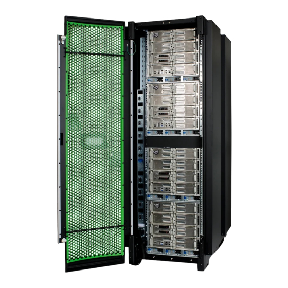
Page 58: Figure 3-1 Sgi Uv 3000 D-Rack System And Front Lock Example
3: System Overview Figure 3-1 SGI UV 3000 D-Rack System and Front Lock Example 007-6402-001... -
Page 59: System Models
DVD drive available to connect to the BaseIO blade. Figure 3-2 shows an example of how IRU placement is done in a single-rack SGI UV 3000 server. The system requires a minimum of one 42U tall rack with three single-phase power distribution unit (PDU) plugs per IRU installed in the rack. -
Page 60: Figure 3-2 Sgi Uv 3000 Iru And Rack Example
3: System Overview UV Rack Optional 1U administration node Optional 1U administration console Individual Rack Unit (IRU) Figure 3-2 SGI UV 3000 IRU and Rack Example 007-6402-001... -
Page 61: System Architecture
ASIC enables any processor in the SSI to access the memory of all processors in the SSI. Figure 3-3 on page 42 shows a functional block diagram of the SGI UV 3000 series system IRU. System configurations of up to eight IRUs can be constructed without the use of external routers. -
Page 62: Figure 3-3 Functional Block Diagram Of The Individual Rack Unit (Iru)
3: System Overview IRU Backplane Connections Left Right Backplane Backplane Note: this drawing only shows the cabling between the compute blades within the IRU. External cabling (cabling that exits the IRU) is not shown. Figure 3-3 Functional Block Diagram of the Individual Rack Unit (IRU) 007-6402-001... -
Page 63: System Features
System Features System Features The main features of the SGI UV 3000 series server systems are discussed in the following sections: • “Modularity and Scalability” on page 43 • “Distributed Shared Memory (DSM)” on page 43 • “Chassis Management Controller (CMC)” on page 45 •... -
Page 64: Figure 3-4 Sgi Uv 3000 Blade Nodes Block Diagram Example
3: System Overview • The total memory within the NUMAlinked system is referred to as global memory. Figure 3-4 SGI UV 3000 Blade Nodes Block Diagram Example 007-6402-001... -
Page 65: Distributed Shared I/O
Cache Coherency The SGI UV 3000 server series use caches to reduce memory latency. Although data exists in local or remote memory, copies of the data can exist in various processor caches throughout the system. Cache coherency keeps the cached copies consistent. -
Page 66: Non-Uniform Memory Access (Numa)
When a processor modifies a block of data, the processors that have the same block of data in their caches must be notified of the modification. The SGI UV 3000 server series uses an invalidation method to maintain cache coherence. The invalidation method purges all unmodified copies of the block of data, and the processor that wants to modify the block receives exclusive ownership of the block. - Page 67 System Features – All high speed links including Intel Quick Path Interconnect (QPI), Intel Scalable Memory Interconnect (SMI), and PCIe have CRC check and retry. – The NUMAlink interconnect network is protected by cyclic redundancy check (CRC). – Each blade/node installed has status LEDs that indicate the blade’s operational condition;...
-
Page 68: System Components
The SGI UV 3000 series system features the following major components: • 24U or 42U rack. These racks are used for both compute and I/O racks in the SGI UV 3000 system. Up to four IRUs can be installed in each 42U rack. There is also space for an RMC or optional administrative node and other optional 19-inch rackmounted components. -
Page 69: Figure 3-5 Sgi Uv 3000 Iru System Components Example
3 blade 7 Compute Compute blade 2 blade 6 Compute Compute blade 1 blade 5 SERIAL Compute Compute LAN0 LAN1 blade 0 blade 4 SSD1 SSD0 USB1 USB3 USB0 USB2 Figure 3-5 SGI UV 3000 IRU System Components Example 007-6402-001... -
Page 70: Optional Baseio Ssds
3: System Overview Optional BaseIO SSDs The BaseIO blade can be configured with one or two internal 1.8-inch solid state drives (SSDs). These drives are located in the lower-left section of the BaseIO blade, as seen in Figure 3-6. The SSDs can be configured as JBOD or RAID1. The RAID1 SSD pair is a software RAID1 and two SSDs must be ordered with the system BaseIO to enable this configuration. -
Page 71: Mic/Gpu Enabled Compute Blade
System Components MIC/GPU Enabled Compute Blade The single-socket MIC/GPU enabled compute blade has one single socket node blade and supports one PCIe accelerator card. The MIC/GPU enabled compute blade has the following features: • One HARP ASIC based board assembly with twelve NUMALink six (NL6) ports that connect the blade to the backplane and four NL6 ports connecting the blade to external QSFP ports. -
Page 72: Bay (Unit) Numbering
001. Optional System Components Availability of optional components for the SGI UV 3000 systems may vary based on new product introductions or end-of-life components. Some options are listed in this manual, others may be introduced after this document goes to production status. -
Page 73: Rack Information
“The 24U (Short) Rack” on page 59 Overview At the time this document was published only the tall (42U) SGI UV 3000 rack (shown in Figure 4-2) and the optional 24U (short rack) are available from the SGI factory for use with SGI UV systems. -
Page 74: Sgi Uv 3000 Series Rack (42U)
4: Rack Information SGI UV 3000 Series Rack (42U) The tall rack (shown in Figure 4-1 on page 55) has the following features and components: • Front and rear door. The front door is opened by grasping the outer end of the rectangular-shaped door piece and pulling outward. -
Page 75: Figure 4-1 Sgi Uv Air-Cooled D-Rack Example (Rear Lock Shown)
SGI UV 3000 Series Rack (42U) Each three-phase power distribution unit has 21 outlet connections. Figure 4-1 SGI UV Air-cooled D-Rack Example (Rear Lock Shown) 007-6402-001... -
Page 76: Figure 4-2 Front Lock On Tall (42U) Rack
4: Rack Information Figure 4-2 Front Lock on Tall (42U) Rack 007-6402-001... -
Page 77: Figure 4-3 Optional Water-Chilled Cooling Units On Rear Of Sgi 42U Rack
SGI UV 3000 Series Rack (42U) Figure 4-3 Optional Water-Chilled Cooling Units on Rear of SGI 42U Rack 007-6402-001... -
Page 78: Sgi Uv 3000 42U System Rack Technical Specifications
4: Rack Information SGI UV 3000 42U System Rack Technical Specifications Table 4-1 lists the technical specifications of the SGI UV 3000 series tall rack. Table 4-1 Tall Rack Technical Specifications Characteristic Specification Height 79.5 in. (201.9 cm) Width 31.3 in. (79.5 cm) Depth 45.8 in. -
Page 79: The 24U (Short) Rack
The 24U (Short) Rack The 24U (Short) Rack The 24U (short) SGI rack can hold system compute nodes, IRUs, an RMC, switches, and optional storage or console equipment. Figure 4-4 shows a front-view example of the optional 24U rack used with SGI systems. Note: The 24U rack uses single-phase power only. -
Page 80: Figure 4-5 Sgi 24U (Short) Rack Rear View Example
4: Rack Information Table 4-2 lists the technical specifications of the SGI 24U rack. Table 4-2 Short (24U) Rack Technical Specifications Characteristic Specification Height 50.25 in. (127.6 cm) [24U internal height] Width 24 in. (61 cm) Depth 42 in. (106.7 cm) Weight (full) 775 lbs (352.3 kg) approximate Shipping length/width/height... -
Page 81: Optional Octal Router Chassis Information
SGI sales or service representative. The standard routers used in the SGI UV 3000 systems are the NL6 router blades located internally to each IRU. Each of these first level routers contain a single 16-port NL6 HARP router ASIC. -
Page 82: Sgi Uv 3000 Series Numalink Octal Router Chassis
5: Optional Octal Router Chassis Information SGI UV 3000 Series NUMAlink Octal Router Chassis The NUMAlink 6 ORC router is a 7U-high fully self contained chassis that holds up to eight 16-port NL6 router blade assemblies. Figure 5-1 shows an example rear view of the ORC with no power or NUMAlink cables connected. -
Page 83: Figure 5-2 Sgi Uv 3000 Optional Orc Chassis Example (Front View)
SGI UV 3000 Series NUMAlink Octal Router Chassis Figure 5-2 SGI UV 3000 Optional ORC Chassis Example (Front View) Note: The NUMAlink unit’s CMC is connected to the CMC in each IRU installed in the rack. 007-6402-001... -
Page 84: Sgi Uv 3000 External Numalink System Technical Specifications
5: Optional Octal Router Chassis Information SGI UV 3000 External NUMAlink System Technical Specifications Table 5-1 lists the basic technical specifications of the SGI UV 3000 series external NUMAlink ORC chassis. Table 5-1 External NUMAlink Technical Specifications Characteristic Specification Height 7U or 12.25 in. -
Page 85: Add Or Replace Procedures
To avoid problems that could void your warranty, your SGI or other approved service provider should perform all the setup, addition, or replacement of parts, cabling, and service of your SGI UV 3000 system, with the exception of the following: •... -
Page 86: Preparing The System For Maintenance Or Upgrade
6: Add or Replace Procedures Preparing the System for Maintenance or Upgrade To prepare the system for maintenance, follow these steps: If you are logged on to the system, log out. Follow standard procedures for gracefully halting the operating system. 2. -
Page 87: Removing And Replacing An Iru Enclosure Power Supply
Removing and Replacing an IRU Enclosure Power Supply To remove and replace power supplies in an SGI UV 3000 IRU, you do not need any tools. Under most circumstances a single power supply in an IRU can be replaced without shutting down the enclosure or the complete system. -
Page 88: Figure 6-2 Replacing An Iru Enclosure Power Supply
6: Add or Replace Procedures 3. Press the retention latch of the power supply toward the power connector to release the supply from the enclosure, see Figure 6-1 on page 67. 4. Using the power supply handle, pull the power supply straight out until it is partly out of the chassis. -
Page 89: Replacing A System Fan (Blower)
Replacing a System Fan (Blower) Replacing a System Fan (Blower) Chassis cooling for each UV 3000 IRU is provided by nine, heavy duty, counter-rotating fans. Each fan unit is made up of two fans joined back-to-back, which rotate in opposite directions. The counter-rotating action increases airflow and dampens vibration levels. -
Page 90: Figure 3-6
CMC-1 not used CMC-0 Figure 6-3 UV 3000 Rear Fan Assembly (Blowers) Use the following steps and illustrations to replace an enclosure fan: Open the rack’s rear door and identify the fan that has failed, see Figure 6-4 on page 71. -
Page 91: Figure 6-4 Removing A Fan From The Rear Assembly
Replacing a System Fan (Blower) Figure 6-4 Removing a Fan From the Rear Assembly 3. Slide a new blower assembly completely into the open slot until the fan-interconnect engages and the new unit is flush with the rear of the assembly, see Figure 6-5 on page 72. 4. -
Page 92: Replacing A Blade-Mounted Drive
6: Add or Replace Procedures Figure 6-5 Replacing an Enclosure Fan Replacing a Blade-Mounted Drive The dual-disk drive blade is used to house two disk drives as shown in Figure 6-6 on page 73. This section describes how to install or remove the drives. The blade supports RAID 1, RAID 0 and JBOD disk drives. -
Page 93: Figure 6-6 Removing The Uv 3000 System Disk Example
Figure 6-6 Removing the UV 3000 System Disk Example Installation of a disk drive into the riser blade is the opposite of extraction, use the following steps: Install a drive (pre-mounted on sled) into the dual-disk drive riser blade with the drive assembly oriented as shown in Figure 6-7 on page 74. -
Page 94: Figure 6-7 Replacing A Uv 3000 Blade-Mounted Disk Example
6: Add or Replace Procedures Push to engage Push to install Figure 6-7 Replacing a UV 3000 Blade-Mounted Disk Example 007-6402-001... -
Page 95: Troubleshooting And Diagnostics
Chapter 7 Troubleshooting and Diagnostics This chapter provides the following sections to help you troubleshoot your system: • “Troubleshooting Chart” on page 76 • “LED Status Indicators” on page 77 • “SGI Electronic Support” on page 79 007-6402-001... -
Page 96: Troubleshooting Chart
7: Troubleshooting and Diagnostics Troubleshooting Chart Table 7-1 lists recommended actions for problems that can occur. To solve problems that are not listed in this table, use the SGI Electronic Support system or contact your SGI system support representative. For more information about the SGI Electronic Support system, see the “Optional SGI Remote Services (SGI RS)”... -
Page 97: Led Status Indicators
LED Status Indicators LED Status Indicators There are a number of LEDs on the front of the IRUs that can help you detect, identify and potentially correct functional interruptions in the system. The following subsections describe these LEDs and ways to use them to understand potential problem areas. IRU Power Supply LEDs Each power supply installed in an IRU has a bi-color status LED. -
Page 98: Compute/Memory Blade Leds
7: Troubleshooting and Diagnostics Compute/Memory Blade LEDs Each compute/memory blade installed in an IRU has a total of seven LED indicators visable behind the perforated sheetmetal of the blade. At the bottom end (or left side) of the blade (from left to right): •... -
Page 99: Sgi Electronic Support
SGI Electronic Support SGI Electronic Support The following services are part of the available integrated SGI Electronic Support system: SGI Remote Services (SGI RS) The optional SGI RS system automatically detects system conditions that indicate potential future problems and then notifies the appropriate personnel. This enables you and SGI global support teams to pro-actively support systems and resolve issues before they develop into actual failures. -
Page 101: Technical Specifications And Pinouts
“I/O Port Specifications” on page 85 System-level Specifications Table A-1 summarizes the SGI UV 3000 system configuration ranges. Note that while each dual-node compute/memory blade holds two processor sockets (one per node board); each processor socket can support multiple “cores”. -
Page 102: Physical Specifications
A: Technical Specifications and Pinouts Physical Specifications Table A-2 shows the physical specifications of the SGI UV 3000 system. Table A-2 SGI UV 3000 Physical Specifications Feature Specification Dimensions for a single 24-inch Height: 79.5 in. (201.9 cm) wide tall rack, including doors and Width: 31.3 in. -
Page 103: Environmental Specifications
Relative humidity 10% to 80% operating (no condensation) 8% to 95% non-operating (no condensation) Heat dissipation full SGI UV 3000 (rack) 115.6 kBTU/hr maximum (based on 33.88 kW) approximate Cooling requirement Ambient air or optional water cooling Air flow: intake (front),... -
Page 104: Power Specifications
A: Technical Specifications and Pinouts Power Specifications Table A-4 shows the power specifications for the system. Table A-4 Power Specifications Feature Specification Single-phase power requirements Voltage 200-240V (180-254 VAC min/max) Frequency 50-60 Hz Power 33.88 kW per rack Hold-up time 16 ms Three-phase power requirements Voltage... -
Page 105: I/O Port Specifications
A single USB keyboard/mouse is supported by the baseIO blade connectors The BaseIO VGA interface (see Table A-5 on page 86) can be used for all basic interaction with your SGI UV 3000 system. Note that it does not provide a direct interconnect to the system CMC. Figure A-1... -
Page 106: Table A-5 Vga Pin Functions
A: Technical Specifications and Pinouts Table A-5 VGA Pin Functions Pin Number Function Green Blue Ground Ground Ground Ground Ground Ground DDCDAT HSYNC VSYNC DDCCLK 007-6402-001... -
Page 107: Ethernet Port
I/O Port Specifications Ethernet Port The system auto-selects the Ethernet port speed and type (duplex vs. half-duplex) when the server is booted, based on what it is connected to. Figure A-2 shows the Ethernet port. Pin 4 Pin 5 Pin 6 Pin 3 Pin 7 Pin 2... -
Page 108: Serial Ports
A: Technical Specifications and Pinouts Serial Ports The service nodes and the optional router modules have 9-pin serial interface connectors. These ports are for console interface and are capable of transferring data at rates as high as 230 kbps. Other features of the ports include the following: •... -
Page 109: Table A-7 Serial Port Pinout
I/O Port Specifications Table A-7 shows pinout assignments for the 9-pin male DB-9 connector. Table A-7 Serial Port Pinout Assignment Description Data carrier detect Receive data Transmit data Data terminal ready Signal ground Data set ready Request to send Clear to send Ring indicator 007-6402-001... -
Page 110: Usb Type A Connector
A: Technical Specifications and Pinouts USB Type A Connector Figure A-4 shows the USB type A connector provided on the baseIO riser blade that supports general USB applications and optional keyboard and mouse configurations. Table A-8 lists the pin assignments for the USB type A connector. Figure A-4 Pin Number Locations for USB Type A Connector Table A-8... -
Page 111: Safety Information And Regulatory Specifications
Appendix B Safety Information and Regulatory Specifications This appendix provides safety information and regulatory specifications for your system in the following sections: • “Safety Information” on page 91 • “Regulatory Specifications” on page 93 Safety Information Read and follow these instructions carefully: Follow all warnings and instructions marked on the product and noted in the documentation included with this product. - Page 112 B: Safety Information and Regulatory Specifications 9. Do not attempt to service this product yourself except as noted in this guide. Opening or removing covers of node and switch internal components may expose you to dangerous voltage points or other risks. Refer all servicing to qualified service personnel. 10.
-
Page 113: Regulatory Specifications
Regulatory Specifications Regulatory Specifications The following topics are covered in this section: • “CMN Number” on page 93 • “CE Notice and Manufacturer’s Declaration of Conformity” on page 93 • “Electromagnetic Emissions” on page 94 • “Shielded Cables” on page 96 •... -
Page 114: Electromagnetic Emissions
B: Safety Information and Regulatory Specifications Electromagnetic Emissions This section provides the contents of electromagnetic emissions notices from various countries. FCC Notice (USA Only) This equipment complies with Part 15 of the FCC Rules. Operation is subject to the following two conditions: •... -
Page 115: Industry Canada Notice (Canada Only)
Regulatory Specifications Industry Canada Notice (Canada Only) This Class A digital apparatus meets all requirements of the Canadian Interference-Causing Equipment Regulations. Cet appareil numérique német pas de perturbations radioélectriques dépassant les normes applicables aux appareils numériques de Classe A préscrites dans le Règlement sur les interferences radioélectriques établi par le Ministère des Communications du Canada. -
Page 116: Shielded Cables
B: Safety Information and Regulatory Specifications Shielded Cables This SGI system is FCC-compliant under test conditions that include the use of shielded cables between the system and its peripherals. Your system and any peripherals you purchase from SGI have shielded cables. Shielded cables reduce the possibility of interference with radio, television, and other devices. -
Page 117: Laser Compliance Statements
Regulatory Specifications Laser Compliance Statements The DVD-ROM drive in this computer is a Class 1 laser product. The DVD-ROM drive’s classification label is located on the drive. Warning: Avoid exposure to the invisible laser radiation beam when the device is open. Warning: Attention: Radiation du faisceau laser invisible en cas d’ouverture. -
Page 118: Lithium Battery Statement
B: Safety Information and Regulatory Specifications Lithium Battery Statement Warning: There is danger of explosion if a lithium battery is incorrectly replaced in this product. Replace a battery only with the same or equivalent type recommended by the manufacturer. Dispose of used batteries according to the manufacturer’s instructions. 007-6402-001...
Need help?
Do you have a question about the UV 3000 and is the answer not in the manual?
Questions and answers