
Subscribe to Our Youtube Channel
Related Manuals for Javad Maxor


Summary of Contents for Javad Maxor
- Page 1 Maxor GNSS Receiver User’s Manual © Copyright Javad Navigation Systems, Inc. March, 2004...
-
Page 3: Table Of Contents
Receiver Overview........1-5 Maxor Accessory Kit ........1-6 Cables . - Page 4 Power Management ....... 2-4 Charging the Maxor ........2-7 Connecting the Maxor and a Computer .
- Page 5 Chapter 3: Setup and Survey ....3-1 Maxor Receiver Setup ....... . . 3-2 External Antenna Setup .
- Page 6 Specifications........B-1 Maxor Specifications ......B-1 Connector Specifications .
- Page 7 Warranty Terms ........E-1 Index www.javad.com Maxor User’s Manual V...
- Page 8 Notes: VI Maxor User’s Manual www.javad.com...
- Page 9 Maxor Radome........1-11...
- Page 10 Maxor MinPad ........
- Page 11 Maxor MinPad ........
- Page 12 USB Connector ........B-11 X Maxor User’s Manual...
- Page 13 Chapter 5: Troubleshooting ..... 5-1 Technical Support E-mail ......5-10 www.javad.com Maxor User’s Manual XI...
- Page 14 USB Connector Specifications ......B-11 External Antenna Connector Specifications ....B-12 XII Maxor User’s Manual www.javad.com...
-
Page 15: Preface
Manual (the "Manual") have been prepared by Javad Navigation Systems, Inc. ("JNS") for owners of Javad products. It is designed to assist owners with the use of the Maxor and its use is subject to these terms and conditions (the "Terms and Conditions"). - Page 16 Manual without JNS' express written consent and may only use such information for the care and operation of your Maxor. The information and data in this Manual are a valuable asset of JNS and are developed by the expenditure of considerable work, time and money, and are the result of original selection, coordination and arrangement by JNS.
- Page 17 Conditions (including the Software license, warranty and limitation of liability). SAFETY – Improper use of the Maxor can lead to injury to persons or property and/or malfunction of the product. The Maxor should only be repaired by authorized JNS warranty service centers. Users should review and heed the safety warnings in “Safety Warnings”.
-
Page 18: Regulatory Information
• Move the equipment away from the receiver. • Plug the equipment into an outlet on a circuit different from that to which the receiver is powered. • Consult the dealer or an experienced radio/television technician for additional suggestions. XVI Maxor User’s Manual www.javad.com... -
Page 19: Canadian Emissions Labeling Requirements
WARNING: Notification that an action will result in system damage, loss of data, loss of warranty, or personal injury. ANGER NDER NO CIRCUMSTANCES SHOULD THIS ACTION BE PERFORMED www.javad.com Maxor User’s Manual XVII... - Page 20 Notes: XVIII Maxor User’s Manual www.javad.com...
-
Page 21: Chapter 1: Introduction
Receiver Overview ..... page 1-5 Maxor Accessory Kit....page 1-6 Literature . -
Page 22: Overview
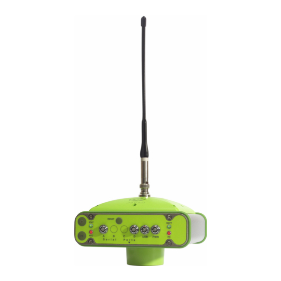
(Figure 1-1). Figure 1-1. Maxor Receiver The Maxor can receive and process both L1 and L2 signals, improving the accuracy of your survey points and positions. The GNSS component of Maxor receivers means you can access both the GPS (Global Positioning System) -
Page 23: Principles Of Operation
(satellite positions as a function of time), to ensure the satellites transmit data properly. • User – The community and military that use GPS/GLONASS receivers and the corresponding satellites to calculate positions. www.javad.com Maxor User’s Manual 1-3... -
Page 24: Calculating Positions
Several factors combine to provide fault tolerance, including: –Receiver Autonomous Integrity Monitoring (RAIM) detects faulty GPS and GLONASS satellites and removes them from the position calculation. –Wide Area Augmentation System (WAAS) creates and transmits DGPS correction messages. 1-4 Maxor User’s Manual www.javad.com... -
Page 25: Conclusion
Earth. This overview simply outlines the basics of GPS and GLONASS positioning. For more detailed information, visit the JNS website (www.javad.com). Receiver Overview When power is turned on and the receiver self-test completes, the receiver’s 20 channels initialize and begin tracking visible GNSS satellites. -
Page 26: Maxor Accessory Kit
• Static or dynamic modes Maxor Accessory Kit Although the Maxor can be supplied with a number of different accessories, this manual refers to the standard kit. For more information about different accessories available, please contact your local Javad dealer or visit the accessories section of the JNS website: (http://www.javad.com/cgi-bin/WebShop/cgi?Action=DrawAccessoriesList). -
Page 27: Software
(www.javad.com). The following software will also be useful for operating, caring for and using your Maxor receiver, and may be required for some applications. • FLoader – Javad's firmware loader; available on the JNS website. • PDLCONF from Pacific Crest – firmware upgrades available from the Pacific Crest website (www.paccrst.com/download/upgrade.htm). -
Page 28: Getting To Know Your Maxor
Getting to Know Your Maxor Getting to Know Your Maxor The Maxor is 159 mm wide, 159 mm deep, 115 mm high, weighs ~ 1.65 kg, and is versatile receiver and can be configured in several different ways, depending on the usage and function of the receiver at the jobsite. The casing allocates space for two nonremovable, on-board Li-Ion batteries and two Euro cards. -
Page 29: Power Board
I N T R O D U C T I O N Getting to Know Your Maxor Your Maxor may be equipped with one of the following communication boards (however, your receiver may also be configured without a radio/modem): • UHF modem – a Pacific Crest PDL (Positioning Data Link) modem; either a 450- 470 MHz or 430-450 MHz;... -
Page 30: Gnss Receiver Board
GNSS receiver should run at least 17 hours for the Maxor-GD/GG or 14 hours the Maxor-GGD. The Li-Ion batteries used in the Maxor should run at no less than 98% capacity after 500 charging cycles. These batteries do not need to be drained before recharging. -
Page 31: External Components
I N T R O D U C T I O N Getting to Know Your Maxor External Components The Maxor casing includes panels for antenna attachment, a user interface, a power port, and ports for configuration. Radome Figure 1-2 shows the radome components. -
Page 32: Bottom Panel
• Antenna Reference Point (ARP) • The GPS/GLONASS external antenna connector (standard configuration) Figure 1-3. Maxor Bottom Panel Front Panel Figure 1-4 shows the Maxor’s front panel components. Figure 1-4. Maxor Front Panel (with and without USB) 1-12 Maxor User’s Manual www.javad.com... -
Page 33: Back Panel
• Vent plug – Equalizes the pressure between the inside of the receiver and the outside environment. • USB – Only available on the Maxor GGD with the Euro-112 card. Used for high- speed data transfer and communication between the receiver and an external device. -
Page 34: Option Authorization File (Oaf)
JNS dealer. • Type of signal (standard L1; optional L2) • Memory (standard 0 MB; for Maxor-GD/GG, optional up to 512 MB for Maxor-GGD, optional up to 1 GB) • Update rate standard 1Hz (optional 5, 10, or 20 Hz) •... -
Page 35: Chapter 2: Configuration
Powering the Maxor ....page 2-2 Charging the Maxor..... page 2-7 Connecting the Maxor and a Computer. -
Page 36: Powering The Maxor
The appropriate external power source must provide + 6 to +28 V DC and must be able to supply sufficient current (2.5 Amp) to operate/charge the receiver. 2-2 Maxor User’s Manual www.javad.com... -
Page 37: Battery Charger
• Press and hold the Reset key for about one second to ensure that the receiver is in Normal mode for accepting power. • Turn on the receiver by pressing and holding the green power key for about 0.5 seconds. www.javad.com Maxor User’s Manual 2-3... -
Page 38: Power Management
Power Management Use Javad's PCView software to manage the receiver's power. The complete description of PCView exceeds the scope of this manual, but can be found in the 2-4 Maxor User’s Manual... - Page 39 JNS website. To access the tab controlling the power settings of your receiver, take the following steps: Connect your receiver and computer. See “Connecting the Maxor and a Computer” on page 2-8 for this procedure. Once connected, click Configuration->Receiver.
-
Page 40: Select Power Output Modes - Ports
On Board – displays the voltage drawn by the receiver board. • Battery A – displays the voltage of battery A. • Battery B – displays the voltage of battery B. • Charger – displays the charger’s output voltage during battery charging. • 2-6 Maxor User’s Manual www.javad.com... -
Page 41: Charging The Maxor
• Leave overnight. Fully charging the batteries takes approximately seven hours. The internal batteries cannot be overcharged. Tip: To check the status of the internal batteries, view the BATT LED on the receiver front panel. www.javad.com Maxor User’s Manual 2-7... -
Page 42: Connecting The Maxor And A Computer
To configure, manage files, or maintain the Maxor, you need to connect the receiver and a computer using an RS232 cable, and start PCView. Also, if an USB port is available on your Maxor, you can use an USB cable and a computer with the JNS USB driver for such connection. -
Page 43: Establishing An Rs-232 Cable Connection
Continue with Step 1 in “Establishing a PCView Connection” on page 2-10. Establishing a USB Cable Connection Make sure the computer has Javad’s USB driver installed (available from http:// javad.com/jns/downloads/freesoft/jns_usb.zip) before continuing. Using the USB cable, connect the USB port on the receiver to a USB port on the computer. -
Page 44: Establishing A Pcview Connection
C O N F I G U R A T I O N Connecting the Maxor and a Computer Continue with Step 1 in “Establishing a PCView Connection” on page 2-10. Establishing a PCView Connection PCView is a personal computer software used to manage the various functions of your receiver. - Page 45 C O N F I G U R A T I O N Connecting the Maxor and a Computer –For Bluetooth connections, disable RTS/CTS handshaking. For RS-232 connections enable RTS/CTS handshaking. Figure 2-10. Bluetooth and RS-232 Connection Parameters For USB connections (Figure 2-11) •...
-
Page 46: Maxor Configuration
Maxor Configuration PCView is Javad's receiver configuration software, used to configure the various parts of the Maxor receiver. Any settings made using PCView will be saved in the receiver's memory, and will be reflected when you use the MinPad. The full range of PCView configuration and function is outside the scope of this manual. -
Page 47: Receiver Configuration
Figure 2-15. Receiver Configuration – MinPad Tab If your jobsite is in an area that has obstructions (buildings, trees, etc.), and/or the antenna location is near reflective objects, configure the receiver to reduce errors from these sources. www.javad.com Maxor User’s Manual 2-13... -
Page 48: Advanced Configuration - Multipath Reduction
Enable Common Tracking • Static Mode (used for static receivers only, disable if using the receiver as • a Rover) Figure 2-17. Advanced Configuration – Loop Management Click OK to close the Receiver Configuration screen. 2-14 Maxor User’s Manual www.javad.com... -
Page 49: Minpad Configuration
PCView or clearing the NVRAM. MinPad Configuration The Maxor's minimum interface (MinPad) consists of three keys (Power, FN, and Reset) and up to four LEDs (STAT, REC, BATT, and RX) that control and display the receiver's operation (Figure 2-18). -
Page 50: Connection Parameters - Rts/Cts Handshaking
You use PCView to configure MinPad settings. Refer to the PCView User's Manual for all possible MinPad configurations. Connect your receiver and computer. See “Connecting the Maxor and a Computer” for this procedure. On the Connection Parameters dialog box, enable RTS/CTS handshaking (Figure 2-19) and then click Connect. -
Page 51: Receiver Configuration - Minpad Tab
File Name Prefix parameter This parameter specifies what prefix will be added to the names of the receiver files created when pressing FN. The prefix can be up to 20 characters long. The default value is log. www.javad.com Maxor User’s Manual 2-17... - Page 52 Values are 0 to 86400 seconds. The default value is zero seconds. • Files (total) - a counter that specifies how many multiple log files must be • created in AFRM until this mode automatically turns off. This counter 2-18 Maxor User’s Manual www.javad.com...
- Page 53 MinPad User's Manual and PCView User's Manual. Initial Data Collection Dynamic Mode parameter These radio buttons specify the starting occupation type descriptor inserted at the beginning of receiver files logged. You select Static or Kinematic to www.javad.com Maxor User’s Manual 2-19...
- Page 54 (to a newly created or an existing file) in the following three cases: After pressing the Power key to turn on the receiver. • After resetting the receiver (with PCView or the Reset key). • 2-20 Maxor User’s Manual www.javad.com...
-
Page 55: Radio Configuration
To access your PDL UHF radio modem, you create a daisy chain between the Maxor serial port (A or D) and the radio modem (Port C) using PCView. You then activate the PDL configuration program on your PC and proceed with the radio configuration. -
Page 56: Manual Mode - Command Responses
C O N F I G U R A T I O N Radio Configuration To create a daisy chain between the receiver's port (A or D) and the Maxor PDL modem, type each of the following commands, pressing Enter (or clicking Send command) after each command. -
Page 57: Select Serial Port
Click the Pacific Crest logo in the upper left corner of the main screen (Figure 2-25). Figure 2-25. PDL Top Left Corner Icon Menu From the pop-up menu, choose Select Serial Port (Figure 2-26). Figure 2-26. Select Serial Port www.javad.com Maxor User’s Manual 2-23... -
Page 58: Select Serial Port And Click Ok
This process can take a few minutes. From the same pop-up menu, click Set Capture Method->Soft Break (Figure 2-28). Figure 2-28. Set Capture Method->Soft Break Click Load to connect to the radio (Figure 2-29). Figure 2-29. Click Load 2-24 Maxor User’s Manual www.javad.com... - Page 59 GMSK 4-Level-FSK Digisquelch High High Forward Error Correction disable enable Scrambling enable enable Local Address Channel Select: –Manual enable enable –Channel TX RX set channel and frequency as set channel and frequency as desired desired www.javad.com Maxor User’s Manual 2-25...
- Page 60 Radio Configuration Figure 2-31. PDL Radio Link Tab Notice: The Base and internal Maxor (Rover) PDL radios must be configured with the same Channels, Radio Link characteristics (except Digisquelch) and Serial Interface parameters. Typically, Digisquelch is set on High for Rover and Low for Base station.
- Page 61 Figure 2-32. PDL Serial Interface Tab If you made changes, click the Program button on the left of the screen to save them to the modem's memory (Figure 2-33). Figure 2-33. PDL – Click Program www.javad.com Maxor User’s Manual 2-27...
-
Page 62: Connection Parameters - Manual Mode Only
Figure 2-35. Connection Parameters – Manual Mode Only On the Manual Mode screen, write the following commands, pressing Enter (or clicking Send command) after each command. When finished, you should have five responses (Figure 2-36). QUIT %%set,cur/term/imode,cmd %%set,dev/ser/c/echo,/dev/null %%set,dev/ser/c/imode,cmd 2-28 Maxor User’s Manual www.javad.com... -
Page 63: Configuring A Gsm Radio Modem
Connect your receiver and computer using an RS232 cable and appropriate serial ports. Also, if your Maxor receiver has a USB port, you can use a USB cable and a computer with the JNS USB driver installed (this driver is available to download from http://www.javad.com/). -
Page 64: File->Manual Mode
Enter the 'wait on data from modem' timeout: %% set,/par/modem/c/ rcvtimeout,5 Command 5. • Enter the service word repeat period: %% set,/par/modem/c/ sndtime,2 Command 6. • Set the required modem mode: %% set,/par/modem/c/ mode,master – for the receiver configured as a rover, 2-30 Maxor User’s Manual www.javad.com... -
Page 65: How To Configure A Gsm Radio Modem With Fieldview2-31
Once you have BTCONF available, follow these steps to configure the Bluetooth module. Using the RS232 cable, connect the serial port of your computer to the receiver’s serial port A. Press the power buttons on the receiver and computer to turn them on. www.javad.com Maxor User’s Manual 2-31... -
Page 66: Bluetooth Module Configuration Main Screen
(Figure 2-40) displays the following information: Bluetooth name – the name of the Bluetooth module, set in the Parameters • tab. Bluetooth address – the unique electronic address for your Bluetooth • module. Firmware base. • 2-32 Maxor User’s Manual www.javad.com... - Page 67 Authentication – enable to require a PIN before two Bluetooth enabled • devices (such as, the receiver and a computer) can establish a communication link. The two devices must use the same PIN. www.javad.com Maxor User’s Manual 2-33...
-
Page 68: Collecting Almanacs
The receiver regularly updates the almanac and stores the most recent almanac in its Non-Volatile Random Access Memory (NVRAM). Set up the receiver (connect the external antenna if needed) in a location with a clear view of the sky. 2-34 Maxor User’s Manual www.javad.com... - Page 69 • After loading a new OAF. • After loading new firmware. • After clearing the NVRAM. • Before surveying. The collection and/or update of an almanac can take as long as 15 minutes. www.javad.com Maxor User’s Manual 2-35...
- Page 70 Notes: 2-36 Maxor User’s Manual www.javad.com...
-
Page 71: Chapter 3: Setup And Survey
This chapter describes the following: Maxor Receiver Setup ....page 3-2 Surveying with the Maxor ....page 3-7 Chapter Tip: To set up your Maxor receiver, you must: Configure the receiver as described in “Configuration”. -
Page 72: Maxor Receiver Setup
Set up Receiver This section assumes you have already configured your receiver using PCView. Place the Maxor on the appropriate tripod or bipod. Center the receiver over the point at which data will be collected. For most applications, this should be at a location with a clear view of the sky. - Page 73 Figure 3-1 illustrates the antenna offsets. (See Figure 1-3 on page 1-12 and Figure 1-4 on page 1-12 for the exact SHMM location.) 79.5mm Figure 3-1. Maxor GD and Maxor GGD Antenna Offsets SHMM to ARP vertical offset = 30.5 mm •...
-
Page 74: External Antenna Setup
Press and hold the power key until all lights go out, then release. External Antenna Setup The Maxor can also be used with an external antenna. Follow the steps below to connect an external antenna to the Maxor and measure its offset. -
Page 75: Marant+ Antenna Offset Measurements
0.294 ft Record the antenna height, point name, and start time in the field notes. Attach the flexible RF cable from the external antenna to the antenna connector on the bottom panel of the Maxor. www.javad.com Maxor User’s Manual 3-5... -
Page 76: Configuration->Receiver
Maxor Receiver Setup Turn on the Maxor and continue with step 3 on page 3-3. The Maxor antenna default is set to Auto, allowing the receiver to detect automatically the available antenna (whether internal or external). If you have changed this setting, or the receiver does not detect the external antenna, use the procedure below to set the External Antenna detection option. -
Page 77: Surveying With The Maxor
S E T U P A N D S U R V E Y Surveying with the Maxor Surveying with the Maxor The Maxor receiver can be used to perform the following types of surveying: • Static • Kinematic • Real-time kinematic (RTK) -
Page 78: Configuration->Receiver->Minpad
The procedure that follows describes the steps the operator should take to perform a Static Survey using MinPad. Connect your receiver and computer. See “Connecting the Maxor and a Computer” on page 2-8 for this procedure. Open PCView, click Configuration->Receiver->MinPad and specify the following parameters, then click Apply (Figure 3-5): Recording Interval –... -
Page 79: Advanced->Multipath
Enable Common Tracking – enable • Static mode – enable (disable for Rover receivers) • Figure 3-7. Advanced->loop Management Set up each antenna and receiver as described in “Maxor Receiver Setup” on page 3-2. Begin your survey. www.javad.com Maxor User’s Manual 3-9... -
Page 80: Kinematic Survey
S E T U P A N D S U R V E Y Surveying with the Maxor Kinematic Survey You can use the kinematic survey method in two ways: • Stop and go survey • Kinematic continuous (trajectory) survey... -
Page 81: Kinematic Continuous
S E T U P A N D S U R V E Y Surveying with the Maxor 4. Check the STAT light for satellites tracked. 5. When finished, press the FN key for less than a second to assign the Rover to kinematic. -
Page 82: Real-Time Kinematic Survey
Setting up an RTK Base Station To configure an RTK Base station using PCView, take the following steps: 1. Set up the Base station receiver's antenna as described in “Maxor Receiver Setup” on page 3-2. 2. Connect an external modem to port C for the Lexon-GGD receiver or port D for the Maxor receiver. -
Page 83: Receiver Configuration - Positioning
S E T U P A N D S U R V E Y Surveying with the Maxor 7. Click the Set all parameters to defaults button located at the bottom of the Receiver Configuration screen (Figure 3-9). Figure 3-9. Set All Parameters to Defaults 8. - Page 84 S E T U P A N D S U R V E Y Surveying with the Maxor –Enable Averaged and enter the Averaged Span in seconds, then click Apply. Click Tools->Reset receiver and wait until the specified interval (span) completes.
-
Page 85: Setting Up An Rtk Rover
Use the following steps to set up an RTK Rover station. You should already have programmed the modem. 1. Set up the Rover station receiver's antenna as described in “Maxor Receiver Setup” on page 3-2. 2. Connect your receiver and computer. See “Connecting the Maxor and a Computer”... - Page 86 S E T U P A N D S U R V E Y Surveying with the Maxor 3. Click Configuration->Receiver. 4. Select the Positioning tab and set the Position Masks, Elevation mask (degrees) parameter to 15 (Figure 3-10 on page 3-13).
- Page 87 S E T U P A N D S U R V E Y Surveying with the Maxor • Baud rate drop-down list – select a baud rate (i.e., the receiver port baud rate at which differential messages will be received from modem).
- Page 88 S E T U P A N D S U R V E Y Surveying with the Maxor • Total number of received corrupt messages If the receiver is not (for some reason) receiving differential corrections, or if none of the ports has been configured to receive differential corrections, the LQ field will either be empty or it will look like this: 100%(999,0000,0000).
-
Page 89: Chapter 4: Operation
PERATION This chapter describes the following standard Maxor operating procedures: Using the MinPad ..... . page 4-2 Downloading Files to a Computer..page 4-7 Deleting Files. -
Page 90: Using Minpad
O P E R A T I O N Using MinPad Using MinPad The MinPad is Javad's minimum interface used to display and control data input and output (Figure 4-1). Figure 4-1. Maxor MinPad Power Key Pressing the power key turns the receiver on and off. -
Page 91: Fn Key And Record Led
• After loading new firmware or clearing the receiver's NVRAM, the receiver checks its internal file system. During this operation, the REC LED flashes orange, and the file system is not accessible for CDU (control display unit) applications or for data recording. www.javad.com Maxor User’s Manual 4-3... - Page 92 Green Release to start recording (Kinematic or Static post-processing occupation mode). Pressed for 5–8 Release to turn serial port A baud rate seconds to 9600 bps. Pressed for > 8 No light No function. seconds 4-4 Maxor User’s Manual www.javad.com...
-
Page 93: Battery Led
The color of the BATT LED indicates the level of internal battery charge in the Maxor: • Green – indicates greater than 90% charge. • Orange – indicates an intermediate charge. • Red – indicates less than 10% charge. www.javad.com Maxor User’s Manual 4-5... -
Page 94: Modem Led
• Blinking once a second – the batteries are being charged. • Blinking once every five seconds – the Maxor uses the internal batteries for power. • Not blinking – the receiver is in Zero Power Mode or the internal batteries are completely discharged and no external power is connected. -
Page 95: Downloading Files To A Computer
3. To switch back to normal, press the FN key. Downloading Files to a Computer When your survey finishes, you can download your survey files to a computer for storage, post-processing, or backup. Also, the Maxor memory holds a finite www.javad.com Maxor User’s Manual 4-7... - Page 96 PCView provides a File Manager to download files to your computer and delete files from the Maxor. Connect your receiver and computer. See “Connecting the Maxor and a Computer” on page 2-8 for this procedure. On the Connection Parameters dialog box, enable RTS/CTS handshaking (Figure 4-2).
-
Page 97: Download Files
Click the Download button. During the download, status indicators display next to each file (Figure 4-6 on page 4-10). Blue indicator – file in queue for downloading. • Red indicator – file currently downloading. • www.javad.com Maxor User’s Manual 4-9... -
Page 98: Deleting Files
PCView. Deleting Files Use the following steps to delete files from your receiver. Connect your receiver and computer. See “Connecting the Maxor and a Computer” on page 2-8 for this procedure. On the Connection Parameters dialog box, enable RTS/CTS handshaking (See Figure 4-2 on page 4-8.) -
Page 99: Checking An Oaf
RS232 cable, a computer, and PCView. Refer to the PCView User's Manual for a more complete description of the PCView software. Connect your receiver and computer. See “Connecting the Maxor and a Computer” on page 2-8 for this procedure. -
Page 100: Option Manager
• yes or no – the option is either enabled or disabled. Figure 4-9. Option Manager When finished, click Exit on the Option Manager screen, then click File- >Disconnect to prevent conflicts with serial port management. 4-12 Maxor User’s Manual www.javad.com... -
Page 101: Loading Oafs
>Disconnect to prevent conflicts with serial port management. Managing Receiver Memory When using the Maxor in static or dynamic applications, you may need to know the amount of memory the receiver's log file occupies. The specific memory size depends on the type of data being recorded. Use the formulas below to compute the approximate size of the receiver's log files. -
Page 102: Clearing The Nvram
(around 15 minutes). Clearing the NVRAM of your receiver will not delete any files already recorded in your Maxor's memory. However, it will reset your receiver settings to factory default values. In addition, the NVRAM keeps information about the receiver file system. Note... -
Page 103: Using Pcview To Clear Nvram
STAT LED flashes red. Figure 4-11. Tools->Clear NVRAM The receiver will automatically disconnect once the NVRAM is cleared. Changing Receiver Modes The Maxor receiver has four modes, two information modes and two power modes: • Normal Mode • Extended Information Mode •... -
Page 104: Zero Power Mode
Zero Power Mode When your Maxor is off, even in Sleep Mode, the power board will continue to draw power from the batteries. This means that if you fully charge your receiver, turn it off and store it, the receiver will drain its battery power in less than two months. -
Page 105: Loading New Firmware
Firmware is released as a compressed file that you download and decompress. This file contains the following three files: • ramimage.ldr - the Receiver board RAM file • main.ldp - the Receiver board Flash file • powbrd.ldr - the Power board RAM file www.javad.com Maxor User’s Manual 4-17... -
Page 106: Set Device Type
You must load all three files when loading new firmware. These files must come from the same firmware package. The Maxor uses FLoader, a Windows®-based utility, to load firmware onto the receiver and power boards. You can download FLoader to your computer from the JNS website. -
Page 107: Program Tab Settings
Reselect the correct file. Select the Device tab and set the Device Type as Receiver's Power Board (Figure 4-17). Figure 4-17. Set Device Type Click Get from Device for device information (Figure 4-17). www.javad.com Maxor User’s Manual 4-19... -
Page 108: Program Tab Settings
Reselect the correct file. Click File->Exit. Clear the receiver’s NVRAM (see“Clearing the NVRAM” on page 4-14) and update the almanac (“Collecting Almanacs” on page 2-34) after loading new firmware. 4-20 Maxor User’s Manual www.javad.com... -
Page 109: Chapter 5: Troubleshooting
ROUBLESHOOTING In general, as long as you follow the maintenance and safety instructions provided in this manual, you should have few problems with your Maxor. This chapter will help you diagnose and solve some common, minor problems you may encounter with your Maxor receiver. -
Page 110: Things To Check First
Power Problems All Maxor receivers are preset in the factory as "Auto Mode" for both the power and charger. If you want to check these settings, Connect your receiver and computer and run PCView (see “Connecting the Maxor and a Computer”... -
Page 111: Receiver Problems
The receiver may have If after charging your internal batteries overnight, and your a defective charger or Maxor is not powering, contact JNS Customer Support for defective internal advice. batteries. Receiver Problems The following are some of the most commonly encountered receiver problems. - Page 112 • Contact your Dealer to replace the cable. Connect your receiver and a computer using a free port The receiver port used for connection is not in (see “Connecting the Maxor and a Computer” on Command mode. page 2-8) and start PCView. Click Configuration->Receiver->Ports.
- Page 113 The receiver is not the proper configuration. See “Surveying with the configured as a Base Maxor” on page 3-7 for further information. or Rover. • If the receiver should function as a Rover, ensure it has the proper configuration. See “Surveying with the Maxor”...
- Page 114 Connect your receiver and a computer and start used at the Base and PCView. See “Connecting the Maxor and a Computer” Rover receivers. on page 2-8. Click Configuration->Receiver->Ports and set the same input/output format for both receivers.
-
Page 115: Bluetooth Problems
Connect your receiver and a computer using a free port The receiver port used for connection is not in (see“Connecting the Maxor and a Computer” on Command mode. page 2-8) and start PCView. Click Configuration->Receiver->Ports. Change the Input for the serial port used for connection to Command. - Page 116 Connect your receiver and a computer using an RS232 The receiver’s Slot 3 is turned off. cable (see “Connecting the Maxor and a Computer” on page 2-8). Click Configuration->Receiver ->General. In the Turn on/off Slots area, enable the Slot 3 (B) check box.
- Page 117 Connect your receiver and a computer using an RS232 The receiver’s Slot 3 is turned off. cable (see “Connecting the Maxor and a Computer” on page 2-8). Click Configuration->Receiver->General. In the Turn on/off Slots area, enable the Slot 3 (B) check box.
-
Page 118: Obtaining Technical Support
Website The Javad Positioning Systems website provides current information about Javad's line of products. The support area of the website provides access to frequently asked questions, configuration procedures, manuals, e-mail support, etc. To access the JNS website home page, use: www.javad.com... -
Page 119: Creating Scripts
Tip: For more information on script files, see the PCView User's Manual. Connect your receiver and computer. See “Connecting the Maxor and a Computer” on page 2-8 for this procedure. Start PCView. Click on File->Manual Mode. - Page 120 Click Close editor. Once you have created a script file, Click Load script on the Manual Mode dialog box. Navigate to the folder that contains your script file. Select the appropriate script file and click Send command. A-2 Maxor User’s Manual www.javad.com...
-
Page 121: Specifications
Receiver Type (set by activating the proper OAF) Euro-80 GG G – GPS L1 GG – GPS/GLONASS L1 Euro-80 GD G – GPS L1 GD – GPS L1/L2 Euro-112 (HE_GGD) GD: GPS L1/L2 GG: GPS/GLONASS L1 GGD: GPS/GLONASS L1/L2 www.javad.com Maxor User’s Manual B-1... - Page 122 V: 20mm + 1.5ppm x D For L1 - H: 15mm + 1.5ppm x D; V: 30mm + 1.5ppm x D Cold Start < 60 sec Warm Start < 10 sec Reacquisition < 1 sec B-2 Maxor User’s Manual www.javad.com...
- Page 123 10cm code phase and 0.1mm carrier phase precision RTCM SC104 version 2.1, 2.2, and 2.3 I/O Multiple Base RTCM Geoid and Magnetic Variation models RAIM Different DATUMs support Output of grid coordinates CMR and CMR+ support www.javad.com Maxor User’s Manual B-3...
- Page 124 Internal Memory Compact flash card (not removable) Capacity Standard – 0 MB Max – 512 MB (Maxor GD) or 1 GB (Maxor GGD) Logging Time 53 hours (8 MB, 15 sec, L1/L2, 7 satellites) Logging Interval 0.05 to 86400 seconds, depending on purchased...
- Page 125 Storage temperature -40 C° to +75 C° with batteries Physical Enclosure Aluminum extrusion, rainproof Color Javad Green Dimensions W:159 x H:88 x D:172 mm Weight 1.65 kg Antenna Internal Battery Two internal Controller External Mounting 5/8-11 www.javad.com Maxor User’s Manual B-5...
- Page 126 0 to 90 deg (independent of data logging) Multi-base DGPS Differential correction select mode: Nearest, Mix, Best (optional) Correction format CMR2/CMR+ (Trimble compatible), RTCM SC104 Ver 2.2 or 2.3 RTCM message type 3, 18, 19, 20, 21, 22; user selectable B-6 Maxor User’s Manual www.javad.com...
- Page 127 Selectable thresholds Low: 95%; Medium: 99.5%; High: 99.9% PPS Output (optional) Number of PPS ports Edge Rise, Fall Period 10 to 1000000000 ms Offset -500000000 to 500000000 msec -500000 to 500000 nsec Reference time GPS, GLONASS, UTC (USNO), UTC (SU) www.javad.com Maxor User’s Manual B-7...
- Page 128 1.5 Arms (120VAC); 0.75 Arms (240VAC) Output DC 12 V 4.16 A (50 W) Connector Input (AC): 2-pin receptacle Output (DC): SAE Battery charge time 7 hours for Full Charge 6 hours for 90% Charge B-8 Maxor User’s Manual www.javad.com...
-
Page 129: Connector Specifications
Note: Cinderella days is an option that turns a single frequency, GPS receiver into a dual-frequency, GPS+GLONASS receiver for 24 hours every other Tuesday at GPS midnight. Refer to Javad's website for more information and specific Cinderella day dates. Notice:... -
Page 130: Power Connector
Power_GND Ground, power return Power_GND Ground, power return Not used Serial RS-232C Connector For ports A and D. The RS232 connectors (Figure B-2) are sealed receptacle, 7 pin, ODU p/n G80F1C-T07QC00-0000. Figure B-2. RS-232C Connector B-10 Maxor User’s Manual www.javad.com... -
Page 131: Usb Connector
The USB connector is a sealed receptacle, 5 pin, ODU p/n G80F1C-T05QF00-0000 (Figure B-3). Figure B-3. USB Connector Table B-6 gives the USB connector specifications. Table B-6. USB Connector Specifications Number Signal Name Details Not used USB_PWR Bus power Ground www.javad.com Maxor User’s Manual B-11... -
Page 132: Gps External Antenna Rf Connector
RF input from LNA, 100 mA at 5.0 volts DC output EVENT and 1PPS Connectors (Optional) The EVENT and 1PPS connectors are coaxial female receptacles of BNC series, Kings Electronics part number KC-79-108. These connectors are optional. B-12 Maxor User’s Manual www.javad.com... -
Page 133: Safety Warnings
To comply with RF exposure requirements, maintain at least 20cm between the user and the GSM radio modem. WARNING: The Maxor is designed for survey and survey related uses (i.e., surveying coordinates, distances, angles and depths, and recording such measurements). This product should never be used: –... -
Page 134: Internal Battery Pack Warnings
A P P E N D I X Safety Warnings Internal Battery Pack Warnings ANGER EVER ATTEMPT TO OPEN THE MAXOR CASING OR REPLACE THE BATTERIES LITHIUM ION BATTERIES CAN BE DANGEROUS IF MISHANDLED ANGER O NOT INCINERATE OR HEAT BATTERY PACK ABOVE... -
Page 135: Uhf Radio Usage
RTK communications. A 35 Watt base radio will allow your Maxor system to reach distances of up to 12 miles using the standard antenna, depending on local conditions. Distances in the order of 4 to 7 miles (6 to 11 km) can be easily reached. - Page 136 Use directional antennas and/or repeaters to increase your system's range. • Directional antennas concentrate the signal power within a more narrow direction, significantly increasing the range of your system. Check out the JNS accessory line for various items to elevate your Base • radio. D-2 Maxor User’s Manual www.javad.com...
-
Page 137: Warranty Terms
2.The warranty against defects in Javad battery, charger, or cable is 90 days. www.javad.com Maxor User’s Manual E-1... - Page 138 Notes: E-2 Maxor User’s Manual www.javad.com...
- Page 139 38400 2-21, 2-26, 2-28, 3-15, 3-17 Data recording auto-start 2-20 Bluetooth 1-8, 2-8, 2-10, 2-31 Delete files 4-10 BTCONF Differential corrections install 2-31 LQ field 3-17 uninstall 2-31 Download BTCONF 2-31 files 4-7 Cables 1-6 FLoader 4-18 www.javad.com Maxor User’s Manual Index...
- Page 140 2-7 Pacific Crest 1-9 status 2-7 Part numbers Internal components 1-8 cables 1-6 Internal radio 1-8 PCView 1-7 configuration 2-21 configuration 2-12 manage power 2-4 PDL 1-9 Kinematic Continuous configuration 2-21 configuration 3-11 software 2-22 Index Maxor User’s Manual www.javad.com...
- Page 141 FieldView 1-7 FLoader 1-7, 4-18 PCView 1-7 PDLCONF 1-7 Start/stop data recording 4-3 STAT LED 4-2 blink pattern 4-2, 4-7 Static survey 3-7 configuration 3-8 Stop and Go survey 3-10 configuration 3-10 Surveying types 3-7 www.javad.com Maxor User’s Manual Index...
- Page 142 Notes: Index Maxor User’s Manual www.javad.com...
Need help?
Do you have a question about the Maxor and is the answer not in the manual?
Questions and answers