Table of Contents
Advertisement
Quick Links
Maxor / Maxor GGDT
Operator's Manual
© Copyright Javad Navigation Systems, Inc.
January, 2006
All contents in this manual are copyrighted by JNS. All rights reserved.
The information contained herein may not be used, accessed, copied,
stored, displayed, sold, modified, published, or distributed, or otherwise
reproduced without express written consent from JNS.
Advertisement
Table of Contents

Subscribe to Our Youtube Channel
Related Manuals for Javad Maxor


Summary of Contents for Javad Maxor
- Page 1 Maxor / Maxor GGDT Operator’s Manual © Copyright Javad Navigation Systems, Inc. January, 2006 All contents in this manual are copyrighted by JNS. All rights reserved. The information contained herein may not be used, accessed, copied, stored, displayed, sold, modified, published, or distributed, or otherwise...
-
Page 3: Table Of Contents
Receiver Overview ........1-5 Maxor Accessory Kit ....... . . 1-6 Cables . - Page 4 Chapter 2. Configuration Powering the Maxor ........2-2 Internal Batteries .
- Page 5 Chapter 3. Setup and Measuring Maxor Receiver Setup ....... . . 3-2 External Antenna Setup .
- Page 6 Receiver and Power Board Firmware ....4-23 Bluetooth Module Firmware ..... . . 4-26 iv Maxor Operator’s Manual www.javad.com...
- Page 7 USB Connector .......B-14 GPS External Antenna RF Connector ....B-15 EVENT and 1PPS Connectors (Optional) ..B-15 www.javad.com Maxor Operator’s Manual v...
- Page 8 Warranty Terms ........D-1 vi Maxor Operator’s Manual...
- Page 9 Chapter 1. Introduction Maxor Receiver ............1-2 Maxor Radome ............. 1-12 Maxor Bottom Panel ............ 1-12 Maxor Front Panel (with and without USB) ....1-13 Maxor Back Panel ............1-14 Chapter 2. Configuration Maxor Charging ............2-4 Select Power Mode ............2-5 Select Charger Mode ............
- Page 10 BTCONF Security Parameters ........2-43 BTCONF Serial Interface Tab ........2-43 Chapter 3. Setup and Measuring Maxor GD and Maxor GGD Antenna Offsets ..... 3-3 MarAnt+ Antenna Offset Measurements ..... 3-5 Configuration->Receiver ..........3-6 Select External Antenna Option ........3-6 Configuration->Receiver->MinPad ......
- Page 11 L I S T O F F I G U R E S Chapter 4. Operation Maxor MinPad .............. 4-2 Connection Parameters – RTS/CTS Handshaking ..4-9 File->File Manager ............4-9 Find Files to Download ..........4-10 Download Files ............. 4-10 Download Files –...
- Page 12 Notes: viii Maxor Operator’sManual www.javad.com...
-
Page 13: Preface
(the "Manual") have been prepared by Javad Navigation Systems, Inc. ("JNS") for owners of JNS products. It is designed to assist owners with the use of the Maxor and its use is subject to these terms and conditions (the "Terms and Conditions"). - Page 14 Software under the terms stated herein and in any case only with a single Maxor or single computer. You may not assign or transfer the Software or this license without the express written consent of JNS. This license is effective until terminated.
- Page 15 Conditions (including the Software license, warranty and limitation of liability). SAFETY – Improper use of the Maxor can lead to injury to persons or property and/or malfunction of the product. The Maxor should only be repaired by authorized JNS warranty service centers. Users should review and heed the safety warnings in “Safety Warnings”...
-
Page 16: Regulatory Information
The following sections provide information on this product's compliance with government regulations. Community of Europe Compliance Hereby, Javad Navigation Systems, declares that this receiver is in compliance with the essential requirements and other relevant provisions of Directive 1999/ 5/EC and Articles 4(a), 4(b) of the EMC Directive 89/336 EEC. -
Page 17: Canadian Emissions Labeling Requirements
Notification that an action has the potential to adversely affect system operation, system performance, data integrity, or personal health. WARNING: Notification that an action will result in system damage, loss of data, loss of warranty, or personal injury. www.javad.com Maxor / Maxor GGDT Operator’s Manual xv... -
Page 18: Screen Captures
This manual includes sample screen captures. Your actual screen can look slightly different from the sample screen due to the receiver you have connected, operating system used and settings you have specified. This is normal and not a cause for concern. xvi Maxor / Maxor GGDT Operator’s Manual www.javad.com... -
Page 19: Chapter 1. Introduction
Receiver Overview ........1-6 Maxor Accessory Kit ....... . . 1-7 Getting to Know Your Maxor . -
Page 20: Overview
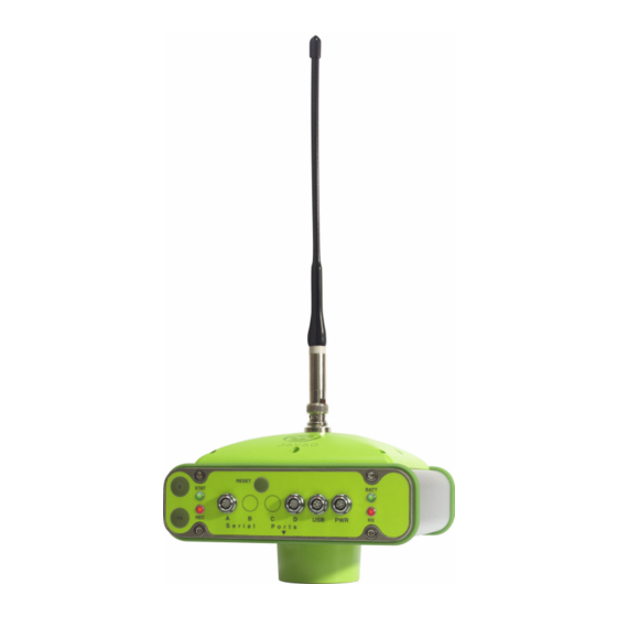
(Figure 1-1). Figure 1-1. Maxor Receiver The Maxor can receive and process both L1 and L2 signals, improving the accuracy of your measuring points and positions. The GNSS component of Maxor receivers means you can access both the GPS (Global Positioning... -
Page 21: Principles Of Operation
(satellite positions as a function of time), to ensure the satellites transmit data properly. • User – The community and military that use GPS/GLONASS receivers and the corresponding satellites to calculate positions. www.javad.com Maxor Operator’s Manual 1-3... -
Page 22: Calculating Positions
DOP number, providing more accurate positioning. • Availability – The availability of satellites affects the calculation of valid positions. The more visible satellites available, the more valid and accurate the position. Natural and man-made objects can block, 1-4 Maxor Operator’s Manual www.javad.com... -
Page 23: Conclusion
The receiver processor controls the process of signal tracking. Once the signal is locked in the channel, it is demodulated and necessary signal parameters (carrier and code phases) are measured. In addition, broadcast navigation data are retrieved from the navigation frame. www.javad.com Maxor Operator’s Manual 1-5... -
Page 24: Maxor Accessory Kit
• Static or dynamic modes Maxor Accessory Kit Although the Maxor can be supplied with a number of different accessories, this manual refers to the standard kit. Unpack the kit contents and check all the items thoroughly. If any item included is damaged or missing, get in touch with your dealer as quickly as possible. -
Page 25: Cables
(http://www.javad.com). The following software will also be useful for operating, caring for and using your Maxor receiver, and may be required for some applications. • FLoader – JNS's firmware loader; available from the JNS website. • Modem-JNS - JNS’s modem configuration software; available from the JNS website. -
Page 26: Literature
• MinPad User's Manual Getting to Know Your Maxor The Maxor is 159 mm wide, 175 mm deep, 90 mm high, weighs ~ 1.6 kg.THe Maxor GGDT is 159 mm wide, 162 mm deep, and 115 mm hightm weighs ~ 1.620 kg (~1.760 kg with UHF modem). -
Page 27: Bluetooth® Module
A combination of software and hardware technology that makes the Maxor mobile, wireless, GNSS receiver that supports a point-to-point serial profile. As such, the Maxor can transfer and synchronize files between the receiver and any other Bluetooth® wireless technology device that supports serial profile, including portable handheld devices and external controllers, Bluetooth®... -
Page 28: Power Board
GNSS Receiver Board The Maxor is supplied depending on the desired receiver functionality with a Euro-80 or Euro-112 card, Maxor GGDT is supplied with board Euro-112T. Table 1-1 lists the options available for these card models. Table 1-1. Euro Card Options... -
Page 29: Battery
GNSS receiver should run at least 17 hours for the Maxor-GD/GG or 14 hours the Maxor-GGD. The Li-Ion batteries used in the Maxor should run at no less than 98% capacity after 500 charging cycles. These batteries do not need to be drained before recharging. -
Page 30: Bottom Panel
I N T R O D U C T I O N Getting to Know Your Maxor Figure 1-2. Maxor Radome Bottom Panel Figure 1-3 shows the Maxor’s bottom panel components. • Antenna Reference Point (ARP) • The GPS/GLONASS external antenna connector (standard configuration) Figure 1-3. -
Page 31: Front Panel
• Vent plug – Equalizes the pressure between the inside of the receiver and the outside environment. • USB – Available on the Maxor GGD with the Euro-112 card and jn the Maxor GGDT with the Euro-112T card, used for high-speed data transfer and communication between the receiver and an external device. -
Page 32: Option Authorization File (Oaf)
• Receiver serial number. • Slant height measure mark (SHMM). Option Authorization File (OAF) Javad Navigation Systems issues an Option Authorization File (OAF) to enable the specific options that customers purchase. An Option Authorization File 1-14 Maxor Operator’s Manual www.javad.com... - Page 33 • Type of signal (standard L1; optional L2) • Memory (standard 0 MB; for Maxor-GD/GG, optional up to 512 MB for Maxor-GGD, optional up to 1 GB) • Update rate standard 1Hz (optional 5, 10, or 20 Hz) •...
- Page 34 Notes: 1-16 Maxor Operator’s Manual www.javad.com...
-
Page 35: Chapter 2. Configuration
Powering the Maxor ........2-2 Charging the Maxor . -
Page 36: Powering The Maxor
The use of external power source allows you to continue using the receiver in case the internal batteries are discharged. The appropriate external power source must provide + 6 to +28 V DC and must 2-2 Maxor Operator’s Manual www.javad.com... -
Page 37: Battery Charger
• Press and hold the Reset key for about one second to ensure that the receiver is in Normal mode for accepting power. • Turn on the receiver by pressing and holding the green power key for about 0.5 seconds. www.javad.com Maxor Operator’s Manual 2-3... -
Page 38: Power Management
PCView exceeds the scope of this manual, but can be found in the PCView Software Manual. The latest copy of this software and the manual can be downloaded from the JNS website (http://www.javad.com). 2-4 Maxor Operator’s Manual www.javad.com... - Page 39 Powering the Maxor To access the tab controlling the power settings of your receiver, take the following steps: 1. Connect your receiver and computer. See “Connecting the Maxor and a Computer” on page 2-9 for this procedure. 2. Start PCView.
-
Page 40: Select Power Output Modes - Ports
Figure 2-6. View Voltages Information • External – displays the external power supply’s voltage. • On Board – displays the voltage drawn by the receiver board. • Battery A – displays the voltage of battery A. 2-6 Maxor Operator’s Manual www.javad.com... -
Page 41: Enable Slots
Figure 2-7. Enable Slots 10. Select and check the Enable Low Power Mode check box to put the receiver’s processor into low power consumption mode (Figure 2-8). Figure 2-8. Activate Low Power Mode 11. Click Apply. www.javad.com Maxor Operator’s Manual 2-7... -
Page 42: Charging The Maxor
A red light indicates less than 10% charge. The Li-Ion batteries used in the receiver should run at no less than 98% capacity after 500 charging cycles. These batteries do not need to be drained before recharging. 2-8 Maxor Operator’s Manual www.javad.com... -
Page 43: Connecting The Maxor And A Computer
To configure, manage files, or maintain the Maxor, you need to connect the receiver and a computer using an RS232 cable, and start PCView. In addition, if an USB port is available on your Maxor, you can use an USB cable and a computer with the JNS USB driver for such connection. -
Page 44: Establishing An Rs232 Cable Connection
Establishing a USB Cable Connection Make sure the computer has JNS’s USB driver installed (available from Support area Free Software section of http://www.javad.com) before continuing. 1. Using the USB cable, connect the USB port on the receiver to a USB port on the computer. -
Page 45: Establishing A Pcview Connection
C O N F I G U R A T I O N Connecting the Maxor and a Computer Establishing a PCView Connection PCView is a personal computer software used to manage the various functions of your receiver. The full range of PCView configuration and function is outside the scope of this manual. - Page 46 C O N F I G U R A T I O N Connecting the Maxor and a Computer –For Bluetooth® connections, disable RTS/CTS handshaking. For RS232 connections enable RTS/CTS handshaking. Figure 2-10. Bluetooth® and RS232 Connection Parameters • For USB connections (Figure 2-11) –Set the Connection mode (Direct).
- Page 47 C O N F I G U R A T I O N Connecting the Maxor and a Computer of the main window of PCView. A timer begins to count up in the lower- right corner as well (Figure 2-12).
-
Page 48: Maxor Configuration
Maxor Configuration PCView is JNS's receiver configuration software, used to configure the various parts of the Maxor receiver. Any settings made using PCView will be saved in the receiver's memory, and will be reflected when you use the MinPad. The full range of PCView configuration and function is outside the scope of this manual. -
Page 49: Receiver Configuration
Figure 2-14. Receiver Configuration Click the MinPad tab, configure the following settings, and click Apply (Figure 2-15 on page 2-16). • Set the Recording interval in seconds. • Set the Elevation mask for Log file in degrees. www.javad.com Maxor Operator’s Manual 2-15... -
Page 50: Receiver Configuration - Minpad Tab
Click the Advanced tab on the Receiver Configuration screen and then click the Multipath Reduction subtab. Enable the following boxes, and click Apply (Figure 2-16 on page 2-17): • Code multipath reduction 2-16 Maxor Operator’s Manual www.javad.com... -
Page 51: Advanced Configuration - Multipath Reduction
Click the Loop Management tab, enable the following boxes, and click Apply (Figure 2-17): • Enable Common Tracking • Static Mode (used for static receivers only, disable if using the receiver as a Rover) Figure 2-17. Advanced Configuration – Loop Management www.javad.com Maxor Operator’s Manual 2-17... - Page 52 Disconnecting the receiver from the computer before exiting will eliminate any possible conflict in the management of your serial ports. Once the receiver is configured, the configuration will remain until you change it either using PCView or clearing the NVRAM. 2-18 Maxor Operator’s Manual www.javad.com...
-
Page 53: Minpad Configuration
C O N F I G U R A T I O N MinPad Configuration MinPad Configuration The Maxor's simple user interface (MinPad) consists of three keys (Power, FN, and Reset) and up to four LEDs (STAT, REC, BATT, and RX) that control and display the receiver's operation (Figure 2-18). -
Page 54: Connection Parameters - Rts/Cts Handshaking
MinPad Configuration You use PCView to configure MinPad settings. Refer to the PCView Software Manual for all possible MinPad configurations. Connect your receiver and computer. See “Connecting the Maxor and a Computer” for this procedure. Start PCView. On the Connection Parameters dialog box, enable RTS/CTS handshaking (Figure 2-19) and then click Connect. -
Page 55: Receiver Configuration - Minpad Tab
File Name Prefix parameter This parameter specifies what prefix will be added to the names of the receiver files created when pressing FN. The prefix can be up to 20 characters long. The default value is log. www.javad.com Maxor Operator’s Manual 2-21... - Page 56 • Values are 0 to 86400 seconds. The default value is zero seconds. • Files (total) - a counter that specifies how many multiple log files must be created in AFRM until this mode automatically turns off. This counter 2-22 Maxor Operator’s Manual www.javad.com...
- Page 57 For more details, see Table 4-1 on page 4-4, and refer to the MinPad User's Manual and PCView Software Manual. www.javad.com Maxor Operator’s Manual 2-23...
- Page 58 Also, if Always is enabled, your receiver will automatically start logging data (to a newly created or an existing file) in the following three cases: 2-24 Maxor Operator’s Manual www.javad.com...
- Page 59 C O N F I G U R A T I O N MinPad Configuration • After pressing the Power key to turn on the receiver. • After resetting the receiver (with PCView or the Reset key). • After taking the receiver out of Sleep Mode. www.javad.com Maxor Operator’s Manual 2-25...
-
Page 60: Radio Configuration
C O N F I G U R A T I O N Radio Configuration Radio Configuration The internal radio in your Maxor can be configured differently depending on your needs and working conditions. The software program required to configure the radio modem differs depending on your receiver configuration, and allows you to: •... -
Page 61: Configuring A Base Station's
Configuring a Base Station’s JNS 2W UHF 410-470 radio transceiver For Maxor, the integrated JNS 2W UHF 410-470 radio transceiver provides TX/RX UHF communications between a Base Station and Rover. To configure the UHF radio modems, have the following ready: •... -
Page 62: Set Radio Link Parameters For A Dedicated Channel
Figure 2-22. Radio Link Tab • JNS – Select this protocol if all of the radio-modems at your jobsite are manufactured by Javad Navigation Systems. • PDL – Select this protocol if you use PDL radio-modem(s) together with JNS radio-modem(s) at the jobsite. - Page 63 (in x10 ms) field will be displayed. In this field enter an integer value between 1 (corresponds to 10 ms) and 50 (corresponds to 500 ms). Once the timeout between incoming data exceeds the specified value, the modem begins data transmission. www.javad.com Maxor Operator’s Manual 2-29...
-
Page 64: Set Radio Link Parameters For Free Channel Scan
“Setting up an RTK Base Station” on page 3-13 and PCView Software Manual. Set Radio Link Parameters for Free Channel Scan 1. Repeat steps 1-9 from “Set Radio Link Parameters for a Dedicated Channel” on page 2-28. 2-30 Maxor Operator’s Manual www.javad.com... -
Page 65: Fcs Tab
6. In the Noise Level field, specify a threshold value for the noise level. There are three levels available: • High – sets the noise level to -70 dBm. Recommended in noisy environments. • Medium – sets the noise level to -85 dBm. Recommended in most environments. www.javad.com Maxor Operator’s Manual 2-31... - Page 66 Station. For how to set up an RTK Base using PCView, refere to “Setting up an RTK Base Station” on page 3-13 and PCView Software Manual. When finished configuring the radio modem, always Warning: disconnect from Modem-JNS before exiting to prevent conflicts with serial port management. 2-32 Maxor Operator’s Manual www.javad.com...
-
Page 67: Configuring A Rover Station's Jns 2W Uhf 410-470 Radio Transceiver
“Setting up an RTK Rover” on page 3-18 or PCView Software Manual. Set Radio Link Parameters for Free Channel Scan 1. Repeat steps 1-9 “Set Radio Link Parameters for Free Channel Scan” on page 2-30. www.javad.com Maxor Operator’s Manual 2-33... -
Page 68: Fcs Tab
Notice: It is recommended to make this parameter greater than the base radio modem’s Time out by 2 to 3 seconds. 2-34 Maxor Operator’s Manual www.javad.com... -
Page 69: Configuring A Base Station's Internal Gsm/Gprs Integrated With 2W Uhf Transceiver With Modem-Jns
2. Click the GSM tab (Figure 2-27). Figure 2-27. GSM Tab 3. In the Mode control, select Slave. 4. In the PIN field, enter a Personal Identification Number (PIN) if required. 5. For the base station, leave the Dial field blank. www.javad.com Maxor Operator’s Manual 2-35... -
Page 70: Configuring A Rover Station's Internal Gsm/Gprs Integrated With 2W Uhf Transceiver With Modem-Jns
If both of your receivers are Maxor with internal GSM/GPRS integrated with 2W UHF transceivers, set Send time to zero. 7. Click the Serial Interface tab and select a baud rate for the modem’s serial port. -
Page 71: Configuring A Single Gsm/Gprs Modem
C O N F I G U R A T I O N Radio Configuration Notice: If both of your receivers are Maxor with internal GSM/ GPRS integrated with 2W UHF transceivers, set Send time to zero. Figure 2-28. GSM Tab 7. -
Page 72: How To Configure A Sigle Gsm/Gprs Modem
1. Connect your receiver and computer using an RS232 cable and appropriate serial ports. In addition, if your Maxor receiver has an USB port, you can use an USB cable and a computer with the JNS USB driver installed (this driver is available to download from Free Software section of Support area on http://www.javad.com/). -
Page 73: How To Configure A Single Gsm/Gprs Modem
The receiver will automatically start working with the GSM modem. How to configure a single GSM/GPRS modem with FieldView Refer to the FieldView User's Manual for how to accomplish this task. www.javad.com Maxor Operator’s Manual 2-39... -
Page 74: Bluetooth® Module Configuration
Create or locate the following folder: C:\Program Files\JNS\BTCONF Download btconf.zip from the JNS website (http://www.javad.com) and unzip it into the BTCONF folder. This file contains Btconf.exe, the executable file for the Bluetooth® module configuration program. To uninstall, or remove, BTCONF, delete any applicable BTCONF directories or folders, and any BTCONF shortcuts. - Page 75 Identification tab (Figure 2-32 on page 2-42) displays the following information: • Bluetooth® name – the name of the Bluetooth® module, set in the Parameters tab. • Bluetooth® address – the unique electronic address for your Bluetooth® module. • Firmware base. www.javad.com Maxor Operator’s Manual 2-41...
- Page 76 To set security parameters (Figure 2-33 on page 2-42), enter and enable the following, then click Apply: • Bluetooth® PIN – enter up to 16 characters to specify a personal identification number for the Bluetooth® module. 2-42 Maxor Operator’s Manual www.javad.com...
- Page 77 Click the Serial Interface tab (Figure 2-35). Enable Echo to display Bluetooth® module replies and corresponding commands on the computer terminal. If needed, click Apply. Figure 2-35. BTCONF Serial Interface Tab Click Disconnect then Exit to quit BTCONF. www.javad.com Maxor Operator’s Manual 2-43...
-
Page 78: Collecting Almanacs
• After loading a new OAF. • After loading new firmware. • After clearing the NVRAM. • Before measuring. The collection and/or update of an almanac can take as long as 15 minutes. 2-44 Maxor Operator’s Manual www.javad.com... -
Page 79: Chapter 3. Setup And Measuring
This chapter describes the following: Maxor Receiver Setup ....... . . 3-2 Measuring with the Maxor . -
Page 80: Maxor Receiver Setup
This section assumes you have already configured your receiver using PCView. 1. Place the Maxor on the appropriate tripod or bipod. 2. Center the receiver over the point at which data will be collected. For most applications, this should be at a location with a clear view of the sky. - Page 81 Figure 3-1 illustrates the antenna offsets. (See Figure 1-3 on page 1-12 and Figure 1-4 on page 1-13 for the exact SHMM location.) 79.5mm Figure 3-1. Maxor GD and Maxor GGD Antenna Offsets • SHMM to ARP vertical offset = 30.5 mm • SHMM to ARP horizontal offset = 79.5 mm Table 3-1 gives the offset values for the receivers.
-
Page 82: External Antenna Setup
4. Press and hold the power key until all lights go out, then release. External Antenna Setup The Maxor can also be used with an external antenna. Follow the steps below to connect an external antenna to the Maxor and measure its offset. -
Page 83: Marant+ Antenna Offset Measurements
Table 3-2. Antenna Offset Measurements Antenna Radius A, Vertical Offset C, Slant Offset MarAnt+ SHMM1 SHMM2 54.3 mm (L1) 26.8 mm (L1) 69 mm 89.7 mm 60.5 mm (L2) 33.0 mm (L2) 0.226 ft 0.294 ft www.javad.com Maxor Operator’s Manual 3-5... -
Page 84: Configuration->Receiver
4. Attach the flexible RF cable from the external antenna to the antenna connector on the bottom panel of the Maxor. 5. Turn on the Maxor and continue with step 3 on page 3-4. The Maxor antenna default is set to Auto, allowing the receiver to detect automatically the available antenna (whether internal or external). -
Page 85: Measuring With The Maxor
6. Click Exit to quit Receiver Configuration window. 7. Click File->Disconnect, then File->Exit. Measuring with the Maxor The Maxor receiver can be used to perform the following types of measuring: • Static • Kinematic • Real-time kinematic (RTK) Static Measuring Static measuring is the classic measuring method, well suited for all kinds of baselines (short, medium, long). -
Page 86: Configuration->Receiver->Minpad
The procedure that follows describes the steps the operator should take to perform a Static Measuring using MinPad. 1. Connect your receiver and computer. See “Connecting the Maxor and a Computer” on page 2-9 for this procedure. 2. Open PCView, click Configuration->Receiver->MinPad and specify the following parameters, then click Apply (Figure 3-5): •... -
Page 87: Advanced->Multipath
S E T U P A N D M E A S U R I N G Measuring with the Maxor 3. Click the Advanced tab and then the Multipath tab, set the following parameters, then click Apply (Figure 3-6 on page 3-9): •... -
Page 88: Kinematic Measuring
S E T U P A N D M E A S U R I N G Measuring with the Maxor • Static mode – enable (disable for Rover receivers) Figure 3-7. Advanced->Loop Management 5. Set up each antenna and receiver as described in “Maxor Receiver Setup” on page 3-2. 6. Begin your measuring. Kinematic Measuring You can use the kinematic measuring method in two ways: •... - Page 89 S E T U P A N D M E A S U R I N G Measuring with the Maxor 2. Using PCView, click Configuration->Receiver->MinPad, and configure the Rover with the following parameters, then click Apply (Figure 3-8): • FN Key Mode, Occupation Mode Switch – enable •...
-
Page 90: Kinematic Continuous
S E T U P A N D M E A S U R I N G Measuring with the Maxor 6. Move the Rover to the next location (measuring point), and press the FN key for less than a second to collect the data in static mode for two to ten minutes. -
Page 91: Real-Time Kinematic Measuring
To configure an RTK Base station using PCView, take the following steps: 1. Set up the Base station receiver's antenna as described in “Maxor Receiver Setup” on page 3-2. 2. Connect an external modem to port D for the Maxor receiver. - Page 92 S E T U P A N D M E A S U R I N G Measuring with the Maxor 7. Click the Set all parameters to defaults button located at the bottom of the Receiver Configuration screen (Figure 3-9).
-
Page 93: Receiver Configuration - Positioning
S E T U P A N D M E A S U R I N G Measuring with the Maxor 9. Select the Positioning tab and set the Position Masks, Elevation mask parameter to 15 (Figure 3-10). Figure 3-10. Receiver Configuration – Positioning 10. - Page 94 S E T U P A N D M E A S U R I N G Measuring with the Maxor Notice: The reference geodetic coordinates you specify on this tab relate to the antenna L1 phase center. Figure 3-11. Base Tab Configuration 11.
- Page 95 S E T U P A N D M E A S U R I N G Measuring with the Maxor Figure 3-12. Base Configuration – Ports 12. Click Apply. The receiver begins sending data to the selected port. If using a Pacific Crest PDL (UHF) external modem, follow these steps...
-
Page 96: Setting Up An Rtk Rover
Use the following steps to set up an RTK Rover station. You should already have programmed the modem. 1. Set up the Rover station receiver's antenna as described in “Maxor Receiver Setup” on page 3-2. 2. Connect your receiver and computer. See “Connecting the Maxor and a Computer”... - Page 97 S E T U P A N D M E A S U R I N G Measuring with the Maxor epoch to which the newly received RTCM/CMR message corresponds) or the current stand-alone position (while waiting for new RTCM/CMR messages coming from the base).
- Page 98 S E T U P A N D M E A S U R I N G Measuring with the Maxor 9. On the main screen, check the LQ field to ensure the receiver obtains differential corrections. Usually, the receiver will start to output the coordinates of the antenna's phase center along with the solution type within 10-30 seconds.
-
Page 99: Chapter 4. Operation
PERATION This chapter describes the following standard Maxor operating procedures: Using MinPad ........4-2 Downloading Files to a Computer . -
Page 100: Using Minpad
Using MinPad Using MinPad The MinPad is a simple interface used to display and control data input and output (Figure 4-1). Figure 4-1. Maxor MinPad Power Key Pressing the power key turns the receiver on and off. Status LED • When the receiver is on and no satellites are tracked, the STAT LED will blink red. -
Page 101: Fn Key And Record Led
FN key, the REC LED becomes red. Release the FN key while the REC LED is red (during the next three seconds). Pressing the FN key for more than eight seconds has no impact. www.javad.com Maxor Operator’s Manual 4-3... - Page 102 Release to start recording (Kinematic or Green Static post-processing occupation mode). Pressed for 5–8 Release to turn serial port A baud rate to seconds 9600 bps. Pressed for > 8 No light No function. seconds 4-4 Maxor Operator’s Manual www.javad.com...
-
Page 103: Battery Led
• Green – indicates greater than 90% charge. • Orange – indicates an intermediate charge. • Red – indicates less than 10% charge. The pattern of blinks of the BATT LED also indicates the source of power. www.javad.com Maxor Operator’s Manual 4-5... -
Page 104: Rx Led
• Blinking once a second – the batteries are being charged. • Blinking once every five seconds – the Maxor uses the internal batteries for power. • Not blinking – the receiver is in Zero Power Mode or the internal batteries are completely discharged and no external power is connected. -
Page 105: Information Modes
• Solid green + red flashes every 0.5 sec. – Modem is during a call and receives/transmits data. Information Modes The Maxor has two information modes: Normal and Extended Information Mode (EIM). Normal In normal mode, the STAT LED indicates the number of tracked satellites and the position's computation status. - Page 106 15 minutes of powering on. • Green - ok • Orange - wait • Red - some tests failed 3. To switch back to normal, press the FN key. 4-8 Maxor Operator’s Manual www.javad.com...
-
Page 107: Downloading Files To A Computer
You should download files as soon as possible after collecting data at the jobsite. PCView provides a File Manager to download files to your computer and delete files from the Maxor. Connect your receiver and computer. See “Connecting the Maxor and a Computer” on page 2-9 for this procedure. Start PCView. -
Page 108: Download Files
To select multiple files, hold down the shift key and click on nonsequential files to select several files at once; or, hold down the Ctrl key and click on individual files. Figure 4-5. Download Files 4-10 Maxor Operator’s Manual www.javad.com... - Page 109 • Green indicator – file has successfully downloaded. Figure 4-6. Download Files – Status Indicators When finished, click Exit on the File Manager dialog box. Continue with other operations. Or, click File->Disconnect, then File->Exit to quit PCView. www.javad.com Maxor Operator’s Manual 4-11...
-
Page 110: Deleting Files
Deleting Files Deleting Files Use the following steps to delete files from your receiver. Connect your receiver and computer. See “Connecting the Maxor and a Computer” on page 2-9 for this procedure. Start PCView. On the Connection Parameters dialog box, enable RTS/CTS handshaking (See Figure 4-2 on page 4-9.) -
Page 111: Checking An Oaf
RS232 cable, a computer, and PCView. Refer to the PCView Software Manual for a more complete description of the PCView software. Connect your receiver and computer. See “Connecting the Maxor and a Computer” on page 2-9 for this procedure. -
Page 112: Option Manager
• yes or no – the option is either enabled or disabled. Figure 4-9. Option Manager When finished, click Exit on the Option Manager screen, then click File- >Disconnect to prevent conflicts with serial port management. 4-14 Maxor Operator’s Manual www.javad.com... -
Page 113: Loading Oafs
O P E R A T I O N Loading OAFs Loading OAFs Javad Navigation Systems dealers provide customers with OAF files. For any OAF related questions, E-mail JNS at options@javad.com. Please have your receiver ID number available (see “Checking Firmware Version” on page 4-21). -
Page 114: Managing Receiver Memory
Managing Receiver Memory Managing Receiver Memory When using the Maxor in static or dynamic applications, you may need to know the amount of memory the receiver's log file occupies. The specific memory size depends on the type of data being recorded. Use the formulas below to compute the approximate size of the receiver's log files. -
Page 115: Clearing The Nvram
(around 15 minutes). Clearing the NVRAM of your receiver will not delete any files already recorded in your Maxor's memory. However, it will reset your receiver settings to factory default values. In addition, the NVRAM keeps information about the receiver file system. Note... -
Page 116: Using Pcview To Clear Nvram
O P E R A T I O N Clearing the NVRAM Using PCView to Clear NVRAM 1. Connect your receiver and computer. See “Connecting the Maxor and a Computer” on page 2-9 for this procedure. 2. Click Tools->Clear NVRAM (Figure 4-11). -
Page 117: Changing Receiver Modes
Zero Power Mode When your Maxor is off, even in Sleep Mode, the power board will continue to draw power from the batteries. This means that if you fully charge your receiver, turn it off and store it, the receiver will drain its battery power in less than two months. - Page 118 4. Press the Reset key for about one second to return to Normal mode. Notice: When the internal batteries have completely discharged and no external power is connected, the receiver will go into Zero Power Mode automatically to prevent the batteries from over discharging. 4-20 Maxor Operator’s Manual www.javad.com...
-
Page 119: Checking Firmware Version
Use PCView to check the firmware version of your receiver. Notice: The Maxor receiver should be loaded with firmware version 2.3 or newer. Connect your receiver and computer. See “Connecting the Maxor and a Computer” on page 2-9 for this procedure. Start PCView. Click on Help->About (Figure 4-12). -
Page 120: About Pcview
This list includes the following, which you will need if you contact JNS or your dealer: • Receiver model • Receiver IDs • Firmware version When finished, click OK, then click File->Disconnect to prevent conflicts with serial port management. 4-22 Maxor Operator’s Manual www.javad.com... -
Page 121: Loading New Firmware
JNS website, to ensure your receiver has the most recent updates. The Maxor uses FLoader, a Windows®-based utility, to load firmware onto the receiver and power boards. You can download FLoader to your computer from the JNS website (http://www.javad.com). -
Page 122: Set Device Type
Capture (recommended) (Figure 4-16). Figure 4-16. Program Tab Settings 4. Browse for and select the receiver board's RAM file and Flash file (Figure 4-16). 5. Click Load and wait until 100% of the files load into your receiver. 4-24 Maxor Operator’s Manual www.javad.com... -
Page 123: Set Device Type
Capture (recommended) (Figure 4-18). Figure 4-18. Program Tab Settings 9. Browse for and select the Power board's RAM file (Figure 4-18). 10. Click Load and wait until 100% of the power board file loads into your receiver. www.javad.com Maxor Operator’s Manual 4-25... -
Page 124: Bluetooth Module Firmware
Then click Get from Device for device information (Figure 4-19). Figure 4-19. Get Device Type 2. Click the Program tab and set the Capture Method to “Soft Break Capture” (recommended) (Figure 4-20 on page 4-27). 4-26 Maxor Operator’s Manual www.javad.com... -
Page 125: Program Tab Settings
(Figure 4-21). Figure 4-21. Bluetooth Firmware Load Complete Notice: If you selected an incorrect file, an error message displays at the bottom of the dialog box. Select the correct file. 5. Click File -> Exit. www.javad.com Maxor Operator’s Manual 4-27... - Page 126 Notes: 4-28 Maxor Operator’s Manual www.javad.com...
- Page 127 ROUBLESHOOTING In general, as long as you follow the maintenance and safety instructions provided in this manual, you should have few problems with your Maxor. This chapter will help you diagnose and solve some common, minor problems you may encounter with your Maxor receiver.
-
Page 128: Things To Check First
• Initialize the file system (click Tools->Initialize file system; this will erase all files inside the receiver). WARNING: Do not attempt to repair equipment yourself. Doing so will void your warranty and may damage the hardware. 5-2 Maxor Operator’s Manual www.javad.com... -
Page 129: Power Problems
TR O U B L E S H O O T I N G Power Problems Power Problems All Maxor receivers are preset in the factory as "Auto Mode" for both the power and charger. If you want to check these settings, Connect your receiver and computer and run PCView (see “Connecting the Maxor and a Computer”... -
Page 130: Receiver Problems
The cable is damaged. Contact your Dealer to replace the cable. Connect your receiver and a computer using a free port (see “Connecting the Maxor and a Computer” on page 2-9) and start The receiver port used PCView. for connection is not in Click Configuration->Receiver->Ports. - Page 131 PCView or other suitable field data collection software. If the receiver should function as a Base, ensure it has the proper configuration. See “Measuring with the Maxor” on page 3-7 for receiver further information. configured as a Base or If the receiver should function as a Rover, ensure it has the proper Rover.
- Page 132 Connect your receiver and a computer and start PCView. See standards used at the “Connecting the Maxor and a Computer” on page 2-9. Base Rover Click Configuration->Receiver->Ports and set the same input/ receivers. output format for both receivers.
- Page 133 (AFRM) parameters” on page 2-22. The receiver has already Delete unnecessary files (see “Deleting Files” on page 4-12). logged 512 files into the Use the AFRM feature. See “Automatic File Rotation Mode internal memory. (AFRM) parameters” on page 2-22. www.javad.com Maxor Operator’s Manual 5-7...
-
Page 134: Bluetooth® Problems
“Bluetooth® Module Configuration” on page 2-40 for details. selected in BTCONF. Connect your receiver and a computer using a free port (see“Connecting the Maxor and a Computer” on page 2-9) and The receiver port used start PCView. for connection is not in Click Configuration->Receiver->Ports. - Page 135 Solutions Connect your receiver and a computer using an RS232 cable (see The receiver’s Slot 3 is “Connecting the Maxor and a Computer” on page 2-9). turned off. Click Configuration->Receiver ->General. In the Turn on/off Slots area, enable the Slot 3 (B) check box.
- Page 136 If you changed settings for your Bluetooth® module, remove it Bluetooth® module from the list of discovered Bluetooth® devices using the settings have Bluetooth® manager program (supplied with the device used to changed. manage the receiver). Repeat the search. 5-10 Maxor Operator’s Manual www.javad.com...
-
Page 137: Obtaining Technical Support
If in doubt which e-mail address to use for your particular question, please send it to support@javad.com. Website The Javad Navigation Systems website provides current information about JNS's line of products. The support area of the website provides access to frequently asked questions, configuration procedures, manuals, e-mail support, etc. - Page 138 Notes: 5-12 Maxor Operator’s Manual www.javad.com...
-
Page 139: Creating Scripts
Tip: For more information on script files, see the PCView Software Manual. Connect your receiver and computer. See “Connecting the Maxor and a Computer” on page 2-9 for this procedure. Start PCView. Click on File->Manual Mode. - Page 140 Click Close editor. Once you have created a script file, Click Load script on the Manual Mode dialog box. Navigate to the folder that contains your script file. Select the appropriate script file and click Send command. A-2 Maxor Operator’s Manual www.javad.com...
-
Page 141: Specifications
Notice: In areas of high multipath, during periods of large PDOP, and during periods of increased ionospheric activity, performance may degrade. Notice: Use robust checking procedures in areas of extreme multipath or under dense foliage. www.javad.com Maxor Operator’s Manual B-1... -
Page 142: Receiver Specifications
Physical Enclosure Aluminum extrusion, rainproof Color JNS Green and Gray Maxor GG/GD/ GGD W:159 x H: 90 x D:175 mm Dimensions Maxor GGDT W:159 x H: 115 x D:162 mm Maxor GG/GD/ GGD 1.6 kg Weight Maxor GGDT 1.620 kg (1.760 kg with UHF modem) - Page 143 165 g (1 battery) Number of built-in 2 batteries batteries Maxor GGDT with JNS 2W UHF 410-470 radio transceiver ~10 hours with 1 W Transmit ON ~7 hours with 2 W Transmit ON ~16 hours with Receive ON ~13...~15 (by continuous call) hours with GSM/GPRS (GSM 900) ON ~14...~15 (by continuous call) hours with GSM/GPRS (GSM 850) ON...
- Page 144 10 years minimum operation External power 1 port Communication Up to four high speed RS232 serial ports, a USB port (Maxor GGD and Ports Maxor GGDT), and an internal Bluetooth communication port. External GPS/GLONASS Antenna, Modem Antenna, 1PPS output Connectors...
- Page 145 Delay mode – 20 msec to 20 sec (depends on latency which receives Latency corrections data from base receiver) Extrapolation – 20 to 30 msec The receiver can record raw data at another interval during RTK Raw Data logging operation www.javad.com Maxor Operator’s Manual B-5...
- Page 146 For L1+ L2, L1 – H: 10mm + 1.0ppm (x baseline length) Kinematic, RTK V: 15mm + 1.0ppm (x baseline length) Post processing: typically 0.3m DGPS DGPS/RTCM based: typically less than 0.5m Cold Start < 60 sec Warm Start < 10 sec Reacquisition < 1 sec B-6 Maxor Operator’s Manual www.javad.com...
-
Page 147: Gps Board Details
L1 GPS, L1/L2 GPS, L1 GLONASS, L1 GPS + L1 GLONASS, WAAS/EGNOS, PCode and Carrier Optional Cinderella days (see page B-9 for details) GPS/GLONASS, L1/L2 C/A and P-Code and Carrier, WAAS/ Tracked Signals EGNOS Tracking Functions Multi-path reduction Code and Carrier www.javad.com Maxor Operator’s Manual B-7... - Page 148 Internal Memory Compact flash card (not removable) Standard – 0 MB Capacity 512 MB (Maxor GD) or up to 1 GB (Maxor GGD), 256 MB of data storage (Maxor GGDT) Logging Time 53 hours (8 MB, 15 sec, L1/L2, 7 satellites) Logging Interval 0.05 to 86400 seconds, depending on purchased options...
-
Page 149: Bluetooth® Module Details
Table B-4 lists the internal JNS UHF modem’s general specifications. Table B-4. Internal JNS UHF Modem Specifications General 410 MHz to 430 MHz / 430 MHz to 450 MHz / 450 MHz to 470 Frequency Range Channel Spacing 25/12.5 kHz www.javad.com Maxor Operator’s Manual B-9... -
Page 150: Optional Gsm/Gprs Module Details
Table B-5 lists the internal JNS UHF modem’s general specifications. Table B-5. GSM/GPRS Module Specifications Operating systems EGSM: 900/1800 MHz; GSM: 850/1900 MHz; TX power 0.6 W (850 MHz); 2 W (900 MHz); 1 W (1800/1900 MHz); B-10 Maxor Operator’s Manual www.javad.com... - Page 151 Table B-5. GSM/GPRS Module Specifications (Continued) GPRS Multi-slot class 8 (4 down; 1 up); Max BR 85.6 Kbps; Class B GSM 07.10 multiplexing protocol; Coding scheme CS1-CS4; Max BR 14.4 Kbps; MO/MT Text and PDU modes; Cell broadcast; www.javad.com Maxor Operator’s Manual B-11...
-
Page 152: Connector Specifications
A P P E N D I X Receiver Specifications Connector Specifications This sections lists Maxor connector details. Radio (Modem) RF Connector The Pacific Crest PDL (UHF) modem connector type (Table B-6) is a BNC Bulkhead Jack RF connector with an Applied Engineering Product p/n of 6501-7051-003. -
Page 153: Serial Rs-232C Connector
7 pin, ODU p/n G80F1C-T07QC00-0000. Figure B-2. RS-232C Connector Table B-9 gives the RS-232C cable connector specifications. Table B-9. Number Signal Name Details Power_OUT Power Output (supplied voltage) Signal ground Clear to send Request to send Receive data www.javad.com Maxor Operator’s Manual B-13... -
Page 154: Usb Connector
The USB connector is a sealed receptacle, 5 pin, ODU p/n G80F1C- T05QF00-0000 (Figure B-3). Figure B-3. USB Connector Table B-10 gives the USB connector specifications. Table B-10. Number Signal Name Details Not used USB_PWR Bus power Ground USB D+ Data plus USB D- Data minus B-14 Maxor Operator’s Manual www.javad.com... -
Page 155: Gps External Antenna Rf Connector
RF input from LNA, 100 mA ANT_IN at 5.0 volts DC output EVENT and 1PPS Connectors (Optional) The EVENT and 1PPS connectors are coaxial female receptacles of BNC series, Kings Electronics part number KC-79-108. These connectors are optional. www.javad.com Maxor Operator’s Manual B-15... - Page 156 Notes: B-16 Maxor Operator’s Manual www.javad.com...
-
Page 157: Safety Warnings
General Warnings Notice: To comply with RF exposure requirements, maintain at least 20cm between the user and the GSM radio modem. WARNING: The Maxor is designed for measuring and measuring related uses (i.e., measuring coordinates, distances, angles depths, recording such measurements). -
Page 158: Internal Battery Pack Warnings
A P P E N D I X Safety Warnings Internal Battery Pack Warnings ANGER EVER ATTEMPT TO OPEN THE MAXOR CASING OR REPLACE THE BATTERIES LITHIUM ION BATTERIES CAN BE DANGEROUS IF MISHANDLED ANGER O NOT INCINERATE OR HEAT BATTERY PACK ABOVE... - Page 159 The owner should periodically test this product to ensure it provides accurate measurements. CAUTION: Inform JNS immediately if this product does not function properly. CAUTION: Only allow authorized JNS warranty service centers to service or repair this product. www.javad.com Maxor Operator’s Manual C-3...
- Page 160 Notes: C-4 Maxor Operator’s Manual www.javad.com...
-
Page 161: Uhf Radio Usage
RTK communications. A 35 Watt base radio will allow your Maxor system to reach distances of up to 12 miles using the standard antenna, depending on local conditions. Distances in the order of 4 to 7 miles (6 to 11 km) can be easily reached. - Page 162 • Use directional antennas and/or repeaters to increase your system's range. Directional antennas concentrate the signal power within a more narrow direction, significantly increasing the range of your system. • Check out the JNS accessory line for various items to elevate your Base radio. D-2 Maxor Operator’s Manual www.javad.com...
-
Page 163: Warranty Terms
2.The warranty against defects in Javad battery, charger, or cable is 90 days. www.javad.com Maxor Operator’s Manual E-1... - Page 164 Notes: E-2 Maxor Operator’s Manual www.javad.com...
Need help?
Do you have a question about the Maxor and is the answer not in the manual?
Questions and answers