Table of Contents
Advertisement
Quick Links
Advertisement
Table of Contents

Related Manuals for Pepperl+Fuchs HD2-DM-A


Summary of Contents for Pepperl+Fuchs HD2-DM-A
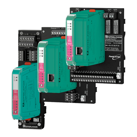
- Page 1 Advanced Diagnostics HD2-DM-A KT-MB-DMA KT-MB-GT2AD.FF KT-MB-GT2AD.FF.IO Manual ®...
- Page 2 Phone: +49 621 776 - 0 E-mail: info@de.pepperl-fuchs.com North American Headquarters Pepperl+Fuchs Inc. 1600 Enterprise Parkway Twinsburg, Ohio 44087 Phone: +1 330 425-3555 E-mail: sales@us.pepperl-fuchs.com Asia Headquarters Pepperl+Fuchs Pte. Ltd. P+F Building 18 Ayer Rajah Crescent Singapore 139942 Phone: +65 6779-9091 E-mail: sales@sg.pepperl-fuchs.com https://www.pepperl-fuchs.com...
- Page 3 Commissioning Wizard ..............15 2.2.3 Diagnostic Gateway Mode (DGW Mode) ......... 15 2.2.4 Field Device Handling ..............16 Product Description ....................17 HD2-DM-A - Advanced Diagnostic Module..........17 Assembly ..................17 3.1.1 3.1.2 Technical Data ................. 17 3.1.3 LED Indication ................. 19 Mounting the Diagnostic Module .............
- Page 4 Manual Setup of a Diagnostic Project with PACTwareTM ....55 5.4.4 Assign Diagnostic Gateway Addresses..........58 5.4.5 Assign HD2-DM-A Addresses............60 5.4.6 Scanning of a Diagnostic Installation for Project Setup ....61 Import of Diagnostic Project from File..........62 5.4.7 5.4.8...
- Page 5 5.6.3 Commissioning Wizard ..............68 5.6.4 System Commissioning ..............68 5.6.5 Segment Commissioning..............69 5.6.6 Generate Report for HD2-DM-A.RO DIP Switch Settings ....70 Diagnostics ....................71 5.7.1 Expert Diagnostics................71 5.7.2 Current Alarms Diagnostics Tab............72 5.7.3 Alarm History Diagnostics Tab ............72 Measured Value....................
- Page 6 Advanced Diagnostics Contents FOUNDATION Fieldbus Integration ................95 FF Device Structure ..................95 Installation ....................97 Alarm Integration ..................98 6.3.1 Alarm Integration with Scheduled Function Block Data ....98 6.3.2 Field Diagnostics................99 6.3.3 Transducer Block Alarms..............99 Operation with Device Descriptions (DD) ..........99 6.4.1 Configuration..................
- Page 7 Advanced Diagnostics Contents Cabinet I/O......................136 Field Diagnostics ..................136 Input Configuration ................... 137 7.2.1 Frequency/Binary Inputs ..............137 7.2.2 Binary Inputs.................. 138 7.2.3 Temperature/Binary Inputs............. 138 7.2.4 Board Humidity ................139 7.2.5 Board Temperature ................ 139 Output Configuration................. 139 On/Off Controllers..................
- Page 8 Advanced Diagnostics Contents HD2-GT-2AD.FF.IO FF Blocks ..............149 8.2.1 ADM_TB Transducer Block ............149 8.2.2 Transducer Block IO_TB ..............156 8.2.3 Multiple Discrete Input (MDI) Function Block ......... 162 8.2.4 Digital input (DI) Function Block ............. 163 8.2.5 Function Block MAI ................ 164 8.2.6 Function Block MDO ..............
- Page 9 Advanced Diagnostics Safety Safety Validity The chapter “Safety” is valid as instruction manual. Specific processes and instructions in this instruction manual require special provisions to guarantee the safety of the operating personnel. Symbols Used This document contains symbols for the identification of warning messages and of informative messages.
- Page 10 Keep the original packaging. Always store and transport the device in the original packaging. Always store the device in a clean and dry location. Observe the permissible storage tempera- ture (see datasheet). Marking HD2-DM-A Fieldbus Power Hub, Advanced Diagnostic Module Pepperl+Fuchs GmbH Lilienthalstraße 200, 68307 Mannheim, Germany Statement of conformity: TÜV 04 ATEX 2500 X...
- Page 11 Advanced Diagnostics Safety The device is only approved for appropriate and intended use. Ignoring these instructions will void any warranty and absolve the manufacturer from any liability. The device must only be operated in the specified ambient temperature range and at the spec- ified relative humidity without condensation.
- Page 12 Advanced Diagnostics General Description General Description Overview Advanced diagnostics provides a set of monitoring tools for FOUNDATION Fieldbus H1 and PROFIBUS PA that simplify the work with the fieldbus physical layer. FieldConnex ® physical layer diagnostics offers the following features: •...
- Page 13 Advanced Diagnostics General Description General System Layout and PCS Integration The advanced diagnostics system consists of diagnostic gateways (DGW) and advanced diag- ® nostic modules (ADM). The ADMs are mounted on FieldConnex Power Hubs or a stand- alone motherboard and are connected to each other and to the GDW using a dedicated diag- nostic bus.
- Page 14 Advanced Diagnostics General Description • PROFIBUS Power Hub integration for systems that use the transparent Pepperl+Fuchs Segment Couplers. This integration is described in detail in the PROFIBUS Power Hub manual. • Simple integrations can be implemented using a volt-free contact. Typically, this integra- tion will be used with one of the other solutions.
- Page 15 Advanced Diagnostics General Description Out of Specification: The value exceeds the specification limits. At least one value vio- lated an IEC 61158-2 limit. Failure: Field devices that were active on the fieldbus during commission- ing and are not active anymore are marked as fail in the user interfaces.
- Page 16 Advanced Diagnostics General Description 2.2.4 Field Device Handling The ADM differentiates between "configured" and "unconfigured" field devices. Field devices are identified based on the device address. • Configured field devices The ADM features a list of field devices that are labeled "configured field devices". All field devices (and the hosts) belonging to the segment are added to the configured field devices list.
- Page 17 Advanced Diagnostics Product Description Product Description HD2-DM-A - Advanced Diagnostic Module General Overview ® The advanced diagnostic module (ADM) is a plug-in module for FieldConnex Power Hubs. Together with the diagnostic gateway and the diagnostic manager software solutions, it sup- ports commissioning, online monitoring and troubleshooting of FOUNDATION Fieldbus or ®...
- Page 18 Advanced Diagnostics Product Description LED PRI PWR green: on, primary bulk power supply con- nected LED SEC PWR green: on, secondary bulk power supply con- nected LED Seg 1...4 yellow: bus activity; red 2 Hz flashing: alarm; red: hardware error Fault signal VFC alarm 1 A, 50 V DC, normally closed DIP-switch...
- Page 19 Advanced Diagnostics Product Description Statement of conformity TÜV 04 ATEX 2500 X Group, category, type of protection, tempera- II 3 G Ex nA IIC T4 Gc ture class Directive conformity Directive 94/9/EC EN 60079-0:2012 , EN 60079-11:2012 , EN 60079-15:2010 International approvals FM approval CoC 3024816, CoC 3024816C...
- Page 20 Advanced Diagnostics Product Description LED Indication Fault Type Remedy PRI PWR or SEC PWR LEDs Supply power failure, possible Connect diagnostic PC and are off. reasons: carry out a complete sys- • No primary and/or second- tem diagnostics: • Bulk power supply ary supply power is avail- switched on and healthy? able...
- Page 21 The stand-alone diagnostic kit consists of an HD2-DM-A plug-in module (see chapter 3.1) and a motherboard to connect the HD2-DM-A to up to 4 segments. It is specially designed to lead the advanced diagnostic features in areas where continuous monitoring of the physical layer is ®...
- Page 22 Advanced Diagnostics Product Description 3.2.1 Assembly Fieldbus Diagnostic Module Extended Version Seg1 Seg2 Seg3 Seg4 162 mm (6.4") 50 mm (1.9") Figure 3.4 Overview KT-MB-DMA Advanced diagnostic module (ADM) Mounting screws Connections for segments SEG1 SEG2 – – – – SEG3 SEG4 Diagnostic bus...
- Page 23 Approved for Class I, Division 2, Groups A, B, C, D, T4 / Class I, Zone 2, AEx/Ex nA IIC T4 3.2.3 Mounting the Stand-Alone Kit and the Advanced Diagnostic Module For mounting the HD2-DM-A diagnostic module, see chapter 3.1.4.
- Page 24 Advanced Diagnostics Product Description Mounting Fieldbus Motherboards on the DIN Mounting Rail In order to mount a motherboard on a DIN mounting rail, proceed as follows: Place the motherboard on the DIN mounting rail. Tighten the fastening screw to attach the motherboard on the DIN mounting rail. Motherboard DIN mounting rail Fastening screw...
- Page 25 • FOUNDATION Fieldbus H1 Provides the core diagnostic data of up to 16 HD2-DM-A ADMs as FOUNDATION Field- bus H1 device. The Ethernet interface can be used in addition to the FF-H1 interface to enhance the functionality of the diagnostic manager and to access the FOUNDATION Fieldbus device locally using a mobile computer.
- Page 26 Advanced Diagnostics Product Description 3.3.1 Assembly LINK/ HD2- 2AD.FF Diagnostic Gateway CH 1 CH 2 Output I: Channel Alarm output diagnostic bus channel 1, volt-free con- tact, NC contact See chapter 4.4.1 Alarm Out Output II: Channel Alarm output diagnostic bus channel 2, volt-free con- tact, NC contact See chapter 4.4.1 Alarm Out...
- Page 27 Advanced Diagnostics Product Description LED: Diagnostic bus channel 2 activity LED: Diagnostic bus channel 1 activity Diagnostic bus channel 1 LED: LINK/ACT LED: Error LED: Power supply Mounting screw (located under diagnostic gateway) Cable and Connection Information • Alarm output / serial / bulk power supply: •...
- Page 28 Advanced Diagnostics Product Description Connection type RJ-45 socket, 8-pin Transfer rate 100 MBit/s Diagnostic Bus Number of Diagnostic Bus Channels Number of Diagnostic Modules/Channel 31 Using Ethernet Interface , 8 Using Fieldbus Interface Termination integrated Cable length/Channel 30 m Indicators/operating means LED ERR red: Hardware fault LED PWR...
- Page 29 Advanced Diagnostics Product Description Electromagnetic compatibility NE 21 Degree of protection IEC 60529 Fieldbus standard IEC 61158-2 Climatic conditions DIN IEC 721 Shock resistance EN 60068-2-27 Vibration resistance EN 60068-2-6 Ethernet IEEE 802.3 Ambient conditions Ambient temperature -40 ... 60 °C (-40 ... 140 °F) Storage temperature -40 ...
- Page 30 Advanced Diagnostics Product Description 3.3.3 LED Indication LINK/ HD2- GT - 2AD. FF .IO Diagnostic Gateway CH 1 CH 2 Power supply Error Link/Activity Diagnostic bus channel 1 Diagnostic bus channel 2 COM, not used Alarm LED Indication Description PWR lights up green The power supply is connected properly ERR lights up red A hardware failure is detected...
- Page 31 • FOUNDATION Fieldbus H1 Provides the core diagnostic data of up to 16 HD2-DM-A ADMs as FOUNDATION Field- bus H1 device. The Ethernet interface can be used in addition to the FF-H1 interface to enhance the functionality of the diagnostic manager and to access the FOUNDATION Fieldbus device locally using a mobile computer.
- Page 32 Advanced Diagnostics Product Description 3.4.1 Assembly PW R ER R LINK/ HD2- GT - 2AD. FF .IO Diagnostic Gateway CH 1 CH 2 CO M AL M Bulk power supply – LED: Error LED: Power supply Output I, selectable: OUT1 Diagnostic bus CH 1, relay, NO contact Output II, selectable: OUT2...
- Page 33 Advanced Diagnostics Product Description I/O Terminal Block Input I Output I Frequency Diagnostic bus CH 1, input 1 Output 1 Binary/ NAMUR input 1 Input II Ground Frequency input A (+) Input V Diagnostic bus CH 1, Binary/ Binary/NAMUR input 5 NAMUR input 2 Input III B (-)
- Page 34 Advanced Diagnostics Product Description All grounding terminals are connected to the shield/screen grounding terminal of the mother- board. The grounding terminals can be used to connect a shield of the I/O or diagnostic bus cables to ground. Input V and Input VI Each diagnostic bus is built of 2 communication lines (+, -) and 2 alarm lines (A, B).
- Page 35 Advanced Diagnostics Product Description Number of Diagnostic Modules/Channel 31 Using Ethernet Interface , 8 Using Fieldbus Interface Termination integrated Cable length/Channel 30 m Indicators/operating means LED ERR red: Hardware fault LED PWR green: Power on Fault signal buzzer on LINK/ACT yellow CH1, CH2 yellow: diagnostic bus activity...
- Page 36 Advanced Diagnostics Product Description Connection only passive load Rated voltage max. 35 V Cable length max. 30 m Line fault detection lead breakage , short-circuit NAMUR Sensor type NAMUR sensor according to DIN EN 60947-6 Connection only passive load Rated voltage max.
- Page 37 Advanced Diagnostics Product Description Output I relay , NO contact Output type selectable: diagnostic bus CH 1 , relay , NO contact Contact loading 250 V AC/ 6 A resistive load Mechanical life 1 x 10 switching cycles Response time turn-on time 7 ms , turn-off time 3 ms Switching frequency 6 min...
- Page 38 Advanced Diagnostics Product Description Climatic conditions DIN IEC 721 Shock resistance EN 60068-2-27 Vibration resistance EN 60068-2-6 Ethernet IEEE 802.3 Ambient conditions Ambient temperature -40 ... 60 °C (-40 ... 140 °F) Storage temperature -40 ... 85 °C (-40 ... 185 °F) Relative humidity <...
- Page 39 Advanced Diagnostics Hardware Installation Hardware Installation Power Hub and Advanced Diagnostic Module ® In order to provide advanced diagnostics for FieldConnex Power Hubs installation ADMs are mounted on the Power Hubs and are connected to each other and to the diagnostic gateway (DGW) via a dedicated diagnostic bus.
- Page 40 / I/O motherboard for diagnostic gate- Depending on the number of segments and the redundancy concept, several motherboards are available. For more information see www.pepperl-fuchs.com. HD2-DM-A Advanced diagnostic module 4.1.1 Installing the Diagnostic Bus The max. length of the diagnostic bus channel is 30 m.
- Page 41 Before mounting the module on the motherboard, a device address must be assigned to the HD2-DM-A module. The address depends on your PCS infrastructure, see chapter 5 or see chapter 6. This assignment is performed using the DIP switch on the device. The DIP switch has 8 switches positioned next to each other.
- Page 42 The KT-MB-DM kit for stand-alone operation enables the installation of the FieldConnex advanced physical layer diagnostics for non-FieldConnex–Power–Hub-based installations. The advanced diagnostic module HD2-DM-A is installed on a motherboard enabling the connec- tion to 4 FOUNDATION Fieldbus H1 or PROFIBUS PA segments. The motherboards are con- nected to each other and to the diagnostic gateway (DGW) using a dedicated diagnostic bus.
- Page 43 • MB-FB-GT.AD.FF / MB-FB-GT.AD.FF.IO: Motherboard for diagnostic gateway / I/O motherboard for diagnostic gate- KT-MB-DMA Kit comprising the following hardware components: • HD2-DM-A: Advanced diagnostic module • MB-FB-DM: Stand-alone motherboard for advanced diag- nostic module 4.2.1 Installing the Diagnostic Bus The maximum length of the diagnoastic bus channel is 30 m.
- Page 44 Before mounting the module on the motherboard, a device address must be assigned to the HD2-DM-A module. The address depends on your PCS infrastructure, see chapter 5 or see chapter 6. This assignment is performed using the DIP switch on the device. The DIP switch has 8 switches positioned next to each other.
- Page 45 Hardware Installation Assigning the Device Address In order to assign an address to the HD2-DM-A, proceed as follows: Set each of the 8 DIP switches at the left side of the module in the correct position to generate a unique address.
- Page 46 Advanced Diagnostics Hardware Installation LINK/ HD2- 2AD.FF Diagnostic Gateway CH 1 CH 2 Figure 4.5 KT-MB-GT2AD.FF grounding terminal PW R ER R LINK/ HD2- GT - 2AD. FF .IO Diagnostic Gateway CH 1 CH 2 CO M AL M Figure 4.6 KT-MB-GT2AD.FF.IO grounding terminal All shield connections are internally connected to the "Shield/Screen GND"...
- Page 47 The alarm contacts are NC contacts. The alarm contacts are closed, if no alarm is active and the contacts are opened if an alarm is active. The volt-free contact alarming is built into the ADM HD2-DM-A and also supported by the diag- nostic gateway. The installation depends on the diagnostic gateway and the integration method...
- Page 48 Advanced Diagnostics Hardware Installation 4.4.1 KT-MB-GT2AD.FF FDS/OPC Integration Each diagnostic bus carries its own volt-free contact lines. These lines are connected on the motherboard to the following terminals: • Channel 1: Alarm output for diagnostic bus channel 1 • Channel 2: Alarm output for diagnostic bus channel 2 The common alarm output terminals are not used.
- Page 49 Advanced Diagnostics FDS/OPC Integration FDS/OPC Integration The FDS/OPC integration uses the open standards OPC and FDT in order to integrate the ® FieldConnex advanced diagnostics into the PCS. It is based on a server component called FieldConnex ® diagnostic server (FDS). The FDS has the 2 following main tasks: •...
- Page 50 Advanced Diagnostics FDS/OPC Integration Installation of Diagnostic Manager with PACTware Installing the Diagnostic Manager with PACTware Make sure you downloaded the software bundle that includes the diagnostic manager and all ® its tools and accessories, including PACTware , the FieldConnex diagnostic server, and the diagnostic gateway configuration tool from www.pepperl-fuchs.com.
- Page 51 Activating the License Before entering the license key, make sure that the diagnostic manager is closed. Choose Start > Programs > Pepperl+Fuchs > Activation Tool to start the Pepperl+Fuchs license activation tool. The license activation tool dialog appears.
- Page 52 ® . If the FDS control center does not start automatically, proceed as follows: Choose Start > Programs > Pepperl+Fuchs > FDS Control Center. The FDS control center appears. Choose Settings. Set the Start control center automatically check box to make sure that the FDS control center starts automatically with Windows ®...
- Page 53 Advanced Diagnostics FDS/OPC Integration After the server has stopped, choose Start FDS to restart the server with the updated settings. The FDS status icon in the taskbar turns green and the FDS is running with the updated set- tings. Choose Hide to minimize the FDS control center into the task bar. Caution! Network Connection Problems The diagnostic server is not connected to the network.
- Page 54 Advanced Diagnostics FDS/OPC Integration The following settings can be made: Control center settings Description Start the control center automatically Every time the PC starts, the control center server starts, too. Minimize the control center on startup The control center starts without the frontend application.
- Page 55 Advanced Diagnostics FDS/OPC Integration Control center settings Description Adjust firewall to allow remote access Edit the firewall settings for the FDS server. Read host name via OPC Enter the host name. The host name is used by OPC clients to find the FDS. Project Setup A diagnostics project can be set up in either of the following ways: •...
- Page 56 Drag the FDS Port entry from the device catalog section on the FieldConnex Diagnostic Server entry in the project section. Select the Device folder in the device catalog. Drag the HD2-DM-A entry from the device catalog section on the FDS Port entry in the project section. ® Right-click the FieldConnex Diagnostic Server in your project section and select Parameter.
- Page 57 Advanced Diagnostics FDS/OPC Integration Figure 5.6 FieldConnex ® Diagnostic Server (FDS) parameter tab If PACTware and FDS are running on the same system, select Local for the FDS Location. If the FDS is running on a different system, for example in a remote application structure, select Remote for the FDS location and enter the IP address or DNS name of the remote PC.
- Page 58 Advanced Diagnostics FDS/OPC Integration Figure 5.8 Diagnostic project Choose Apply to confirm changed settings. Note For fast creation of projects with a huge number of advanced diagnostic modules (ADM): Build one FDS port with 62 diagnostic modules. if supported by the FDT software, you can use copy &...
- Page 59 Advanced Diagnostics FDS/OPC Integration Figure 5.11 Port Properties Choose Apply to confirm changed settings. IP address and tag of the Diagnostic Gateway are assigned to the port. Assigning Diagnostic Gateway Addresses (Option 2) ® Right-click the FieldConnex Diagnostic Server in the project area and choose Connect. ®...
- Page 60 Figure 5.16 Assigned gateway Choose Apply to confirm changed settings. 5.4.5 Assign HD2-DM-A Addresses Registering the Device Address of Diagnostic Modules Each advanced diagnostic module (ADM) has a device address that is assigned directly on the device. See chapter 4.1.2...
- Page 61 Start PACTware Choose File > New to create a new project. Choose View > Device Catalog to open the device catalog. Open the PEPPERL+FUCHS GmbH device folder. Figure 5.18 Structure in the PACTware device catalog Select the Driver folder.
- Page 62 Scan Limit and Upper Scan Limit fields. Only HD2-DM-A addresses within the set limit will be scanned. This option can speed up the scanning process if only a few HD2-DM-A modules within a small address range are used in a project.
- Page 63 PACTware device catalog is up-to-date. Start PACTware Open a PACTware diagnostic project. Choose View > Device Catalog to open the device catalog. Open the PEPPERL+FUCHS GmbH device folder. Figure 5.25 Structure in the PACTware device catalog...
- Page 64 Advanced Diagnostics FDS/OPC Integration Select the Driver folder. Figure 5.26 Device overview of the Driver folder ® Drag the FieldConnex Diagnostic Server entry from the device catalog section on the HOST PC entry in the project section. Right-click the FieldConnex ®...
- Page 65 Note Some functions and features are available only if the latest firmware version is installed on the HD2-DM-A module. A firmware supporting all features is integrated with this DTM and can be installed on any HD2-DM-A hardware. See chapter 7.11...
- Page 66 This interface enables detailed access to all possible See chapter 5.10 settings of the HD2-DM-A. It is for advanced parameter- ization and can be used to adjust the HD2-DM-A to some more seldom use cases not covered by the auto- matic tools like the commissioning wizard.
- Page 67 Advanced Diagnostics FDS/OPC Integration Figure 5.29 Online parameterization window General diagnostic module information Quick start section System and segment status information Function tabs 5.6.2 Settings The Settings tab enables you to adjust segment settings, for example the fieldbus type and the recording intervals for the long-term history storage.
- Page 68 Advanced Diagnostics FDS/OPC Integration 5.6.3 Commissioning Wizard The commissioning wizard is a tool for fast and easy system setup with advanced diagnostic modules (ADM). It guides the user through the system and segment set up and determines the system and segment data of your fieldbus installation. Based on this information, the commis- sioning wizard proposes limit values for all system, segment, and field device alarm values.
- Page 69 Advanced Diagnostics FDS/OPC Integration If necessary, you can modify these values before storing them on the advanced diagnostic module. Note that the out-of-specification alarm for the primary and secondary power supply will be enabled automatically by default. Choose Next. System warning and alarm limit values are now stored on the diagnostic device. Figure 5.32 System commissioning succeeded Choose Restart to confirm changed settings and to return to the commissioning wizard start...
- Page 70 Generate Report for HD2-DM-A.RO DIP Switch Settings Once commissioning of all 4 segments is complete, the commissioning wizard supports gener- ation of a report with the correct DIP switch settings for the HD2-DM-A.RO module. Generating a HD2-DM-A.RO Settings Report In order to generate a settings report for the HD2-DM-A.RO module, proceed as follows: Open the commissioning wizard.
- Page 71 Advanced Diagnostics FDS/OPC Integration Diagnostics The diagnostics function is for troubleshooting after an alarm of the advanced diagnostic mod- ule (ADM) appeared in the process control system (PCS). It displays the currently active expert messages, as well as all active alarms and a history of the last 500 alarms detected by the ADM.
- Page 72 Advanced Diagnostics FDS/OPC Integration 5.7.2 Current Alarms Diagnostics Tab On the current alarms tab all active advanced diagnostic module (ADM) alarms are displayed. This tab shows all the active alarms from which the expert messages that are displayed on the expert diagnostics tab are derived.
- Page 73 Advanced Diagnostics FDS/OPC Integration Alarm Icon Description Each alarm in the alarm history column is shown with date, time, address, and type. The alarm icon indicates whether the alarm is still active or whether it is inactive, i.e., the alarm situation is already over.
- Page 74 Advanced Diagnostics FDS/OPC Integration Filter On/Off Use the Filter On/Off button to activate or deactivate the filtered view. Figure 5.39 Alarm history toolbar and filter settings Exporting the Alarm History Note The system always saves the complete history, independent of the filter settings.
- Page 75 Advanced Diagnostics FDS/OPC Integration Measured Value 5.8.1 System & Segment Measurement The system & segment measurement function allows for fast validation of a new or reworked fieldbus installation. It provides a brief overview of the segment health and enables you to per- form a detailed analysis.
- Page 76 Advanced Diagnostics FDS/OPC Integration Figure 5.41 Signal level Current value Range for excellent value (green) Range for good value (blue) Range for exceeded value (yellow) Maximum value occurred during operation Minimum value occurred during operation Magnifying Glass Click on the magnifying glass to see current field device data. Figure 5.42 Magnifying glass 5.8.2...
- Page 77 Advanced Diagnostics FDS/OPC Integration 5.8.3 Field Device Measurement The field device measurements tab features a table that offers a live view of the essential phys- ical layer values. Figure 5.44 Field device measurements tab 5.8.4 Fieldbus Statistics The fieldbus statistics tab provides a statistical overview of the communication frames received, errors, and other fieldbus values.
- Page 78 The snapshot explorer simplifies administration and enables the printout of existing snapshots and reports. These reports can be printed or exported as an image, text, PDF document, or diagnostic module snapshot (DMS) file. See chapter 5.8.5 Note DMS is a file format for data exchange created by Pepperl+Fuchs.
- Page 79 Advanced Diagnostics FDS/OPC Integration 2 different templates can be selected: A clearly arranged default template and a compact tem- plate that contains the same information using less space. You can export the report to Micro- ® soft Excel. This spreadsheet enables you to generate diagrams and perform individual calculations based on the report data.
- Page 80 Advanced Diagnostics FDS/OPC Integration Button Name Result Zoom out Reduce the report. Zoom 100% View of the report of 100 %. Fit to height Fit the view of the report on the height. Fit to width Fit the view of the report on the width. First page Go to the first page of the report.
- Page 81 Advanced Diagnostics FDS/OPC Integration Opening the Advanced Parameterization In order to open the advanced parameterization window, proceed as follows: Right-click the Advanced Diagnostic Module in the project section. Choose Additional Functions > Advanced Parameterization. The advanced parameterization window appears. Figure 5.49 Advanced parameterization start window General diagnostic module information Function tabs...
- Page 82 Advanced Diagnostics FDS/OPC Integration Right-click the Advanced Diagnostic Module in the project section and choose Parameter > Parameterization. The parameterization window appears. Figure 5.50 Parameterization start window General diagnostic module information Function tabs Segment/field devices are selectable via tree. The preceding icon shows diagnostic state of field device.
- Page 83 Advanced Diagnostics FDS/OPC Integration Note For more information on the parameters, see chapter 5.8. 5.10.1 Field Device Handling The advanced diagnostic module (ADM) classifies the field devices as configured field devices and unconfigured field devices. See also see chapter 2.2.4. The advanced parameterization allows for either of the following configured device list actions: •...
- Page 84 Advanced Diagnostics FDS/OPC Integration Select the Field Devices tab. Choose Add new Field Device in the configured field devices section. Figure 5.52 Configured field devices section The new field device is located in the configured field devices list. Choose Apply. Removing a Field Device In order to remove a field device, proceed as follows: Right-click the Advanced Diagnostic Module in the project section and choose Additional...
- Page 85 Advanced Diagnostics FDS/OPC Integration 5.11 History Export 5.11.1 Long-Term History The long-term history function enables you to collect and store data in well-defined recording intervals. The minimum and maximum values of each measured value within the recording interval are stored as 1 data set. Recording intervals can range from 4 hours up to 7 days. Note The data storage is limited to 100 data sets.
- Page 86 Advanced Diagnostics FDS/OPC Integration Figure 5.54 Export type and export settings Choose Next. After the export is complete, you can close the export function or choose Restart to export the long-term history for another segment. 5.11.3 Excel Export Feature The diagnostic manager provides feature for exporting history data to Microsoft ®...
- Page 87 Advanced Diagnostics FDS/OPC Integration 5.12 Fieldbus Oscilloscope 5.12.1 Oscilloscope Recording Settings The built-in oscilloscope enables in-depth analysis of the fieldbus signal level during a defined time period, for example, if a specific telegram type was detected or if communication issues occurred.
- Page 88 Advanced Diagnostics FDS/OPC Integration Recent Recordings All oscilloscope recordings taken during one session are shown in the recent recordings sec- tion. Note If you close the oscilloscope dialog, all unsaved recordings are lost. 5.12.2 Start Oscilloscope Recording Starting the Recording In order to start the oscilloscope recording, proceed as follows: Right-click the Advanced Diagnostic Module in the project section.
- Page 89 Advanced Diagnostics FDS/OPC Integration 5.12.3 Trigger Description To make sure that the triggered frame is valid, every trigger event occurs at the end of the frame. Trigger Events for FOUNDATION Fieldbus Name Result Pass Token to address Trigger if the specified addresses send frames after receiving a pass token.
- Page 90 Advanced Diagnostics FDS/OPC Integration Name Result Maintenance required by address Triggers when one of the parameters noise, jit- (available since diagnostic manager version ter or signal level gets into state maintenance 1.3) required. Note: Amplitude, recording length, and pre- trigger time are set automatically independent from the settings here.
- Page 91 Advanced Diagnostics FDS/OPC Integration Oscilloscope Toolbar Button Name Result Move Grip and move the graph. Press and hold the left mouse button. Horizontal marker Measure the time difference. Press left mouse button to set the first marker and press the right mouse button to set the last marker.
- Page 92 Advanced Diagnostics FDS/OPC Integration 5.13 Firmware Update The firmware update function enables you to benefit from the latest software developments. Firmware Update Warning! Connection Loss In some situations, the advanced diagnostic module (ADM) disconnects during the update process. Do not try to reconnect manually. The ADM recon- nects automatically after a short time.
- Page 93 Advanced Diagnostics FDS/OPC Integration 5.14 FDS Diagnostics The FSD DTM offers a diagnostics view. This diagnostics gives an overview of all currently active alarms for the segments connected to the FDS, as well as the last time an alarm was active for a segment.
- Page 94 Advanced Diagnostics FDS/OPC Integration 5.15 FDS Reporting Wizard The FDS reporting wizard allows creating reports of all segments connected to an FDS. Cur- rently, one report type is supported: • Surge protector status ® If you use FieldConnex surge protectors with diagnostics, this report gives you an overview of all currently detected issues related to the surge protectors.
- Page 95 FOUNDATION Fieldbus Integration The FOUNDATION Fieldbus integration is based on an FF-H1 field device inside the diagnostic gateway. These devices map the data of up to 16 HD2-DM-A modules to FOUNDATION Field- bus data structure. Both the measurement data and the expert system evaluations of the data are available inside the data structures of transducer blocks.
- Page 96 The diagnostic gateway FF-H1 field device contains 16 transducer blocks for ADMs. Each of these transducer blocks includes the 4 segments supported by an HD2-DM-A. The ADMs are mapped to the transducer blocks based on their address. The address is set using a DIP switch located on the module.
- Page 97 Note The devices can be connected to any of the 2 diagnostic bus channels. For best performance connect the same number of HD2-DM-A to each diagnostic bus channel. Installation Typically, the FF-H1 field device built into the diagnostic gateway is connected to the host of a PCS, using FF-H1 as every other FF-H1 field device.
- Page 98 Advanced Diagnostics FOUNDATION Fieldbus Integration FF-H1-over-Ethernet Connection During commissioning of a plant, the host may not be available yet, but commissioning of the physical layer is already being executed. For these use cases, a PC (e.g., laptop) can be con- nected to the diagnostic gateway using Ethernet.
- Page 99 Advanced Diagnostics FOUNDATION Fieldbus Integration ADM Status (MDI Function Blocks) Add 1 or 2 DGW-FF multiple digital input (MDI) function blocks to your schedule. If you use 1 ... 8 ADMs, 1 MDI is sufficient. If you use 9 ... 16 ADMs, 2 MDI function blocks are required.
- Page 100 Advanced Diagnostics FOUNDATION Fieldbus Integration 6.4.1 Configuration It is recommended to use the commissioning wizard for configuration of the segment, since this is the fastest and safest way of adjusting the maintenance limits. However, it is also possible to configure a segment manually; all necessary settings are available as FF parameters. For sys- tems that do not support all EDDL (DD5) features, a list of parameters of the ADM_TB is avail- able.
- Page 101 System • Block tag: Tag of the ADM_TB. • Serial number: Serial number of connected HD2-DM-A module. • Software revision: Software revision of connected HD2-DM-A module. • Motherboard type: Motherboard the module is mounted on. •...
- Page 102 Advanced Diagnostics FOUNDATION Fieldbus Integration Segment Overview • Segment tag: Tag of the segment • Segment mode: Current segment mode (disabled, non-commissioned, commissioned) • Segment status: Overall segment diagnostics quality • Active diagnostics: Expert system messages about the current status of the segment. The message describes the phenomenon detected on the fieldbus.
- Page 103 Follow the instructions of the wizard. Identify Diagnostic Module (Flash LEDs) Method also supported by DD4. This method causes the HD2-DM-A module to have all LEDs flashing for identification purpose. ADM Firmware Update The DGW-FF has an ADM firmware built in.
- Page 104 FieldConnex diagnostic man- ager software package. If you have downloaded the FieldConnex diagnostic manager from the internet, a license key can be ordered through your local Pepperl+Fuchs representative. Note Upgrade Information After upgrading from diagnostic manager version 1.x to version 2.x, activate the new version...
- Page 105 FOUNDATION Fieldbus Integration License Activation Before entering the license key, ensure that the diagnostic manager is closed. Choose Start > Programs > Pepperl+Fuchs > Activation Tool to start the Pepperl+Fuchs license activation tool. The license activation tool window appears. Figure 6.2 License activation tool Enter your license key.
- Page 106 This interface enables detailed access to all possible settings See chapter 6.8.1 of the HD2-DM-A. It is for advanced parameterization and can be used to adjust the HD2-DM-A to some more seldom use cases not covered by the automatic tools like the commission- ing wizard.
- Page 107 Advanced Diagnostics FOUNDATION Fieldbus Integration The overview also shows if the actual mode of a block is not equal to the normal mode. All unused blocks, e.g., unused function blocks, or ADM transducer blocks with no ADM con- nected, are usually set to out-of-specification (OOS) in order to exclude them from any sum- mary diagnostics.
- Page 108 Advanced Diagnostics FOUNDATION Fieldbus Integration Commissioning Segments Start the commissioning wizard. An overview is shown with information on which segments are not commissioned yet: In order to start commissioning, select a segment. The segment topology window appears:...
- Page 109 Advanced Diagnostics FOUNDATION Fieldbus Integration Enter segment topology settings to refine the diagnostics of the segment you intend to commission. Click Next.
- Page 110 Advanced Diagnostics FOUNDATION Fieldbus Integration The field device tags window appears: Enter field device tags manually or click Import Field Device Tags. Selecting Import Field Device Tags initiates the reading of the field device tags by observ- ing the communication on the segment. In order to import segment and device tags from the process control system (PCS) , use the Tag Import Wizard instead.
- Page 111 Advanced Diagnostics FOUNDATION Fieldbus Integration Click Next. The diagnostic data overview window appears. It provides basic diagnostics of the segment measurements based on the topology information provided in the topology settings window: Eliminate possible problems by using the information given in the segment diagnostics table. To start the commissioning, click Next.
- Page 112 Advanced Diagnostics FOUNDATION Fieldbus Integration The commissioning wizard records physical layer data to create a snapshot of the current segment state. This may take a few seconds. After recording the result is displayed:...
- Page 113 Advanced Diagnostics FOUNDATION Fieldbus Integration Enter a report description. You may also select the option to include characteristic oscilloscope recording fragments for each field device into the report. The actual snapshot report is shown. The report is stored in the DTM persistence and can be reviewed or printed anytime later in the snapshot explorer.
- Page 114 Advanced Diagnostics FOUNDATION Fieldbus Integration Click Next. The advanced diagnostic module's configuration window appears. Based on the snapshot report, maintenance required limits for all measured values are calculated. Review or optimize the calculated values, if required.
- Page 115 Advanced Diagnostics FOUNDATION Fieldbus Integration To store the calculated limits in the device, click Next. The limits are stored. The commissioning is complete.
- Page 116 Advanced Diagnostics FOUNDATION Fieldbus Integration 6.8.3 Diagnosis The diagnosis window provides information on all currently active alarms of the diagnostic gateway. For the function blocks, resource block, and the IO transducer block, all available diagnostic functions are shown. The ADM transducer blocks additionally include the diagnostic messages of the expert system.
- Page 117 Advanced Diagnostics FOUNDATION Fieldbus Integration 6.8.4 Measured Value The measured value window provides easy access to the measurement data of the diagnostic gateway. The function blocks and the IO transducer blocks show the current I/O data. The ADM transducer blocks include a more advanced view of the physical layer data of the connected FF-H1 segments.
- Page 118 Advanced Diagnostics FOUNDATION Fieldbus Integration Figure 6.3 Signal level Current value Range for excellent value (green) Range for good value (blue) Range for exceeded value (yellow) Maximum value occurred during operation Minimum value occurred during operation Magnifying Glass Click on the magnifying glass to see current field device data. Figure 6.4 Magnifying glass...
- Page 119 Advanced Diagnostics FOUNDATION Fieldbus Integration Showing specific field device measurements In order to show specific field device measurements, click the corresponding magnifying glass in the last column. Figure 6.5 Sytem & Segment Measurements tab in non-commissioned mode...
- Page 120 Advanced Diagnostics FOUNDATION Fieldbus Integration Figure 6.6 Sytem & Segment Measurements tab in commissioned mode...
- Page 121 Advanced Diagnostics FOUNDATION Fieldbus Integration Field Device Signal Level The field device signal level tab shows a graphical overview of the measured field device signal levels. For a detailed description of the bar colors, see the system & segment measurements tab description.
- Page 122 Advanced Diagnostics FOUNDATION Fieldbus Integration Creating a Snapshot In order to create a snapshot, proceed as follows: Right-click the Advanced Diagnostic Module in the project section. Choose Measured value. The system & segment measurements window appears. Choose Create Snapshot or Create Snapshot including Oscilloscope Recordings.. The second option includes characteristic oscilloscope recording fragments for each field device into the report.
- Page 123 Advanced Diagnostics FOUNDATION Fieldbus Integration 6.8.6.1 Long-Term History The long-term History function enables you to collect and store data in well-defined recording intervals. The minimum and maximum value of each measured value within the recording inter- val are stored as one data set. Recording intervals can range from 4 hours up to 7 days. Note The data storage is limited to 100 data sets.
- Page 124 Advanced Diagnostics FOUNDATION Fieldbus Integration Select the required file format in the Export Type section and enter a file name in the Filename field. Figure 6.8 Export type and export settings 6.8.6.3 Excel Export Feature ® The diagnostic manager provides feature for exporting history data to Microsoft Excel that enables fast and easy data exchange and reformatting of your physical layer data.
- Page 125 (DMS) file. Note DMS is a file format for data exchange created by Pepperl+Fuchs. 2 different templates can be selected: A clearly arranged default template and a compact tem- plate that contains the same information using less space. You can launch the report using Mic- ®...
- Page 126 Advanced Diagnostics FOUNDATION Fieldbus Integration 6.8.7.1 Snapshot Toolbar Button Name Result Open Open a saved report. Copy to (Export) Copy the selected report to another location. File types: PDF, RTF, TXT, DMS Copy all to (Export all) Copy all reports to another location. File type: DMS Delete Delete the selected report.
- Page 127 Advanced Diagnostics FOUNDATION Fieldbus Integration Importing Tags in General Launch the tag import wizard. In order to create a new topology, choose Create a new topology. The wizard clears all tags saved on the DGW-FF. In order to update tags already loaded, choose Update existing project topology. The wizard assigns imported tags to the currently existing tags based on the segment tag.
- Page 128 Advanced Diagnostics FOUNDATION Fieldbus Integration Select the PCS file to be imported and click Next. The segment selection list shows all segments found in the imported PCS file. Select the segments that are attached to the DGW-FF and click Next. The software assigns the segments to the ADMs automatically.
- Page 129 Advanced Diagnostics FOUNDATION Fieldbus Integration In order to change the default assignment, edit the ADM addresses. Click Next. The software sets the ADM_TB block tags and the segment tags according to the imported data. The software also creates a configured field device for each imported field device tag and assigns the device tag to this device.
- Page 130 Advanced Diagnostics FOUNDATION Fieldbus Integration Right-click on control network and choose Export. Enter the file name and save the file. During import, the tags are assigned to the ADM transducer blocks in the following way: FF-H1 cards are assigned from the lowest to the highest card number to the transducer blocks. Since a DeltaV H1 card has 2 segments, and an ADM has 4 segments, the cards are assigned using the following algorithm: •...
- Page 131 Advanced Diagnostics FOUNDATION Fieldbus Integration...
- Page 132 Advanced Diagnostics FOUNDATION Fieldbus Integration 6.8.9.3 Export Tags from Yokogawa Plant Resource Manager Exporting Tags from Yokogawa Plant Resource Manager Start the plant resource manager (Start > All Programs > YOKOGAWA PRM > Plant Resource Manager). Choose File > Export > Maintenance Info. The Export Maintenance Info window appears.
- Page 133 Advanced Diagnostics FOUNDATION Fieldbus Integration Select Browse. The Device Selection window appears.
- Page 134 Advanced Diagnostics FOUNDATION Fieldbus Integration Select all FOUNDATION Fieldbus devices and click OK. The export maintenance info window appears. Activate Device and click OK. The export starts. After the export has finished, click Close. ALF111 devices are assigned to ADM transducer blocks from low to high device path.
- Page 135 Advanced Diagnostics FOUNDATION Fieldbus Integration 6.8.10 Reporting Wizard The FDS reporting wizard allows creating reports on all segments connected to a diagnostic gateway. Currently, one report type is supported: • Surge protector status ® If you use FieldConnex surge protectors with diagnostics, this report provides an overview of all current issues that are related to surge protectors.
- Page 136 Advanced Diagnostics FOUNDATION Fieldbus Integration...
- Page 137 Advanced Diagnostics Cabinet I/O Cabinet I/O Besides ADM access functionality, the diagnostic gateway KT-MB-GT2AD.FF.IO provides I/O functions mainly for cabinet management applications. The following inputs and outputs are available: • Inputs: • 2 binary inputs that can also be used as frequency inputs. •...
-
Page 138: Default Mapping Offspec
Advanced Diagnostics Cabinet I/O Condition Description Default Mapping IO Out of Specification Any bit in Offspec IO_TB.FD_OOS_ACTIVE is set when IO_TB has the target mode "AUTO" IO Maintenance Required Any bit in IO_TB.FD_MR_AC- Maintenance Required TIVE is set when IO_TB has the target mode "AUTO"... - Page 139 Advanced Diagnostics Cabinet I/O • High Maintenance Required: If the currently measured frequency value is higher than the High-Maintenance–Required limit, the field diagnostics IO_TB–Maintenance–Required condition is triggered. • Low Maintenance Required: Like High Maintenance Required, but for measured fre- quency lower than the Low–Maintenance–Required value. •...
- Page 140 Advanced Diagnostics Cabinet I/O • Low Out of Specification: Like High Out of Specification, but for measured temperature lower than Low-Out-of-Specification value. • Hysteresis: In order to avoid flickering of diagnostics, a hysteresis value can be config- ured. • Unit: Select the unit for temperature measurement. 7.2.4 Board Humidity •...
- Page 141 Advanced Diagnostics Cabinet I/O • Not connected: The output is not used • FF channel: The output is directly controller using an FF function block. This option is only avail- able for the FF integration • Binary input *: The output is directly controlled by a binary input. Any of the binary inputs 1 ... 8 can be used.
- Page 142 Advanced Diagnostics Cabinet I/O • Input: A selector for an analog input value. Available options are: • Temperature input 1 • Temperature input 2 • Temperature input 2 - temperature input 1 (temperature difference) • Motherboard temperature • Motherboard humidity •...
- Page 143 Advanced Diagnostics Cabinet I/O 7.6.1 Configuring Typical Cabinet Management Applications Manually Using Cooling Control Select an unused relay contact output and connect a cooling device (e.g., ventilator) to it. Select an unused on/off controller and configure it as follows: Options: Not inverted On level: Temperature level at which the output is supposed to be switched ON.
- Page 144 Advanced Diagnostics Cabinet I/O Select an unused on/off controller and configure it as follows: Options: Invert On level: Temperature level at which the output is supposed to be switched OFF (Note: Inverted output!) Off level: Temperature level at which the output is supposed to be switched ON (Note: Inverted output!) Input selection: Select the temperature input to be used as reference temperature.
- Page 145 Measured Values / Parameters 8.1.1 Board Type Board Type Detection The type of the board on which the HD2-DM-A is installed is detected. Board Redundancy Detection Detects whether the HD2-DM-A is installed on a redundant board or not. 8.1.2 Communication Active Communication activity is detected if any valid frames (Preamble, SOF, EOF) are detected.
- Page 146 Advanced Diagnostics Appendix Signal DC Power Supply Figure 8.1 Fault wiring DC unbalance An undetected unbalance can cause communication issues and a lack of electromagnetic compatibility stability. Note A single pole-to-shield fault is not critical. But if a second pole-to-shield-fault happens at the same time, corruption of the communication signal and high crosstalk levels can occur between the 2 affected segments.
- Page 147 Advanced Diagnostics Appendix 1 bit time 0.5 bit time 0.5 bit time Figure 8.2 Bit cell jitter Reference event; first zero crossing point Actual zero crossing point Bit cell jitter, deviation from the ideal timing Ideal zero crossing point Segment or Field Device Jitter This parameter monitors the current maximum jitter of all active devices connected to the seg- ment.
- Page 148 Advanced Diagnostics Appendix 8.1.9 Noise Definition Noise is an undesired disturbance within the signal frequency band. Noise appears with differ- ent characteristics. A high noise level causes communication problems and a lack of opera- tional reliability. Segment noise is the maximum noise of all field device noise or the noise measured if no field device is communicating.
- Page 149 Advanced Diagnostics Appendix Type Value Precision +/- 5% Measuring range 0 ... 40 V 8.1.12 Signal Level The current peak–to–peak signal level of all field devices is measured and shown for each field device, as well as the current maximum and minimum value for the segment. Type Values Precision...
- Page 150 Advanced Diagnostics Appendix MB* - Mother- Values board MB-FB-DMA DART Active field devices Unbalance Communication errors statistic Field device polarity Signal level Trunk surge protector alarm Device coupler alarm HD2-GT-2AD.FF.IO FF Blocks The column "Char." shows which characteristics or conditions are applicable to this parameter. •...
- Page 151 Advanced Diagnostics Appendix Parameter Char. Description Record, S, W, SYSTEM HISTORY_PERIOD: History period of the ADM. Controls the number of times the ADM writes a history entry to its non-volatile memory. History can be read via DTM function "History export". FLASH_LEDS: Causes the ADM device to have all LEDs flashing for identifi- cation purpose.
- Page 152 Advanced Diagnostics Appendix Parameter Char. Description EXPERT_MSG_(N): Expert message. For detailed explanation, . Record, W, S, SEG- H1_TAG: Segment tag MENT_(X)_S TATIC H1_MODE: Segment mode • Disabled • Non commissioned (default) • Commissioned PS_MODULE_SUPERVISION: Enables diagnostics of power supply modules. If enabled, segment power supply errors are reported (module missing, module failure).
- Page 153 Advanced Diagnostics Appendix Parameter Char. Description H1_SIGNAL_LEVEL_HI_MR: Segment maximum signal level High-Maintenance-Required limit. • 0 mV: Disabled • 100 mV ... 2200 mV: Enabled H1_SIGNAL_LEVEL_LO_MR: Segment minimum signal level Low-Maintenance-Required limit. • 0 mV: Disabled • 100 mV ... 2200 mV: Enabled H1_SIGNAL_LEVEL_LO_LO_OOS: Enable or disable segment minimum signal level Low-Out-of- Specification limit.
- Page 154 Advanced Diagnostics Appendix Parameter Char. Description H1_UNBALANCE: Segment unbalance (not available on some motherboards). H1_SIGNAL_LEVEL_MAX: Maximum field device signal level. H1_SIGNAL_LEVEL_MIN: Minimum field device signal level. H1_NOISE: Segment noise H1_JITTER: Maximum field device jitter. H1_SEGMENT_ALARMS: List of segment errors in commissioned mode: •...
- Page 155 Advanced Diagnostics Appendix Parameter Char. Description H1_SEGMENT_NONCOM_STATUS: List of segment errors in non-commissioned mode: • Power supply A error • Power supply B error • Segment voltage high Out of Specification • Segment voltage high Good • Segment voltage low Good •...
- Page 156 Advanced Diagnostics Appendix Parameter Char. Description DEVICE_(Y)_SIGNAL_LEVEL_LO_MR: Segment maximum signal level Low-Maintenance-Required limit • 0 mV: Disabled • 100 mV ... 2200 mV: Enabled DEVICE_(Y)_SIGNAL_LEVEL_LO_LO_OOS: Enable or disable segment maximum signal level Low-Out-of- Specification limit DEVICE_(Y)_COUPLER_ERROR: Enable or disable device coupler OOS and MR diagnostics Actual measurement data of active configured nodes on bus.
- Page 157 Advanced Diagnostics Appendix Parameter Char. Description UNCF_DEVICE_(Y)_STATUS: Field device status information • Device is inactive • Inverse polarity • Device is active • Device coupler status Good • Device coupler status Out of Specification • Signal level high Out of Specification •...
- Page 158 Advanced Diagnostics Appendix Parameter Char. Description S, W The strategy field can be used to identify comprising blocks. STRATEGY This data is not controlled or used by the block. S, W Identification number of the plant component. This information ALERT_KEY can be used by the control computer, e.g., to sort alarms.
- Page 159 Advanced Diagnostics Appendix Parameter Char. Description Board humidity value and status HUMIDI- TY_IN- PUT_INT Frequency input X value and status FREQ_IN- PUT_X (1- Output value and status of relay output: RELAY_OUT- • 0: Relay is off (open) PUT_X (1- • 1: Relay is on (closed) Output value and status of buzzer: BUZZER_OUT...
- Page 160 Advanced Diagnostics Appendix Parameter Char. Description Record, W, S, BINARY_IN- Tag of the input. PUT_3_SET- TINGS/ OPTIONS BINARY_IN- • Enable or disable lead breakage detection. PUT_4_SET- • Enable or disable short circuit detection. TINGS/ • Invert (binary mode only) BINARY_IN- PUT_5_SET- •...
- Page 161 Advanced Diagnostics Appendix Parameter Char. Description Record, W, S, HUMIDI- HI_HI_OOS Field diagnostics High-Out-of-Specification humidity limit TY_IN- PUT_INT_SE HI_MR TTINGS Field diagnostics High-Maintenance-Required humidity limit LO_MR Field diagnostics Low-Maintenance-Required humidity limit LO_LO_OOS Field diagnostics Low-Out-of-Specification humidity limit HYSTERESIS Diagnostic hysteresis in order to avoid alarm flickering Record, W, S, BUZZER_- Frequency...
- Page 162 Advanced Diagnostics Appendix Parameter Char. Description Record, W, S, OUTPUT_- RELAY_OUTPUT_1 • Not connected: The value of the output is the same as SOURCE defined if the IO_TB is in OOS mode • FF channel: The output value is provided through an FF channel •...
- Page 163 Advanced Diagnostics Appendix Parameter Char. Description Record IO_BOARD_I BOARD_TYPE Indicates the board type where the diagnostic gateway is mounted on: • MB-FB-GT-AD.FF ("Passive board") • MB-FB-GT-AD.FF.IO ("I/O board") BOARD_SW_REVISION Software revision of the I/O motherboard (only when mounted on MB-FB-GT-AD.FF.IO) 8.2.3 Multiple Discrete Input (MDI) Function Block Parameters...
- Page 164 Advanced Diagnostics Appendix 8.2.4 Digital input (DI) Function Block Parameters Parameter Char. Description ST_REV During each writing process to a parameter marked with "S", the parameter ST_REV is increased by 1. TAG_DESC W, S Via this parameter, a tag (measuring point designa- tion) can be assigned to the valve interface in the plant or process.
- Page 165 Advanced Diagnostics Appendix Parameter Char. Description UPDATE_EVT This parameter is used to signal to the PCS that a parameter marked with "S" was overwritten, provided the PCS supports alarm messages. BLOCK_ALM This parameter is used to signal diagnostic mes- sages that are displayed in BLOCK_ERR to the PCS, provided the PCS supports alarm messages.
- Page 166 Advanced Diagnostics Appendix 8.2.6 Function Block MDO Parameters Parameter Char. Description ST_REV During each writing process to a parameter marked with "S", the parameter ST_REV is increased by 1. TAG_DESC S, W Use this parameter to assign a tag to the valve inter- face (measuring point designation) in the plant or process.
- Page 167 Advanced Diagnostics Appendix Parameter Char. Description STRATEGY W, S The strategy field can be used to identify comprising blocks. This data is not controlled or used by the block. ALERT_KEY W, S Identification number of the plant component. This information can be used by the control computer, e.g., to sort alarms.
- Page 168 Advanced Diagnostics Appendix Parameter Char. Description CYCLE_SEL W, S The parameter is used to display the block implementation method. MIN_CY- This parameter sets the shortest macro-cycle that can be used CLE_T by this device. MEMORY_- FF standard parameter. Not used. SIZE NV_CY- FF standard parameter.
- Page 169 Advanced Diagnostics Appendix Parameter Char. Description FD_FAIL_AC- This parameter reflects the fault conditions that are detected as TIVE active as selected for this category. Since this parameter is a bit string, multiple conditions can be issued. FD_OFF- See FD_FAIL_ACTIVE SPEC_AC- TIVE FD_- See FD_FAIL_ACTIVE...
- Page 170 FD_RECOM- This parameter is a device-enumerated summarization of the MEN_ACT most severe condition or conditions detected. SERIAL Pepperl+Fuchs serial number of the gateway. NUMBER SW_REV Software revision of the gateway. IP_ADDRESS IP address of the device (when an Ethernet connection is pres- ent).
- Page 171 Advanced Diagnostics Appendix Channel Allowed for Number Data Type Content No Error Maintenance Required Out of Specification Excellent Good Fail Configuration Error No ADM Connected Segment Disabled All ADM_TB with a target mode of AUTO are taken into account. Status: •...
- Page 172 Advanced Diagnostics Appendix Channel Allowed for Number Data Type Content 8 x DS-66 Value: Status of ADMs with Address 1 ... 8 encoded like channel 11 Status: • Bad (Out of Service) if corresponding ADM_TBs is in Out-of-Service mode • Good (NC) in all other cases 8 x DS-66 Same as channel 12 but for ADMs 9 ...
-
Page 173: Table Of Contents
Advanced Diagnostics Appendix Name Description Default Mapping IO Out of Specifica- Any bit in IO_TB.FD_OOS_ACTIVE is Offspec tion set when IO_TB has a target mode of "AUTO". IO Maintenance Any bit in IO_TB.FD_MR_ACTIVE is set Maintenance Required when IO_TB has a target mode of Required "AUTO". - Page 174 Advanced Diagnostics Appendix Phenomenon Cause(s) Action(s) The segment is powered Wrong fieldbus type Set fieldbus type to FOUN- and communication is selected DATION Fieldbus or PRO- active, but no devices are FIBUS PA detected Segment powered and OK Host/LAS/master commu- Check host/LAS/master but no communication nication fault...
-
Page 175: Signal Level Is Too High
Advanced Diagnostics Appendix Phenomenon Cause(s) Action(s) Signal level of one device Device malfunction: Signal Replace device is too low for the given level is too low topology, signal level of Too many terminators Check that one terminator others OK is installed on each end of the trunk cable, but no more than these two in total Signal level of one device... - Page 176 Advanced Diagnostics Appendix Phenomenon Cause(s) Action(s) No Bulk Power Supply (Pri- Bulk power supply failed Check bulk power supply mary or Secondary) con- (Bulk Power Supply (Pri- (Bulk Power Supply (Pri- nected mary or Secondary)) mary or Secondary)) Wiring between bulk power Check if bulk power supply supply and Board failed is correctly wired to the...
- Page 177 Advanced Diagnostics Appendix Phenomenon Cause(s) Action(s) Noise of one device is "Out Device injects noise Check noise with the field- of specification", noise is bus oscilloscope. The not "Out of specification" device showing high noise for other devices values is not necessarily the one injecting the noise.
-
Page 178: Bulk Power Supply Failed Fieldbus Power Supply
Advanced Diagnostics Appendix Phenomenon Cause(s) Action(s) Signal level of one or more Not enough terminators Check if a terminator is devices is too high installed on both ends of the trunk Segment voltage is mea- Fieldbus power supply Replace fieldbus power sured as zero. - Page 179 Advanced Diagnostics Appendix Phenomenon Cause(s) Action(s) Signal level of one device Device malfunction: Signal Replace device is too low, signal level of level is too low others OK Too many terminators Check that one terminator is installed on each end of the trunk cable, but no more than these two in total One device is missing...
- Page 180 Advanced Diagnostics Appendix Phenomenon Cause(s) Action(s) Segment voltage is lower Terminal failure: corrosion Check if the resistance of compared to commission- any terminal is too high Fieldbus power supply Install correct fieldbus replaced with incompatible power supply model Fieldbus power supply Check and replace fieldbus failed power supply...
-
Page 181: Segment Voltage Is Mea- Sured As Zero. Segment Is Unpowered
Advanced Diagnostics Appendix Phenomenon Cause(s) Action(s) The segment is powered Wrong fieldbus type Set fieldbus type to FOUN- and communication is selected DATION Fieldbus or PRO- active, but no devices are FIBUS PA detected Segment voltage is mea- Power supplies failed for Check and replace fieldbus sured as zero. - Page 182 Advanced Diagnostics Appendix Phenomenon Cause(s) Action(s) No communication Host/LAS/master commu- Check host/LAS/master detected nication fault No host connected Check if the host is installed and correctly con- nected to the segment The segment is powered Wrong fieldbus type Set fieldbus type to FOUN- and communication is selected DATION Fieldbus or PRO-...
- Page 183 Advanced Diagnostics Appendix Phenomenon Cause(s) Action(s) Segment voltage is mea- Trunk short circuit Check trunk. If no spur sured as zero. Segment is short circuit protection is unpowered installed, also check spurs. Fieldbus power supply Replace fieldbus power failed supply module Fieldbus power supply Install fieldbus power sup- removed...
- Page 184 No action required nostic messages this segment No error No issues are detected for No action required this segment No license available, The Expert System Contact Pepperl+Fuchs to Expert System not sup- requires a license acquire the license ported required...
- Page 185 Advanced Diagnostics Appendix Phenomenon Cause(s) Action(s) Minimum signal level of the Too many terminators Check that one terminator segment is MR/OOS is installed on each end of the trunk cable, but no more than these two in total Device malfunction: Signal Replace device level is too low Terminal failure: corrosion...
- Page 186 Advanced Diagnostics Appendix Phenomenon Cause(s) Action(s) Configuration error: Cur- Segment current limits are Correct segment current rent limits set to invalid values (e.g. limits low limit higher than high limit) Configuration error: Signal Segment signal level limits Correct segment signal level limits are set to invalid values level limits...
- Page 187 Advanced Diagnostics Appendix Phenomenon Cause(s) Action(s) A device coupler "Out of Spur short circuit Check spur of the missing specification" alarm is device detected. Check Coupler An ELS or a surge protec- Check device sending the LEDs for the alarm cause. tor sends an alarm.
- Page 188 Advanced Diagnostics Appendix Phenomenon Cause(s) Action(s) A device coupler "Out of ELS sends alarm. The Check ELS of the device specification" alarm is device coupler LED should coupler with active alarms detected for several blink three times devices An ELS or a surge protec- Check device sending the tor sends an alarm.
- Page 189 Advanced Diagnostics Appendix Phenomenon Cause(s) Action(s) "Out of specification" alarm Spur short circuit Check spur of the missing of a device coupler device detected. Check coupler An ELS or a surge protec- Check device sending the LEDs for the alarm cause tor sends an alarm.
- Page 190 Advanced Diagnostics Appendix Phenomenon Cause(s) Action(s) "Out of specification" alarm An ELS or a surge protec- Check device sending the of a device coupler tor sends an alarm. Device alarm and check any ELS detected for several coupler LED should blink and surge protectors con- devices three times...
-
Page 191: Check That The Topology Settings Match The Installa- Tion
Advanced Diagnostics Appendix Phenomenon Cause(s) Action(s) "Out of specification" alarm Spur short circuit Check spur of the missing of a device coupler device detected for several The spurs of missing Check cable connections devices devices or an empty spur and devices at the affected shows bad current spur changes... -
Page 192: Replace Fieldbus Power Supply Module
Advanced Diagnostics Appendix Phenomenon Cause(s) Action(s) Segment / spur voltage is 0 Fieldbus power supply Replace fieldbus power failed supply module Fieldbus power supply Install fieldbus power sup- removed Bulk power supply failed Check bulk power supply Device coupler failed Check device couplers and device coupler terminals Cable breakage, short cir-... -
Page 193: Check Cabling And Termi- Nals
Advanced Diagnostics Appendix Phenomenon Cause(s) Action(s) Signal level of one or more Not enough terminators Check if a terminator is devices is too high installed on both ends of the trunk 2 devices connected to a Connect only one device to spur a spur Segment / spur voltage is 0... - Page 194 Advanced Diagnostics Appendix Phenomenon Cause(s) Action(s) Segment / spur voltage is Fieldbus power supply Check and replace fieldbus too high failed power supply Device coupler failed Check device couplers and device coupler terminals Segment / spur voltage is Fieldbus power supply Install correct fieldbus too high compared to com- replaced with incompatible...
- Page 195 Advanced Diagnostics Appendix Behavior Cause Action Yellow CH1 flashes ADM outside address range Check address setting of ADMs, (FF Mode) 1 ... 16 detected only address 1 ... 16 are sup- ported in FF mode Yellow CH1 is ON (FF One or more ADMs detected No error Mode)
- Page 196 The software can be downloaded from the Pepperl+Fuchs website. For further detailed infor- mation on the functionality of the software, refer to the PFDCT brief instructions.
- Page 197 Advanced Diagnostics Appendix If at least one PROFIBUS device is in data exchange, the measurement takes place only for PROFIBUS masters and devices that are in data exchange. All other devices are disabled for the measurement. To analyze PROFIBUS devices that are not in data exchange, you can use the oscilloscope function.
- Page 198 Advanced Diagnostics Appendix Status Overview of all connected ADMs and their diagnostic states. Configuration • Modify network settings of the DGW. Warning: If you change the IP settings to an invalid value, you cannot access the web server again. In this case, use the diagnostic gateway configuration tool to correct the val- ues.
- Page 199 Advanced Diagnostics Appendix 8.12 OPC Server Details 8.12.1 OPC-DA Server Name Space OPC servers provide a method that enables different software packages to access data from process control devices. OPC-DA and OPC-AE server are installed together with the diagnos- tic manager by default. This OPC server communicates with the FDS and provides data for access from several OPC clients.
- Page 200 Advanced Diagnostics Appendix Figure 8.7 OPC-DA name space structure Note Failures that occurred on system level are also shown on the segment level. OPC-DA Server Names and Meanings Name Meaning FDSOPCService.DA Name of the OPC service (PROG_ID) Tag of the FDS server Port TAG of the FDS port DMA 001 (1-4)
- Page 201 BAD, OUT_OF_SERVICE A segment is disabled. UNCERTAIN, NON_SPECIFIC Occurs if the diagnostic module is connected via the FDS to a Pepperl+Fuchs fieldbus gate- way that also processes alarms. This is an invalid operating state. GOOD None of the above applies.
- Page 202 Advanced Diagnostics Appendix Alarm Status Message ID Severity Message Value Out of specification 2006 Bulk power supply exceeds specified lim- its or wrong mother- board used 2007 Physical layer exceeds limits of the fieldbus specification Hardware error 3000 ADM internal HW error Communication error 4001 ADM did not answer...
- Page 203 Pepperl+Fuchs Quality Download our latest policy here: www.pepperl-fuchs.com/quality www.pepperl-fuchs.com © Pepperl+Fuchs · Subject to modifications Printed in Germany / DOCT-0919M...
Need help?
Do you have a question about the HD2-DM-A and is the answer not in the manual?
Questions and answers