Table of Contents
Advertisement
Advertisement
Table of Contents

Related Manuals for Pepperl+Fuchs AS-I 3.0 PROFIBUS


Summary of Contents for Pepperl+Fuchs AS-I 3.0 PROFIBUS
- Page 1 ACTORY UTOMATION MANUAL 3.0 PROFIBUS ATEWAY IN TAINLESS TEEL...
- Page 2 AS-i 3.0 PROFIBUS Gateway in Stainless Steel With regard to the supply of products, the current issue of the following document is applicable: The General Terms of Delivery for Products and Services of the Electrical Industry, published by the Central Association of the Electrical Industry (Zentralverband Elektrotechnik und Elektroindustrie (ZVEI) e.V.) in...
-
Page 3: Table Of Contents
3.2.1 Disposal..........................8 General ....................9 Product information ..................9 AS-i 3.0 PROFIBUS Gateway in Stainless Steel ..........9 New Generation of AS-i Gateways with ethernet diagnostics interface ... 10 AS-i specification 3.0 ..................10 Specifications ..................11 Technical data ....................11 Installation................... - Page 4 AS-i 3.0 PROFIBUS Gateway in Stainless Steel Table of contents 6.9.2 Austausch der Chipkarte ....................19 6.9.3 Vor-Ort Parametrierung von AS-i/Gateways ...............20 Electrical connection................21 Overview of terminals, indicators and operating elements....... 21 7.1.1 VBG-PB-K20-D-BV ......................21 7.1.2 VBG-PB-K20-D-EV1, VBG-PB-K20-DMD-EV1, VBG-PB-K20-D-EV ......22 AS-i bus connection ..................23 .........................
- Page 5 12.2 SIMATIC Step 7 Configuration ..............61 12.2.1 Configuration of the Hardware ..................61 12.2.2 Insert AS-i 3.0 PROFIBUS Gateway in Stainless Steel ..........64 12.2.3 Configuring AS-i 3.0 PROFIBUS Gateway in Stainless Steel in-/output........................67 12.2.4 AS-i 3.0 PROFIBUS Gateway in Stainless Steel parameters ........70 12.2.4.1...
-
Page 6: Introduction
Introduction Introduction Congratulations You have chosen a device manufactured by Pepperl+Fuchs. Pepperl+Fuchs de- velops, produces and distributes electronic sensors and interface modules for the market of automation technology on a worldwide scale. Before installing this equipment and put into operation, read this manual carefully. -
Page 7: Declaration Of Conformity
This product was developed and manufactured under observance of the applica- ble European standards and guidelines. Information! A Declaration of Conformity can be requested from the manufacturer. The product manufacturer, Pepperl+Fuchs GmbH, D-68307 Mannheim, has a certified quality assurance system that conforms to ISO 9001. -
Page 8: Safety
AS-i 3.0 PROFIBUS Gateway in Stainless Steel Safety Safety Intended use Warning! This symbol warns of a possible danger. The protection of operating personnel and the system against possible danger is not guaranteed if the control interface unit is not operated in accordance to its intended use. -
Page 9: General
AS-i 3.0 PROFIBUS Gateway in Stainless Steel General General Product information This system manual applies to the following Pepperl+Fuchs GmbH equipment: AS-i 3.0 PROFIBUS Gateway in Stainless Steel 2 AS-i net- VBG-PB-K20- yes, max. 4A/ optio Gateway P20 PROFIBUS works, 2 AS-i... -
Page 10: New Generation Of As-I Gateways With Ethernet Diagnostics Interface
AS-i 3.0 PROFIBUS Gateway in Stainless Steel General New Generation of AS-i Gateways with ethernet diagnostics interface The plus points of the new Gateway generation at a glance: • Gateways now programmable in C • Ethernet diagnostics interface for remote diagnostics •... -
Page 11: Specifications
AS-i 3.0 PROFIBUS Gateway in Stainless Steel Specifications Specifications Technical data The technical data are placed in the data sheet. Please view the current version on the web page: http://www.pepperl-fuchs.com. -
Page 12: Installation
AS-i 3.0 PROFIBUS Gateway in Stainless Steel Installation Installation Dimensions Connections 0,2 ... 2,5 mm 0,2 ... 2,5 mm 24 ... 12... -
Page 13: Installing In The Control Cabinet
AS-i 3.0 PROFIBUS Gateway in Stainless Steel Installation Installing in the control cabinet The AS-i/Gateway is installed in the control cabinet on 35mm DIN rails per DIN EN 50 022. Information! The enclosure of the AS-i/Gateway is made of stainless steel. The unit is also suitable for exposed wall mounting. -
Page 14: Inbetriebnahme
AS-i 3.0 PROFIBUS Gateway in Stainless Steel Installation Inbetriebnahme 6.5.1 Wechsel in erweiterten Modus klassische Anzeige erweiterter Anzeigemodus .12A PROFIBUS QUICK SETUP SETUP UNKNOWN SLAVE SLAVE ADR TOOL Menüaufbau siehe Zusatzblatt 6.5.2 Einstellen der PROFIBUS-DP-Adresse 14 PROFIBUS ADDRESS OLD ADDRESS... -
Page 15: As-I Slaves Anschließen
AS-i 3.0 PROFIBUS Gateway in Stainless Steel Installation ↑ 2x OK PROFIBUS ADDRESS OLD ADDRESS NEW ADDRESS 000 PROFIBUS ADDRESS OLD ADDRESS NEW ADDRESS 010 2x ESC 4x ↑ PROFIBUS QUICK SETUP SETUP 2x ESC Das Gerät ist werkseitig auf Adresse 3 eingestellt. -
Page 16: Fehlersuche
AS-i 3.0 PROFIBUS Gateway in Stainless Steel Installation Fehlersuche 6.7.1 Fehlerhafte Slaves Power Profibus Config error U AS-i AS-i active prg enable MISSING SLAVE prj mode AS-i AS-i Slave 1 AS-i Slave 5 MISSING SLAVE AS-i Slave 24 6.7.2 Fehleranzeige (letzter Fehler) -
Page 17: Quick Setup
AS-i 3.0 PROFIBUS Gateway in Stainless Steel Installation Quick setup config error STORE AS-INTERFACE CONFIGURATION STORE +PRJ MODE ↓ 2x ESC PROFIBUS QUICK SETUP SETUP SLAVE ADR TOOL CONFIGURATION OK WARNING: OUTPUTS MAY BE HOST ERROR RESET NO CONNECTION ↓... -
Page 18: Adressierung
AS-i 3.0 PROFIBUS Gateway in Stainless Steel Installation Adressierung 6.9.1 Slave 2 adressieren auf Adresse 6 1x ↓ 3xOK . 41 SEARCHING SLAVE SLAVE ADR TOOL OLD ADDRESS NEW ADDRESS 6 2x ↓ 1x ↓ PROFIBUS QUICK SETUP SLAVE ADR TOOL... -
Page 19: Austausch Der Chipkarte
AS-i 3.0 PROFIBUS Gateway in Stainless Steel Installation 6.9.2 Austausch der Chipkarte Die Chipkarte darf nur in spannungslosem Zustand entnommen und eingesetzt werden! -
Page 20: Vor-Ort Parametrierung Von As-I/Gateways
AS-i 3.0 PROFIBUS Gateway in Stainless Steel Installation 6.9.3 Vor-Ort Parametrierung von AS-i/Gateways... -
Page 21: Electrical Connection
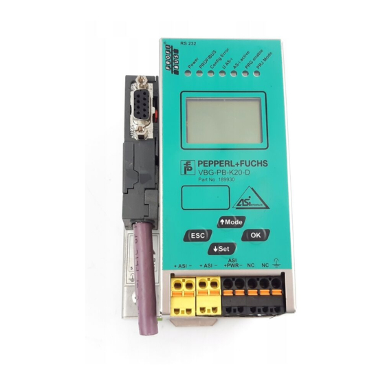
AS-i 3.0 PROFIBUS Gateway in Stainless Steel Electrical connection Electrical connection Overview of terminals, indicators and operating elements 7.1.1 VBG-PB-K20-D-BV 0,2 ... 2,5 mm 0,2 ... 2,5 mm 24 ... 12 Legend: LEDs D-sub connection (PROFIBUS interface) LC display Push-buttons... -
Page 22: Vbg-Pb-K20-D-Ev1, Vbg-Pb-K20-Dmd-Ev1, Vbg-Pb-K20-D-Ev
AS-i 3.0 PROFIBUS Gateway in Stainless Steel Electrical connection 7.1.2 VBG-PB-K20-D-EV1, VBG-PB-K20-DMD-EV1, VBG-PB-K20-D-EV 0,2 ... 2,5 mm 0,2 ... 2,5 mm 24 ... 12 Legend: Ethernet diagnostics port LEDs D-sub connection (PROFIBUS interface) LC display Push-buttons AS-i and power supply terminal... -
Page 23: As-I Bus Connection
AS-i 3.0 PROFIBUS Gateway in Stainless Steel Electrical connection AS-i bus connection Blue Brown Blue Brown AS-i- AS-i+ AS-i- AS-i+ 2-conductor AS-i round cable Yellow ASi ribbon cable (Recommended: flexible power cable H05VV-F2x1,5 per DIN VDE 0281) Information! Electrical work is to be performed only by electrical technicians. -
Page 24: Electrical Connection Vbg-Pb-K20-D-Bv, Vbg-Pb-K20-D-Ev1
AS-i 3.0 PROFIBUS Gateway in Stainless Steel Electrical connection 7.4.1 Electrical connection VBG-PB-K20-D-BV, VBG-PB-K20-D-EV1 +ASI +ASI +PWR NC NC 5 mm max! +ASI – Function ground +ASI – ASI +PWR– (max. 8A) Terminal Signal / Description +AS-i– Connection to AS-i Circuit ASI +PWR–... -
Page 25: Electrical Connection Vbg-Pb-K20-Dmd-Ev1
AS-i 3.0 PROFIBUS Gateway in Stainless Steel Electrical connection 7.4.2 Electrical connection VBG-PB-K20-DMD-EV1 5 mm max! +ASI 1– Function ground ASI 1 +PWR– (max. 8A) +ASI 2– ASI 2 +PWR– (max. 8A) Terminal Signal / Description +ASI 1– Connection to AS-i circuit 1 +ASI 2–... -
Page 26: Electrical Connection Vbg-Pb-K20-D-Ev
AS-i 3.0 PROFIBUS Gateway in Stainless Steel Electrical connection 7.4.3 Electrical connection VBG-PB-K20-D-EV +ASI PWR- +ASI1 +ASI1 +ASI2 24V 0V 5 mm max! +ASI 1– Function ground +ASI 1– +ASI 2– + A SI +PWR– (max. 4A) 24V, 0V Terminal Signal / Description +ASI 1–... -
Page 27: Profibus Interface
AS-i 3.0 PROFIBUS Gateway in Stainless Steel Electrical connection PROFIBUS interface The PROFIBUS interface is designed as a 9-pin D-SUB connector, in accordance with the PROFIBUS standard EN 50 170. It is located at the top left-hand side of the master. -
Page 28: Diagnostics Interface
AS-i 3.0 PROFIBUS Gateway in Stainless Steel Electrical connection Diagnostics interface The service and diagnostics interface (in conjunction with AS-i Control Tools software) is used for communication between the PC and the unit. 7.6.1 VBG-PB-K20-D-EV1, VBG-PB-K20-DMD-EV1, VBG-PB-K20-D-EV The service and diagnostics interface in these devices is as RJ45 female config- ured and it is placed on the front plate, on the left hand side. -
Page 29: Data Not Compatible
AS-i 3.0 PROFIBUS Gateway in Stainless Steel Electrical connection 7.7.1.2 Data not compatible If a card is found whose data are incompatible with the device, the following error message is displayed: CHIPCARD NOT COMPATIBLE 7.7.1.3 Card empty The following message is displayed for an empty card:... - Page 30 AS-i 3.0 PROFIBUS Gateway in Stainless Steel Electrical connection CHIPCARD AND AS-I DATA DIFFERENT CARD->MASTER MASTER->CARD CONTINUE Description CHIP CARD>MASTER: Chip card data are copied to the master MASTER->CHIPCARD: Master data are copied to the chip card NEXT: No change to the data The menu can be exited by pressing the ESC/Service key without changing the data.
-
Page 31: Indicators And Operating Elements
AS-i 3.0 PROFIBUS Gateway in Stainless Steel Electrical connection Indicators and operating elements 7.8.1 LED indicators – master The LED’s on the front panel of the device indicate: Power The master is receiving sufficient power. PROFIBUS LED an: Gateway is allocated to a PROFIBUS Master. -
Page 32: Buttons
AS-i 3.0 PROFIBUS Gateway in Stainless Steel Electrical connection 7.8.2 Buttons The buttons are used for the following: ⇑ Mode/ Switching between configuration mode and protected operating mode, and saving the current AS-i configuration as the nominal configuration. Set/⇓ Selecting the address of and assigning an address to a slave. -
Page 33: Operation In Advanced Display Mode
AS-i 3.0 PROFIBUS Gateway in Stainless Steel Operation in advanced display mode Operation in advanced display mode Information! You will find a description of the display menu in the separate document "Display_Menue". -
Page 34: Advanced Diagnostics For As-I Masters
AS-i 3.0 PROFIBUS Gateway in Stainless Steel Advanced Diagnostics for AS-i Masters Advanced Diagnostics for AS-i Masters The advanced AS-i diagnostics is intended to localize occasionally occurring con- figuration errors and to determine the quality of data transmission on AS-i without using additional diagnostics tools. -
Page 35: Offline Phase For Configuration Errors
AS-i 3.0 PROFIBUS Gateway in Stainless Steel Advanced Diagnostics for AS-i Masters Offline Phase for Configuration Errors The AS-i masters with advanced diagnostics offer the possibility to set them- selves into the offline phase when a configuration error occurs and thus are able to transition the AS-i network into a safe operational state. -
Page 36: Earth/Ground Fault Detector
AS-i 3.0 PROFIBUS Gateway in Stainless Steel Advanced Diagnostics for AS-i Masters 9.4.2 Earth/Ground Fault Detector An Earth/Ground Fault exists when the voltage (Nominal value of =0,5 U .) is outside of the following range: AS-i ≤ U ≤ 90% U... -
Page 37: Functions Of The New Generation Of As-I Gateways
AS-i 3.0 PROFIBUS Gateway in Stainless Steel Advanced Diagnostics for AS-i Masters Functions of the new generation of AS-i Gateways The new generation scores with further optimized diagnostics, several additional functions and even greater operating convenience. Information! A listing of the individual devices and their features can be found in section <New... -
Page 38: Current Can Be Read Directly On The Unit
AS-i 3.0 PROFIBUS Gateway in Stainless Steel Advanced Diagnostics for AS-i Masters or on a sensor line. Earth fault sen. The menu EFLT Ratio shows the asymmetry of the AS-i network, referenced to ground (see sketch). 100% AS-i + 100% AS-i - "... -
Page 39: Self-Resetting Fuses
AS-i 3.0 PROFIBUS Gateway in Stainless Steel Advanced Diagnostics for AS-i Masters " Maximal: 1,3A current: 0,3A " Current: 0,3A Current limiting 3,2A 9.5.5 Self-resetting fuses Main menu || SETUP || CURRENT LIMIT || Thanks to self-resetting fuses in the "1 Gateway, 1 power supply for 2 AS-i cir- cuits"... -
Page 40: Ethernet Diagnostics Interface With Web Server
AS-i 3.0 PROFIBUS Gateway in Stainless Steel Advanced Diagnostics for AS-i Masters AS-i Power AS-i PWR Supply change 9.5.7 Ethernet diagnostics interface with web server These devices allow diagnostics for both the Gateway and the AS-i networks (in- cluding Safety technology) over Ethernet without additional software. AS-i net- work can be thus a part of a remote maintenance concept. -
Page 41: Profibus Dp
AS-i 3.0 PROFIBUS Gateway in Stainless Steel PROFIBUS DP PROFIBUS DP This chapter contains all necessary information to operate the PROFIBUS gate- ways in a PROFIBUS DP network. Information! The respective bits ground fault, overvoltage, noise, double address will only be set if AS-i masters are used, which also support these functions. -
Page 42: 10.1.1.1 Diagnostic Description For Vbg-Pb-K20-D-Bv
AS-i 3.0 PROFIBUS Gateway in Stainless Steel PROFIBUS DP The conditions when to set the ExtDiag bit can be chosen using the user parame- ters or the commands of the command interface. The GSD file includes the following presettings: •... - Page 43 AS-i 3.0 PROFIBUS Gateway in Stainless Steel PROFIBUS DP DP diagnostics - double master PDU byte user byte DP/V1 user – station_status 1 – station_status 2 – station_status 3 – master address – ident high – ident low header type...
-
Page 44: Diagnostic Description For Vbg-Pb-K20-D-Ev1, Vbg-Pb-K20-Dmd-Ev1, Vbg-Pb-K20- D-Ev44
AS-i 3.0 PROFIBUS Gateway in Stainless Steel PROFIBUS DP 10.1.1.2 Diagnostic description for VBG-PB-K20-D-EV1, VBG-PB-K20-DMD-EV1, VBG-PB-K20-D-EV DP diagnostics Byte description station state 1 station state 2 station state 3 Master address ident high ident low Tab. 10-4. The following blocks may be optionally appended to the DP diagnostics. Bytes 1 …... -
Page 45: 10.1.1.3 Parameters
AS-i 3.0 PROFIBUS Gateway in Stainless Steel PROFIBUS DP Delta list Byte description … … delta (56 … 63) Tab. 10-6. Byte description 0x0C header 0xA4 (circuit 1)/0xA5 (circuit 2) type 0x00 slot 0x00 spec LPF (0 ... 7) LPF (8 ... 15) …... - Page 46 AS-i 3.0 PROFIBUS Gateway in Stainless Steel PROFIBUS DP DP parameters - single master PDU byte user byte DP/V1 user default User Byte 1 User Byte 2 User Byte 3 Tab. 10-8. DP parameters - double master PDU byte user byte...
- Page 47 AS-i 3.0 PROFIBUS Gateway in Stainless Steel PROFIBUS DP user byte 2 – default Tab. 10-11. user byte 3 – default Tab. 10-12. LPF: 1: LPF will be transmitted in the diagnostics 0: LPF will not be transmitted 1: Delta list will be transmitted in the diagnostics...
-
Page 48: Configuration Dp/V0 (Cyclic Data)
AS-i 3.0 PROFIBUS Gateway in Stainless Steel PROFIBUS DP If a double master is being used, the User-Diagnosis-Bytes 5 to 30 represent AS-i network 1 and the User-diagnosis bytes 31 to 48 represent AS-i network 2. 10.1.2 Configuration DP/V0 (cyclic data) The configuration of the AS-i/PROFIBUS gateways is made with the GSD file. - Page 49 AS-i 3.0 PROFIBUS Gateway in Stainless Steel PROFIBUS DP Length description 16 bytes digital output (slaves 0 - 31) 20 bytes digital output (slaves 0 - 7B) 24 bytes digital output (slaves 0 - 15B) 28 bytes digital output (slaves 0 - 23B)
-
Page 50: I/O Data
AS-i 3.0 PROFIBUS Gateway in Stainless Steel PROFIBUS DP Length description 24 bytes analog output (slaves 29 - 31) 56 bytes analog output (slaves 25 - 31) 88 bytes analog output (slaves 21 - 31) 120 bytes analog output (slaves 17 - 31) - Page 51 AS-i 3.0 PROFIBUS Gateway in Stainless Steel PROFIBUS DP byte slave 6/6A slave 7/7A slave 8/8A slave 9/9A slave 10/10A slave 11/11A slave 12/12A slave 13/13A slave 14/14A slave 15/15A slave 16/16A slave 17/17A slave 18/18A slave 19/19A slave 20/20A...
- Page 52 AS-i 3.0 PROFIBUS Gateway in Stainless Steel PROFIBUS DP Flags input data output data → ConfigurationMode PeripheryFault → ProtectedMode ConfigurationActive Tab. 10-22. ConfigError: 0 = config ok 1 = config error APF: 0 = AS-i power ok 1 = AS-i power fail...
-
Page 53: 10.1.3.2 As-I 16-Bit Data
AS-i 3.0 PROFIBUS Gateway in Stainless Steel PROFIBUS DP 10.1.3.2 AS-i 16-bit data Information! A-slaves map the data on channels 1 and 2. B-slaves map the data on channels 3 and 4. In addition to the access via the command interfaces, the 16-bit data for or by the slaves with 16-bit value can by exchanged cyclically (profile 7.3., S-7.4, S-6.0, S-... -
Page 54: 10.1.3.4 Safety Control/Status
AS-i 3.0 PROFIBUS Gateway in Stainless Steel PROFIBUS DP Request byte … … request parameter byte 34 Response byte command (mirrored) result response parameter byte 1 … … response parameter byte 34 Tab. 10-24. A command of the command interface will be edited if the toggle bit T changed. - Page 55 AS-i 3.0 PROFIBUS Gateway in Stainless Steel PROFIBUS DP Coding of status bytes Bit [0 ... 3] state or. color description green permanent lighting output on green flashing delay time is running at stop category 1 yellow permanent lighting start-up/restart-disable active...
-
Page 56: Dp/V1
AS-i 3.0 PROFIBUS Gateway in Stainless Steel PROFIBUS DP 10.2 DP/V1 To exchange data between the PROFIBUS master and the AS-i/PROFIBUS gate- way via PROFIBUS DP/V1 only one data block is used - slot 1, index 16. Within this data block a command interface is installed like the one used in the DP tele- gram. -
Page 57: System Startup Using As-I Control Tools
AS-i 3.0 PROFIBUS Gateway in Stainless Steel System startup using AS-i Control Tools System startup using AS-i Control Tools The Windows based software AS-i Control Tools enables an easy and clear con- figuration of the AS-i network. Information! AS-i Control Tools must be installed first! This way, the device driver is copied into the previous designed folder in AS-i Control Tools and should be recognized automatically. - Page 58 AS-i 3.0 PROFIBUS Gateway in Stainless Steel System startup using AS-i Control Tools Select ’Ethernet Diagnostic Interface Stainless Steel Gateways’ and con- firm with ’OK’. If the IP address of the gateway is known, enter it directly. Otherwise, use the button ’Search and Configure…’.
- Page 59 AS-i 3.0 PROFIBUS Gateway in Stainless Steel System startup using AS-i Control Tools Select between TCP/IP Configuration via DHCP, or enter the values manu- ally. Apply the values using the button ’Apply and Activate’. AS-Interface configuration Hinweis! A detailed description of the software, see the help function of the AS-i Control Tools.
-
Page 60: Appendix: Example For Startup On A Siemens S7
Appendix: Example for startup on a Siemens S7 Appendix: Example for startup on a Siemens S7 Information! This example shows the start up of the AS-i 3.0 PROFIBUS Gateway in Stainless Steel a Siemens S7-300 programmable logic controller. The start up VBG-PB-K30-D-S is the same with new range of devices. -
Page 61: Electrical Connection For Profibus Dp
AS-i 3.0 PROFIBUS Gateway in Stainless Steel Appendix: Example for startup on a Siemens S7 Once the AS-i circuit has been configured and parameterized as desired, apply this configuration to the VBG-PB-K30-D-S using the function "QUICK SETUP". The VBG-PB-K30-D-S is now ready to run. - Page 62 AS-i 3.0 PROFIBUS Gateway in Stainless Steel Appendix: Example for startup on a Siemens S7 Clicking on the "Open" field adds the GSD file "VBG-PB-K20-DMD 576 A1745.gsd" to the hardware catalog. Clicking on the "Open" field adds the GSD file "VBG-PB-K20-DMD 576 A1745.gsd"...
- Page 63 AS-i 3.0 PROFIBUS Gateway in Stainless Steel Appendix: Example for startup on a Siemens S7 When adding the CPU module you are prompted for the desired PROFIBUS con- nection. The standard proposed is for the CPU as PROFIBUS DP Master. This can be directly applied.
-
Page 64: Insert As-I 3.0 Profibus Gateway In Stainless Steel
"Properties PROFIBUS" # "Network settings" # "Profile" # "User defined". 12.2.2 Insert AS-i 3.0 PROFIBUS Gateway in Stainless Steel Once the SIMATIC hardware has been added to the hardware configuration and the PROFIBUS configured, you can add the VBG-PB-K30-D-S to the project. - Page 65 AS-i 3.0 PROFIBUS Gateway in Stainless Steel Appendix: Example for startup on a Siemens S7 The VBG-PB-K30-D-S is called "VBG-PB-K30-D-S 485_1746" in the catalog and can now be added to the PROFIBUS branch using drag and drop. Opening the device "VBG-PB-K30-D-S 485_1746" by clicking on the plug sign in the hardware catalog causes a list to appear of the possible PROFIBUS commu- nication modules.
- Page 66 AS-i 3.0 PROFIBUS Gateway in Stainless Steel Appendix: Example for startup on a Siemens S7 In addition to sending the AS-i slave digital data, a communication interface mod- ule can be added. The communication interface is used for sending specific com- mands to the VBG-PB-K30-D-S.
-
Page 67: Configuring As-I 3.0 Profibus Gateway In Stainless Steel In-/Output
AS-i 3.0 PROFIBUS Gateway in Stainless Steel Appendix: Example for startup on a Siemens S7 12.2.3 Configuring AS-i 3.0 PROFIBUS Gateway in Stainless Steel in-/output If the VBG-PB-K30-D-S is added to the PROFIBUS using drag and drop, the Step7 hardware configuration shows the following graphic. - Page 68 AS-i 3.0 PROFIBUS Gateway in Stainless Steel Appendix: Example for startup on a Siemens S7 Drag the selected communication module to the table line for Slot 0. Select the desired communication module from the hardware catalog. Here "16 Byte Digital In/Out (0-31)"...
- Page 69 AS-i 3.0 PROFIBUS Gateway in Stainless Steel Appendix: Example for startup on a Siemens S7 Drag the selected communication module to the table line for slot 1. If desired, you can now place additional modules for the command interface and analog value transmission in the following slots:...
-
Page 70: As-I 3.0 Profibus Gateway In Stainless Steel Parameters
K30-D-S takes place in (out) the CPU address range Input (output) data image byte 0 to 15. 12.2.4 AS-i 3.0 PROFIBUS Gateway in Stainless Steel parameters The VBG-PB-K30-D-S is symbolically represented as a rectangular window con- nected with the PROFIBUS branch. Double-clicking in the upper line of this win- dow [(3) P+F 15] opens the dialog window for the properties of this PROFIBUS slave. - Page 71 AS-i 3.0 PROFIBUS Gateway in Stainless Steel Appendix: Example for startup on a Siemens S7 The diagnostics address entered in this window is used for parameterizing the function module SFC13 (diagnostic request). At this address you can use the standard function SFC13 to read out the PROFIBUS diagnostic data of this DP slave while running.
-
Page 72: 12.2.4.1 General Dp Parameters
AS-i 3.0 PROFIBUS Gateway in Stainless Steel Appendix: Example for startup on a Siemens S7 12.2.4.1 General DP parameters Startup when nominal configuration is not the same as actual configuration: Use this parameter to specify whether the AS-i circuit should be started up even if the AS-i circuit has a different configuration than the stored AS-i configuration. - Page 73 AS-i 3.0 PROFIBUS Gateway in Stainless Steel Appendix: Example for startup on a Siemens S7 List of Peripheral Faults The VBG-PB-K30-D-S saves a list of all AS-i slaves which have triggered a pe- ripheral errors. This list can be sent with the PROFIBUS diagnostic data.
- Page 74 AS-i 3.0 PROFIBUS Gateway in Stainless Steel Appendix: Example for startup on a Siemens S7 Default: Setting of the ExtDiag flag on double address is disabled. Freeze Diagnosis The diagnostic data are continuously updated during runtime. If this is not de- sired, this parameter can be used to disable continuous updating.
- Page 75 AS-i 3.0 PROFIBUS Gateway in Stainless Steel Appendix: Example for startup on a Siemens S7...
-
Page 76: 12.2.4.3 Hex Parameterizing
AS-i 3.0 PROFIBUS Gateway in Stainless Steel Appendix: Example for startup on a Siemens S7 12.2.4.3 Hex parameterizing DPV1_Status Hexadecimal representation of the data resulting from the settings for parameter bytes 0 to 2. User_Prm_Data Hexadecimal representation of the data resulting from the settings for parameter bytes 3 to 37. -
Page 77: Variable Table Vat_Asi_Io
AS-i 3.0 PROFIBUS Gateway in Stainless Steel Appendix: Example for startup on a Siemens S7 OB100 Startup OB. This OB is run once when the CPU starts up. VAT_ASI_IO Variable table, AS-i startup example. 12.2.6 Variable table VAT_ASI_IO In the hardware configuration the 16 bytes of I/O data for the AS-i/DP Gateway are coupled to the input/output byte Address 2 to 17 of the process image. - Page 78 AS-i 3.0 PROFIBUS Gateway in Stainless Steel Appendix: Example for startup on a Siemens S7 In the structure of the 16 byte I/O data field each AS-i slave has a 4-bit data field. This is determined by the address of the AS-i slave within the AS-i circuit.
-
Page 79: As-I Flags Byte 0, Input Bits 7 - 4
AS-i 3.0 PROFIBUS Gateway in Stainless Steel Appendix: Example for startup on a Siemens S7 12.2.6.1 AS-i flags byte 0, input bits 7 - 4 In order to check the current operating status of the AS-i circuit, the AS-i flags re- freshed with each PROFIBUS cycle can be used. - Page 80 AS-i 3.0 PROFIBUS Gateway in Stainless Steel Appendix: Example for startup on a Siemens S7 Bit 6: 0 = no action, 1 = turn on configuration mode of AS-i Master Setting Bit 6 switches the AS-i Master to configuration mode. Then for example the command interface can be used to save an existing AS-i configuration using the controller.
-
Page 81: System Behavior On As-I Config Error
If while running in protected mode a configured AS-i slave fails, an AS-i configura- tion error is generated. The missing slave is shown on the display of the AS-i 3.0 PROFIBUS Gate- way in Stainless Steel. The input flag AS-i Config Error bit 4 in byte 2 is set. - Page 82 AS-i 3.0 PROFIBUS Gateway in Stainless Steel Appendix: Example for startup on a Siemens S7 The diagnostic address, here 1022, refers to the specification in the hardware specification of the S7 with respect to the VBG-PB-K30-D-S.
- Page 83 AS-i 3.0 PROFIBUS Gateway in Stainless Steel Appendix: Example for startup on a Siemens S7 As soon as the AS-i configuration error is cleared, the OB82 is invoked again. In turn the diagnostic address of the VBG-PB-K30-D-S, here 1022, is entered as a parameter and the event is declared as an outgoing event.
- Page 84 AS-i 3.0 PROFIBUS Gateway in Stainless Steel Appendix: Example for startup on a Siemens S7 If for timing reasons an AS-i error must be responded to in a non-interrupt con- trolled way, the message can be turned off using the ExtDiag flag. In this case it is sufficient to check the AS-i flag Config Error in the program sequence.
-
Page 85: Codes Indicated By The Display
AS-i 3.0 PROFIBUS Gateway in Stainless Steel Codes Indicated by the Display Codes Indicated by the Display In the basic state of the configuration mode, the addresses of all detected slaves are displayed in two-second intervals. A blank display indicates that the LDS (List of Detected Slaves) is empty, no slaves were detected. -
Page 86: Codes Indicated By As-I Gateway With Standard Function Range
AS-i 3.0 PROFIBUS Gateway in Stainless Steel Codes Indicated by the Display Checksum error in the data menu. "breakpoint": Control III C program in break point. Error while attempting to exit the configuration mode: A slave with address zero exists. -
Page 87: Glossary
AS-i 3.0 PROFIBUS Gateway in Stainless Steel Glossary Glossary A/B slave An AS-i slave with extended addressing. The address range of an A/B slave ex- tends from 1A to 31A and 1B to 31B. As the master needs the fourth output data bit for switching between A and B address, A/B slaves only have three output data bits maximum. - Page 88 AS-i 3.0 PROFIBUS Gateway in Stainless Steel Glossary I/O code The first digit of the slave profile, which indicates how many in- and outputs the slave has. A 4I/4O slave has for example a “7”, and a slave with 4 digital inputs a "0".
- Page 89 AS-i 3.0 PROFIBUS Gateway in Stainless Steel Glossary ID2 Code, extended ID2 code The ID2 code is set by the slave manufacturer and cannot be changed. The AS-i Association determines the ID2 codes, which are assigned for a particular class of slaves.
- Page 90 AS-i 3.0 PROFIBUS Gateway in Stainless Steel Glossary Offline phase In the offline phase all input and output data is reset. This phase is entered after ⇒ the startup of the master, after a AS-i power fail, and during the transition from ⇒...
- Page 91 AS-i 3.0 PROFIBUS Gateway in Stainless Steel Glossary AS-i 2.0 slaves do not have extended ID1 and ID2 codes. A 2.1 or 3.0 AS-inter- face master enters in this case an “F” for each of the extended ID1 and ID2...
-
Page 92: Reference List
AS-i 3.0 PROFIBUS Gateway in Stainless Steel Reference List Reference List 15.1 Manual: “AS-i 3.0 Command Interface“ This Manual contains a detailed description of the AS-i 3.0 Command Interface.
Need help?
Do you have a question about the AS-I 3.0 PROFIBUS and is the answer not in the manual?
Questions and answers