Sign In
Upload
Manuals
Brands
Pepperl+Fuchs Manuals
Power Supply
HD2-DM-A
Pepperl+Fuchs HD2-DM-A Manuals
Manuals and User Guides for Pepperl+Fuchs HD2-DM-A. We have
3
Pepperl+Fuchs HD2-DM-A manuals available for free PDF download: Manual
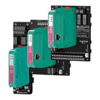
Pepperl+Fuchs HD2-DM-A Manual (203 pages)
Advanced Diagnostics
Brand:
Pepperl+Fuchs
| Category:
Gateway
| Size: 26.01 MB
Table of Contents
Default Mapping Offspec
138
Table of Contents
173
Appendix Signal Level Is too High
175
Signal Level of One or more Devices Is too High
175
Signal Level of One or more Devices Is too Low for the Given Topology
175
Topology Error - Installed Topology Does Not Match Configured Topology
175
Cable Resistance Is too High
175
Bulk Power Supply Failed Fieldbus Power Supply
178
Cable Breakage, Short Cir- Cuit or Terminal Connection Failure
178
Check Bulk Power Supply Install Fieldbus Power Sup
178
Segment Voltage Is Mea- Sured as Zero. Segment Is Unpowered
181
Cause(S)
181
Trunk Breakage between Fieldbus Power Supply and First Device Coupler
181
Not Enough Terminators
181
Trunk Breakage between Device Couplers
181
Too Many Terminators
181
Fieldbus Power Supply Failed
181
Diagnostic Device Is Wrongly or Not Connected to the Segment
181
Check Trunk, Fieldbus Power Supply Terminals and First Device Coupler
181
Check if a Terminator Is
181
Check that the Topology Settings Match the Installa- Tion
191
Check that One Terminator
191
Is Installed on each End of
191
The Trunk Cable, but no
191
More than These Two in Total
191
Check if the Resistance of any Terminal Is too High
191
Check if the Correct Cable
191
Is Installed and the Cable
191
Can be Used for the Topol
191
Check that the Topology
191
Replace Fieldbus Power Supply Module
192
Install Fieldbus Power Sup- Ply
192
Check Cabling and Termi- Nals
193
Check Wiring Connection to the Segment
193
Advertisement
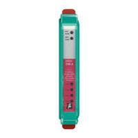
Pepperl+Fuchs HD2-DM-A Manual (108 pages)
ADVANCED DIAGNOSTIC SOLUTIONS
Brand:
Pepperl+Fuchs
| Category:
Control Unit
| Size: 2.53 MB
Table of Contents
Table of Contents
3
1 Explanation of Symbols
6
Safety-Relevant Symbols
6
Informative Symbols
6
2 Introduction
7
Intended Use
9
Maintenance and Service
10
Fault Elimination
10
Disposal
10
3 Product Specifications HD2-DM-A
11
Functional Description
11
Marking
11
Technical Data
12
LED Indication
12
HD2-DM-A Voltage Free Contact Activation
14
Order Information
15
Dimensional Drawings
16
4 Product Specifications DM-AM
17
Functional Description
17
Marking
17
Technical Data
18
Device Component Overview
18
LED Indication and Basic Troubleshooting
19
Order Information
20
Dimensional Drawings
21
5 Application Engineering HD2-DM-A
22
Schematic Diagnostic Structure HD2-DM-A
22
Typical Applications
24
Local Application Structure
24
Remote Application Structure
25
Hardware Installation and Commissioning
26
Device Address Assigning, Mounting and Dismounting
26
Buildup the Diagnostic Bus
28
Com Port Converter Additional Information
29
Software Installation and Commissioning
29
Initial Commissiong of the Diagnostic Project with PACT Ware TM
31
Approved Tags and Tag Values
31
Commissioning of the Diagnostic Project Manually
32
Commissioning the Diagnostic Project Automatically
35
Set Snapshot Archive Location
38
Diagnostic Manager Connection
40
Import Prepared or Saved Diagnostic Project with PACT Ware TM
40
6 Application Engineering DM-AM
42
Schematic Diagnostic Structure DM-AM
42
Mounting and Dismounting
44
How to Use the Test Plug
45
DM-AM Connection Details
47
FDT/DTM Diagnostic Manager Installation and Commissioning
48
Diagnostic Manager Connection
50
7 FDS and OPC Server
51
FDS-Control Center Settings
51
Fieldconnex Diagnostic Server (FDS)
51
FDS-Settings
52
OPC Server
53
OPC-DA Server Name Space
53
OPC-AE Message Data
56
FDS Network Information
57
8 Operation with the Diagnostic Manager
58
Commissioning Wizard
59
Diagnostics
61
System Diagnostics Window
61
Diagnostic Module Diagnostics Window
62
Diagnostic Module Diagnostics Window Overview
62
Alarm Icon Description
63
Diagnostics Filter Function
63
Segment Monitoring
65
Segment Monitoring Data Table Overview
66
Physical Layer Measurement Reports (Snapshot)
68
Snapshot Explorer
69
Detail Parameterization Interfaces
70
Diagnostic Manager User Interface Description
72
Online/Offline Interface Menu Structure Overview
73
HD2-DM-A Operation Modes
74
Field Device Handling
76
PROFIBUS Field Device Measurement Handling
78
Failure and Maintenance Alarm Handling
78
Alarm Hysteresis and Reset
81
Long-Term History
81
History Data Export
82
Fieldbus Oscilloscope Function
83
Oscilloscope Screen Overview
83
Trigger Conditions
85
Firmware Update
87
9 Measured Values / Parameters
88
10 Use Cases and Troubleshooting
94
Use Cases
94
Diagnostics During Installation
94
Troubleshooting
96
Diagnostic Manager/Error Messages
96
11 Installation in Hazardous Areas
100
Safety Instructions
100
Installation of the HD2-DM-A in Conjunction with the Power Hub Within Zone 2 or Class I DIV. 2 or Class I, Zone 2
100
Degree of Protection
101
Installation of the DM-AM Within Zone 2, Class I Division 2 Area or Class I, Zone 2
101
12 List of Referenced Documents
102
Norms
102
Guidelines
102
13 Working with the Stand-Alone Diagnostic Kit
103
Component Overview
104
Connections
105
Commisioning with the Diagnostic Manager
106
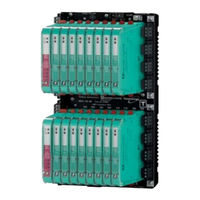
Pepperl+Fuchs HD2-DM-A Manual (28 pages)
Compact Fieldbus Power Hub, Generic Interface
Brand:
Pepperl+Fuchs
| Category:
Power Supply
| Size: 2.43 MB
Table of Contents
Table of Contents
3
1 Safety
5
Validity
5
Symbols Used
5
System Operator and Personnel
5
Pertinent Laws, Standards, Directives, and Further Documentation5
5
Delivery, Transport and Storage
6
Marking
6
Intended Use
6
Mounting and Installation
7
Mounting Instructions for HD2* Modules
7
Zone 2 and DIV. 2
7
Ex IC
8
Housing
8
Repair and Maintenance
8
Disposal
8
2 Specification
9
Overview
9
System Components
10
Motherboard
10
Power Supply Modules HCD2-FBPS
10
Diagnostic Modules
11
Component Identity
12
Dimensional Drawings
12
Technical Data
12
3 Installation and Commissioning
15
Mounting and Dismounting
15
Mounting the Grounding Rail (ACC-MB-HSK)
16
Shielding and Grounding
17
Connection Layout
17
Connections
20
Installation Requirements for Ex IC Installations with MBHC-FB- 8R.HSC.R
20
Segment Termination
21
4 Thermal Dissipation
22
5 Appendix
24
Ordering Information
24
Electromagnetic Compatibility Verification in Accordance with EC Council Legislation Directive 2004/108/EC
24
Referenced Documents
25
Advertisement
Advertisement
Related Products
Pepperl+Fuchs HD2 Series
Pepperl+Fuchs HD2-DM-B
Pepperl+Fuchs HD2-DM-A.RO
Pepperl+Fuchs HCD2-FBPS-1.500
Pepperl+Fuchs HCD2-FBPS-1.23.500
Pepperl+Fuchs HiC2025
Pepperl+Fuchs SMART HiC2025A
Pepperl+Fuchs HiD2024
Pepperl+Fuchs HiD2022 Series
Pepperl+Fuchs HiD2025
Pepperl+Fuchs Categories
Accessories
Security Sensors
Industrial Equipment
Control Unit
Switch
More Pepperl+Fuchs Manuals
Login
Sign In
OR
Sign in with Facebook
Sign in with Google
Upload manual
Upload from disk
Upload from URL