Table of Contents
Advertisement
Advertisement
Table of Contents

Subscribe to Our Youtube Channel
Related Manuals for Pepperl+Fuchs VBG-ENXK20-DMD-EV


Summary of Contents for Pepperl+Fuchs VBG-ENXK20-DMD-EV
- Page 1 ACTORY UTOMATION MANUAL 3.0 E /IP+ THER TCP G ODBUS ATEWAY...
- Page 2 AS-i 3.0 EtherNet/IP+ Modbus TCP Gateway With regard to the supply of products, the current issue of the following document is applicable: The General Terms of Delivery for Products and Services of the Electrical Industry, published by the Central Association of the Electrical Industry (Zentralverband Elektrotechnik und Elektroindustrie (ZVEI) e.V.) in its most recent version as well as the supplementary clause: "Expanded reservation of proprietorship".
-
Page 3: Table Of Contents
AS-i 3.0 EtherNet/IP+Modbus TCP Gateway Table of contents Table of contents AS-i 3.0 EtherNet/IP+ Modbus TCP Gateway Table of contents Introduction...................7 Declaration of conformity ..............8 Declaration of conformity................8 Safety .....................9 Intended use ..................... 9 General safety information................9 3.2.1 Disposal..........................9 General .................... - Page 4 AS-i 3.0 EtherNet/IP+Modbus TCP Gateway Table of contents 6.7.1 Faulty slaves ........................21 6.7.2 Error display (last error)....................21 6.7.3 Replacing the chip card ....................22 6.7.4 Local parameter setting of AS-i/Gateways..............23 Electrical connection................24 Overview of terminals, indicators and operating elements....... 24 7.1.1 VBG-ENX-K20-D, VBG-ENX-K20-DMD, VBG-ENX-K20-DMD-EV........24 AS-i bus connection ..................
- Page 5 AS-i 3.0 EtherNet/IP+Modbus TCP Gateway Table of contents 10.3 Quality of Service Object................43 10.4 Assembly Object .................... 45 10.5 AS-i Master Object ..................48 10.6 AS-i slave Object.................... 51 10.7 I/O Data Object ....................52 10.8 Advanced Diagnostics Object ..............55 10.9 Short Command Interface Object ..............
- Page 6 AS-i 3.0 EtherNet/IP+Modbus TCP Gateway Table of contents System startup using AS-i Control Tools.........88 Appendix, Examples................91 15.1 Commissioning with RSLogix5000 V20 or higher ........91 15.2 The first commissioning with CompactLogix ........... 101 15.2.1 Working with sample files...................105 Codes indicated by the display ............106 Glossary.....................108 Reference List ...................113 18.1...
-
Page 7: Introduction
Introduction Introduction Congratulations You have chosen a device manufactured by Pepperl+Fuchs. Pepperl+Fuchs de- velops, produces and distributes electronic sensors and interface modules for the market of automation technology on a worldwide scale. Before installing this equipment and put into operation, read this manual carefully. -
Page 8: Declaration Of Conformity
This product was developed and manufactured under observance of the applica- ble European standards and guidelines. Information! A Declaration of Conformity can be requested from the manufacturer. The product manufacturer, Pepperl+Fuchs GmbH, D-68307 Mannheim, has a certified quality assurance system that conforms to ISO 9001. -
Page 9: Safety
AS-i 3.0 EtherNet/IP+Modbus TCP Gateway Safety Safety Intended use Warning! This symbol warns of a possible danger. The protection of operating personnel and the system against possible danger is not guaranteed if the control interface unit is not operated in accordance to its intended use. General safety information Warning! Safety and correct functioning of the device cannot be guaranteed if any operation... -
Page 10: General
AS-i 3.0 EtherNet/IP+Modbus TCP Gateway General General Product information This system manual applies to the following Pepperl+Fuchs GmbH equipment: 2 AS-i net- Ethernet VBG-ENX- EtherNet/IP + yes, max. 4A/ optio Gateway IP20 works, 2 AS-i Feldbus + K20-DMD-EV ModbusTCP AS-i network... -
Page 11: New Generation Of As-I Gateways With Ethernet Diagnostics Interface
AS-i 3.0 EtherNet/IP+Modbus TCP Gateway General New Generation of AS-i Gateways with ethernet diagnostics interface The plus points of the new Gateway generation at a glance: • Gateways now programmable in C • Ethernet diagnostics interface for remote diagnostics • Integrated web server: diagnostics for the Gateways and the AS-i circuits over Ethernet possible with no additional software •... -
Page 12: Specifications
AS-i 3.0 EtherNet/IP+Modbus TCP Gateway Specifications Specifications Technical data The technical data are placed in the data sheet. Please view the current version on the web page: http://www.pepperl-fuchs.de. -
Page 13: Installation
AS-i 3.0 EtherNet/IP+Modbus TCP Gateway Installation Installation Dimensions Warning! Cover the top of the gateway when doing any drilling work above the unit. No particles, especially metal chips, should be allowed to enter the housing, since this could cause a short circuit. -
Page 14: Installing In The Control Cabinet
AS-i 3.0 EtherNet/IP+Modbus TCP Gateway Installation Installing in the control cabinet The AS-i/Gateway is installed in the control cabinet on 35mm DIN rails per DIN EN 50 022. Information! The enclosure of the AS-i/Gateway is made of stainless steel. The unit is also suitable for exposed wall mounting. -
Page 15: Commissioning
AS-i 3.0 EtherNet/IP+Modbus TCP Gateway Installation Commissioning 6.5.1 Switching to advanced display mode classical display advanced display mode 1.12A ETHERNET QUICK SETUP SLAVE ADR TOOL UNKNOWN SLAVE SLAVE TEST TOOL menu structure see additional page The device handels multiple protocols! Please select one of them during the initial operation. -
Page 16: Displaying Of Ethernet Properties
AS-i 3.0 EtherNet/IP+Modbus TCP Gateway Installation 6.5.2.1 Displaying of Ethernet properties ETHERNET TCP/IP MODBUS ETHERNET LINK: 100 BASE-TX FDX MAC ID: 00-16-77-00- 2E-C3 ETHERNET TCP/IP ACTUAL VALUES MODBUS CONFIGURATION ACTUAL VALUES IP ADDRESS 192. 168. 000.254 NET MASK 255. 255. 255. 0 GATEWAY 0 .0 .0 .0 6.5.2.2... -
Page 17: Setting Of Watchdog Time
AS-i 3.0 EtherNet/IP+Modbus TCP Gateway Installation 6.5.2.3 Setting of watchdog time ETHERNET TCP/IP MODBUS WATCHDOG TIME in 10ms steps 000 = disable " 6.5.3 Select EtherNet/IP ETHERNET QUICK SETUP SLAVE ADR. TOOL ↓ SLAVE TEST TOOL MODBUS TCP MODBUS TCP X ETHERNET/IP X ETHERNET/IP ↓... -
Page 18: Select Command Interface Mode
AS-i 3.0 EtherNet/IP+Modbus TCP Gateway Installation 6.5.3.1 Select command interface mode MODBUS TCP MAILBOX MODE 38 Byte: ETHERNET/IP X Enchanced mailbox length for current device re- vision TCP OBJECT 36 Byte: ↓ Compatibility mode for older devices ETHERNET OBJECT MAILBOX MODE MAILBOX MODE MAILBOX MODE 36 BYTE... -
Page 19: Connecting As-I Slaves
AS-i 3.0 EtherNet/IP+Modbus TCP Gateway Installation 6.5.4 Connecting AS-i Slaves power power 1. 1 config error config error U AS-i U AS-i AS-i active AS-i active prg enable prg enable prj mode prj mode 0.5s AS-i AS-i 1. 5 AS-i Slave 1 AS-i Slave 1... -
Page 20: Quick Setup
AS-i 3.0 EtherNet/IP+Modbus TCP Gateway Installation Quick setup config error 1. 5 STORE AS-I CONFIGURATION STORE +PRJ MODE 1xOK ↓ 2x ESC ETHERNET QUICK SETUP SETUP IO + PARAM. TEST CONFIGURATION OK WARNING: OUTPUTS MAY BE HOST ERROR RESET NO CONNECTION ↓... -
Page 21: Error Tracing
AS-i 3.0 EtherNet/IP+Modbus TCP Gateway Installation Error tracing 6.7.1 Faulty slaves power config error U AS-i AS-i active prg enable MISSING SLAVE prj mode AS-i AS-i Slave 1 1.24 AS-i Slave 5 MISSING SLAVE AS-i Slave 24 6.7.2 Error display (last error) power power config error... -
Page 22: Replacing The Chip Card
AS-i 3.0 EtherNet/IP+Modbus TCP Gateway Installation 6.7.3 Replacing the chip card Always turn off power before inserting or removing the card! -
Page 23: Local Parameter Setting Of As-I/Gateways
AS-i 3.0 EtherNet/IP+Modbus TCP Gateway Installation 6.7.4 Local parameter setting of AS-i/Gateways... -
Page 24: Electrical Connection
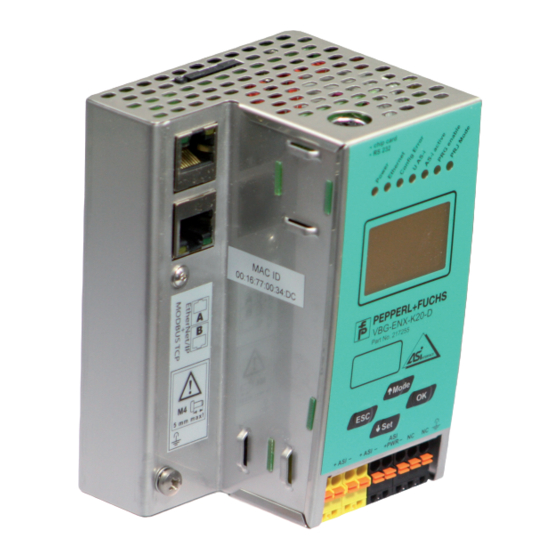
AS-i 3.0 EtherNet/IP+Modbus TCP Gateway Electrical connection Electrical connection Overview of terminals, indicators and operating elements 7.1.1 VBG-ENX-K20-D, VBG-ENX-K20-DMD, VBG-ENX-K20-DMD-EV 0,2 ... 2,5 mm 0,2 ... 2,5 mm 24 ... 12 Legend: LEDs Ethernet interface LC display Buttons Terminals: Supply voltage and AS-i circuit Chip card RS232 diagnostics port Only together with AS-i Control Tools... -
Page 25: As-I Bus Connection
AS-i 3.0 EtherNet/IP+Modbus TCP Gateway Electrical connection AS-i bus connection Blue Brown Blue Brown AS-i- AS-i+ AS-i- AS-i+ 2-conductor AS-i round cable Yellow ASi ribbon cable (Recommended: flexible power cable H05VV-F2x1,5 per DIN VDE 0281) Information! Electrical work is to be performed only by electrical technicians. Information about the device types Information! A listing of the individual devices and their features can be found in section <Product... -
Page 26: Electrical Connection Vbg-Enx-K20-D
AS-i 3.0 EtherNet/IP+Modbus TCP Gateway Electrical connection 7.4.1 Electrical connection VBG-ENX-K20-D +ASI +ASI +PWR NC NC 5 mm max! +ASI – Function ground +ASI – ASI +PWR– (max. 8A) Terminal Signal / Description +AS-i– Connection to AS-i Circuit ASI +PWR– Supply voltage for AS-i Circuit (max. -
Page 27: Electrical Connection Vbg-Enx-K20-Dmd
AS-i 3.0 EtherNet/IP+Modbus TCP Gateway Electrical connection 7.4.2 Electrical connection VBG-ENX-K20-DMD 5 mm max! +ASI 1– Function ground ASI 1 +PWR– (max. 8A) +ASI 2– ASI 2 +PWR– (max. 8A) Terminal Signal / Description +ASI 1– Connection to AS-i circuit 1 +ASI 2–... -
Page 28: Electrical Connection Vbg-Enx-K20-Dmd-Ev
AS-i 3.0 EtherNet/IP+Modbus TCP Gateway Electrical connection 7.4.3 Electrical connection VBG-ENX-K20-DMD-EV +ASI PWR- +ASI1 +ASI1 +ASI2 24V 0V 5 mm max! +ASI 1– Function ground +ASI 1– +ASI 2– + A SI +PWR– (max. 4A) 24V, 0V Terminal Signal / Description +ASI 1–... -
Page 29: Ethernet Interface
AS-i 3.0 EtherNet/IP+Modbus TCP Gateway Electrical connection Ethernet interface The ethernet interface consists of two RJ-45 sockets. It is placed on the left hous- ing side (see section <Overview of terminals, indicators and operating ele- ments>). The ethernet interface is driven according to the IEEE 802.3 Diagnostics interface The service and diagnostics interface (in conjunction with AS-i Control Tools software) is used for communication between the PC and the unit. -
Page 30: Indicators And Operating Elements
AS-i 3.0 EtherNet/IP+Modbus TCP Gateway Electrical connection Indicators and operating elements 7.8.1 LED indicators – master The LED’s on the front panel of the device indicate: Power The master is receiving sufficient power. (the bi-color LED indicates the state of the ethernet port) LED red: no valid ENIP- or CIP connection. -
Page 31: Buttons
AS-i 3.0 EtherNet/IP+Modbus TCP Gateway Electrical connection 7.8.2 Buttons The buttons are used for the following: ⇑ Mode/ Switching between configuration mode and protected operating mode, and saving the current AS-i configuration as the nominal configuration. Set/⇓ Selecting the address of and assigning an address to a slave. OK, ESC Changing to the advanced display mode. -
Page 32: Operation In Advanced Display Mode
AS-i 3.0 EtherNet/IP+Modbus TCP Gateway Operation in advanced display mode Operation in advanced display mode Information! You will find a description of the display menu in the separate document "Display_Menue". -
Page 33: Advanced Diagnostics For As-I Masters
AS-i 3.0 EtherNet/IP+Modbus TCP Gateway Advanced Diagnostics for AS-i Masters Advanced Diagnostics for AS-i Masters The advanced AS-i diagnostics is intended to localize occasionally occurring con- figuration errors and to determine the quality of data transmission on AS-i without using additional diagnostics tools. AS-i Control Tools, a MS-Windows software designed to simplify AS-i installation and used to program AS-i Control, enables operation of the advanced diagnostics functions (LCS, error counters, and LOS). -
Page 34: Offline Phase For Configuration Errors
AS-i 3.0 EtherNet/IP+Modbus TCP Gateway Advanced Diagnostics for AS-i Masters Offline Phase for Configuration Errors The AS-i masters with advanced diagnostics offer the possibility to set them- selves into the offline phase when a configuration error occurs and thus are able to transition the AS-i network into a safe operational state. -
Page 35: Earth/Ground Fault Detector
AS-i 3.0 EtherNet/IP+Modbus TCP Gateway Advanced Diagnostics for AS-i Masters 9.4.2 Earth/Ground Fault Detector An Earth/Ground Fault exists when the voltage (Nominal value of =0,5 U .) is outside of the following range: AS-i ≤ U ≤ 90% U 10% U AS-i AS-i This error substantially limits the noise immunity of the AS-i communication. -
Page 36: Functions Of The New Generation Of As-I Gateways
AS-i 3.0 EtherNet/IP+Modbus TCP Gateway Advanced Diagnostics for AS-i Masters Functions of the new generation of AS-i Gateways The new generation scores with further optimized diagnostics, several additional functions and even greater operating convenience. Information! A listing of the individual devices and their features can be found in section <New Generation of AS-i Gateways with ethernet diagnostics interface>. -
Page 37: Current Can Be Read Directly On The Unit
AS-i 3.0 EtherNet/IP+Modbus TCP Gateway Advanced Diagnostics for AS-i Masters or on a sensor line. Earth fault sen. The menu EFLT Ratio shows the asymmetry of the AS-i network, referenced to ground (see sketch). 100% AS-i + 100% AS-i - EFLT Ratio: AS-i+ 2% AS-i DC Voltage: 1... -
Page 38: Self-Resetting Fuses
AS-i 3.0 EtherNet/IP+Modbus TCP Gateway Advanced Diagnostics for AS-i Masters Maximal: 1,3A current: " 0,3A Current: 0,3A Current limiting " 3,2A 9.5.5 Self-resetting fuses Main menu || SETUP || CURRENT LIMIT || Thanks to self-resetting fuses in the "1 Gateway, 1 power supply for 2 AS-i cir- cuits"... -
Page 39: Ethernet Diagnostics Interface With Web Server
AS-i 3.0 EtherNet/IP+Modbus TCP Gateway Advanced Diagnostics for AS-i Masters AS-i Power AS-i PWR Supply change 9.5.7 Ethernet diagnostics interface with web server These devices allow diagnostics for both the Gateway and the AS-i networks (in- cluding Safety technology) over Ethernet without additional software. AS-i net- work can be thus a part of a remote maintenance concept. -
Page 40: Ethernet/Ip Interface
AS-i 3.0 EtherNet/IP+Modbus TCP Gateway EtherNet/IP interface EtherNet/IP interface Objekt modelling The attributes of bus participants are mapped into objects in the CIP family (De- viceNet, ControlNet and EtherNet/IP) bus systems. In addition to for all EtherNet/IP devices common objects, there are other objects in the AS-i gateways to access the data of the AS-i network: •... -
Page 41: Identity Object
AS-i 3.0 EtherNet/IP+Modbus TCP Gateway EtherNet/IP interface 10.1 Identity object class code: 1 (0x01) number of instanzes: 1 instance attributes Attribute ID Access Rule Name Value vendor device type product code e. g.: "2386" (double master) e. g.: "2385" (single master) revision status see overwiev listed below... -
Page 42: Device Level Ring Object
AS-i 3.0 EtherNet/IP+Modbus TCP Gateway EtherNet/IP interface 10.2 Device Level Ring Object Class Code: 71 (0x47) number of instanzes: 1 instance attributes Attribute ID Access Rule Name Value 1 (0x01) network topo- 0 (linear), 1 (ring) logy 2 (0x02) network status 0 (normal), 1 (ring fault) 10 (0x0E) active supervi-... -
Page 43: Quality Of Service Object
AS-i 3.0 EtherNet/IP+Modbus TCP Gateway EtherNet/IP interface 10.3 Quality of Service Object Class Code: 72 (0x48) number of instanzes: 1 instance attributes Attribute ID Access Rule Name Value 1 (0x01) get/set 802.1q tag 0 (disabled), 1 (enabled) enable 4 (0x04) get/set dscp urgent dscp after rfc 3168 for cip class 0/1... - Page 44 AS-i 3.0 EtherNet/IP+Modbus TCP Gateway EtherNet/IP interface Mapping of the SDCP and 802.1D priorities to the queues is as follows: Switch queue DSCP 802.1D priority 4 (highest priority) 46, DSCP Urgent, DSCP Scheduled, 4, 5, 6 DSCP High 24, DSCP Low, DSCP Explicit 1 (lowest priority) other values Tab.
-
Page 45: Assembly Object
AS-i 3.0 EtherNet/IP+Modbus TCP Gateway EtherNet/IP interface 10.4 Assembly Object class code 4 (0x04) number of instances: 86 The Assembly Object bandles data from the application objects. The Assembly Object Instances consist of (in case of a double master): • A-slaves and/or single slaves from circuit 1 •... - Page 46 AS-i 3.0 EtherNet/IP+Modbus TCP Gateway EtherNet/IP interface 16-bit data of slaves 29 … 31 n+20 Slave 29 ch3 high byte n+21 Slave 29 ch3 low byte n+22 Slave 29 ch4 high byte n+23 Slave 29 ch4 low byte Tab. 10-10. Instances 100 (0x64)…135 (0x87) can only be read, while instances 136 (0x88) …171 (0xAB) can be read and written.
- Page 47 AS-i 3.0 EtherNet/IP+Modbus TCP Gateway EtherNet/IP interface Assembly Instance Data Item input output size digital analog command inter- (byte) face 100 (0x64) 136 (0x88) 16 101 (0x65) 137 (0x89) 28 short 102 (0x66) 138 (0x8A) 54 long 103 (0x67) 139 (0x8B) 40 AS-i circuit 1, AS-i circuit 1, 104 (0x68)
-
Page 48: As-I Master Object
AS-i 3.0 EtherNet/IP+Modbus TCP Gateway EtherNet/IP interface 10.5 AS-i Master Object class code: 100 (0x64) 1 instance for each AS-i circuit attribute access rule name devicenet data default data type value 100 (0x64) ec-flags UINT (16-bit) 101 (0x65) get/set hi-flags USINT 102 (0x66) get/set... - Page 49 AS-i 3.0 EtherNet/IP+Modbus TCP Gateway EtherNet/IP interface CA (configuration_active): The configuration-mode is active AAv (Auto_Address_Available): Automatic programming is possible 0: Auto-address is possible 1: Auto-address is not possible AAs (Auto_Address_Assign): Automatic programming is allowed S0 (LDS.0): There is an AS-i slave with address ’0’ Cok (config_ok): Configuration error: 0: no error 1: error...
- Page 50 AS-i 3.0 EtherNet/IP+Modbus TCP Gateway EtherNet/IP interface Store actual parameter/store actual configuration/lock push-buttons True: proceed the action Change slave address (16-bit) Byte – source address – target address Tab. 10-16. Meaning of the bit B B = 0: Single AS-i Slave or A-slave B = 1: B-slave...
-
Page 51: As-I Slave Object
AS-i 3.0 EtherNet/IP+Modbus TCP Gateway EtherNet/IP interface 10.6 AS-i slave Object class code: 101 (0x65) 64 instances for each AS-i circuit, 1 for each AS-i slave instance ID AS-i slave 1 (0x01) slave 0, circuit 1 2 (0x02) slave 1A, circuit 1 …... -
Page 52: I/O Data Object
AS-i 3.0 EtherNet/IP+Modbus TCP Gateway EtherNet/IP interface 10.7 I/O Data Object class code: 102 (0x66) Input and output data 1 instance for each AS-i circuit Instance 1 equates to AS-i circuit 1 Instance 2 equates to AS-i circuit 2 attribute access rule name devicenet data type default data value... - Page 53 AS-i 3.0 EtherNet/IP+Modbus TCP Gateway EtherNet/IP interface Input and Output Data Image Byte flags slave 1/1A slave 2/2A slave 3/3A slave 4/4A slave 5/5A slave 6/6A slave 7/7A slave 8/8A slave 9/9A slave 10/10A slave 11/11A slave 12/12A slave 13/13A slave 14/14A slave 15/15A slave 16/16A...
- Page 54 AS-i 3.0 EtherNet/IP+Modbus TCP Gateway EtherNet/IP interface Flags Input data Output data ConfigError Off-line LOS-master-bit → ConfigurationMode PeripheryFault → ProtectedMode ConfigurationActive Tab. 10-23. ConfigError: 0=ConfigOK 1=ConfigError APF: 0=AS-i-Power OK 1=AS-i-Power Fail PeripheryFault: 0=PeripheryOK 1=PeripheryFault ConfigurationActive: 0=ProtectedOperationMode 1=ProjectingMode Off-Line: 0=On-Line 1=Off-Line LOS-master-bit 0=Off-Line by ConfigError 1=Off-Line by ConfigError...
-
Page 55: Advanced Diagnostics Object
AS-i 3.0 EtherNet/IP+Modbus TCP Gateway EtherNet/IP interface 10.8 Advanced Diagnostics Object class code: 103 (0x67) 1 instance for each AS-i circuit Instance 1 equates to AS-i circuit 1 Instance 2 equates to AS-i circuit 2 attribute access name devicenet default rule data type data value... -
Page 56: Short Command Interface Object
AS-i 3.0 EtherNet/IP+Modbus TCP Gateway EtherNet/IP interface 10.9 Short Command Interface Object class code: 104 (0x68) 1 instance attribute access name devicenet default rule data type data value 100 (0x64) get/set content ARRAY[12] of USINT command toggle-bit and AS-i circuit [2 …... -
Page 57: Safety Control/Status
AS-i 3.0 EtherNet/IP+Modbus TCP Gateway EtherNet/IP interface 10.11 Safety Control/Status 10.11.1 External Monitor 10.11.1.1 Safety Control Status external Monitor class code: 107 (0x6B) 1 instance per AS-i circuit attribute access name devicenet default rule data type data value 100 (0x64) slave 1: ARRAY [8] of USINT safety status release circuit 1 [0]... - Page 58 AS-i 3.0 EtherNet/IP+Modbus TCP Gateway EtherNet/IP interface Coding of status bytes per OSSD Bit [0 ... 3] State or. color green permanent lighting green flashing yellow permanent lighting yellow flashing red permanent lighting red flashing grey or off reserved Bit [6] status or color no device flashing yellow at least one device flashing yellow...
-
Page 59: The Modbus Address Table
AS-i 3.0 EtherNet/IP+Modbus TCP Gateway The Modbus Address Table The Modbus Address Table Cyclic data exchange similar to the Momentum Ethernet Adapter AS-i circuit 1: Input Data Image IDI contact read access refer- ence bit value „bit“ 1 - 16 F4 F5 F10 F11 F12 F13 F14 F15 F16 17 - 32... - Page 60 AS-i 3.0 EtherNet/IP+Modbus TCP Gateway The Modbus Address Table Cyclic data exchange similar to the Momentum Ethernet Adapter AS-i circuit 2: Input Data Image IDI contact read access reference bit value „Bit“ 273 - 288 F1 F2 F7 F8 F10 F11 F12 F13 F14 F15 F16 289 - 304 slave 0/0A slave 1/1A slave 2/2A...
- Page 61 AS-i 3.0 EtherNet/IP+Modbus TCP Gateway The Modbus Address Table Cyclic data exchange similar to the Momentum Ethernet Adapter AS-i circuit 1: Output Data Image ODI contact write access reference bit value „Bit“ 1 - 16 F8 F9 F10 F11 F12 F13 F14 F15 F16 17 - 32 slave 0/0A slave 1/1A...
- Page 62 AS-i 3.0 EtherNet/IP+Modbus TCP Gateway The Modbus Address Table Cyclic data exchange similar to the Momentum Ethernet Adapter AS-i circuit 2: Output Data Image ODI contact write access reference bit value „bit“ 273 - 288 F1 F7 F8 F9 F10 F11 F12 F13 F14 F15 F16 289 - 304 slave 0/0A slave 1/1A slave 2/2A...
- Page 63 AS-i 3.0 EtherNet/IP+Modbus TCP Gateway The Modbus Address Table The bits within the words of this block are arranged appropriate for the BLKM (Block Move) function in Modicon's 984 Ladder Language (as proposed in the Open Modbus Specification, Release 1.0). The bits are numbered from most signicant bit to least signicant bit: Reference 1 Flag...
- Page 64 AS-i 3.0 EtherNet/IP+Modbus TCP Gateway The Modbus Address Table Data_Exchange_Active: If this output is set, no data transmisson between the AS-i/Gateway and the AS-i slaves is possible. 0: Data exchange is active 1: Data exchange is not active Off-line: This output sets the master into the off-line phase Auto_Address_Enable: This output blocks the automatic slave-address program- ming.
- Page 65 AS-i 3.0 EtherNet/IP+Modbus TCP Gateway The Modbus Address Table Reference 2 bit value write read 8000 ODI slave 0, D0 IDI slave 0, D0 4000 ODI slave 0, D1 IDI slave 0, D1 2000 ODI slave 0, D2 IDI slave 0, D2 1000 ODI slave 0, D3 IDI slave 0, D3...
- Page 66 AS-i 3.0 EtherNet/IP+Modbus TCP Gateway The Modbus Address Table Device-relevant references 4x referece access data 2049 ... 2064 AS-i/ENIP Gateway 2065 ... 2072 device version 2073 ... 2080 firmware feature (without hi-flags) 2081 ... 2084 firmware data code 2085 Front_Panel_Operation (0 enabled, else disabled) 2086 return value of most recently called Execution Control function:...
- Page 67 AS-i 3.0 EtherNet/IP+Modbus TCP Gateway The Modbus Address Table Device-relevant references (similar to the Momentum Ethernet Adapter) 4x reference access data 2087 default value for watchdog timeout in 10 ms units range 1 to 999 (this value overwrites the value written in the reference 61441) 61441 timeout in 10 msec units default 100 (≡...
- Page 68 AS-i 3.0 EtherNet/IP+Modbus TCP Gateway The Modbus Address Table 4x reference 4225 Bit value execution control flags Config_OK! LDS.0 Auto_Address_Assign Auto_Address_Available! Configuration_Active Normal_Operation_Active! APF/not APO Offline_Ready Periphery_OK! 1000 Earth Fault 2000 Overvoltage 4000 Noise 8000 Duplicate Address Tab. 11-43.
- Page 69 AS-i 3.0 EtherNet/IP+Modbus TCP Gateway The Modbus Address Table Config_OK!: Configuration error 0: error 1: no error LDS.0: An AS-i slave with address zero is existing Auto_Address_Assign: Automatic programming is allowed Auto_Address_Available!: Automatic programming is possible 0: Auto-address is not possible 1: Auto-address is possible Configuration_Active: The configuration-mode is active Normal_Operation_Active!: The normal operation mode is active...
- Page 70 AS-i 3.0 EtherNet/IP+Modbus TCP Gateway The Modbus Address Table Off-line: This output sets the master into the off-line phase. Auto_Address_Enable!: This output blocks automatic slave-address program- ming. 0: Auto-address is disabled 1: Auto-address is enabled 4x reference 4145 … 4208 Bit mask data 000F...
-
Page 71: Safety Control/Status
AS-i 3.0 EtherNet/IP+Modbus TCP Gateway The Modbus Address Table 11.1 Safety Control/Status 11.1.1 External monitor, AS-i circuit 1/2 Safety status external monitor (data for read access) access data read access reference bit value „bit“ 5641 r / – slave 1: OSSD 1 slave 1: OSSD 2 …... - Page 72 AS-i 3.0 EtherNet/IP+Modbus TCP Gateway The Modbus Address Table Safety status external monitor (data for write access) data write access refer- ence bit value „bit“ 10 11 12 13 5889 r / reserved Slave 1 Slave 1 Slave 1 Slave 1 2.Y2 2.Y1 1.Y2...
-
Page 73: As-I Circuit 1 Data
AS-i 3.0 EtherNet/IP+Modbus TCP Gateway The Modbus Address Table 11.2 AS-i circuit 1 data 11.2.1 Permanent configuration data AS-i circuit 1 permanent configuration data 4x reference access data 4385 ... 4400 permanent parameter (PP) 4401 ... 4464 permanent configuration data (PCD) 4465 ... -
Page 74: Function Invocation
AS-i 3.0 EtherNet/IP+Modbus TCP Gateway The Modbus Address Table 11.2.3 Function invocation AS-i circuit 1 function invocation 4x reference access data 4865 function: opcode 1: Set_Operation_Mode 2: Change_Slave_Address 3: Store_Actual_Parameters 4: Store_Actual_Configuration 5: Execute_Command 6: Send_Parameter 4865 function: result 0: success 32769: failure 32770: slave with 1st addr not detected 32771: slave with zero addr detected... -
Page 75: As-I Circuit 1 Analog Data
AS-i 3.0 EtherNet/IP+Modbus TCP Gateway The Modbus Address Table Information! B addresses are located behind A addresses. Addresses 0 … 31 correspond to 0A … 31A, addresses 32 … 64 correspond to 0B … 31B. 11.3 AS-i circuit 1 analog data 11.3.1 16 bit output data of AS-i slaves according to slave profile 7.3 or 7.4 AS-i circuit 1... -
Page 76: As-I Circuit 2 Data
AS-i 3.0 EtherNet/IP+Modbus TCP Gateway The Modbus Address Table 11.4 AS-i circuit 2 data 11.4.1 Process data and actual configuration data AS-i circuit 2 process data and actual configuration data 4x reference access data 8193 ... 8208 input data image IDI 8209 ... -
Page 77: Function Invocation
AS-i 3.0 EtherNet/IP+Modbus TCP Gateway The Modbus Address Table 11.4.4 Function invocation AS-i circuit 2 Function invocation 4x reference access data 8961 function: opcode 1: Set_Operation_Mode 2: Change_Slave_Address 3: Store_Actual_Parameters 4: Store_Actual_Configuration 5: Execute_Command 6: Send_Parameter 8961 function: result 0: success 32769: failure 32770: slave with 1st addr not detected 32771: slave with zero addr detected... -
Page 78: As-I Circuit 2 Analog Data
AS-i 3.0 EtherNet/IP+Modbus TCP Gateway The Modbus Address Table 11.5 AS-i circuit 2 analog data 11.5.1 16 bit output data of AS-i slaves according to slave profile 7.3 or 7.4 AS-i circuit 2 16 bit output data of as-i slaves according to slave profile 7.3 or 7.4 data word reference... -
Page 79: Operation Via Ethernet Ip (Modbus/Tcp)
AS-i 3.0 EtherNet/IP+Modbus TCP Gateway Operation via Ethernet IP (Modbus/TCP) Operation via Ethernet IP (Modbus/TCP) The AS-i/Gateway acts as a 1 or 2 complete Master for the AS-i and as a 256 bit digital I/O module for Ethernet. All possibilities offered by AS-i can be used via Ethernet TCP/IP. -
Page 80: Ethernet Tcp/Ip Functions
AS-i 3.0 EtherNet/IP+Modbus TCP Gateway Operation via Ethernet IP (Modbus/TCP) Information! Checksum fields are not needed, because the TCP/IP and link layer (eg. Ethernet) instad are used to verfiy accurate delivery of the packet. Example transaction: Read 1 register at offset 4 from UI 9. Return value is 5 request response 12.2... -
Page 81: Function 23 (17Hex): "Read/Write Multiple Registers
AS-i 3.0 EtherNet/IP+Modbus TCP Gateway Operation via Ethernet IP (Modbus/TCP) 12.2.3 Function 23 (17hex): "Read/Write multiple registers" This function allows to read the value of read/write-registers and the setting of several read/write-registers: request: high high high … high high response: …... - Page 82 AS-i 3.0 EtherNet/IP+Modbus TCP Gateway Operation via Ethernet IP (Modbus/TCP) 03 46 60 00 01 ⇒ 128 02 request: read 1 Register at index 4660 response: exception type 2 - „illegal data address“ List of exceptions: • 01 ILLEGAL FUNCTlON The function code received in the query is not an allowable action for the slave.
- Page 83 AS-i 3.0 EtherNet/IP+Modbus TCP Gateway Operation via Ethernet IP (Modbus/TCP) • 0B GATEWAY TARGET DEVICE FAILED TO RESPOND Specialized use in conjunction with Modbus Plus gateways, indicates that no response was obtained from the target device. Usually means that the device is not present on the network.
-
Page 84: Data Transfer Using Cip Messages In Rslogix5000
AS-i 3.0 EtherNet/IP+Modbus TCP Gateway Data Transfer using CIP Messages in RSLogix5000 Data Transfer using CIP Messages in RSLogix5000 This chapter explains the data transfer of AS-i 3.0 EtherNet/IP Gateways using CIP Messages in RSLogix5000. 13.1 MSG instruction and Message Type Tag Include a MSG instruction. - Page 85 AS-i 3.0 EtherNet/IP+Modbus TCP Gateway Data Transfer using CIP Messages in RSLogix5000 Select the "Communication" tab. Browse to the "AS-i Ethernet IP" module Check the "Connected" check box.
-
Page 86: Example 1: Read Las
AS-i 3.0 EtherNet/IP+Modbus TCP Gateway Data Transfer using CIP Messages in RSLogix5000 13.2 Example 1: read LAS Select the "Configuration" tab in the "Message Configuration" window Select: Message Type: CIP generic Service Type: Get attribute single Map: For "Class": "64" For "Instance": "1"... -
Page 87: Example 2: Read/Write 16-Bit (Analog) Data
AS-i 3.0 EtherNet/IP+Modbus TCP Gateway Data Transfer using CIP Messages in RSLogix5000 13.3 Example 2: read/write 16-bit (analog) data Select the "Configuration" tab in the "Message Configuration" window Select: Message type: CIP generic Read 16-bit data from slave address 7 Select: Service type: Get attribute single Map:... -
Page 88: System Startup Using As-I Control Tools
AS-i 3.0 EtherNet/IP+Modbus TCP Gateway System startup using AS-i Control Tools System startup using AS-i Control Tools The Windows based software AS-i Control Tools enables an easy and clear con- figuration of the AS-i network. Information! AS-i Control Tools must be installed first! This way, the device driver is copied into the previous designed folder in AS-i Control Tools and should be recognized automatically. - Page 89 AS-i 3.0 EtherNet/IP+Modbus TCP Gateway System startup using AS-i Control Tools Click on a slave to open the dialog window 'slave configuration'. This window enables the user to edit a slave address and to set AS-i param- eters or AS-i configuration data. Additionally, inputs and outputs can be tested.
- Page 90 AS-i 3.0 EtherNet/IP+Modbus TCP Gateway System startup using AS-i Control Tools Configuring the AS-i network is easily accomplished by first connecting each AS-i slave separately to the AS-i line and setting its address, followed by pressing the button “Store configuration” to store the existing AS-i network in the AS-i master as configuration data.
-
Page 91: Appendix, Examples
AS-i 3.0 EtherNet/IP+Modbus TCP Gateway Appendix, Examples Appendix, Examples 15.1 Commissioning with RSLogix5000 V20 or higher This document describes how to install and use an EDS file and an Add On In- struction for AS-i Ethernet IP Gateways in RSLogix5000 V20 or higher. 1. - Page 92 AS-i 3.0 EtherNet/IP+Modbus TCP Gateway Appendix, Examples Select "Register an EDS file(s)". Select your EDS file.
- Page 93 AS-i 3.0 EtherNet/IP+Modbus TCP Gateway Appendix, Examples Select “Next” until the installation is completed. Create a new Module in the RSLogix I/O Configuration.
- Page 94 AS-i 3.0 EtherNet/IP+Modbus TCP Gateway Appendix, Examples Select the Bihl+Wiedemann GmbH AS-i Gateway. Assign Name and IP Address and select “Change” to change the kind of data being transferred.
- Page 95 AS-i 3.0 EtherNet/IP+Modbus TCP Gateway Appendix, Examples Use the Drop Down Menu to select the kind of data. abbreviation meaning input and output data only input data C1[/2] A[/B] slaves circuit 1 [and 2] A [and B] AS-i slaves C1[/2] analog circuit 1 [and 2] analog slaves 29 …...
- Page 96 AS-i 3.0 EtherNet/IP+Modbus TCP Gateway Appendix, Examples The AS-i Gateway data can now be found in the Controller Tags.
- Page 97 AS-i 3.0 EtherNet/IP+Modbus TCP Gateway Appendix, Examples Optionally the example AOI (Add-On Instructions) can be used to copy the raw data into structured data. Free AOI examples are available: • AOI-COP_ASi.L5X copies digital data (A/B slaves, circuit 1 und 2, three ana- log slaves and the command interface.
- Page 98 AS-i 3.0 EtherNet/IP+Modbus TCP Gateway Appendix, Examples Select the file "AOI-COP_ASi.L5X" (as an example). Confirm the Import Configuration.
- Page 99 AS-i 3.0 EtherNet/IP+Modbus TCP Gateway Appendix, Examples The Add-On Instruction “COP_ASi” and the User-Defined Data Types “ASI_GW_CI” and “ASI_GW_STRUCTURE” will be created. Open the AOIs “Parameters and Local Tags” and adapt the size of the parameters “raw_inputs” and “raw_outputs” to the actual size of the AS-i Gateways data.
- Page 100 AS-i 3.0 EtherNet/IP+Modbus TCP Gateway Appendix, Examples Open the AOIs “Logic” and adapt the length of the actually configured data. See comments in the routine Call the AOI in your program.
-
Page 101: The First Commissioning With Compactlogix
AS-i 3.0 EtherNet/IP+Modbus TCP Gateway Appendix, Examples The AS-i Gateway data can now be found in data structures. 15.2 The first commissioning with CompactLogix This chapter shows exemplarily the start-up of the AS i 3.0 EtherNet/IP Gateways with the software RSLogix 5000 CompactLogix, version 13.00. Start the software RSLogix 5000. - Page 102 AS-i 3.0 EtherNet/IP+Modbus TCP Gateway Appendix, Examples Now select your controller, register its name and confirm with OK. Click in the tree view control window with the right mouse button on your con- troller Click in the PopUp window with the left mouse button on New Module.
- Page 103 AS-i 3.0 EtherNet/IP+Modbus TCP Gateway Appendix, Examples Select the entry Generic Ethernet Module and confirm with OK. Now register all necessary characteristics of the module: • Controller name • Comm. format • IP-Address • Connection parameters • Assembly Instance - Input/Output •...
- Page 104 AS-i 3.0 EtherNet/IP+Modbus TCP Gateway Appendix, Examples 38/36 bytes für command interface Click the button Next Please enter in the data field Request Packet Interval (RPI) a time (≥ 5 ms). Please click on the Finish button. Now you can begin programming. For the first downloading of the software the transmission path must be indi- cated.
-
Page 105: Working With Sample Files
AS-i 3.0 EtherNet/IP+Modbus TCP Gateway Appendix, Examples 15.2.1 Working with sample files Please unzip your "AS-i/Ethernet IP gateway with AS-i Scanner for Allen-Bra- dley CompactLogix" sample file. Please start the software RSLogix 5000. Please open the file "F01_Module.ACD". This sample file contains a program that shows you, how to use the command interface (mailbox). -
Page 106: Codes Indicated By The Display
AS-i 3.0 EtherNet/IP+Modbus TCP Gateway Codes indicated by the display Codes indicated by the display In the basic state of the configuration mode, the addresses of all detected slaves are displayed in two-second intervals. A blank display indicates that the LDS (List of Detected Slaves) is empty, no slaves were detected. - Page 107 AS-i 3.0 EtherNet/IP+Modbus TCP Gateway Codes indicated by the display Checksum error in the data menu. "breakpoint": Control III C program in break point. Error while attempting to exit the configuration mode: A slave with address zero exists. General error while changing a slave address The front panel operation is blocked.
-
Page 108: Glossary
AS-i 3.0 EtherNet/IP+Modbus TCP Gateway Glossary Glossary A/B slave An AS-i slave with extended addressing. The address range of an A/B slave ex- tends from 1A to 31A and 1B to 31B. As the master needs the fourth output data bit for switching between A and B address, A/B slaves only have three output data bits maximum. - Page 109 AS-i 3.0 EtherNet/IP+Modbus TCP Gateway Glossary I/O code The first digit of the slave profile, which indicates how many in- and outputs the slave has. A 4I/4O slave has for example a “7”, and a slave with 4 digital inputs a "0".
- Page 110 AS-i 3.0 EtherNet/IP+Modbus TCP Gateway Glossary ID2 Code, extended ID2 code The ID2 code is set by the slave manufacturer and cannot be changed. The AS-i Association determines the ID2 codes, which are assigned for a particular class of slaves. For example, all 2-channel 16 bit input slaves having an S-7-3 bit code use ID2 code “D”.
- Page 111 AS-i 3.0 EtherNet/IP+Modbus TCP Gateway Glossary Offline phase In the offline phase all input and output data is reset. This phase is entered after ⇒ the startup of the master, after a AS-i power fail, and during the transition from ⇒...
- Page 112 AS-i 3.0 EtherNet/IP+Modbus TCP Gateway Glossary AS-i 2.0 slaves do not have extended ID1 and ID2 codes. A 2.1 or 3.0 AS-inter- face master enters in this case an “F” for each of the extended ID1 and ID2 codes.
-
Page 113: Reference List
AS-i 3.0 EtherNet/IP+Modbus TCP Gateway Reference List Reference List 18.1 Manual: “AS-i 3.0 Command Interface“ This Manual contains a detailed description of the AS-i 3.0 Command Interface.
Need help?
Do you have a question about the VBG-ENXK20-DMD-EV and is the answer not in the manual?
Questions and answers