
Related Manuals for Pepperl+Fuchs VBG-PN-K30-DMD-S16-EV


Summary of Contents for Pepperl+Fuchs VBG-PN-K30-DMD-S16-EV
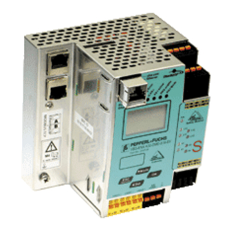
- Page 1 ACTORY UTOMATION ANUAL 3.0 PROFINET ATEWAY WITH INTEGR AFETY ONITOR...
- Page 2 AS-i 3.0 PROFINET Gateway with integr. Safety Monitor With regard to the supply of products, the current issue of the following document is applicable: The General Terms of Delivery for Products and Services of the Electrical Industry, published by the Central Association of the Electrical Industry (Zentralverband Elektrotechnik und Elektroindustrie (ZVEI) e.V.) in its most recent version as well as the supplementary clause: "Expanded reservation of proprietorship"...
-
Page 3: Table Of Contents
AS-i 3.0 PROFINET Gateway with integr. Safety Monitor Table of contents Table of contents Introduction...................8 Declaration of conformity ..............9 Declaration of conformity................9 Safety ....................10 Symbols relevant to safety................10 General notes on safety ................10 Disposal ......................10 General .................... - Page 4 AS-i and power supply terminal assignments ..........51 9.4.1 Electrical connection VBG-PN-K30-D-S16 ..............52 9.4.2 Electrical connection VBG-PN-K30-DMD-S16-EV............53 9.4.3 Electrical connection VBG-PN-K30-DMD-S16, VBG-PNS-K30-DMD ......54 Diagnostics interface ..................55 9.5.1 Diagnostics port RS 232 ....................55 PROFINET interface..................55 Safe coupling via Ethernet ......(VBG-PN-K30-DMD-S16-EV)56 Chip card ......................56...
- Page 5 AS-i 3.0 PROFINET Gateway with integr. Safety Monitor Table of contents Release circuits....................57 9.9.1 Wiring overview - safety unit ..................57 9.10 Indicators and operating elements............... 58 9.10.1 LED indicators – master....................58 9.10.2 LED indicators - safety unit ..................59 9.10.3 Buttons ...........................60 Function and startup of the Safety Monitor ........
- Page 6 AS-i 3.0 PROFINET Gateway with integr. Safety Monitor Table of contents 12.4.3 Noise Detector .......................78 12.4.4 Over-voltage Detector ....................78 12.5 Functions of the new generation of AS-i Gateways ........79 12.5.1 C-programmable Gateways ..................79 12.5.2 Interchangeable memory card..................79 12.5.3 Earth fault monitor......................79 12.5.4 Current can be read directly on the unit..............80 12.5.5...
- Page 7 AS-i 3.0 PROFINET Gateway with integr. Safety Monitor Table of contents 17.3 Diagnostics ....................115 Glossary .................... 117 Appendix, Examples................. 120 19.1 Startup on a Siemens NC control ............... 120 19.1.1 Setting in the S7 configuration...................120 19.1.2 Setting in the NC control.....................121 19.1.3 Setting “PROFISAFE_IN_ADDRESS“...
-
Page 8: Introduction
Introduction Introduction Congratulations You have chosen a device manufactured by Pepperl+Fuchs. Pepperl+Fuchs de- velops, produces and distributes electronic sensors and interface modules for the market of automation technology on a worldwide scale. Before installing this equipment and put into operation, read this manual carefully. -
Page 9: Declaration Of Conformity
This product was developed and manufactured under observance of the applica- ble European standards and guidelines. Information! A Declaration of Conformity can be requested from the manufacturer. The product manufacturer, Pepperl+Fuchs GmbH, D-68307 Mannheim, has a certified quality assurance system that conforms to ISO 9001. -
Page 10: Safety
If serious faults occur, stop using the de- vice. Secure the device against inadvertent operation. In the event of repairs, re- turn the device to your local Pepperl+Fuchs representative or sales office. The connection of the device and maintenance work when live may only be car- ried out by a qualified electrical specialist. -
Page 11: General
"no, max. 8A/AS-i network": 1 power supply per AS-i network Ethernet fieldbus + RS 232: Access to AS-i master and safety monitor via Pepperl+Fuchs proprietary software over Ethernet fieldbus interface or RS 232 interface and adapter cable. AS-i Power24V capable:... -
Page 12: As-I 3.0 Gateway Profinet Via Profisafe
AS-i 3.0 PROFINET Gateway with integr. Safety Monitor General The AS-i 3.0 PROFINET Gateway with integr. Safety Monitor combines two de- vices in one housing: an AS-i/PROFINET Gateway and a Safety Monitor for 2 AS- i circuits. The safety unit provides 4 inputs which can be defined as either EDM or as START inputs. -
Page 13: New Generation Of As-I Gateways With Ethernet Diagnostics Interface
AS-i 3.0 PROFINET Gateway with integr. Safety Monitor General Commissioning, debugging and setting up of the AS-i parameters can be accom- plished with the use of the display, but it can also be handled via the diagnostic in- terface and the field bus. New Generation of AS-i Gateways with ethernet diagnostics interface The plus points of the new Gateway generation at a glance: •... -
Page 14: Brief Description
AS-i 3.0 PROFINET Gateway with integr. Safety Monitor General Brief description The actuator-sensor interface (AS-i) has established itself as a system for net- working primarily binary sensors and actuators at the lowest level of the automa- tion hierarchy. The high number of installed systems, the ease of use and the reli- able operating behaviour also make the AS-i interesting in the area of machine safety. - Page 15 AS-i 3.0 PROFINET Gateway with integr. Safety Monitor General AS-i 3.0 PROFINET Gateway with integr. Safety Monitor The AS-i/PROFINET Gateway monitors within an AS-i system the safe slaves which have been assigned according to the configuration specified by the user with the configuration software.
-
Page 16: Specifications - As-I/Profinet Gateways
AS-i 3.0 PROFINET Gateway with integr. Safety Monitor Specifications - AS-i/PROFINET Gateways Specifications - AS-i/PROFINET Gateways Technical data The technical data are placed in the data sheet. Please view the current version on the web page: http://www.pepperl-fuchs.com. Attention! The AS-I power supply for the AS-I components must have isolation per IEC 60 742 and be able to handle momentary power interruptions of up to 20 ms. -
Page 17: Safety-Relevant Characteristic Data
AS-i 3.0 PROFINET Gateway with integr. Safety Monitor Specifications - AS-i/PROFINET Gateways Safety-relevant characteristic data Characteristic data Value Standard Safety category EN 954-1 Safety category EN ISO 13849-1: 2008 Performance Level (PL) Safety Integrity Level (SIL) EN 61508: 2001 Lifespan (TM) in years EN ISO 13849-1: 2008 Maximum switch-on time in months EN 61508: 2001... -
Page 18: Overview Of Parameter For Determining The Failure Rates
AS-i 3.0 PROFINET Gateway with integr. Safety Monitor Specifications - AS-i/PROFINET Gateways 5.2.1 Overview of parameter for determining the failure rates nop/y switching intervals B10d electromechanics Standard value cycle MTTF [years] PFH [1/h] 105.120 2.500.000 237,82 EN ISO 9,908 x 10 13849-1 52.560 475,65... -
Page 19: Reaction Times
AS-i 3.0 PROFINET Gateway with integr. Safety Monitor Specifications - AS-i/PROFINET Gateways Reaction times 5.3.1 Sensor -> local relay output 1.13 2.13 1.14 2.14 Sensor = 40ms react = maximal reaction time of the sensor (see data sheet) = maximal system reaction time react 5.3.2 Sensor ->... -
Page 20: Sensor -> As-I Relay Output
AS-i 3.0 PROFINET Gateway with integr. Safety Monitor Specifications - AS-i/PROFINET Gateways 5.3.3 Sensor -> AS-i relay output 1.13 1.14 1.23 1.24 Sensor Relay output = 85ms react = maximal reaction time of the sensor (see data sheet) = maximal system reaction time react 5.3.4 Sensor ->... -
Page 21: System Reaction Times - Example Calculations
AS-i 3.0 PROFINET Gateway with integr. Safety Monitor Specifications - AS-i/PROFINET Gateways 5.3.5 System reaction times – example calculations System components: ASI1 AS-i network 1 ASI2 AS-i network 2 S1-1 Safe sensor slave (EMERGENCY-OFF switch: t = 100 ms) R S1-1 S1-2 Safe sensor slave (safety light barrier: t... - Page 22 AS-i 3.0 PROFINET Gateway with integr. Safety Monitor Specifications - AS-i/PROFINET Gateways System configuration - example 1: Calculation of the system reaction time SM1-1 SM1-2 AS-i Safety Monitor AS-i Safety Monitor S1-1 S1-2 AS-i 1 SM2-1 AS-i Safety Monitor S2-1 A2-1 I –...
- Page 23 AS-i 3.0 PROFINET Gateway with integr. Safety Monitor Specifications - AS-i/PROFINET Gateways System configuration - example 2: Calculation of the system reaction time SM1-1 SM1-2 AS-i Safety Monitor AS-i Safety Monitor S1-1 S1-2 AS-i 1 SM2-1 AS-i Safety Monitor S2-1 A2-1 I –...
-
Page 24: Scope Of Delivery
AS-i 3.0 PROFINET Gateway with integr. Safety Monitor Specifications - AS-i/PROFINET Gateways System configuration - example 3: Calculation of the system reaction time SM1-1 SM1-2 AS-i Safety Monitor AS-i Safety Monitor S1-1 S1-2 AS-i 1 SM2-1 AS-i Safety Monitor S2-1 A2-1 I –... -
Page 25: Specifications - As-I/Profisafe Gateway
AS-i 3.0 PROFINET Gateway with integr. Safety Monitor Specifications - AS-i/PROFIsafe Gateway Specifications - AS-i/PROFIsafe Gateway Technical data The technical data are placed in the data sheet. Please view the current version on the web page: http://www.pepperl-fuchs.com. Attention! The AS-I power supply for the AS-I components must have isolation per IEC 60 742 and be able to handle momentary power interruptions of up to 20 ms. -
Page 26: Safety-Relevant Characteristic Data
AS-i 3.0 PROFINET Gateway with integr. Safety Monitor Specifications - AS-i/PROFIsafe Gateway Safety-relevant characteristic data Characteristic data Value Standard Safety category EN 954-1 EN ISO 13849-1: 2008 Performance Level (PL) EN ISO 13849-1: 2008 Safety Integrity Level (SIL) IEC 61508: 2001 Lifespan (TM) in years EN ISO 13849-1: 2008 Maximum switch-on time in months... -
Page 27: Reaction Times
AS-i 3.0 PROFINET Gateway with integr. Safety Monitor Specifications - AS-i/PROFIsafe Gateway Reaction times 6.3.1 Ethernet (PROFIsafe) -> local relay output 1.13 2.13 1.14 2.14 = 15ms ethernet react = reaction time PROFIsafe type 150ms ethernet = maximal system reaction time react 6.3.2 Ethernet (PROFIsafe) ->... -
Page 28: Ethernet (Profisafe) -> As-I Relay Output
AS-i 3.0 PROFINET Gateway with integr. Safety Monitor Specifications - AS-i/PROFIsafe Gateway 6.3.3 Ethernet (PROFIsafe) -> AS-i relay output 1.13 1.14 1.23 1.24 Relay output = 60ms ethernet react = reaction time PROFIsafe type 150ms ethernet = maximal system reaction time react 6.3.4 Ethernet (PROFIsafe) ->... -
Page 29: Installation
AS-i 3.0 PROFINET Gateway with integr. Safety Monitor Installation Installation Dimensions Warning! Cover the top of the gateway when doing any drilling work above the unit. No particles, especially metal chips, should be allowed to enter the housing, since this could cause a short circuit. -
Page 30: Installing In The Control Cabinet
AS-i 3.0 PROFINET Gateway with integr. Safety Monitor Installation Installing in the control cabinet The AS-I/Gateway is installed in the control cabinet on 35mm DIN rails per DIN EN 50 022. Information! AS-I/Gateway The enclosure of the is made of stainless steel. The unit is also sui- table for exposed wall mounting. -
Page 31: Commissioning
AS-i 3.0 PROFINET Gateway with integr. Safety Monitor Installation Commissioning 7.5.1 Switching to advanced display mode classical display advanced display mode 1.12A PROFINET QUICK SETUP AS-I SAFETY UNKNOWN SLAVE DIAGNOSIS menu structure see additional page ESC/Service 7.5.2 Setting the PROFINET properties PROFINET CONFIGURATION TCP/IP... -
Page 32: Setting The Profisafe Address
AS-i 3.0 PROFINET Gateway with integr. Safety Monitor Installation PROFINET 100BASE-TX FDX oder/or/ou/o/o TCP/IP 100BASE-TX HDX ETHERNET 10BASE-T FDX 10BASE-T HDX NO CONNECTION ETHERNET: PORT 1 MODE: 100BASE-TX FDX PORT 2 MODE: NO CONNECTION MAC ID DEVICE: TCP/IP 00-16-77-10- ACTUAL VALUES AF-8C CONFIGURATION MAC ID PORT 1:... -
Page 33: Connecting As-I Slaves
AS-i 3.0 PROFINET Gateway with integr. Safety Monitor Installation PROFINET PROFISAFE ADDR. QUICK SETUP Status SAFETY PROFISAFE ADDR. ↓ PROFINET QUICK SETUP SAFETY ↓ PROFISAFE ADDR. ↓ ASI SAFETY SAFE OUTPUT CH PROFISAFE START/STOP 7.5.4 Connecting AS-i Slaves Power Power PROFINET PROFINET 1. -
Page 34: Quick Setup
AS-i 3.0 PROFINET Gateway with integr. Safety Monitor Installation 7.5.5 Quick setup config error 1. 5 STORE AS-I CONFIGURATION STORE +PRJ MODE 1xOK ↓ config error PROFINET QUICK SETUP ASI SAFETY CONFIGURATION OK DIAGNOSIS Host error no connection 1: ON 2: OFF WARNING: OUTPUTS MAY BE RESET... -
Page 35: Error Tracing
AS-i 3.0 PROFINET Gateway with integr. Safety Monitor Installation 7.5.6 Error tracing 7.5.6.1 Faulty slaves Power PROFINET Config error U AS-i AS-i active prg enable MISSING SLAVE prj mode AS-i AS-i Slave 1 1.24 AS-i Slave 5 MISSING SLAVE AS-i Slave 24 7.5.6.2 Error display (last error) -
Page 36: Addressing
AS-i 3.0 PROFINET Gateway with integr. Safety Monitor Installation Addressing 7.6.1 Assigning address 15 to slave currently at address 2 1. 41 ↓ SEARCHING SLAVE SLAVE ADR TOOL OLD ADDRESS NEW ADDRESS 0 ↓ QUICK SETUP SLAVE ADR TOOL AS-I SAFETY OLD ADDRESS DIAGNOSIS NEW ADDRESS 15... -
Page 37: Local Parameter Setting Of Safe As-I Gateways And Monitors
AS-i 3.0 PROFINET Gateway with integr. Safety Monitor Installation Local parameter setting of safe AS-i Gateways and Monitors... - Page 38 AS-i 3.0 PROFINET Gateway with integr. Safety Monitor Installation For further information see manual, section <Chip card>...
-
Page 39: Replacing A Defective Safety-Related As-I Slave
The new slave must be able to send code sequences and must have the same address as the old one. The addressing of the new slave is carried out automatically by default for all Pepperl+Fuchs AS-i Masters. Only one missing slave is allowed! ESC/Service... -
Page 40: Replacing The Chip Card
AS-i 3.0 PROFINET Gateway with integr. Safety Monitor Installation Replacing the chip card Always turn off power before inserting or removing the card! 7.10 Replacing a defective device If Safe Link is used, it is necessary to teach the group manager after replacing a defective device (see next section)! - Page 41 AS-i 3.0 PROFINET Gateway with integr. Safety Monitor Installation...
- Page 42 AS-i 3.0 PROFINET Gateway with integr. Safety Monitor Installation |COPY BANK A |COPY BANK A ↓ |TO MONITOR |TO MONITOR |MASTER |MASTER ↓ | |CONFIGURATION ↓ | |CONFIGURATION |RELEASE CODE |FFFF |----------------| |TYPE CODE ? |RELEASE CODE |FFFF |----------------| |TYPE CODE ? |0000 |RELEASE CODE ↓...
-
Page 43: Teaching The Group Manager After Replacing A Device
AS-i 3.0 PROFINET Gateway with integr. Safety Monitor Installation 7.10.1 Teaching the group manager after replacing a device |QUICK SETUP ↓ |SAFETY |DIAGNOSIS |SLAVE ADR TOOL |AS-SAFETY |SAFE OUTPUT CH ↓ |START/STOP |CLEAR SAFE CFG |PIN |PROTECT |SWITCH CYCLES |CROSS COMM. |INTERFACE |NODE STATUS ↓... -
Page 44: Replacing The Monitor
AS-i 3.0 PROFINET Gateway with integr. Safety Monitor Installation 7.11 Replacing the monitor "1"+ "2" "2" "1" AS-i 1 AS-i 2 "2"+ "1" "1" "2" AS-i 1 AS-i 2 "2" "1"+ "2" "1" "1"+ "2" "1" "2" AS-i 1 AS-i 2... - Page 45 AS-i 3.0 PROFINET Gateway with integr. Safety Monitor Installation Safety configuration + AS-i configuration different! "1" "2" |Error: |Chip Card and |Safety Data |Different. |Delete Chip |Card or Safety |Data |Chipcard and ↓ |AS-i Data |Different |Chipcard->Master| |Master->Chipcard| |Continue ☺Press OK for Menu Output Circuit 1:OFF 2:OFF...
- Page 46 AS-i 3.0 PROFINET Gateway with integr. Safety Monitor Installation |ENTER PIN ↓ |0000 |SELECT BANK ↓ |STOP MONITOR ↓ |COPY BANK A to ↓ |MONITOR |RELEASE DATE: |2006/06/17 18:43 |BY: |ROLF BECKER |CONFIG NAME: |TEST SOFTWARE |INSTALLATION |INSTRUCTION V1.00 |RELEASE CODE: |1BDF |-------------------| |TYPE CODE...
-
Page 47: Safe Configuration Using Asimon 3 G2
AS-i 3.0 PROFINET Gateway with integr. Safety Monitor Installation Safety configuration + AS-i configuration identic! AS-i 1 AS-i 2 7.12 Safe configuration using ASIMON 3 G2 ASIMON 3 G2 Software Start Before commissioning the safety unit, put the gateway into operation! ASIMON 3 G2 Software Change the preset password during the first use of the device (Monitor/change password)! ASIMON 3 G2 Software... - Page 48 AS-i 3.0 PROFINET Gateway with integr. Safety Monitor Installation ASIMON 3 G2 Software You can acknowledge the request TEACH CODE SEQUENCES? selecting "Yes", or you can do it later via display selecting "No". ASIMON 3 G2 Software Check the configuration log (respect instructions in <chap. 5.8> of the ASIMON manual!). ASIMON 3 G2 Software Validate the configuration with MONITOR –>...
-
Page 49: Maintenance
AS-i 3.0 PROFINET Gateway with integr. Safety Monitor Maintenance Maintenance Checking for safe turn-off The safety representative is responsible for checking flawless function of the AS-i Safety Monitor within the safety system. Safe turn-off when an associated safe sensor or switch is triggered must be checked at least once a year. -
Page 50: Electrical Connection
AS-i 3.0 PROFINET Gateway with integr. Safety Monitor Electrical connection Electrical connection Overview of terminals, indicators and operating elements 9.1.1 VBG-PN-K30-D-S16, VBG-PN-K30-DMD-S16, VBG-PNS-K30-DMD, VBG-PN- K30-DMD-S16-EV 0,2 ... 2,5 mm 0,2 ... 2,5 mm 24 ... 12 Legend: LEDs PROFINET interface LC display Buttons Terminals: Supply voltage and AS-i circuit... -
Page 51: As-I Bus Connection
AS-i 3.0 PROFINET Gateway with integr. Safety Monitor Electrical connection AS-i bus connection Blue Brown Blue Brown AS-i- AS-i+ AS-i- AS-i+ 2-conductor AS-i round cable Yellow ASi ribbon cable (Recommended: flexible power cable H05VV-F2x1,5 per DIN VDE 0281) Information! Electrical work is to be performed only by electrical technicians. Information about the device types Information! A listing of the individual devices and their features can be found in section <Product... -
Page 52: Electrical Connection Vbg-Pn-K30-D-S16
AS-i 3.0 PROFINET Gateway with integr. Safety Monitor Electrical connection 9.4.1 Electrical connection VBG-PN-K30-D-S16 Gateway Safety Unit ASI 1 +ASI 2- +ASI 1 +ASI 1 +PWR- 24V 0V 5 mm max! Function ground +ASI 1– +ASI 1– ASI 1 +PWR– (max. 8A) +ASI 2–... -
Page 53: Electrical Connection Vbg-Pn-K30-Dmd-S16-Ev
AS-i 3.0 PROFINET Gateway with integr. Safety Monitor Electrical connection 9.4.2 Electrical connection VBG-PN-K30-DMD-S16-EV Gateway Safety Unit +ASI PWR- +ASI 1 +ASI 1 +ASI 2 24V 0V 5 mm max! Function ground +ASI 1– +ASI 1– +ASI 2– ASI +PWR– (max. 8A) -
Page 54: Electrical Connection Vbg-Pn-K30-Dmd-S16, Vbg-Pns-K30-Dmd
AS-i 3.0 PROFINET Gateway with integr. Safety Monitor Electrical connection 9.4.3 Electrical connection VBG-PN-K30-DMD-S16, VBG-PNS-K30-DMD Gateway Safety Unit 5 mm max! Function ground +ASI 1– ASI 1 +PWR– (max. 8A) +ASI 2– ASI 2 +PWR– (max. 8A) Terminal Signal / Description +ASI 1–... -
Page 55: Diagnostics Interface
AS-i 3.0 PROFINET Gateway with integr. Safety Monitor Electrical connection Diagnostics interface The service and diagnostics interface (in conjunction with AS-i Control Tools or ASIMON 3 G2 software) is used for communication between the PC and the unit. 9.5.1 Diagnostics port RS 232 The service and diagnostics interface is configured as a mini DIN-6 female and it is placed on the front plate, on the left hand side. -
Page 56: Safe Coupling Via Ethernet
AS-i 3.0 PROFINET Gateway with integr. Safety Monitor Electrical connection Safe coupling via Ethernet (VBG-PN-K30-DMD-S16-EV) The device supports Safe Link via Ethernet. In order to establish a safe coupling between several devices, they should be connected via the ethernet diagnostics interface to a switch. -
Page 57: Release Circuits
AS-i 3.0 PROFINET Gateway with integr. Safety Monitor Electrical connection Release circuits 9.9.1 Wiring overview - safety unit 1.13 24 V 2.13 2.Y2 2.Y1 1.Y1 1.Y2 2.Y1 2.Y2 1.Y1 1.Y2 1.14 3.14 4.14 2.14 1.Y1 (EDM 1/Start 1), 2.Y1 (EDM 2/Start 2), 1.Y2 (EDM 3/Start 3), 2.Y2 (EDM 4/Start 4) The safety unit provides 4 inputs. -
Page 58: Indicators And Operating Elements
AS-i 3.0 PROFINET Gateway with integr. Safety Monitor Electrical connection 9.10 Indicators and operating elements 9.10.1 LED indicators – master The LED’s on the front panel of the device indicate: Power The master is receiving sufficient power. PROFINET Green: PROFINET controller connected (otherwise LED flashes red) config error Configuration error. -
Page 59: Led Indicators - Safety Unit
AS-i 3.0 PROFINET Gateway with integr. Safety Monitor Electrical connection 9.10.2 LED indicators - safety unit 1.13 24 V 2.13 2.Y2 2.Y1 1.Y1 1.Y2 2.Y1 2.Y2 1.Y1 1.Y2 1.14 3.14 4.14 2.14 The LED’s on the safety unit indicate: 24 V supply for the semiconductor outputs is present. 1Y.1, 1Y2, 2Y.1, 2Y.2 Input 1.Y1 (EDM 1/Start 1), 2.Y1 (EDM 2/Start 2), 1.Y2 (EDM 3/Start 3), 2.Y2 (EDM 4/Start 4) is turned on. -
Page 60: Buttons
AS-i 3.0 PROFINET Gateway with integr. Safety Monitor Electrical connection 9.10.3 Buttons The buttons are used for the following: ⇑ Mode/ Switching between configuration mode and protected operating mode, and saving the current AS-i configuration as the nominal configuration. Set/⇓ Selecting the address of and assigning an address to a slave. -
Page 61: Function And Startup Of The Safety Monitor
AS-i 3.0 PROFINET Gateway with integr. Safety Monitor Function and startup of the Safety Monitor Function and startup of the Safety Monitor Configuration and startup of the AS-i Safety Monitor is accomplished using a PC/ Notebook and the ASIMON 3 G2 configuration software. The operating language of the device can be set for the respective country (see section <Operation in advanced display mode>). -
Page 62: Description Of Configuration Using Asimon 3 G2 Software
AS-i 3.0 PROFINET Gateway with integr. Safety Monitor Function and startup of the Safety Monitor Using a chip card with complete configuration In contrast to the master configuration, the complete configuration also con- tains the code sequences for all included slaves. Sending the complete con- figuration from the chip card to the Safety Monitor can make replacement of the device enormously simpler and faster. -
Page 63: Description Of Configuration Using Chip Card With Master Configuration
AS-i 3.0 PROFINET Gateway with integr. Safety Monitor Function and startup of the Safety Monitor 10.2.2 Description of configuration using chip card with master configuration Generating a master configuration: • Generate a configuration using the ASIMON 3 G2 software • Load the configuration into the device •... -
Page 64: Safety-Relevant Documentation Of The Application
AS-i 3.0 PROFINET Gateway with integr. Safety Monitor Function and startup of the Safety Monitor Attention! Safety advisory: Power must always be turned off when removing or inserting the chip card! Ensure that the chip card contains the configuration intended for and released for the application! This can be done by comparing the release codes on the display (section <Ope- ration in advanced display mode>):... -
Page 65: Diagnostics Of Release Circuits 1-4 Via The Binary Data
AS-i 3.0 PROFINET Gateway with integr. Safety Monitor Function and startup of the Safety Monitor • Fieldbus interface 10.4.1 Diagnostics of release circuits 1-4 via the binary data If monitor slaves with base address +1 and +2 exist, the state of several OSSDs is transmitted there. -
Page 66: Diagnostic Values In The Idi
VBG-PNS-K30-DMD ident. no. 15050 15054 • VBG-PN-K30-DMD-S16 ident. no. • VBG-PN-K30-DMD-S16-EV ≥ ≥ 15051 ident. no. 15216 The input values for safety-relevant input slaves can be substituted in various ways. This makes the diagnostics information available directly in the cyclical I/O data. -
Page 67: Password Protection
AS-i 3.0 PROFINET Gateway with integr. Safety Monitor Function and startup of the Safety Monitor Information! The color and thereby the status of the component do not always have to agree with the switching state of the input channels. In case of lost telegrams, untaught slaves or non-synchronous switching of the two channels, error and test states may result (red flashing and yellow flashing). -
Page 68: Procedure For Configuring And Teaching Code Sequences
AS-i 3.0 PROFINET Gateway with integr. Safety Monitor Function and startup of the Safety Monitor 10.6.1 Procedure for configuring and teaching code sequences The configuration is created using ASIMON 3 G2 software, loaded into the safety unit and released. The name of the person releasing and the date are stored at this moment. -
Page 69: Function Of The Esc/Service Key
AS-i 3.0 PROFINET Gateway with integr. Safety Monitor Function and startup of the Safety Monitor 10.6.2 Function of the ESC/Service key In traditional (classical) display mode, the ESC/Service key takes on two kinds of functions: • Briefly pressing the ESC/Service key unlocks the Safety Monitor when red is flashing •... -
Page 70: 10.8.1.2 Data Not Compatible
AS-i 3.0 PROFINET Gateway with integr. Safety Monitor Function and startup of the Safety Monitor 10.8.1.2 Data not compatible If a card is found whose data are incompatible with the device, the following error message is displayed: CHIPCARD NOT COMPATIBLE 10.8.1.3 Card empty The following message is displayed for an empty card: CHIPCARD FOUND... -
Page 71: Safe Data
AS-i 3.0 PROFINET Gateway with integr. Safety Monitor Function and startup of the Safety Monitor CHIPCARD AND AS-I DATA DIFFERENT CARD->MASTER MASTER->CARD CONTINUE Description CHIP CARD>MASTER: Chip card data are copied to the master MASTER->CHIPCARD: Master data are copied to the chip card NEXT: No change to the data The menu can be exited by pressing the ESC/Service key without changing the data. -
Page 72: 10.8.2.3 Complete Configuration
AS-i 3.0 PROFINET Gateway with integr. Safety Monitor Function and startup of the Safety Monitor 10.8.2.3 Complete configuration If when starting with an empty device a card with a released safety configuration including code sequences is found (Complete safety configuration) in the active memory bank, this configuration is written to the device, then the menu for releas- ing using Release Code is opened: COPY BANK A... -
Page 73: 10.8.2.6 Operating The Chip Card From The Menu
AS-i 3.0 PROFINET Gateway with integr. Safety Monitor Function and startup of the Safety Monitor The safety unit will not operate in this case. You must either clear the device or the active bank via menu. 10.8.2.6 Operating the chip card from the menu The data on the chip card can, as described in section <SAFE CHIPCARD>, be exchanged between the Monitor and the chip card. - Page 74 AS-i 3.0 PROFINET Gateway with integr. Safety Monitor Function and startup of the Safety Monitor Attention! Safety advisory: Ensure that the configuration intended for and released for the application is used! This can be done by comparing the release codes on the display (See section <MONITOR CONFIG>): •...
-
Page 75: Operation In Advanced Display Mode
AS-i 3.0 PROFINET Gateway with integr. Safety Monitor Operation in advanced display mode Operation in advanced display mode Information! You will find a description of the display menu in the separate document "Display_Menue". -
Page 76: Advanced Diagnostics For As-I Masters
AS-i 3.0 PROFINET Gateway with integr. Safety Monitor Advanced Diagnostics for AS-i Masters Advanced Diagnostics for AS-i Masters The advanced AS-i diagnostics is intended to localize occasionally occurring con- figuration errors and to determine the quality of data transmission on AS-i without using additional diagnostics tools. -
Page 77: Offline Phase For Configuration Errors
AS-i 3.0 PROFINET Gateway with integr. Safety Monitor Advanced Diagnostics for AS-i Masters 12.3 Offline Phase for Configuration Errors The AS-i masters with advanced diagnostics offer the possibility to set them- selves into the offline phase when a configuration error occurs and thus are able to transition the AS-i network into a safe operational state. -
Page 78: Earth/Ground Fault Detector
AS-i 3.0 PROFINET Gateway with integr. Safety Monitor Advanced Diagnostics for AS-i Masters 12.4.2 Earth/Ground Fault Detector An Earth/Ground Fault exists when the voltage (Nominal value of =0,5 U .) is outside of the following range: AS-i ≤ U ≤ 90% U 10% U AS-i AS-i... -
Page 79: Functions Of The New Generation Of As-I Gateways
AS-i 3.0 PROFINET Gateway with integr. Safety Monitor Advanced Diagnostics for AS-i Masters 12.5 Functions of the new generation of AS-i Gateways The new generation scores with further optimized diagnostics, several additional functions and even greater operating convenience. Information! A listing of the individual devices and their features can be found in section <New Generation of AS-i Gateways with ethernet diagnostics interface>. -
Page 80: Current Can Be Read Directly On The Unit
AS-i 3.0 PROFINET Gateway with integr. Safety Monitor Advanced Diagnostics for AS-i Masters or on a sensor line. Earth fault sen. The menu EFLT Ratio shows the asymmetry of the AS-i network, referenced to ground (see sketch). 100% AS-i + 100% AS-i - EFLT Ratio:... -
Page 81: Self-Resetting Fuses
AS-i 3.0 PROFINET Gateway with integr. Safety Monitor Advanced Diagnostics for AS-i Masters Maximal: 1,3A current: 0,3A Current: 0,3A Current limiting 3,2A 12.5.5 Self-resetting fuses Main menu || SETUP || CURRENT LIMIT || Thanks to self-resetting fuses in the "1 Gateway, 1 power supply for 2 AS-i cir- cuits"... -
Page 82: Ethernet Diagnostics Interface With Web Server
AS-i 3.0 PROFINET Gateway with integr. Safety Monitor Advanced Diagnostics for AS-i Masters AS-i Power AS-i PWR Supply change 12.5.7 Ethernet diagnostics interface with web server These devices allow diagnostics for both the Gateway and the AS-i networks (in- cluding Safety technology) over Ethernet without additional software. AS-i net- work can be thus a part of a remote maintenance concept. -
Page 83: Configuration Of As-I/Profinet Gateways
During the configuration, the GSDML file must be imported into the PROFINET configuration tool. The AS-i/PROFINET Gateway appears then in the hardware catalog as: "PROFINET IO/Other field devices/Gateway/Pepperl+Fuchs AS-interface". Information! The device name of the AS-i 3.0 PROFINET-Gateway is: "". Any PROFINET partici- pant will be identified over this name. - Page 84 AS-i 3.0 PROFINET Gateway with integr. Safety Monitor Configuration of AS-i/PROFINET Gateways Length description 12 byte I/O command interface 32 byte I/O 34 byte I/O 36 byte I/O Tab. 13-12. Length description 2 byte … 128 byte I analog input data, dynamic 2 byte …...
- Page 85 AS-i 3.0 PROFINET Gateway with integr. Safety Monitor Configuration of AS-i/PROFINET Gateways Information! Available only with AS-i PROFIsafe Gateways. EC-flags (16-bit) EC-flags (16-bit) byte 0 – – – byte 1 Tab. 13-16. DA: Double address NSE Noise OV: Overvoltage EF: Earth falut Pok: Periphery_Ok OR: Offline_Ready APF: APF...
-
Page 86: Bytes Digital As-I I/O Data (A And B Slaves)
AS-i 3.0 PROFINET Gateway with integr. Safety Monitor Configuration of AS-i/PROFINET Gateways AAv 1 = ’Auto_Address_Available’ active 0 = ’Auto_Address_Available’ not active CA 0 = ’Configuration_Active’ not active 1 = ’Configuration_Active’ active NA 0 = ’Normal_Operation_Active’ OK 1 = ’Normal_Operation_Active’ not OK APF 0 = no APF 1 = APF OR 0 = online... - Page 87 AS-i 3.0 PROFINET Gateway with integr. Safety Monitor Configuration of AS-i/PROFINET Gateways Input and Output Data Image Byte slave 20/20A slave 21/21A slave 22/22A slave 23/23A slave 24/24A slave 25/25A slave 26/26A slave 27/27A slave 28/28A slave 29/29A slave 30/30A slave 31/31A reserved slave 1B...
-
Page 88: Bytes Digital As-I I/O Data (A Slaves Only)
AS-i 3.0 PROFINET Gateway with integr. Safety Monitor Configuration of AS-i/PROFINET Gateways 13.2.3 16 bytes digital AS-i I/O data (A slaves only) Modul: 16 byte digitale I/O (A) Module ident number 0x80000001 Name 16 byte digitale I/O (A) Details 16 bytes digital AS-i I/O data (A slaves only) Category digital I/O data Submodule:... -
Page 89: Words Analog As-I Input Data
AS-i 3.0 PROFINET Gateway with integr. Safety Monitor Configuration of AS-i/PROFINET Gateways Information! For information about I/O data image, refer to the table <Input and Output Data Image>. 13.2.5 4 words analog AS-i input data Modul: 4 words analog E Module Ident 0x80000005 Number... - Page 90 AS-i 3.0 PROFINET Gateway with integr. Safety Monitor Configuration of AS-i/PROFINET Gateways 16-bit value 16-bit value D15 D14 D13 D12 D11 D10 D9 D8 D7 D6 D5 D4 D3 D2 D1 D0 word 1 channel 1 word 2 channel 2 word 3 channel 3 word 4...
-
Page 91: Words Analog As-I Output Data
AS-i 3.0 PROFINET Gateway with integr. Safety Monitor Configuration of AS-i/PROFINET Gateways 13.2.6 4 Words analog AS-i output data Modul: 4 words analog Out Module ident 0x80000006 number Name 4 words analog out Details 4 words analog AS-i output data Category analog outputs Submodule:... -
Page 92: Bytes Command Interface
AS-i 3.0 PROFINET Gateway with integr. Safety Monitor Configuration of AS-i/PROFINET Gateways 13.2.7 36 bytes command interface Modul: 36 bytes Cmd If Module ident number 0x80000002 Name 36 bytes Cmd If Details 36 bytes command interface Category command interface Submodule: Submodule ident number 0x00000001 Cycl. -
Page 93: Bytes Command Interface
AS-i 3.0 PROFINET Gateway with integr. Safety Monitor Configuration of AS-i/PROFINET Gateways 13.2.8 34 bytes command interface Modul: 34 bytes Cmd If Module ident number 0x80000002 Name 34 bytes Cmd If Details 34 bytes command interface Category command interface Submodule: Submodule ident number 0x00000001 Cycl. -
Page 94: Byte Command Interface
AS-i 3.0 PROFINET Gateway with integr. Safety Monitor Configuration of AS-i/PROFINET Gateways 13.2.9 12 byte command interface Modul: 12 bytes Cmd If Module ident number 0x80000002 Name 12 bytes Cmd If Details 12 bytes command interface Category command interface Submodule: Submodule ident number 0x00000001 Cycl input data... -
Page 95: Profinet Diagnostics
AS-i 3.0 PROFINET Gateway with integr. Safety Monitor Configuration of AS-i/PROFINET Gateways 13.4 PROFINET diagnostics Description of the diagnostic data which are sent via the PROFINET diagnostics channel. 13.4.1 Channel error codes Slot chan- error error text help text type AS-i configuration error the actual configuration found on AS-i... -
Page 96: Manufacturer Specific Diagnostic
AS-i 3.0 PROFINET Gateway with integr. Safety Monitor Configuration of AS-i/PROFINET Gateways Slot channel code message incorrect target address invalid target address invalid source address invalid watchdog time submitted SIL-class is too high invalid CRC2-lenght invalid PROFIsafe-version CRC1 error parameter setting inconsistent iParCRC Tab. - Page 97 AS-i 3.0 PROFINET Gateway with integr. Safety Monitor Configuration of AS-i/PROFINET Gateways Byte message earth fault overvoltage noise double addressing Tab. 13-29. List of configuration errors structure 0xA2: circuit 1 structure 0xA3: circuit 2 Byte message slave 0: config error slave 1/1A: config error slave 2/2A: config error …...
- Page 98 AS-i 3.0 PROFINET Gateway with integr. Safety Monitor Configuration of AS-i/PROFINET Gateways Safety status (single- und A-slaves) structure 0xA8: circuit 1 structure 0xA9: circuit 2 Byte message SaW configuration operation slave 1/1A: yellow flashing slave 2/2A: yellow flashing … … …...
-
Page 99: Safety Control/Status
AS-i 3.0 PROFINET Gateway with integr. Safety Monitor Configuration of AS-i/PROFINET Gateways 13.4.3 Safety Control/Status In the fieldbus configuration the designator Safety Control/Status can be added as cyclical data. This is possible both for the integrated Safety Monitor and for 2nd generation Monitors. - Page 100 AS-i 3.0 PROFINET Gateway with integr. Safety Monitor Configuration of AS-i/PROFINET Gateways Coding of status bytes no device flashing red at least one device flash- ing red Tab. 13-35. The cyclical output identifier contains the 4 Safety Monitor bits 1.Y1, 1.Y2, 2.Y1 and 2.Y2.
-
Page 101: Diagnostics In The Cyclic Channel (10 Byte Safelink.diag.)
AS-i 3.0 PROFINET Gateway with integr. Safety Monitor Configuration of AS-i/PROFINET Gateways Safety Control-Status (only with PROFIsafe) Length description 32 byte I Safety Ctrl/Status (32 OSSD) 8 byte O 64 byte I Safety Ctrl/Status (64 OSSD) 16 byte O Tab. 13-38. 13.4.3.1 Diagnostics in the cyclic channel (10 Byte SafeLink.Diag.) With this very simple diagnostics, the basic status of SafeLink can be captured. -
Page 102: Device-Specific Parameters
AS-i 3.0 PROFINET Gateway with integr. Safety Monitor Configuration of AS-i/PROFINET Gateways st. adr 28 st. adr 27 st. adr 26 st. adr 25 reserved st. adr 31 st. adr 30 st. adr 29 node status node address domain no. manager adr Tab. -
Page 103: Media Redundancy Protocol Mrp
AS-i 3.0 PROFINET Gateway with integr. Safety Monitor Configuration of AS-i/PROFINET Gateways Language Selection of the displayed language. Default: no change of the displayed language. List of Configuration Errors The AS-i/PROFINET Gateway saves a list of all AS-i slaves which have triggered a present configuration error. -
Page 104: System Startup Using As-I Control Tools
AS-i 3.0 PROFINET Gateway with integr. Safety Monitor System startup using AS-i Control Tools System startup using AS-i Control Tools The Windows based software AS-i Control Tools enables an easy and clear con- figuration of the AS-i network. Information! AS-i Control Tools must be installed first! This way, the device driver is copied into the previous designed folder in AS-i Control Tools and should be recognized automatically. - Page 105 AS-i 3.0 PROFINET Gateway with integr. Safety Monitor System startup using AS-i Control Tools Click on a slave to open the dialog window 'slave configuration'. This window enables the user to edit a slave address and to set AS-i param- eters or AS-i configuration data.
- Page 106 AS-i 3.0 PROFINET Gateway with integr. Safety Monitor System startup using AS-i Control Tools Configuring the AS-i network is easily accomplished by first connecting each AS-i slave separately to the AS-i line and setting its address, followed by pressing the button “Store configuration”...
-
Page 107: Configuration With Windows Software Asimon 3 G2
AS-i 3.0 PROFINET Gateway with integr. Safety Monitor Configuration with Windows Software ASIMON 3 G2 Configuration with Windows Software ASIMON 3 G2 Information! Please note further information in the configuration software ASIMON 3 G2 for Win- dows. -
Page 108: Status Indication, Faults And Fault Elimination
Status indication, faults and fault elimination Status indication, faults and fault elimination 16.1 Spontaneous display of faults from the safety unit Spontaneous messages are displayed on Pepperl+Fuchs GmbH AS-i monitors as follows: • When both networks are operating without error, a smiley is displayed. -
Page 109: Replacing A Defective Safety-Configured As-I Slave
AS-i 3.0 PROFINET Gateway with integr. Safety Monitor Status indication, faults and fault elimination If the safety unit is in the red flashing state and no menu is open, the safety unit can be unlocked by pressing the ESC/Service key (Section <Function of the ESC/ Service key>). -
Page 110: Replacing A Defective As-I Safety Monitor
AS-i 3.0 PROFINET Gateway with integr. Safety Monitor Status indication, faults and fault elimination Attention! After replacing a defective safe AS-i slave, always check the correct function of the new slave. 16.3 Replacing a defective AS-i Safety Monitor If an AS-i Safety Monitor is defective and needs to be replaced, the replacement unit does not necessarily have to be newly configured using the ASIMON 3 G2 software, rather it is possible to copy the configuration of the defective device us- ing a chip card. - Page 111 AS-i 3.0 PROFINET Gateway with integr. Safety Monitor Status indication, faults and fault elimination Information! The default password (factory setting) of the AS-i safety monitor is "SIMON". If you would like to reconfigure the AS-i safety monitor, you must first change this default password to a new one known only to you as safety officer.
-
Page 112: Safe Link
AS-i 3.0 PROFINET Gateway with integr. Safety Monitor Safe Link Safe Link 17.1 General introduction Safe Link represents the most efficient and cost-effective way to link safe signals from multiple AS-i networks. As for an AS-i linking network, safe linking using potential-free contacts or safe electronic in- and outputs eliminates expensive and cumbersome wiring. -
Page 113: Configuration
AS-i 3.0 PROFINET Gateway with integr. Safety Monitor Safe Link 17.2 Configuration Safe Link Ethernet diagnostics interface 10Mbits, half-duplex Ports Depends on the Multicast group Port 1024 to 1038 Protocol Data packets 72 bytes per packet Average 286 packets per second Group organization Number max. -
Page 114: Configuration Using Asimon
AS-i 3.0 PROFINET Gateway with integr. Safety Monitor Safe Link 17.2.1 Configuration using ASIMON Complete configuration of Safe Link is done using the ASIMON software, in the "Monitor/Bus information" section [1] on the "Safe Link" tab [2]. Here the group and device addresses are assigned and the safe programs for the individual Gateways managed. -
Page 115: Diagnostics
AS-i 3.0 PROFINET Gateway with integr. Safety Monitor Safe Link 17.3 Diagnostics Directly on the device If a group member does not receive the expected messages from another mem- ber, it displays the device address of the missing Gateway together with the mes- sage "not active". - Page 116 AS-i 3.0 PROFINET Gateway with integr. Safety Monitor Safe Link Here you are shown the status and direction of communication between the indi- vidual group members in graphical format. Based on the arrow colors you can see which sections of communication may be associated with telegram errors. Information! Please refer here to the information in the ASIMON documentation in the <Safe Link diagnostics>...
-
Page 117: Glossary
AS-i 3.0 PROFINET Gateway with integr. Safety Monitor Glossary Glossary A/B slave An AS-i slave with extended addressing. The address range of an A/B slave ex- tends from 1A to 31A and 1B to 31B. AS-i Power Fail Voltage below the threshold on the AS-i cable. I/O code The first digit of the slave profile, which indicates how many in- and outputs the slave has. - Page 118 AS-i 3.0 PROFINET Gateway with integr. Safety Monitor Glossary Inclusion phase The AS-i master sends a command to an available slave address to detect new slaves. If no reply is received, it immediately begins with the next data exchange phase. LPF - List of Peripheral Faults The list of peripheral faults was introduced with specification 2.1.
- Page 119 AS-i 3.0 PROFINET Gateway with integr. Safety Monitor Glossary Single Slave A single slave can in contrast to a ⇒ A/B slave only be addressed from range 1 to 31; the fourth output data bit can be used. All slaves as defined by the older AS-i Specification 2.0 are single slaves.
-
Page 120: Appendix, Examples
AS-i 3.0 PROFINET Gateway with integr. Safety Monitor Appendix, Examples Appendix, Examples 19.1 Startup on a Siemens NC control The following example describes the settings needed for starting up a PROFIsafe Gateway on a Siemens NC control (here an 840dSL). To place the PROFIsafe Gateway in operation on a Siemens control, a few set- tings are needed for the Gateway to function. -
Page 121: Setting In The Nc Control
AS-i 3.0 PROFINET Gateway with integr. Safety Monitor Appendix, Examples 19.1.2 Setting in the NC control The “PROFISAFE_MASTER_ADDRESS“ is taken from the hardware configura- tion (F_Source_Address) and entered in number 10385. Example: 10385 (corresponds to 2002 decimal) 19.1.3 Setting “PROFISAFE_IN_ADDRESS“ The “PROFISAFE_IN_ADDRESS“... -
Page 122: Setting "Profisafe_Out_Assign
AS-i 3.0 PROFINET Gateway with integr. Safety Monitor Appendix, Examples 19.1.6 Setting “PROFISAFE_OUT_ASSIGN" Here you enter from which data range the safe output bits are taken from the OUTSE. Example: 10389[0] 001032 (The first 32 bits are mapped from 1 to 32). 10389[1] 033064 (The next 32 bits are mapped from 33 to 64). -
Page 123: Safety Diagnostics In The Input Data Image (Idi)
AS-i 3.0 PROFINET Gateway with integr. Safety Monitor Appendix, Examples 19.2 Safety diagnostics in the input data image (IDI) Information! This functionality is available only in certain models. For additional information see sec- tion <Diagnostic values in the IDI>. 19.2.1 Representation of the diagnostic information Diagnostics in the IDI is a way to get the most important diagnostics information into the controller without using a command interface (mailbox) and without addi-... -
Page 124: Other Representation Variants
AS-i 3.0 PROFINET Gateway with integr. Safety Monitor Appendix, Examples 19.2.2 Other representation variants In addition to the above, there are also the following variants for representing the diagnostics: • Safety code sequence: Sending of the code sequence, with no evaluation of the data; the current state is sent for each bit. - Page 125 AS-i 3.0 PROFINET Gateway with integr. Safety Monitor Appendix, Examples...
- Page 126 AS-i 3.0 PROFINET Gateway with integr. Safety Monitor Appendix, Examples...
-
Page 127: Reference List
AS-i 3.0 PROFINET Gateway with integr. Safety Monitor Reference List Reference List 19.1 Manual: “ASIMON 3 G2 Configuration Software“ This Manual contains a detailed description of the configuration software for the AS-i Safety Monitor. The manual is an important component of the documentation for the AS-i Safety Monitor. -
Page 128: Codes Indicated By The Display
AS-i 3.0 PROFINET Gateway with integr. Safety Monitor Codes indicated by the display Codes indicated by the display In the basic state of the configuration mode, the addresses of all detected slaves are displayed in two-second intervals. A blank display indicates that the LDS (List of Detected Slaves) is empty, no slaves were detected. - Page 129 AS-i 3.0 PROFINET Gateway with integr. Safety Monitor Codes indicated by the display Checksum error in the data menu. "breakpoint": Control III C program in break point. Error while attempting to exit the configuration mode: A slave with address zero exists. General error while changing a slave address The front panel operation is blocked.
Need help?
Do you have a question about the VBG-PN-K30-DMD-S16-EV and is the answer not in the manual?
Questions and answers