YASKAWA E-V Series User Manual
Ac, dc power input, rotational motor, mechatrolink-ii communications reference, servomotor, servopack
Hide thumbs
Also See for E-V Series:
- User manual (435 pages) ,
- User manual (123 pages) ,
- User manual (357 pages)
Table of Contents
Advertisement
Quick Links
AC Servo Drives
DC Power Input
USER'S MANUAL
Design and Maintenance
Rotational Motor
MECHATROLINK-II Communications Reference
SGMMV Servomotor
SGDV SERVOPACK
MANUAL NO. SIEP S800000 82A
Σ
V
-
Series
Wiring and Connection
Utility Functions (Fn
Monitor Displays (Un
Troubleshooting
1
Outline
2
SigmaWin+
3
4
Operation
5
Adjustments
6
)
7
)
8
9
Appendix
Advertisement
Table of Contents
Troubleshooting

Subscribe to Our Youtube Channel
Related Manuals for YASKAWA E-V Series


Summary of Contents for YASKAWA E-V Series
- Page 1 AC Servo Drives Σ DC Power Input Series USER'S MANUAL Design and Maintenance Rotational Motor MECHATROLINK-II Communications Reference SGMMV Servomotor SGDV SERVOPACK Outline SigmaWin+ Wiring and Connection Operation Adjustments Utility Functions (Fn Monitor Displays (Un Troubleshooting Appendix MANUAL NO. SIEP S800000 82A...
- Page 2 Yaskawa. No patent liability is assumed with respect to the use of the information contained herein. Moreover, because Yaskawa is con- stantly striving to improve its high-quality products, the information contained in this manual is subject to change without notice.
-
Page 3: About This Manual
About this Manual This manual describes information required for designing, testing, adjusting, and maintaining DC Power Input Σ-V Series SERVOPACKs. Keep this manual in a location where it can be accessed for reference whenever required. Manuals outlined on the following page must also be used as required by the application. Description of Technical Terms The following table shows the meanings of terms used in this manual. - Page 4 Notation Used in this Manual • Notation for Reverse Signals The names of reverse signals (i.e., ones that are valid when low) are written with a forward slash (/) before the signal name. Notation Example BK = /BK • Notation for Parameters The notation depends on whether the parameter requires a value setting (parameter for numeric settings) or requires the selection of a function (parameter for selecting functions).
- Page 5 Manuals Related to the DC Power Input Σ-V Series Refer to the following manuals as required. Selecting Trial Maintenance Models and Ratings and System Panels and Trial Operation Name Peripheral Specifications Design Wiring Operation and Servo Inspection Devices Adjustment DC Power Input Σ-V Series User's Manual Setup Rotational Motor...
- Page 6 Trademarks MECHATROLINK is a trademark of the MECHATROLINK Members Association. Safety Information The following conventions are used to indicate precautions in this manual. Failure to heed precautions pro- vided in this manual can result in serious or possibly even fatal injury or damage to the products or to related equipment and systems.
-
Page 7: Safety Precautions
Safety Precautions This section describes important precautions that must be followed during storage, transportation, installation, wiring, operation, maintenance, inspection, and disposal. Be sure to always observe these precautions thor- oughly. WARNING • Never touch any rotating servomotor parts during operation. Failure to observe this warning may result in injury. - Page 8 Storage and Transportation CAUTION • Do not store or install the product in the following locations. Failure to observe this caution may result in fire, electric shock, or damage to the equipment. • Locations subject to direct sunlight • Locations subject to temperatures outside the range specified in the storage/installation temperature condi- tions •...
- Page 9 Wiring CAUTION • Be sure to wire correctly and securely. Failure to observe this caution may result in motor overrun, injury, or malfunction. • Do not connect a commercial power supply to the U, V, or W terminals for the servomotor connec- tion.
- Page 10 CAUTION • Inverting the polarity of the brake signal (/BK), i.e. positive logic, will prevent the holding brake from working in case of its signal line disconnection. If this setting is absolutely necessary, check the operation and confirm that there are no safety prob- lems.
- Page 11 • The drawings presented in this manual are typical examples and may not match the product you received. • If the manual must be ordered due to loss or damage, inform your nearest Yaskawa representative or one of the offices listed on the back of this manual.
-
Page 12: Warranty
6. Events for which Yaskawa is not responsible, such as natural or human-made disasters (2) Limitations of Liability 1. Yaskawa shall in no event be responsible for any damage or loss of opportunity to the customer that arises due to failure of the delivered product. - Page 13 2. The customer must confirm that the Yaskawa product is suitable for the systems, machines, and equipment used by the customer. 3. Consult with Yaskawa to determine whether use in the following applications is acceptable. If use in the application is acceptable, use the product with extra allowance in ratings and specifications, and provide safety measures to minimize hazards in the event of failure.
-
Page 14: Harmonized Standards
Harmonized Standards North American Safety Standards (UL) Model UL Standards SERVOPACK SGDV UL508C Servomotor SGMMV UL1004 European Directives Model European Directives Harmonized Standards EN 55011 /group 1, class A EMC Directive EN 61000-6-2 2004/108/EC EN 61800-3 SERVOPACK SGDV Low Voltage Directive EN 61800-5-1 2006/95/EC EN 55011 /group 1, class A... -
Page 15: Table Of Contents
Contents About this Manual ............iii Safety Precautions. - Page 16 3.6 Encoder Connection ......... . . 3-23 3.6.1 Encoder Signal (CN2) Names and Functions .
- Page 17 5.2 Tuning-less Function ......... . 5-11 5.2.1 Tuning-less Function .
- Page 18 6.15 Vibration Detection Level Initialization (Fn01B) ..... 6-32 6.16 Display of SERVOPACK and Servomotor ID (Fn01E) ....6-35 6.17 Software Reset (Fn030) .
- Page 19 Outline 1.1 DC Power Input Σ-V Series SERVOPACKs ......1-2 1.2 Part Names ..........1-2 1.3 SERVOPACK Ratings and Specifications .
-
Page 20: Dc Power Input Σ-V Series Servopacks
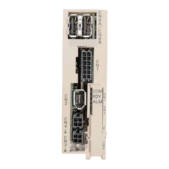
1 Outline DC Power Input Σ-V Series SERVOPACKs The DC Power Input Σ-V Series SERVOPACKs are designed for applications that require frequent high- speed, high-precision positioning. The SERVOPACK makes the most of machine performance in the shortest time possible, thus contributing to improving productivity. Part Names This section describes the part names of SGDV SERVOPACK for MECHATROLINK-II communications ref- erence. -
Page 21: Servopack Ratings And Specifications
1.3 SERVOPACK Ratings and Specifications SERVOPACK Ratings and Specifications This section describes the ratings and specifications of SERVOPACKs. 1.3.1 Ratings Ratings of SERVOPACKs are as shown below. SGDV Continuous Output Current [Arms] Instantaneous Max. Output Current [Arms] 24 VDC 48 VDC 24 VDC 48 VDC Main Circuit Power Supply... -
Page 22: Basic Specifications
1 Outline 1.3.2 Basic Specifications 1.3.2 Basic Specifications Basic specifications of SERVOPACKs are shown below. Drive Method Sine-wave current drive with PWM control Feedback Encoder: 17-bit (incremental/absolute) Surrounding Air 0°C to +55°C Temperature Storage Temperature -20°C to +85°C Ambient Humidity 90% RH or less With no freezing or condensation Storage Humidity... - Page 23 1.3 SERVOPACK Ratings and Specifications (cont’d) Number of 3 ch Channels • Homing deceleration switch (/DEC) Input • External latch (/EXT 1) Sequence Signals • Forward run prohibited (P-OT), reverse run prohibited Input which can (N-OT) Functions be allocated • Forward external torque limit (/P-CL), reverse external torque limit (/N-CL) Signal allocations can be performed, and positive and negative logic can be changed.
-
Page 24: Mechatrolink-Ii Function Specifications
1 Outline 1.3.3 MECHATROLINK-II Function Specifications 1.3.3 MECHATROLINK-II Function Specifications The following table shows the specifications of MECHATROLINK-II. Function Specifications Communication MECHATROLINK-II Protocol 41H to 5FH (Max. number of stations: 30) Station Address Can be selected by the combination of the DIP switch (SW1, SW2). -
Page 25: Servopack Internal Block Diagrams
1.4 SERVOPACK Internal Block Diagrams SERVOPACK Internal Block Diagrams 1.4.1 MECHATROLINK-II Communications Reference (Model: SGDV- E11A) M-II Servomotor Main circuit power supply DC/DC +12.5 V converter (non Voltage -isolated) +5 V sensor Gate drive Current overcurrent protector sensor +5 V DC/DC Control power converter... -
Page 26: Examples Of Servo System Configurations
1 Outline Examples of Servo System Configurations This section describes examples of basic servo system configuration. Connect to the MECHATROLINK-II SGDV- E11A M-II SERVOPACK Power supply Single-phase 100/200 VAC Molded-case circuit breaker (MCCB) Host controller Protects the power I/O signal cable line by shutting the circuit OFF when Encoder cable... -
Page 27: Servopack Model Designation
1.6 SERVOPACK Model Designation SERVOPACK Model Designation This section shows SERVOPACK model designation. 13th 11th + 12th 8th + 9th + 1st + 2nd + 5th + 6th digit digits 10th digits digit digit 3rd digits digits SGDV – 2R9 E 11 A Series 7th digit: Design... -
Page 28: Inspection And Maintenance
• Operation Rate: 20 hours/day max. Note: If the above operating conditions are not used, replacement may be required sooner than the standard replacement period. To extend the life of the parts, reduce the ambient temperature. Contact your Yaskawa representative if you require more-detailed information. -
Page 29: Sigmawin
SigmaWin+ 2.1 SigmaWin+ ..........2-2 2.2 Preparing SigmaWin+ . -
Page 30: Preparing Sigmawin
SigmaWin+ is a software application that can be used to view SERVOPACK status, set parameters, and per- form setup tuning. Preparing SigmaWin+ Install SigmaWin+ after downloading the software application from the following Yaskawa website. http://www.e-mechatronics.com. Connecting a PC with SigmaWin+ A PC with SigmaWin+ installed can be connected to SERVOPACKs by one of two methods. -
Page 31: Starting And Operating The Sigmawin
2.4 Starting and Operating the SigmaWin+ Starting and Operating the SigmaWin+ Use the following procedure to display the main window of the SigmaWin+. Connect a SERVOPACK to a computer which has SigmaWin+ installed. For details, refer to the figure provided in 1.5 Examples of Servo System Configurations. Turn on the SERVOPACK. - Page 32 2 SigmaWin+ Click Search. A message will appear first to indicate that a search is being carried out, and then the search results will be shown in the Connect window. MECHA Note: If the message, "SERVOPACK not found", is shown, refer to the online manual. To view the online manual, refer to 2.3 Connecting a PC with SigmaWin+.
-
Page 33: Parameters (Pn )
2.5 Parameters (Pn Parameters (Pn This section describes the classifications, methods of notation, and settings for parameters given in this man- ual. 2.5.1 Parameter Classification Parameters of the Σ-V Series SERVOPACK are classified into two types of parameters. One type of parame- ters is required for setting up the basic conditions for operation and the other type is required for tuning param- eters that are required to adjust servomotor characteristics. -
Page 34: Setting Parameters
2 SigmaWin+ 2.5.3 Setting Parameters 2.5.3 Setting Parameters There are two ways to set parameters. These are as follows: • Using the Parameter Editing dialog box • Using the Online Parameter Editing dialog box These methods are described below. (1) Using the Parameter Editing Dialog Box In the SigmaWin+ main window, click Parameters - Edit Parameters. - Page 35 2.5 Parameters (Pn Click Edit. The Edit box for the selected parameter will appear. Change the value of the parameter. <For parameters for numeric settings> Enter the value to be set. <For parameters for selecting functions> Click the arrow to open the setting list for each digit and select one item in each list. Click OK.
- Page 36 2 SigmaWin+ 2.5.3 Setting Parameters (2) Using the Online Parameter Editing Dialog Box • Values edited in the Online Parameter Editing dialog box are immediately changed in the SERVOPACK. • If the power to the SERVOPACK is turned OFF or the communication between the SERVOPACK and the SigmaWin+ is interrupted while editing parameters online, the edited values will not be saved in the SERVOPACK.
- Page 37 2.5 Parameters (Pn Click one of the Set buttons located on the right of the parameter list. The Parameters list box will appear. MECHA Select a parameter to edit, and then click OK. The Set Parameters box will appear again. Click OK.
- Page 38 Wiring and Connection 3.1 Main Circuit Wiring ......... . 3-2 3.1.1 Main Circuit Terminals (CN3, CN4) .
-
Page 39: Chapter 3 Wiring And Connection
3 Wiring and Connection 3.1.1 Main Circuit Terminals (CN3, CN4) Main Circuit Wiring The names and specifications of the main circuit terminals are given below. Also this section describes the general precautions for wiring and precautions under special environments. 3.1.1 Main Circuit Terminals (CN3, CN4) M-II : Main circuit terminals... -
Page 40: Main Circuit Wires
3.1 Main Circuit Wiring 3.1.2 Main Circuit Wires Use the following cables for main circuit. These cables are manufactured by YASKAWA Controls Co., Ltd. SERVOPACK Model: SGDV- Terminal Cable Symbols 1R7E 2R9E For power supply L1, L2, C1, C2, JZSP-CF1G00-... -
Page 41: Typical Main Circuit Wiring Examples
3 Wiring and Connection 3.1.3 Typical Main Circuit Wiring Examples 3.1.3 Typical Main Circuit Wiring Examples Note the following points when designing the power ON sequence. • Design the power ON sequence so that main power is turned OFF when a servo alarm signal (ALM) is output. •... -
Page 42: Power Supply Capacities And Power Losses
3.1 Main Circuit Wiring 3.1.4 Power Supply Capacities and Power Losses The following table shows the SERVOPACK’s power supply capacities and power losses. Maximum Main Main Power Supply Control Applicable SERVOPACK Output Circuit Total Circuit Capacity per Circuit Servomotor Model Current Power Power... -
Page 43: Using More Than One Servopack
3 Wiring and Connection 3.1.6 Using More Than One SERVOPACK 3.1.6 Using More Than One SERVOPACK This section shows an example of the wiring and the precautions when more than one SERVOPACK is used. (1) Wiring Example The alarm output (ALM) of each SERVOPACK operates a separate alarm detection relay (1Ry, 2Ry or 3Ry). When the alarm occurs, the ALM output signal transistor is turned OFF. -
Page 44: General Precautions For Wiring
3.1 Main Circuit Wiring 3.1.7 General Precautions for Wiring • Always use a molded-case circuit breaker (1QF) or a fuse to protect the servo system from intersystem faults. • Install a ground fault detector. The SERVOPACK does not have a built-in protective circuit for grounding. To configure a safer system, install a ground fault detector against overloads and short-circuiting, or install a ground fault detector combined with a molded-case circuit breaker. -
Page 45: I/O Signal Connections
3 Wiring and Connection 3.2.1 I/O Signal (CN1) Names and Functions I/O Signal Connections This section describes the names and functions of I/O signals (CN1). Also connection examples by control method are shown. 3.2.1 I/O Signal (CN1) Names and Functions The following table shows the names and functions of I/O signals (CN1). -
Page 46: Example Of I/O Signal Connections
3.2 I/O Signal Connections 3.2.2 Example of I/O Signal Connections The following diagram shows a typical connection example. Photocoupler output Max. operating voltage: 30 VDC Max. output current: 50 mA DC SERVOPACK MECHA Control power supply +24V ∗ 3.3 kΩ +24VIN Servo alarm output for sequence signal... -
Page 47: I/O Signal Allocations
3 Wiring and Connection 3.3.1 Input Signal Allocations I/O Signal Allocations This section describes the I/O signal allocations. 3.3.1 Input Signal Allocations • Inverting the polarity of the forward run prohibited and reverse run prohibited signals from the factory setting will prevent the overtravel function from working in case of sig- nal line disconnections or other failures. - Page 48 3.3 I/O Signal Allocations Connection Not Required CN1 Pin Numbers (SERVOPACK judges Input Signal Names and Validity Input the connection) Parameters Level Signal Always Always Reserve External Torque /N-CL 2 to 6 Limit N-CL B to F Pn50B.3 /DEC 2 to 6 Homing Deceleration LS Pn511.0 B to F...
- Page 49 3 Wiring and Connection 3.3.1 Input Signal Allocations Select Pn50A. If Pn50A cannot be seen in the Parameter Editing dialog box, click the arrows button to view the parameter. Click Edit. The Edit box for Pn50A will appear. 3-12...
- Page 50 3.3 I/O Signal Allocations For the 3rd digit, select 8: Forward run allowed in the P-OT Signal Mapping list. Click OK. The Edit box will close, and Parameter Editing dialog box will appear again. Select Pn50B. If Pn50B cannot be seen in the Parameter Editing dialog box, click the arrows button to view the parameter.
- Page 51 3 Wiring and Connection 3.3.1 Input Signal Allocations Click Edit. The Edit box for Pn50B will appear. For the 2nd digit, select 1: ON when CN1-3 input signal is ON (L-level) in the /P-CL Signal Mapping list. 3-14...
- Page 52 3.3 I/O Signal Allocations Click OK. The Edit box will close, and the Parameter Editing dialog box will appear again. Click Write. The following window will appear after the new parameter setting has been saved in the SERVOPACK. Click OK. To enable the change in the setting, restart the SERVOPACK.
-
Page 53: Output Signal Allocations
3 Wiring and Connection 3.3.2 Output Signal Allocations 3.3.2 Output Signal Allocations • The signals not detected are considered as "Invalid." For example, Positioning Com- pletion (/COIN) signal in speed control is "Invalid." • Inverting the polarity of the brake signal (/BK), i.e. positive logic, will prevent the hold- ing brake from working in case of its signal line disconnection. - Page 54 3.3 I/O Signal Allocations Example of Changing Output Signal Allocations The procedure to set the position completion signal (/COIN) that was previously disabled is allocated to CN1- 10 is shown below. <Parameter Changes> • Pn50E is changed from n.0000 to n.0002. In the SigmaWin+ main window, click Parameters - Edit Parameters.
- Page 55 3 Wiring and Connection 3.3.2 Output Signal Allocations Select Pn50E. If Pn50E cannot be seen in the Parameter Editing dialog box, click the arrows button to view the param- eter. Click Edit. The Edit box for Pn50E will appear. 3-18...
- Page 56 3.3 I/O Signal Allocations For the zero digit, select 2: Outputs the signal from CN1-10 output terminal in the Positioning Completion Signal Mapping (/COIN) list. Click OK. The Edit box will close, and the Parameter Editing dialog box will appear again. Click Write.
-
Page 57: Examples Of Connection To Host Controller
3 Wiring and Connection 3.4.1 Sequence Input Circuit Examples of Connection to Host Controller This section shows examples of SERVOPACK I/O signal connection to the host controller. 3.4.1 Sequence Input Circuit (1) Photocoupler Input Circuit CN1 connector terminals 2, 3, 7, 8 are explained below. The sequence input circuit interface is connected through a relay or open-collector transistor circuit. -
Page 58: Sequence Output Circuit
3.4 Examples of Connection to Host Controller 3.4.2 Sequence Output Circuit The signal output circuit from the SERVOPACK is described below. Incorrect wiring or incorrect voltage application to the output circuit may cause short-cir- cuit. If a short-circuit occurs as a result of any of these causes, the holding brake will not work. -
Page 59: Wiring Mechatrolink-Ii Communications
3 Wiring and Connection Wiring MECHATROLINK-II Communications The following diagram shows an example of connections between a host controller and a SERVOPACK using MECHATROLINK-II communications cables (CN6A, CN6B). 218IF-01 MP2300 YASKAWA STRX M-II STOP INIT TEST CNFG TEST PORT OFF ON... -
Page 60: Encoder Connection
3.6 Encoder Connection Encoder Connection This section describes the encoder signal (CN2) names, functions, and connection examples. 3.6.1 Encoder Signal (CN2) Names and Functions The following table shows the names and functions of encoder signals (CN2). Signal Name Pin No. Function PG 5 V Encoder power supply +5 V... - Page 61 3 Wiring and Connection 3.6.2 Encoder Connection Examples (2) Using as an Absolute Encoder MECHA SERVOPACK Absolute encoder ∗1 Output line-driver SN75ALS174 or the equivalent PG5 V PG0 V ∗2 BAT + ∗2 BAT - Connector Battery shell (Shell) ∗1. : represents shielded twisted-pair wires.
-
Page 62: Noise Control And Measures For Harmonic Suppression
3.7 Noise Control and Measures for Harmonic Suppression Noise Control and Measures for Harmonic Suppression This section describes the wiring for noise control and the DC reactor for harmonic suppression. 3.7.1 Wiring for Noise Control • Because the SERVOPACK is designed as an industrial device, it provides no mecha- nism to prevent noise interference. - Page 63 3 Wiring and Connection 3.7.1 Wiring for Noise Control (1) Noise Filter The SERVOPACK has a built-in microprocessor (CPU), so protect it from external noise as much as possible by installing a noise filter in the appropriate place. The following is an example of wiring for noise control. Non-isolated AC/DC converter SERVOPACK Noise filter...
-
Page 64: Precautions On Connecting Noise Filter
3.7 Noise Control and Measures for Harmonic Suppression 3.7.2 Precautions on Connecting Noise Filter This section describes the precautions on installing a noise filter. (1) Noise Filter Brake Power Supply If using a servomotor with a holding brake, use the following noise filter on the brake power supply input. Model: FN2070-6/07 (Manufactured by SCHAFFNER Electronic.) (2) Precautions on Using Noise Filters Always observe the following installation and wiring instructions. - Page 65 3 Wiring and Connection 3.7.2 Precautions on Connecting Noise Filter Connect the noise filter ground wire directly to the ground plate. Do not connect the noise filter ground wire to other ground wires. Correct Incorrect Noise Noise Filter Filter SERVOPACK SERVOPACK SERVOPACK SERVOPACK Shielded ground wire...
- Page 66 Operation 4.1 MECHATROLINK-II Communications Settings ....4-3 4.1.1 Setting Switches SW1 and SW2 ......... 4-3 4.2 MECHATROLINK-II Commands .
- Page 67 4 Operation 4.8 Other Output Signals ........4-40 4.8.1 Servo Alarm Output Signal (ALM) .
-
Page 68: Mechatrolink-Ii Communications Settings
4.1 MECHATROLINK-II Communications Settings MECHATROLINK-II Communications Settings This section describes the switch settings necessary for MECHATROLINK-II communications. 4.1.1 Setting Switches SW1 and SW2 The SW2 DIP switch is used to make the settings for MECHATROLINK-II communications. The station address is set using the DIP switches (SW1, SW2). M-II SW1 (factory settings) SW2 (factory settings) - Page 69 4 Operation 4.1.1 Setting Switches SW1 and SW2 (2) Setting the Station Address The following table lists the possible settings of the DIP switches (SW1, SW2) that can be combined to form a station address. The factory setting for the station address is 41H (Bit 3 of SW2 = OFF, Bit 1 of SW1 = ON, Bit 2 of SW1 = OFF, Bit 3 of SW1 = OFF, Bit 4 of SW1 = OFF).
-
Page 70: Mechatrolink-Ii Commands
4.2 MECHATROLINK-II Commands MECHATROLINK-II Commands Σ For information on the MECHATROLINK-II commands, refer to -V Series User’s Manual MECHA- TROLINK-II Commands (Manual No.: SIEP S800000 54). Basic Functions Settings This section describes how to set the basic functions for operation. 4.3.1 Servomotor Rotation Direction The servomotor rotation direction can be reversed with parameter Pn000.0 without changing the polarity of the speed/position reference. -
Page 71: Overtravel
4 Operation 4.3.2 Overtravel 4.3.2 Overtravel The overtravel limit function forces movable machine parts to stop if they exceed the allowable range of motion and turn ON a limit switch. For rotating application such as disc table and conveyor, overtravel function is not necessary. In such a case, no wiring for overtravel input signals is required. - Page 72 4.3 Basic Functions Settings (2) Overtravel Function Setting Parameters Pn50A and Pn50B can be set to enable or disable the overtravel function. If the overtravel function is not used, no wiring for overtravel input signals will be required. When Parameter Meaning Classification Enabled...
- Page 73 4 Operation 4.3.2 Overtravel (4) Overtravel Warning Function This function detects an overtravel warning (A.9A0) if overtravel occurs while the servomotor power is ON. Using this function enables notifying the host controller when the SERVOPACK detects overtravel even if the overtravel signal is ON only momentarily.
-
Page 74: Software Limit Settings
4.3 Basic Functions Settings 4.3.3 Software Limit Settings The software limits set limits in software for machine movement that do not use the overtravel signals (P-OT and N-OT). If a software limit is exceeded, an emergency stop will be executed in the same way as it is for overtravel. -
Page 75: Holding Brakes
4 Operation 4.3.4 Holding Brakes 4.3.4 Holding Brakes A holding brake is a brake used to hold the position of the movable part of the machine when the SERVO- PACK is turned OFF so that movable part does not move due to gravity or external forces. Holding brakes are built into servomotors with brakes. - Page 76 4.3 Basic Functions Settings (1) Wiring Example Use the brake signal (/BK) and the brake power supply to form a brake ON/OFF circuit. The following dia- gram shows a standard wiring example. The timing can be easily set using the brake signal (/BK). Servomotor Non-isolated with holding...
- Page 77 4 Operation 4.3.4 Holding Brakes (2) Brake Signal (/BK) Setting This output signal controls the brake. The allocation of the /BK signal can be changed. Refer to (3) Brake Sig- nal (/BK) Allocation for allocation. The /BK signal turns OFF (applies the brake) when an alarm is detected or the SV_OFF command is received. The brake OFF timing can be adjusted with Pn506.
- Page 78 4.3 Basic Functions Settings (4) Brake ON Timing after the Servomotor Stops When the servomotor stops, the /BK signal turns OFF at the same time as the SV_OFF command is received. Use parameter Pn506 to change the timing to turn OFF the servomotor power after the SV_OFF command has been received.
- Page 79 4 Operation 4.3.4 Holding Brakes (5) Brake Signal (/BK) Output Timing during Servomotor Rotation If an alarm occurs while the servomotor is rotating, the servomotor will come to a stop and the brake signal (/BK) will be turned OFF. The timing of brake signal (/BK) output can be adjusted by setting the brake refer- ence output speed level (Pn507) and the waiting time for brake signal when motor running (Pn508).
-
Page 80: Stopping Servomotors After Sv_Off Command Or Alarm Occurrence
4.3 Basic Functions Settings 4.3.5 Stopping Servomotors after SV_OFF Command or Alarm Occurrence The servomotor stopping method can be selected after the SV_OFF command is received or an alarm occurs. • The elements in the SERVOPACK will deteriorate if turning the power supply ON and OFF or starting and stopping the servomotor during the servo ON status while there is a reference input. -
Page 81: Setting Motor Overload Detection Level
4 Operation 4.3.6 Setting Motor Overload Detection Level 4.3.6 Setting Motor Overload Detection Level In this SERVOPACK, the detection timing of the warnings and alarms can be changed by changing how to detect an overload warning (A.910) and overload (low load) alarm (A.720). The overload characteristics and the detection level of the overload (high load) alarm (A.710) cannot be changed. - Page 82 4.3 Basic Functions Settings (2) Changing Detection Timing of Overload (Low Load) Alarm (A.720) An overload (low load) alarm (A.720) can be detected earlier to protect the servomotor from overloading. The time required to detect an overload alarm can be shortened by using the derated motor base current obtained with the following equation.
-
Page 83: Trial Operation
4 Operation 4.4.1 Inspection and Checking before Trial Operation Trial Operation This section describes a trial operation using MECHATROLINK-II communications. 4.4.1 Inspection and Checking before Trial Operation To ensure safe and correct trial operation, inspect and check the following items before starting trial operation. (1) Servomotors Inspect and check the following items, and take appropriate measures before performing trial operation if any problem exists. -
Page 84: Trial Operation Via Mechatrolink-Ii
4.4 Trial Operation 4.4.2 Trial Operation via MECHATROLINK-II The following table provides the procedures for trial operation via MECHATROLINK-II. Step Description Reference Confirm that the wiring is correct, and then connect the I/O signal con- 3 Wiring and Connection nector (CN1 connector). Turn ON the power to the SERVOPACK. -
Page 85: Electronic Gear
4 Operation 4.4.3 Electronic Gear 4.4.3 Electronic Gear The electronic gear enables the workpiece travel distance per reference unit input from the host controller. The minimum unit of the position data moving a load is called a reference unit. The section indicates the difference between using and not using an electronic gear when a workpiece is moved 10 mm in the following configuration. - Page 86 4.4 Trial Operation (1) Electronic Gear Ratio Set the electronic gear ratio using Pn20E and Pn210. Electronic Gear Ratio (Numerator) Position Classification Pn20E Setting Range Setting Unit Factory Setting When Enabled 1 to 1073741824 After restart Setup Electronic Gear Ratio (Denominator) Position Classification Pn210...
-
Page 87: Test Without Motor Function
4 Operation 4.5.1 Motor Information Test Without Motor Function The test without a motor is used to check the operation of the host controller and peripheral devices by simu- lating the operation of the servomotor in the SERVOPACK, i.e., without actually operating a servomotor. This function enables you to check wiring, verify the system while debugging, and verify parameters, thus shorten- ing the time required for setup work and preventing damage to the machine that may result from possible mal- functions. -
Page 88: Motor Position And Speed Responses
4.5 Test Without Motor Function 4.5.2 Motor Position and Speed Responses For the test without a motor, the following responses are simulated for references from the host controller according to the gain settings for position or speed control. • Servomotor position •... -
Page 89: Limitations
4 Operation 4.5.3 Limitations 4.5.3 Limitations The following functions cannot be used during the test without a motor. • Brake output signal (The brake output signal can be checked with the I/O signal monitor function of the Sig- maWin+.) • Items marked with "×" in the following utility function table. Can be used or not Fn No. -
Page 90: Limiting Torque
4.6 Limiting Torque Limiting Torque The SERVOPACK provides the following four methods for limiting output torque to protect the machine. Reference Limiting Method Description Section Always limits torque by setting the parameter. 4.6.1 Internal torque limit Limits torque by input signal from the host controller. 4.6.2 External torque limit Torque limit with P_TLIM,... -
Page 91: External Torque Limit
4 Operation 4.6.2 External Torque Limit 4.6.2 External Torque Limit Use this function to limit torque by inputting a signal from the host controller at specific times during machine operation. For example, some pressure must continually be applied (but not enough to damage the workpiece) when the robot is holding a workpiece or when a device is stopping on contact. -
Page 92: Checking Output Torque Limiting During Operation
4.6 Limiting Torque (3) Changes in Output Torque during External Torque Limiting The following diagrams show the change in output torque when the internal torque limit is set to 800%. In this example, the servomotor rotation direction is Pn000.0 = 0 (Sets CCW as forward direction). /P-CL Pn402 Pn402... -
Page 93: Absolute Encoders
4 Operation 4.7.1 Connecting the Absolute Encoder Absolute Encoders If using an absolute encoder, a system to detect the absolute position can be designed for use with the host controller. As a result, an operation can be performed without a zero point return operation immediately after the power is turned ON. -
Page 94: Absolute Data Request (Sens On Command)
4.7 Absolute Encoders 4.7.2 Absolute Data Request (SENS ON Command) The Turn Encoder Power Supply ON command (SENS_ON) must be sent to obtain absolute data as an output from the SERVOPACK. The SENS_ON command is sent at the following timing. M-II SERVOPACK control 5 seconds max. -
Page 95: Battery Replacement
4 Operation 4.7.3 Battery Replacement 4.7.3 Battery Replacement If the battery voltage drops to approximately 2.7 V or less, an absolute encoder battery error alarm (A.830) or an absolute encoder battery error warning (A.930) will be displayed. If this alarm or warning is displayed, replace the batteries using the following procedure. Use Pn008.0 to set either an alarm (A.830) or a warning (A.930). - Page 96 4.7 Absolute Encoders (1) Battery Replacement Procedure 1. Turn ON the control power supply of the SERVOPACK only. 2. Open the battery case cover. Open the cover. 3. Remove the old battery and mount the new JZSP-BA01 battery as shown below. To the SERVOPACK Encoder Cable Mount the JZSP-BA01 battery.
-
Page 97: Absolute Encoder Setup
4 Operation 4.7.4 Absolute Encoder Setup 4.7.4 Absolute Encoder Setup CAUTION • The rotational data will be a value between -2 and +2 rotations when the absolute encoder setup is exe- cuted. The reference position of the machine system will change. Set the reference position of the host controller to the position after setup. - Page 98 4.7 Absolute Encoders Click Continue. The Absolute encoder Setup box will appear. The Alarm Name box displays the code and name of the alarm that is occurring now. Click Execute setting. A verification message will appear confirming if you want to continue although the coordinate system will change.
- Page 99 4 Operation 4.7.4 Absolute Encoder Setup Click OK to return to the main window. To perform an origin search, restart the SERVOPACK. 4-34...
-
Page 100: Multiturn Limit Setting
4.7 Absolute Encoders 4.7.5 Multiturn Limit Setting The multiturn limit setting is used in position control applications for a turntable or other rotating device. For example, consider a machine that moves the turntable in the following diagram in only one direction. Turntable Gear Servomotor... -
Page 101: Multiturn Limit Disagreement Alarm (A.cc0)
4 Operation 4.7.6 Multiturn Limit Disagreement Alarm (A.CC0) Set the value, the desired rotational amount -1, to Pn205. Factory Setting (= 65535) Other Setting (≠65535) +32767 Reverse Pn205 setting value Forward Forward Reverse Rotational data Rotational data Motor rotations Motor rotations -32768 4.7.6 Multiturn Limit Disagreement Alarm (A.CC0) - Page 102 4.7 Absolute Encoders Click Continue. The Multi-Turn Limit Setting box will appear. Change the setting to the desired number of revolutions. To save the settings, click Writing into the Servopack. A warning message will appear. Click OK and the settings are changed to the new ones. Restart the SERVOPACK.
- Page 103 4 Operation 4.7.6 Multiturn Limit Disagreement Alarm (A.CC0) Return to the SigmaWin+ main window. To make the settings for the servomotor, click Setup – Multi-Turn Limit Setting again. A verification message will appear confirming if you want to continue although the position data will change.
-
Page 104: Absolute Encoder Origin Offset
4.7 Absolute Encoders 4.7.7 Absolute Encoder Origin Offset If using the absolute encoder, the positions of the encoder and the offset of the machine coordinate system (APOS) can be set. Use Pn808 to make the setting. After the SENS_ON command is received by MECHA- TROLINK communications, this parameter will be enabled. -
Page 105: Other Output Signals
4 Operation 4.8.1 Servo Alarm Output Signal (ALM) Other Output Signals This section explains other output signals. Use these signals according to the application needs, e.g., for machine protection. 4.8.1 Servo Alarm Output Signal (ALM) This section describes signals that are output when the SERVOPACK detects errors and resetting methods. (1) Servo Alarm Output Signal (ALM) This signal is output when the SERVOPACK detects an error. -
Page 106: Rotation Detection Output Signal (/Tgon)
4.8 Other Output Signals 4.8.3 Rotation Detection Output Signal (/TGON) This output signal indicates that the servomotor is rotating at the speed set for Pn502 or a higher speed. (1) Signal Specifications Signal Connector Pin Type Setting Meaning Name Number Servomotor is rotating with the motor speed above ON (closed) the setting in Pn502. -
Page 107: Speed Coincidence Output Signal (/V-Cmp)
4 Operation 4.8.5 Speed Coincidence Output Signal (/V-CMP) 4.8.5 Speed Coincidence Output Signal (/V-CMP) The speed coincidence output signal (/V-CMP) is output when the actual servomotor speed is the same as the reference speed. The host controller uses the signal as an interlock. This signal is the output signal during speed control. -
Page 108: Positioning Completed Output Signal (/Coin)
4.8 Other Output Signals 4.8.6 Positioning Completed Output Signal (/COIN) This signal indicates that servomotor movement has been completed during position control. When the difference between the number of references output by the host controller and the travel distance of the servomotor (position error) drops below the set value in the parameter, the positioning completion signal will be output. -
Page 109: Positioning Near Output Signal (/Near)
4 Operation 4.8.7 Positioning Near Output Signal (/NEAR) 4.8.7 Positioning Near Output Signal (/NEAR) Before confirming that the positioning completed signal has been received, the host controller first receives a positioning near signal and can prepare the operating sequence after positioning has been completed. The time required for this sequence after positioning can be shortened. - Page 110 4.8 Other Output Signals (1) Signals Output during Servomotor Speed Limit The following signal is output when the motor speed reaches the limit speed. Signal Connector Type Setting Meaning Name Pin Number ON (closed) Servomotor speed limit being applied. Output /VLT Must be allocated OFF (open)
- Page 111 Adjustments 5.1 Type of Adjustments and Basic Adjustment Procedure ....5-3 5.1.1 Adjustments ............5-3 5.1.2 Basic Adjustment Procedure .
- Page 112 5 Adjustments 5.8 Additional Adjustment Function ....... 5-71 5.8.1 Switching Gain Settings ..........5-71 5.8.2 Manual Adjustment of Friction Compensation .
-
Page 113: Chapter 5 Adjustments
5.1 Type of Adjustments and Basic Adjustment Procedure Type of Adjustments and Basic Adjustment Procedure This section describes type of adjustments and the basic adjustment procedure. 5.1.1 Adjustments Adjustments (tuning) are performed to optimize the responsiveness of the SERVOPACK. The responsiveness is determined by the servo gain that is set in the SERVOPACK. The servo gain is set using a combination of parameters, such as speed loop gain, position loop gain, filters, friction compensation, and moment of inertia ratio. -
Page 114: Basic Adjustment Procedure
5 Adjustments 5.1.2 Basic Adjustment Procedure 5.1.2 Basic Adjustment Procedure The basic adjustment procedure is shown in the following flowchart. Make suitable adjustments considering the conditions and operating requirements of the machine. Start adjusting servo gain. (1) Adjust using Tuning-less Function. Runs the servomotor without any adjustments. -
Page 115: Monitoring Operation During Adjustment
5.1 Type of Adjustments and Basic Adjustment Procedure 5.1.3 Monitoring Operation during Adjustment While adjusting the servo gain, always monitor the operating status of the machine and the signal waveform. Connect a measurement instrument, such as a memory recorder, to the SERVOPACK to monitor the signal waveform. - Page 116 5 Adjustments 5.1.3 Monitoring Operation during Adjustment The following signals can be monitored by selecting functions with parameters Pn006 and Pn007. Pn006 is used for analog monitor 1 and Pn007 is used for analog monitor 2. Description Parameter Monitor Signal Unit Remarks [Pn007...
- Page 117 5.1 Type of Adjustments and Basic Adjustment Procedure (3) Setting Monitor Factor The output voltages on analog monitors 1 and 2 are calculated by the following equations. × × Analog monitor 1 output voltage = (-1) Signal selection Multiplier + Offset voltage [V] (Pn006=n.00 ) (Pn552) (Pn550)
-
Page 118: Safety Precautions On Adjustment Of Servo Gains
5 Adjustments 5.1.4 Safety Precautions on Adjustment of Servo Gains 5.1.4 Safety Precautions on Adjustment of Servo Gains CAUTION • If adjusting the servo gains, observe the following precautions. • Do not touch the rotating section of the servomotor while power is being supplied to the motor. •... - Page 119 5.1 Type of Adjustments and Basic Adjustment Procedure Under these conditions, the following equation is used to calculate the maximum limit (Pn520). 6000 131072 Pn520 = × × × 2 400/10 327680 × 2 655360 If the acceleration/deceleration of the position reference exceeds the capacity of the servomotor, the servomo- tor cannot perform at the requested speed, and the allowable level for position error will be increased as not to satisfy these equations.
- Page 120 5 Adjustments 5.1.4 Safety Precautions on Adjustment of Servo Gains Related Alarms Alarm Alarm Name Meaning Display This alarm occurs if the servomotor power is turned ON when the position Position Error Overflow A.d01 error is greater than the set value of Pn526 while the servomotor power is Alarm at Servo ON OFF.
-
Page 121: Tuning-Less Function
5.2 Tuning-less Function Tuning-less Function The tuning-less function is enabled in the factory settings. If resonance is generated or excessive vibration occurs, refer to 5.2.2 Tuning-less Levels Setting (Fn200) Procedure and change the set value of Pn170.2 for the rigidity level and the set value in Pn170.3 for the load level. CAUTION •... - Page 122 5 Adjustments 5.2.1 Tuning-less Function (cont’d) Function Availability Remarks Disable the tuning-less function by setting Offline moment of inertia calculation * Not available Pn170.0 to 0 before executing this function. While this function is being used, the tuning- Mechanical analysis* Available less function cannot be used.
-
Page 123: Tuning-Less Levels Setting (Fn200) Procedure
5.2 Tuning-less Function 5.2.2 Tuning-less Levels Setting (Fn200) Procedure CAUTION • To ensure safety, perform the tuning-less function in a state where the SERVOPACK can come to an emergency stop at any time. The procedure to use the tuning-less function is given below. The SigmaWin+ is required to execute this function. - Page 124 5 Adjustments 5.2.2 Tuning-less Levels Setting (Fn200) Procedure Select Pn170 in the Parameter Editing dialog box. If Pn170 cannot be seen in the Parameter Editing dialog box, click the arrows to view the parameter. Click Edit. The Edit box for Pn170 will appear. 5-14...
- Page 125 5.2 Tuning-less Function For 3rd digit, select one of the load levels in the Tuning-less Load Level list. • If the response waveform results in overshooting or if the load moment of inertia exceeds the allowable level, select 2: Tuning-less Load Level 2. (If any damage caused when the load moment of inertia exceeds the allowable level, these conditions are regarded as being outside the scope of the warranty.) •...
- Page 126 5 Adjustments 5.2.2 Tuning-less Levels Setting (Fn200) Procedure (3) Alarm and Corrective Actions The autotuning alarm (A.521) will occur if resonance sound is generated or excessive vibration occurs during position control. In such case, take the following actions. • Increase the setting of Pn170.3 or reduce the setting of Pn170.2. Parameters Disabled by Tuning-less Function When the tuning-less function is enabled in the factory settings, the settings of these parameters are not avail- able: Pn100, Pn101, Pn102, Pn103, Pn104, Pn105, Pn106, Pn160, Pn139, and Pn408.
-
Page 127: Related Parameters
5.2 Tuning-less Function 5.2.3 Related Parameters The following table lists parameters related to this function and their possibility of being changed while exe- cuting this function or of being changed automatically after executing this function. • Parameters related to this function These are parameters that are used or referenced when executing this function. -
Page 128: Advanced Autotuning (Fn201)
5 Adjustments 5.3.1 Advanced Autotuning Advanced Autotuning (Fn201) This section describes the adjustment using advanced autotuning. • Advanced autotuning starts adjustments based on the set speed loop gain (Pn100). Therefore, precise adjustments cannot be made if there is vibration when starting adjustments. - Page 129 5.3 Advanced Autotuning (Fn201) Advanced autotuning performs the following adjustments. • Moment of inertia ratio • Gains (e.g., position loop gain and speed loop gain) • Filters (torque reference filter and notch filter) • Friction compensation • Anti-resonance control • Vibration suppression (Mode = 2 or 3) Refer to 5.3.3 Related Parameters for parameters used for adjustments.
- Page 130 5 Adjustments 5.3.1 Advanced Autotuning (3) When Advanced Autotuning Cannot Be Performed Successfully Advanced autotuning cannot be performed successfully under the following conditions. Refer to 5.4 Advanced Autotuning by Reference (Fn202) and 5.5 One-parameter Tuning (Fn203) for details. • The operating range is not applicable. •...
-
Page 131: Advanced Autotuning Procedure
5.3 Advanced Autotuning (Fn201) 5.3.2 Advanced Autotuning Procedure The following procedure is used for advanced autotuning. The SigmaWin+ is required to execute this function. CAUTION • When using the SERVOPACK with Jcalc = OFF (load moment of inertia is not calculated), be sure to set a suitable value for the moment of inertia ratio (Pn103). - Page 132 5 Adjustments 5.3.2 Advanced Autotuning Procedure In the SigmaWin+ main window, click Tuning – Tuning. MECHA Click Cancel to return to the SigmaWin+ main window without executing tuning. Click Execute. The following window will appear. MECHA 5-22...
- Page 133 5.3 Advanced Autotuning (Fn201) Click Execute. The following window will appear. MECHA Speed Loop Setting Set the speed loop gain and integral time constant. If the response of the speed loop is poor, the moment of inertia (mass) ratio cannot be measured accu- rately.
- Page 134 5 Adjustments 5.3.2 Advanced Autotuning Procedure Confirm Click Confirm to view the driving pattern. MECHA Detailed Setting Create the reference pattern for setting the moment of inertia (mass) by changing the values with the slider or by directly entering the values. Next Click Next to view the Reference Transmission box.
- Page 135 5.3 Advanced Autotuning (Fn201) Next The Next button is available if the data is transferred successfully. If an error occurs or if the transmis- sion is interrupted, it is unavailable and cannot be selected. Click Next to view the Operation/Measurement box. Cancel Click Cancel to stop processing and return to the main window.
- Page 136 5 Adjustments 5.3.2 Advanced Autotuning Procedure Repeat steps 7 through 9 until all the measurements have been taken. Measurements will be made from two to seven times and then verification will be performed. The actual number of times the measurements have been taken is displayed in the upper left part on the screen. The progress bar displays the percentage of data that has been transferred.
- Page 137 5.3 Advanced Autotuning (Fn201) After confirming that the value displayed in the identified moment of inertia (mass) ratio and the value displayed in the Pn103: Moment of Inertia Ratio are the same, click Finish. The following window will appear. MECHA Click OK.
- Page 138 5 Adjustments 5.3.2 Advanced Autotuning Procedure Select whether or not to use the load moment of inertia (load mass) identification from the Switching the load moment of inertia (load mass) identification box, the mode from the Mode selection box, the mechanism from the Mechanism selection box, and enter the moving distance.
- Page 139 5.3 Advanced Autotuning (Fn201) After confirming the safety of the area adjoining the drive unit, click Yes. The motor will start rotating and tuning will start. MECHA Vibration generated during tuning is automatically detected, and the optimum setting for the detected vibration will be made.
- Page 140 5 Adjustments 5.3.2 Advanced Autotuning Procedure (2) Failure in Operation When Operation Cannot be Performed Probable Cause Corrective Actions The main circuit power supply was OFF. Turn ON the main circuit power supply. An alarm or warning occurred. Remove the cause of the alarm or the warning. Overtraveling occurred.
- Page 141 5.3 Advanced Autotuning (Fn201) Related Functions on Advanced Autotuning This section describes functions related to advanced tuning. Notch Filter Usually, set this function to Auto Setting. (The notch filter is factory-set to Auto Setting.) If this function is set to Auto Setting, vibration will be detected automatically during advanced autotuning and the notch filter will be set.
- Page 142 5 Adjustments 5.3.2 Advanced Autotuning Procedure Friction Compensation This function compensates for changes in the following conditions. • Changes in the viscous resistance of the lubricant, such as the grease, on the sliding parts of the machine • Changes in the friction resistance resulting from variations in the machine assembly •...
-
Page 143: Related Parameters
5.3 Advanced Autotuning (Fn201) 5.3.3 Related Parameters The following table lists parameters related to this function and their possibility of being changed while exe- cuting this function or of being changed automatically after executing this function. • Parameters related to this function These are parameters that are used or referenced when executing this function. -
Page 144: Advanced Autotuning By Reference (Fn202)
5 Adjustments 5.4.1 Advanced Autotuning by Reference Advanced Autotuning by Reference (Fn202) Adjustments with advanced autotuning by reference are described below. • Advanced autotuning by reference starts adjustments based on the set speed loop gain (Pn100). Therefore, precise adjustments cannot be made if there is vibration when starting adjustments. - Page 145 5.4 Advanced Autotuning by Reference (Fn202) (1) Preparation The following conditions must be met to perform advanced autotuning by reference. • The SERVOPACK must be in Servo Ready status (Refer to 4.8.4). • There must be no overtravel. • The servomotor power must be OFF. •...
-
Page 146: Advanced Autotuning By Reference Procedure
5 Adjustments 5.4.2 Advanced Autotuning by Reference Procedure 5.4.2 Advanced Autotuning by Reference Procedure The following procedure is used for advanced autotuning by reference. The SigmaWin+ is required to execute this function. CAUTION • When using the MP2000 Series with phase control, select the mode = 1 (standard level). If 2 or 3 is selected, phase control of the MP2000 Series may not be possible. - Page 147 5.4 Advanced Autotuning by Reference (Fn202) Click OK. The following window will appear. MECHA Select the Position reference input option under Reference input from host controller in the Tuning main window, and then click Autotuning. The following window will appear. MECHA 5-37...
- Page 148 5 Adjustments 5.4.2 Advanced Autotuning by Reference Procedure Select the mode from the Mode selection combo box and the mechanism from Mechanism selection combo box, and then click Next. When the Start tuning using the default settings. check box is selected in the Autotuning-Setting Con- ditions box, tuning will be executed using tuning parameters set to the default value.
- Page 149 5.4 Advanced Autotuning by Reference (Fn202) Turn the servo on and then input the reference from the host controller. Click Start tuning. MECHA After confirming the safety of the area adjoining the drive unit, click Yes. The motor will start rotating and tuning will start. MECHA Vibration generated during tuning is automatically detected, and the optimum setting for the detected vibration will be made.
- Page 150 5 Adjustments 5.4.2 Advanced Autotuning by Reference Procedure (2) Failure in Operation When Operation Cannot be Performed Probable Cause Corrective Actions The main circuit power supply was OFF. Turn ON the main circuit power supply. An alarm or warning occurred. Remove the cause of the alarm or the warning.
- Page 151 5.4 Advanced Autotuning by Reference (Fn202) Vibration Suppression The vibration suppression function suppresses transitional vibration at frequency as low as 1 to 100 Hz that is generated mainly when positioning if the machine stand vibrates. Usually, set this function to Auto Setting. (The vibration suppression function is factory-set to Auto Setting.) When this function is set to Auto Setting, vibration will be automatically detected during advanced autotuning by reference and vibration suppression will be automatically adjusted and set.
-
Page 152: Related Parameters
5 Adjustments 5.4.3 Related Parameters 5.4.3 Related Parameters The following table lists parameters related to this function and their possibility of being changed while exe- cuting this function or of being changed automatically after executing this function. • Parameters related to this function These are parameters that are used or referenced when executing this function. -
Page 153: One-Parameter Tuning (Fn203)
5.5 One-parameter Tuning (Fn203) One-parameter Tuning (Fn203) Adjustments with one-parameter tuning are described below. 5.5.1 One-parameter Tuning One-parameter tuning is used to manually make tuning level adjustments during operation with a position ref- erence or speed reference input from the host controller. One-parameter tuning enables automatically setting related servo gain settings to balanced conditions by adjusting one or two tuning levels. - Page 154 5 Adjustments 5.5.2 One-parameter Tuning Procedure (1) Operating Procedure WARNING Be sure to carefully read the SigmaWin+ Operation Manual before executing this function. Special care must be taken for the following. • Before executing this function, make sure that the emergency stop (power off) can be activated when needed.
- Page 155 5.5 One-parameter Tuning (Fn203) Click Execute. The following window will appear. MECHA <Supplement> If the following window will appear, click OK and confirm that the correct moment of inertia ratio in Pn103 is set by using the Moment of Inertia (Mass) Setting window. MECHA Click Advanced adjustment.
- Page 156 5 Adjustments 5.5.2 One-parameter Tuning Procedure Click Custom tuning. The following box will appear. MECHA The tuning modes that can be selected will vary according to the SERVOPACK setting. Select the tuning mode from the Tuning mode box and the mechanism from the Mechanism selection box, and then click Next.
- Page 157 5.5 One-parameter Tuning (Fn203) Enter the correct moment of inertia ratio and then click Next. The following window will appear. MECHA Turn the servo on and then input the reference from the host controller. Click Start tuning. MECHA 5-47...
- Page 158 5 Adjustments 5.5.2 One-parameter Tuning Procedure Change the tuning level by clicking the setting arrows. Continue to raise the level until an overshoot occurs. Note: The set feedforward level will not be applied until the Positioning Completion signal (/COIN) is output. The notch filter/anti-resonance control auto setting function, the anti-resonance control adjustment func- tion, or autotuning with reference input can be used as required.
- Page 159 5.5 One-parameter Tuning (Fn203) Functions To Suppress Vibration • <Notch Filter/Anti-resonance Control Adjustment Auto Setting Function> For vibration frequencies above 1,000 Hz when servo gains are increased, the notch filter auto setting function provides effective suppression. For vibration frequencies between 100 and 1,000 Hz, the anti-resonance con- trol adjustment auto setting function is effective.
- Page 160 5 Adjustments 5.5.2 One-parameter Tuning Procedure (2) Related Functions on One-parameter Tuning This section describes functions related to one-parameter tuning. Notch Filter Usually, set this function to Auto Setting. (The notch filter is factory-set to Auto Setting.) If this function is set to Auto Setting, vibration will be detected automatically during one-parameter tuning and the notch filter will be set.
- Page 161 5.5 One-parameter Tuning (Fn203) Feedforward If Pn140 is set to the factory setting and the tuning mode setting is changed to 2 or 3, the feedforward gain (Pn109), speed feedforward (VFF) input, and torque feedforward (TFF) input will be disabled. Set Pn140.3 to 1 if model following control is used together with the speed feedforward (VFF) input and torque feedforward (TFF) input from the host controller.
-
Page 162: One-Parameter Tuning Example
5 Adjustments 5.5.3 One-parameter Tuning Example 5.5.3 One-parameter Tuning Example The following procedure is used for one-parameter tuning on the condition that the tuning mode is set to 2 or 3. This mode is used to reduce positioning time. Step Measuring Instrument Display Example Operation Position error... -
Page 163: Related Parameters
5.5 One-parameter Tuning (Fn203) 5.5.4 Related Parameters The following table lists parameters related to this function and their possibility of being changed while exe- cuting this function or of being changed automatically after executing this function. • Parameters related to this function These are parameters that are used or referenced when executing this function. -
Page 164: Anti-Resonance Control Adjustment Function (Fn204)
5 Adjustments 5.6.1 Anti-Resonance Control Adjustment Function Anti-Resonance Control Adjustment Function (Fn204) This section describes the anti-resonance control adjustment function. 5.6.1 Anti-Resonance Control Adjustment Function The anti-resonance control adjustment function increases the effectiveness of the vibration suppression after one-parameter tuning. This function is effective in supporting anti-resonance control adjustment if the vibra- tion frequencies are from 100 to 1000 Hz. -
Page 165: Anti-Resonance Control Adjustment Function Operating Procedure
5.6 Anti-Resonance Control Adjustment Function (Fn204) 5.6.2 Anti-Resonance Control Adjustment Function Operating Procedure With this function, an operation reference is sent, and the function is executed while vibration is occurring. The SigmaWin+ is required to execute this function. The following methods can be used for the anti-resonance control adjustment function. •... - Page 166 5 Adjustments 5.6.2 Anti-Resonance Control Adjustment Function Operating Procedure (1) With Undetermined Vibration Frequency In the SigmaWin+ main window, click Tuning - Tuning. MECH Click Cancel to return to the SigmaWin+ main window without executing tuning. Click Execute. The following window will appear. MECHA 5-56...
- Page 167 5.6 Anti-Resonance Control Adjustment Function (Fn204) Click Advanced adjustment. The following box will appear. MECHA Click Custom tuning. The following box will appear. MECHA Select the tuning mode from the Tuning mode box and the mechanism from the Mechanism selection box, and then click Next. The following box will appear.
- Page 168 5 Adjustments 5.6.2 Anti-Resonance Control Adjustment Function Operating Procedure Enter the correct moment of inertia ratio and then click Next. The following window will appear. MECHA Click Anti-res Ctrl Adj. The following window will appear. MECHA Click Auto Detect to set the frequency and click Start adjustment. The following window will appear.
- Page 169 5.6 Anti-Resonance Control Adjustment Function (Fn204) Adjust the damping gain by clicking the setting arrows. MECHA Click Reset to reset the settings to their original values during adjustment. When the adjustment is complete, click Finish to return to the main window. The set values will be written in the SERVOPACK.
- Page 170 5 Adjustments 5.6.2 Anti-Resonance Control Adjustment Function Operating Procedure Click Execute. The following window will appear. MECHA Click Advanced adjustment. The following box will appear. MECHA Click Custom tuning. The following box will appear. MECHA 5-60...
- Page 171 5.6 Anti-Resonance Control Adjustment Function (Fn204) Select the tuning mode from the Tuning mode box and the mechanism from the Mechanism selection box, and then click Next. The following box will appear. MECHA Enter the correct moment of inertia ratio and then click Next. The following window will appear.
- Page 172 5 Adjustments 5.6.2 Anti-Resonance Control Adjustment Function Operating Procedure Click Manual Set to set the frequency and click Start adjustment. The following window will appear. MECHA Adjust the frequency by clicking the setting arrows. MECHA Click Reset to reset the settings to their original values during adjustment. Adjust the damping gain by clicking the setting arrows.
-
Page 173: Related Parameters
5.6 Anti-Resonance Control Adjustment Function (Fn204) 5.6.3 Related Parameters The following table lists parameters related to this function and their possibility of being changed while exe- cuting this function or of being changed automatically after executing this function. • Parameters related to this function These are parameters that are used or referenced when executing this function. -
Page 174: Vibration Suppression Function (Fn205)
5 Adjustments 5.7.1 Vibration Suppression Function Vibration Suppression Function (Fn205) The vibration suppression function is described in this section. 5.7.1 Vibration Suppression Function The vibration suppression function suppresses transitional vibration at frequency as low as 1 to 100 Hz that is generated mainly when positioning if the machine stand vibrates. -
Page 175: Vibration Suppression Function Operating Procedure
5.7 Vibration Suppression Function (Fn205) (3) Detection of Vibration Frequencies No frequency detection may be possible if the vibration does not appear as a position error or the vibration resulting from the position error is too small. The detection sensitivity can be adjusted by changing the setting for the remained vibration detection width (Pn560) which is set as a percentage of the positioning completed width (Pn522). - Page 176 5 Adjustments 5.7.2 Vibration Suppression Function Operating Procedure Click Execute. The following window will appear. MECHA Click Advanced adjustment. The following box will appear. MECHA Click Custom tuning. The following box will appear. MECHA 5-66...
- Page 177 5.7 Vibration Suppression Function (Fn205) Select the 2 or 3 of tuning mode from the Tuning mode box and the mechanism from the Mechanism selection box, and then click Next. The following box will appear. Click Vib Suppress. The Vibration suppression Function box will appear. MECH 5-67...
- Page 178 5 Adjustments 5.7.2 Vibration Suppression Function Operating Procedure Set a frequency by using the Import function or by manually selecting the frequency. Click Import. The value of the residual vibration frequency being monitored will be imported to the Set frequency box. This function, however, is effective only when the residual vibration frequency is between 1.0 and 100.0.
- Page 179 5.7 Vibration Suppression Function (Fn205) After the vibration has been successfully suppressed, click Finish. The value of the Set frequency will be transferred to and saved in the SERVOPACK. No settings related to the vibration suppression function will be changed during opera- tion.
-
Page 180: Related Parameters
5 Adjustments 5.7.3 Related Parameters 5.7.3 Related Parameters The following table lists parameters related to this function and their possibility of being changed while exe- cuting this function or of being changed automatically after executing this function. • Parameters related to this function These are parameters that are used or referenced when executing this function. -
Page 181: Additional Adjustment Function
5.8 Additional Adjustment Function Additional Adjustment Function This section describes the functions that can be used for additional fine tuning after making adjustments with advanced autotuning, advanced autotuning by reference, or one-parameter tuning. • Switching gain settings • Friction compensation •... - Page 182 5 Adjustments 5.8.1 Switching Gain Settings (2) Manual Gain Switching Manual gain switching uses G-SEL of OPTION field to switch between gain setting 1 and gain setting 2. Type Command Name Setting Meaning Switches to gain setting 1. Input G-SEL of OPTION field Switches to gain setting 2.
- Page 183 5.8 Additional Adjustment Function Relationship between the Waiting and Switching Times for Gain Switching In this example, the "positioning completed signal (/COIN) ON" condition is set as condition A for automatic gain switching. The position loop gain is switched from the value in Pn102 (position loop gain) to the value in Pn106 (2nd position loop gain).
- Page 184 5 Adjustments 5.8.1 Switching Gain Settings (cont’d) 2nd Speed Loop Integral Time Constant Speed Position Classification Pn105 Setting Range Setting Unit Factory Setting When Enabled 15 to 51200 0.01 ms 2000 Immediately Tuning 2nd Position Loop Gain Position Classification Pn106...
-
Page 185: Manual Adjustment Of Friction Compensation
5.8 Additional Adjustment Function 5.8.2 Manual Adjustment of Friction Compensation Friction compensation rectifies the viscous friction change and regular load change. The friction compensation function can be automatically adjusted with advanced autotuning (Fn201), advanced autotuning by reference input (Fn202), or one-parameter tuning (Fn203). This section describes the steps to follow if manual adjustment is required. - Page 186 5 Adjustments 5.8.2 Manual Adjustment of Friction Compensation (2) Operating Procedure for Friction Compensation The following procedure is used for friction compensation. CAUTION • Before using friction compensation, set the moment of inertia ratio (Pn103) as accurately as possible. If the wrong moment of inertia ratio is set, vibration may result.
-
Page 187: Current Control Mode Selection Function
5.8 Additional Adjustment Function 5.8.3 Current Control Mode Selection Function This function reduces high-frequency noises while the servomotor is being stopped. This function is enabled by default and set to be effective under different application conditions. Set Pn009.1 = 1 to use this function. Parameter Meaning When Enabled... -
Page 188: Backlash Compensation Function
5 Adjustments 5.8.6 Backlash Compensation Function 5.8.6 Backlash Compensation Function (1) Overview When driving a machine with backlash, there will be a deviation between the travel distance in the position reference that is managed by the host controller and the travel distance of the actual machine. Use backlash compensation function to add the backlash compensation value to the position reference and use the result to drive the servomotor. - Page 189 5.8 Additional Adjustment Function • The backlash compensation value is restricted by the following formula. The specified compensation is not performed if this condition is not met. Pn210 Maximum motor speed [min × × Encoder resolution × 0.00025 Pn231 Pn20E ∗...
- Page 190 5 Adjustments 5.8.6 Backlash Compensation Function When Servo is ON The backlash compensation value (Pn231) is added in the compensation direction when the servo is ON (i.e., the servomotor is powered) and a reference is input in the same direction as the backlash compensation direc- tion (Pn230.0).
- Page 191 5.8 Additional Adjustment Function When Servo is OFF Backlash compensation is not applied when the servo is OFF (i.e., when the servomotor is not powered). Therefore, the reference position POS moves by only the backlash compensation value. The relationship between APOS and the servomotor shaft position is as follows: •...
- Page 192 5 Adjustments 5.8.6 Backlash Compensation Function (6) MECHATROLINK Monitor Information This section describes the information that is set for the MECHATROLINK monitoring information (Monitor 1, Monitor 2, Monitor 3, and Monitor 4) and the backlash compensation operation. Monitor Designation Meaning Unit Remarks Code...
- Page 193 5.8 Additional Adjustment Function Related Monitoring Diagrams MECHA [U][M]: Un00C <Legend symbols> [A][T]: Speed feedforward [A]: Analog monitoring [A][T]: Position [U]: Monitor mode reference speed Feedforward (Un monitoring) Speed [U][M]: Un007 [O]: Outpur signal conversation [T]: Trace data object [A][T]: Position amplifier error [M]: IPOS [M]: MECHATROLINK monitor information...
-
Page 194: Compatible Adjustment Function
5 Adjustments 5.9.1 Feedforward Reference Compatible Adjustment Function The DC Power Input Σ-V series SERVOPACKs have adjustment functions as explained in sections 5.1 to 5.8 to make machine adjustments. This section explains compatible functions provided by earlier models, such as the Σ-III Series SERVOPACK. 5.9.1 Feedforward Reference This function applies feedforward compensation to position control and shortens positioning time. -
Page 195: Mode Switch (P/Pi Switching)
5.9 Compatible Adjustment Function 5.9.2 Mode Switch (P/PI Switching) The mode switch automatically switches between proportional and PI control. Set the switching condition with Pn10B.0 and set the level of detection points with Pn10C, Pn10D, Pn10E, and Pn10F. Overshooting caused by acceleration and deceleration can be suppressed and the settling time can be reduced by setting the switching condition and detection points. - Page 196 5 Adjustments 5.9.2 Mode Switch (P/PI Switching) (2) Operating Examples for Different Switching Conditions Using the Torque Reference [Factory Setting] With this setting, the speed loop is switched to P control when the value of torque reference input exceeds the torque set in Pn10C.
-
Page 197: Torque Reference Filter
5.9 Compatible Adjustment Function 5.9.3 Torque Reference Filter As shown in the following diagram, the torque reference filter contains first order lag filter and notch filters arrayed in series, and each filter operates independently. The notch filters can be enabled and disabled with the Pn408. - Page 198 5 Adjustments 5.9.3 Torque Reference Filter (2) Notch Filter The notch filter can eliminate specific frequency elements generated by the vibration of sources such as reso- nance of the shaft of a ball screw. The notch filter puts a notch in the gain curve at the specific vibration fre- quency.
-
Page 199: Position Integral
5.9.4 Position Integral The position integral is the integral function of the position loop. It is used for the electronic cams and elec- tronic shafts when using the SERVOPACK with YASKAWA MP900/2000 Machine Controllers. Position Integral Time Constant Position... -
Page 200: Chapter 6 Utility Functions (Fn )
Utility Functions (Fn 6.1 List of Utility Functions ........6-2 6.2 Alarm History Display (Fn000) . -
Page 201: List Of Utility Functions
6 Utility Functions (Fn List of Utility Functions Utility functions are used to execute the functions related to servomotor operation and adjustment. Each utility function has a number starting with Fn. The following table lists the utility functions and reference section. Function Reference Comment: SigmaWin+... -
Page 202: Alarm History Display (Fn000)
6.2 Alarm History Display (Fn000) Alarm History Display (Fn000) This function displays the last ten alarms that have occurred in the SERVOPACK. (1) Preparation There are no tasks that must be performed before displaying the alarm history. (2) Operating Procedure Use the following procedure. -
Page 203: Jog Operation (Fn002)
6 Utility Functions (Fn JOG Operation (Fn002) JOG operation is used to check the operation of the servomotor under speed control without connecting the SERVOPACK to the host controller. CAUTION • While the SERVOPACK is in JOG operation, the overtravel function will be disabled. Consider the operat- ing range of the machine when performing JOG operation for the SERVOPACK. - Page 204 6.3 JOG Operation (Fn002) Click OK and then change the setting of the Fn010 to allow writing. For details on how to change the setting, refer to 6.12 Write Prohibited Setting (Fn010). Click OK. The JOG Operation box will appear. If the power to the servomotor is on, an error message will appear.
-
Page 205: Origin Search (Fn003)
6 Utility Functions (Fn Origin Search (Fn003) The origin search is designed to position the origin pulse position of the incremental encoder (phase C) and to clamp at the position. CAUTION • Perform origin searches without connecting the coupling. The forward run prohibited (P-OT) and reverse run prohibited (N-OT) signals are not effective in origin search mode. - Page 206 6.4 Origin Search (Fn003) <When the Write Prohibited Setting Parameter (Fn010) is enabled.> If writing is prohibited by the Fn010, the following message will appear and tell you to change the set- ting. MECHA Click OK and then change the setting of the Fn010 to allow writing. For details on how to change the setting, refer to 6.12 Write Prohibited Setting (Fn010).
- Page 207 6 Utility Functions (Fn Click Servo ON. The Origin Search box will appear. MECHA Press the Forward or Reverse and hold it down until the servomotor stops. The servomotor will stop after the origin search has been successfully completed. After the origin search has been successfully completed, restart the SERVOPACK.
-
Page 208: Program Jog Operation (Fn004)
6.5 Program JOG Operation (Fn004) Program JOG Operation (Fn004) The program JOG operation is a utility function, that allows continuous operation determined by the preset operation pattern, movement distance, movement speed, acceleration/deceleration time, waiting time, and number of times of movement. This function can be used to move the servomotor without it having to be connected to a host controller for the machine as a trial operation in JOG operation mode. - Page 209 6 Utility Functions (Fn Pn530.0 = 1 → × (Waiting time Pn535 Reverse movement Pn531) Number of movements Pn536 Number of movements Pn536 At zero speed Movement Pn531 Pn531 Pn531 Speed speed Movement Movement Movement distance distance distance Diagram Pn533 Accel/Decel time Waiting time Waiting time...
- Page 210 6.5 Program JOG Operation (Fn004) Pn530.0 = 4 → → → (Waiting time Pn535 Forward movement Pn531 Waiting time Pn535 Reserve movement Pn531) × Number of movements Pn536 Number of movements Pn536 Movement Pn531 speed Movement Speed Pn533 distance Diagram At zero speed Pn531...
- Page 211 6 Utility Functions (Fn (4) Related Parameters The following parameters set the program JOG operation pattern. Do not change the settings while the pro- gram JOG operation is being executed. Program JOG Operation Related Switch Speed Position Torque Classification Pn530 Setting Range...
- Page 212 6.5 Program JOG Operation (Fn004) (5) Operating Procedure Use the following procedure to perform the program JOG operation after setting a program JOG operation pattern. CAUTION Two methods are available to interrupt a program JOG operation and stop the motor. The motor will stop according to the method selected.
- Page 213 6 Utility Functions (Fn Click OK. The Program JOG Operation box will appear. MECHA For each running condition in the Program JOG Operation box, enter or select the same value that have been used for the Running Condition group, and then click Apply. The running pattern for the condition will be shown as a graph.
- Page 214 6.5 Program JOG Operation (Fn004) Click Servo ON and then click Execute. After the amount of time set in Pn535 has passed, the programmed JOG operation will start. MECHA After the programmed JOG operation has been successfully completed, restart the SERVOPACK.
-
Page 215: Initializing Parameter Settings (Fn005)
6 Utility Functions (Fn Initializing Parameter Settings (Fn005) This function is used when returning to the factory settings after changing parameter settings. • Be sure to initialize the parameter settings while the servomotor power is OFF • After initialization, restart the SERVOPACK to validate the settings. Note: Any value adjusted with Fn00C, Fn00D, Fn00E, and Fn00F cannot be initialized by Fn005. - Page 216 6.6 Initializing Parameter Settings (Fn005) Click Initialize. The Verification box will appear. MECHA A message will appear as a warning to say that changes to settings might not correspond with other set- tings and it will then ask if you want to continue. If these conditions are not acceptable and you do not want to continue, click Cancel to return to the Parameter Editing dialog box without initializing the parameter settings.
- Page 217 6 Utility Functions (Fn Click Initialize to start initialization. A progress indicator will show what percentage of the process has been completed. MECHA After the settings are successfully initialized, the following message will appear to prompt you to verify that all parameter settings are correct for the target machine. MECHA Click OK.
-
Page 218: Clearing Alarm History (Fn006)
6.7 Clearing Alarm History (Fn006) Clearing Alarm History (Fn006) The clear alarm history function deletes all of the alarm history recorded in the SERVOPACK. Note: The alarm history is not deleted when the alarm reset is executed or the main circuit power supply of the SERVO- PACK is turned OFF. -
Page 219: Offset Adjustment Of Analog Monitor Output (Fn00C)
6 Utility Functions (Fn Offset Adjustment of Analog Monitor Output (Fn00C) If connecting an analog monitor unit, the analog monitor signal output (factory setting: torque monitor or motor speed monitor) can be monitored. The offset is adjusted in the analog monitor unit at the factory. The user need not usually use this function. - Page 220 6.8 Offset Adjustment of Analog Monitor Output (Fn00C) (3) Operating Procedure Use the following procedure. Connect the measurement instrument. For details, refer to 5.1.3 (1) Connecting the Measurement Instrument. In the SigmaWin+ main window, click Setup - Adjust Offset - Adjust the Analog Monitor Output.
-
Page 221: Gain Adjustment Of Analog Monitor Output (Fn00D)
6 Utility Functions (Fn Gain Adjustment of Analog Monitor Output (Fn00D) If connecting an analog monitor unit, the analog monitor signal output (factory setting: torque monitor or motor speed monitor) can be monitored. The gain is adjusted in the analog monitor unit at the factory. The user need not usually use this function. - Page 222 6.9 Gain Adjustment of Analog Monitor Output (Fn00D) (3) Operating Procedure Use the following procedure to perform the gain adjustment of analog monitor output. In the SigmaWin+ main window, click Setup - Adjust Offset - Adjust the Analog Monitor Output. The Adjust the Analog Monitor Output box will appear. Click the Gain Adjustment tab.
-
Page 223: Automatic Offset-Signal Adjustment Of The Motor Current Detection Signal
6 Utility Functions (Fn 6.10 Automatic Offset-Signal Adjustment of the Motor Current Detection Signal (Fn00E) Perform this adjustment only if highly accurate adjustment is required for reducing torque ripple caused by current offset. The user need not usually use this function. •... - Page 224 6.10 Automatic Offset-Signal Adjustment of the Motor Current Detection Signal (Fn00E) Click Continue to adjust the motor detection offset. The Adjust the Motor Current Detection Offset box will appear. Click the Automatic Adjustment tab. The settings for Automatic Adjustment will appear. MECHA Click Adjust.
-
Page 225: Manual Offset-Signal Adjustment Of The Motor Current Detection Signal (Fn00F)
6 Utility Functions (Fn 6.11 Manual Offset-Signal Adjustment of the Motor Current Detection Signal (Fn00F) Use this function only if the torque ripple is still high after the automatic offset-signal adjustment of the motor current detection signal (Fn00E). If offset is adjusted incorrectly and then executed using this function, characteristics of the servomotor performance could be affected. - Page 226 6.11 Manual Offset-Signal Adjustment of the Motor Current Detection Signal (Fn00F) Click Continue. Adjust the Motor Current Detection Offset box will appear. Click the Manual Adjustment tab. The settings for Manual Adjustment will appear. MECHA Select U-phase in the Channel box. To adjust the offset of the phase U, click the +1 button to increase the set value and click the -1 button to decrease.
-
Page 227: Fn00E
6 Utility Functions (Fn 6.12 Write Prohibited Setting (Fn010) This function prevents changing parameters by mistake and sets restrictions on the execution of the utility function. Parameter changes and execution of the utility function become restricted in the following manner when Write prohibited (P.0001) is assigned to the write prohibited setting parameter (Fn010). - Page 228 6.12 Write Prohibited Setting (Fn010) (1) Preparation There are no tasks that must be performed before the execution. (2) Operating Procedure Follow the steps to set enable or disable writing. Setting values are as follows: • P.0000 : Write permitted (Releases write prohibited mode.) [Factory setting] "...
-
Page 229: Servomotor Model Display (Fn011)
6 Utility Functions (Fn 6.13 Servomotor Model Display (Fn011) This function is used to check the servomotor model, encoder type, and encoder resolution. If the SERVO- PACK has been custom-made, you can also check the specification codes of SERVOPACKs. (1) Preparation There are no tasks that must be performed before the execution. -
Page 230: Software Version Display (Fn012)
6.14 Software Version Display (Fn012) 6.14 Software Version Display (Fn012) Select Fn012 to check the SERVOPACK and encoder software version numbers. (1) Preparation There are no tasks that must be performed before the execution. (2) Operating Procedure Use the following procedure. In the SigmaWin+ main window, click Monitor - Product Information. -
Page 231: Vibration Detection Level Initialization (Fn01B)
6 Utility Functions (Fn 6.15 Vibration Detection Level Initialization (Fn01B) This function detects vibration when servomotor is connected to a machine in operation and automatically adjusts the vibration detection level (Pn312) to output more exactly the vibration alarm (A.520) and the vibra- tion warning (A.911). - Page 232 6.15 Vibration Detection Level Initialization (Fn01B) (2) Operating Procedure Use the following procedure. In the SigmaWin+ main window, click Setup - Initialize Vibration Detection Level. The Initialize Vibration Detection Level box will appear. MECHA Select a percentage for Pn311: Vibration Detection Sensibility and one condition in Pn310: Vibration Detection Switch, and then click Detection Start.
- Page 233 6 Utility Functions (Fn Click Execute. The new settings for the vibration detection level will be shown in the boxes in lower section of the box. The new settings will be saved in the SERVOPACK. MECHA (3) Related Parameters The following table lists parameters related to this function and their possibility of being changed while exe- cuting this function or of being changed automatically after executing this function.
-
Page 234: Display Of Servopack And Servomotor Id (Fn01E)
6.16 Display of SERVOPACK and Servomotor ID (Fn01E) 6.16 Display of SERVOPACK and Servomotor ID (Fn01E) This function displays ID information for SERVOPACK, servomotor and encoder connected to the SERVO- PACK. The SigmaWin+ is required to perform this function. The following items can be displayed. Items to be Displayed •... -
Page 235: Software Reset (Fn030)
6 Utility Functions (Fn 6.17 Software Reset (Fn030) This function enables resetting the SERVOPACK internally from software. This function is used when reset- ting alarms and changing the settings of parameters that normally require restarting the SERVOPACK. This function can be used to change those parameters without restarting the SERVOPACK. There are the following two types of software resets for SigmaWin+ connection status. - Page 236 6.17 Software Reset (Fn030) Click Execute. The Software Reset box will appear. MECHA Click Execute. After resetting of software has been completed, the following message will appear. MECHA Click OK to close the Software Reset box. All settings including parameters have been re-calculated. Disconnect the SigmaWin+ from the SERVO- PACK, and then reconnect to validate the new settings.
- Page 237 6 Utility Functions (Fn Connection through a controller In the SigmaWin+ main window, click Setup - Software Reset. The Software Reset box will appear. Note: If the moment of inertia is calculated as described in 5.3 Advanced Autotuning (Fn201), the Software Reset box shown in step 2 will appear.
- Page 238 6.17 Software Reset (Fn030) After the software reset has been completed, the following message will appear. The message will tell you to reconnect SigmaWin+ to the SERVOPACK after the reset has been com- pleted. MECHA Click OK to close the Software Reset box. All settings including parameters have been re-calculated.
- Page 239 6 Utility Functions (Fn • When resetting only MECHATROLINK communications MECHATROLINK communications can be reset separately. Communication between the controller and the SERVOPACK can be restored by clearing the error that occurred during communications between them. In the SigmaWin+ main window, click Setup - MECHATROLINK Communications Reset. The MECHATROLINK Communications Reset box will appear.
-
Page 240: Easyfft (Fn206)
6.18 EasyFFT (Fn206) 6.18 EasyFFT (Fn206) EasyFFT sends a frequency waveform reference from the SERVOPACK to the servomotor and slightly rotates the servomotor several times over a certain period, thus causing machine vibration. The SERVOPACK detects the resonance frequency from the generated vibration and makes notch filter settings according to the reso- nance frequency detection. - Page 241 6 Utility Functions (Fn (2) Operating Procedure Use the following procedure. In the SigmaWin+ main window, click Setup - EasyFFT. A warning message will appear and remind you of possible dangers. MECHA If you do not want to continue, click Cancel. The SigmaWin+ main window will appear. Click OK.
- Page 242 6.18 EasyFFT (Fn206) Click Servo ON. MECHA Select the percentage in the Instruction amplitude box and the rotational direction in the Rotation direction. Click Start. The motor will begin to rotate, and the frequency will be measured. After the frequency has been mea- sured, the results will be shown in the lower area of the box.
- Page 243 6 Utility Functions (Fn Click Measurement complete. MECHA If setting the parameters to the values shown in the measurement results, click Result Writing. (3) Related Parameters The following table lists parameters related to this function and their possibility of being changed while exe- cuting this function or of being changed automatically after executing this function.
-
Page 244: Online Vibration Monitor (Fn207)
6.19 Online Vibration Monitor (Fn207) 6.19 Online Vibration Monitor (Fn207) If vibration is generated during operation and this function is executed while the servomotor power is still ON, the machine vibration can sometimes be suppressed by setting a notch filter or torque reference filter for the vibration frequencies. - Page 245 6 Utility Functions (Fn (2) Operating Procedure Use the following procedure. In the SigmaWin+ main window, click Monitor - Online Vibration Monitor. A message will appear as a warning to say that any changes to parameter settings might greatly affect the operation of the motor, and then ask if you want to continue.
- Page 246 6.19 Online Vibration Monitor (Fn207) Click Execute to activate the vibration sensor. The vibrations are detected, and the peak frequencies of the vibrations will be shown in the Detection result table. MECHA Click Auto Setting. The pre-adjustment parameter settings will be shown in the Previous column in the Write result table. MECHA 6-47...
- Page 247 6 Utility Functions (Fn Click Write result. The parameter values those are most effective for the measured frequencies will be shown in the Current column in the Write result table, and then saved in the SERVOPACK. MECHA If you do not want to save the new parameter settings in the SERVOPACK, click Reset. 6-48...
- Page 248 6.19 Online Vibration Monitor (Fn207) (3) Related Parameters The following table lists parameters related to this function and their possibility of being changed while exe- cuting this function or of being changed automatically after executing this function. • Parameters related to this function These are parameters that are used or referenced when executing this function.
- Page 249 Monitor Displays (Un 7.1 List of Monitor Displays ........7-2 7.2 Viewing Monitor Displays .
-
Page 250: Chapter 7 Monitor Displays (Un )
7 Monitor Displays (Un List of Monitor Displays The monitor displays can be used for monitoring the I/O signal status, and SERVOPACK internal status. Refer to the following table. Parameter Description Unit Un000 Motor rotating speed Un001 Speed reference Un002 Internal torque reference (in percentage to the rated torque) Rotational angle 1 (encoder pulses from the phase-C origin: ∗... -
Page 251: Viewing Monitor Displays
7.2 Viewing Monitor Displays Viewing Monitor Displays Five types of SigmaWin+ monitor windows can be used. • System Monitor • Status Monitor • Motion Monitor • Input Signal Monitor • Output Signal Monitor The following sections describes how to open each monitor window. 7.2.1 System Monitor To open the System Monitor box, in the SigmaWin+ main window, click Monitor - Monitor - System Mon- itor. -
Page 252: Status Monitor
7 Monitor Displays (Un 7.2.2 Status Monitor 7.2.2 Status Monitor To open the Status Monitor box, use the following procedure. In the SigmaWin+ main window, click Monitor - Monitor - Status Monitor. The Status Monitor box will appear. The items which can be monitored are listed. Select the items to be monitored. -
Page 253: Motion Monitor
7.2 Viewing Monitor Displays 7.2.3 Motion Monitor To open the Motion Monitor box, use the following procedure. In the SigmaWin+ main window, click Monitor - Monitor - Motion Monitor. The Motion Monitor box will appear. The items which can be monitored are listed. Select the items to be monitored. -
Page 254: Input Signal Monitor
7 Monitor Displays (Un 7.2.4 Input Signal Monitor 7.2.4 Input Signal Monitor To open the Input Signal Monitor box, use the following procedure. In the SigmaWin+ main window, click Monitor - Monitor - Input Signal Monitor. The Input Signal Monitor box will appear. MECHA The items which can be monitored are listed. -
Page 255: Output Signal Monitor
7.2 Viewing Monitor Displays 7.2.5 Output Signal Monitor To open the Output Signal Monitor box, use the following procedure. In the SigmaWin+ main window, click Monitor - Monitor - Output Signal Monitor. The Output Signal Monitor box will appear. MECHA The items which can be monitored are listed. - Page 256 Troubleshooting 8.1 Alarm Displays ..........8-2 8.1.1 List of Alarms .
-
Page 257: Alarm Displays
8 Troubleshooting 8.1.1 List of Alarms Alarm Displays The following sections describe troubleshooting in response to alarm displays. The alarm name, alarm meaning, alarm stopping method, and alarm reset capability are listed in order of the alarm numbers in 8.1.1 List of Alarms. The causes of alarms and troubleshooting methods are provided in 8.1.2 Troubleshooting of Alarms. - Page 258 8.1 Alarm Displays (cont’d) Servo- Alarm motor Alarm Alarm Name Meaning Number Stopping Reset Method Vibration was detected while performing tun- A.521 Autotuning Alarm Gr.1 Available ing-less function. The servomotor was operating for several sec- A.710 Overload: High Load onds to several tens of seconds under a torque Gr.2 Available largely exceeding ratings.
- Page 259 8 Troubleshooting 8.1.1 List of Alarms (cont’d) Servo- Alarm motor Alarm Alarm Name Meaning Number Stopping Reset Method Contents of communications with encoder are A.Cb0 Encoder Echoback Error Gr.1 incorrect. Different multiturn limits have been set in the A.CC0 Multiturn Limit Disagreement Gr.1 encoder and the SERVOPACK.
-
Page 260: Troubleshooting Of Alarms
Alarm Display dialog box of the SigmaWin+. Refer to the following table to identify the cause of an alarm and the action to be taken. Contact your Yaskawa representative if the problem cannot be solved by the described corrective action. Alarm Number:... - Page 261 8 Troubleshooting 8.1.2 Troubleshooting of Alarms (cont’d) Alarm Number: Alarm Name Cause Investigative Actions Corrective Actions (Alarm Description) The speed of program JOG oper- ation (Fn004) is lower than the setting range after having Decrease the setting of the elec- Check if the detection conditions changed the electronic gear ratio tronic gear ratio (Pn20E/Pn210).
- Page 262 8.1 Alarm Displays (cont’d) Alarm Number: Alarm Name Cause Investigative Actions Corrective Actions (Alarm Description) Incorrect wiring or contact fault Check the wiring. Refer to 3.1 of servomotor main circuit Correct the wiring. Main Circuit Wiring. cables. Check for short-circuits across the servomotor terminal phases U, V, Short-circuit or ground fault of and W, or between the grounding...
- Page 263 8 Troubleshooting 8.1.2 Troubleshooting of Alarms (cont’d) Alarm Number: Alarm Name Cause Investigative Actions Corrective Actions (Alarm Description) The order of phases U, V, and W Confirm that the servomotor is cor- in the servomotor wiring is incor- Check the motor wiring. rectly wired.
- Page 264 8.1 Alarm Displays (cont’d) Alarm Number: Alarm Name Cause Investigative Actions Corrective Actions (Alarm Description) Alarm occurred when the power Check to see if the power was to the absolute encoder was ini- Set up the encoder (Fn008). turned ON initially. tially turned ON.
- Page 265 8 Troubleshooting 8.1.2 Troubleshooting of Alarms (cont’d) Alarm Number: Alarm Name Cause Investigative Actions Corrective Actions (Alarm Description) The ambient operating tempera- Measure the ambient operating tem- The ambient operating temperature ture around the servomotor is too perature around the servomotor. must be 40°C or less.
- Page 266 8.1 Alarm Displays (cont’d) Alarm Number: Alarm Name Cause Investigative Actions Corrective Actions (Alarm Description) Restart the SERVOPACK. If the A.bF4: alarm still occurs, the SERVO- − A SERVOPACK fault occurred. System Alarm 4 PACK may be faulty. Replace the SERVOPACK.
- Page 267 8 Troubleshooting 8.1.2 Troubleshooting of Alarms (cont’d) Alarm Number: Alarm Name Cause Investigative Actions Corrective Actions (Alarm Description) Noise interference occurred on Take countermeasures against noise the I/O signal line from the − for the encoder wiring. encoder. Excessive vibration and shocks Reduce the machine vibration or Check the operating environment.
- Page 268 8.1 Alarm Displays (cont’d) Alarm Number: Alarm Name Cause Investigative Actions Corrective Actions (Alarm Description) Confirm that there is no contact The servomotor U, V, and W wir- Check the servomotor main circuit fault in the motor wiring or encoder ings is faulty.
- Page 269 8 Troubleshooting 8.1.2 Troubleshooting of Alarms (cont’d) Alarm Number: Alarm Name Cause Investigative Actions Corrective Actions (Alarm Description) WDT data of host controller was not updated correctly at the syn- Check the WDT data updating for Update the WDT data at the host chronization communications the host controller.
-
Page 270: Warning Displays
8.2 Warning Displays Warning Displays The following sections describe troubleshooting in response to warning displays. The warning name and warning meaning are listed in order of the warning numbers in 8.2.1 List of Warnings. The causes of warnings and troubleshooting methods are provided in 8.2.2 Troubleshooting of Warnings. 8.2.1 List of Warnings This section provides list of warnings. -
Page 271: Troubleshooting Of Warnings
8.2.2 Troubleshooting of Warnings Refer to the following table to identity the cause of a warning and the action to be taken. Contact your Yaskawa representative if the problem cannot be solved by the described corrective action. Warning Number: Warning Name... - Page 272 8.2 Warning Displays (cont’d) Warning Number: Warning Name Cause Investigative Actions Corrective Actions (Warning Description) Abnormal vibration was Check for abnormal noise from the Reduce the motor speed or reduce the detected at the motor servomotor, and check the speed and servo gain by using the function such speed.
- Page 273 8 Troubleshooting 8.2.2 Troubleshooting of Warnings (cont’d) Warning Number: Warning Name Cause Investigative Actions Corrective Actions (Warning Description) A.95D Refer to 8.3 Monitoring Communica- Command sending con- Command tion Data on Occurrence of an Alarm dition for latch-related Send a command after command Warning 4 or Warning to determine which commands is not satis-...
-
Page 274: Monitoring Communication Data On Occurrence Of An Alarm Or Warning
8.3 Monitoring Communication Data on Occurrence of an Alarm or Warning Monitoring Communication Data on Occurrence of an Alarm or Warning The command data received on occurrence of an alarm or warning, such as a data setting warning (A.94 ) or a command warning (A.95 ) can be monitored using the following parameters. -
Page 275: Troubleshooting Malfunction Based On Operation And Conditions Of The Servomotor
8 Troubleshooting Troubleshooting Malfunction Based on Operation and Conditions of the Servomotor Troubleshooting for the malfunctions based on the operation and conditions of the servomotor is provided in this section. Be sure to turn OFF the servo system before troubleshooting items shown in bold lines in the table. Problem Probable Cause Investigative Actions... - Page 276 8.4 Troubleshooting Malfunction Based on Operation and Conditions of the Servomotor (cont’d) Problem Probable Cause Investigative Actions Corrective Actions Reduce the load so that the moment of inertia ratio becomes within the The servomotor largely vibrated allowable value, or increase the during execution of tuning-less Check the motor speed waveform.
- Page 277 8 Troubleshooting (cont’d) Problem Probable Cause Investigative Actions Corrective Actions Check to see if the servo gains have Unbalanced servo gains Execute the advanced autotuning. been correctly adjusted. Check the speed loop gain (Pn100). Speed loop gain value (Pn100) too Reduce the speed loop gain high.
- Page 278 8.4 Troubleshooting Malfunction Based on Operation and Conditions of the Servomotor (cont’d) Problem Probable Cause Investigative Actions Corrective Actions Check the external power supply Correct the external power supply (+24 V) voltage for the input signal. (+24 V) voltage. Check if the overtravel limit switch Correct the overtravel limit switch.
- Page 279 8 Troubleshooting (cont’d) Problem Probable Cause Investigative Actions Corrective Actions The encoder cable must be tinned annealed copper shielded twisted- Noise interference due to incorrect pair or screened unshielded twisted- Use the specified encoder cable. encoder cable specifications pair cable with a core of 0.12 mm min.
- Page 280 Appendix 9.1 List of Parameters ......... . . 9-2 9.1.1 Utility Functions .
-
Page 281: List Of Parameters
9 Appendix 9.1.1 Utility Functions List of Parameters 9.1.1 Utility Functions The following list shows the available utility functions. Parameter Reference Comment: SigmaWin+ Function Section function names Fn000 Alarm history display Alarm Display Fn002 JOG operation JOG Operation Fn003 Origin search Origin Search Fn004 Program JOG operation... -
Page 282: Parameters
9.1 List of Parameters 9.1.2 Parameters Parameter Setting Factory When Reference Size Name Units Classification Range Setting Enabled Section Basic Function Select Switch − − 0000 to 00B3 0000 After restart Setup 4th 3rd 2nd 1st digit digit digit digit Reference Direction Selection Section... - Page 283 9 Appendix 9.1.2 Parameters (cont’d) Parameter Setting Factory When Reference Size Name Units Classification Range Setting Enabled Section Application Function Select − − 0000 to 4113 0000 After restart Setup Switch 2 4th 3rd 2nd 1st digit digit digit digit Reference MECHATROLINK Command Position and Speed Control Option Section...
- Page 284 9.1 List of Parameters (cont’d) Parameter Setting Factory When Reference Size Name Units Classification Range Setting Enabled Section Application Function Select − 0000 to 005F 0000 Immediately Setup 5.1.3 Switch 7 4th 3rd 2nd 1st digit digit digit digit Analog Monitor 2 Signal Selection Motor rotating speed (1 V / 1000 min Speed reference (1 V / 1000 min Torque reference (1 V/100% rated torque)
- Page 285 9 Appendix 9.1.2 Parameters (cont’d) Parameter Setting Factory When Reference Size Name Units Classification Range Setting Enabled Section Application Function Select − − 0000 to 0111 0010 After restart Tuning Switch 9 4th 3rd 2nd 1st digit digit digit digit Reserved (Do not change.) Reference Current Control Method Selection...
- Page 286 9.1 List of Parameters (cont’d) Parameter Setting Factory When Reference Size Name Units Classification Range Setting Enabled Section Application Function Select − 0000 to 0111 0000 After restart Setup Switch C 4th 3rd 2nd 1st digit digit digit digit Selection of Test without a Motor Disables test without a motor.
- Page 287 9 Appendix 9.1.2 Parameters (cont’d) Parameter Setting Factory When Reference Size Name Units Classification Range Setting Enabled Section Application Function for − − − − 0000 to 5334 0000 Gain Select Switch 4th 3rd 2nd 1st digit digit digit digit When Reference Mode Switch Selection...
- Page 288 9.1 List of Parameters (cont’d) Parameter Setting Factory When Reference Size Name Units Classification Range Setting Enabled Section Automatic Gain Changeover − 0000 to 0052 0000 Immediately Tuning 5.8.1 Related Switch 1 4th 3rd 2nd 1st digit digit digit digit Gain Switching Selection Switch Manual gain switching Changes gain manually using G-SEL of OPTION field.
- Page 289 9 Appendix 9.1.2 Parameters (cont’d) Parameter Setting Factory When Reference Size Name Units Classification Range Setting Enabled Section Model Following Control Pn143 Bias 0 to 10000 0.1% 1000 Immediately Tuning − (Forward Direction) Model Following Control − Pn144 Bias 0 to 10000 0.1% 1000 Immediately...
- Page 290 9.1 List of Parameters (cont’d) Parameter Setting Factory When Reference Size Name Units Classification Range Setting Enabled Section Anti-Resonance Control 5.3.1, 5.4.1, − 0000 to 0011 0010 Immediately Tuning Related Switch 5.5.1, 5.7.1 4th 3rd 2nd 1st digit digit digit digit Anti-Resonance Control Selection Does not use anti-resonance control.
- Page 291 9 Appendix 9.1.2 Parameters (cont’d) Parameter Setting Factory When Reference Size Name Units Classification Range Setting Enabled Section Position Control Function − − 0000 to 2210 0010 After restart Setup Switch 4th 3rd 2nd 1st digit digit digit digit Reserved (Do not change.) Reserved (Do not change.) Pn207 Reserved (Do not change.)
- Page 292 9.1 List of Parameters (cont’d) Parameter Setting Factory When Reference Size Name Units Classification Range Setting Enabled Section − − Vibration Detection Switch 0000 to 0002 0000 Immediately Setup 4th 3rd 2nd 1st digit digit digit digit Reference Vibration Detection Selection Section Does not detect vibration.
- Page 293 9 Appendix 9.1.2 Parameters (cont’d) Parameter Setting Factory When Reference Size Name Units Classification Range Setting Enabled Section Torque Related Function − − − − 0000 to 1111 0000 Switch 4th 3rd 2nd 1st digit digit digit digit When Reference 1st Step Notch Filter Selection Classification Section...
- Page 294 9.1 List of Parameters (cont’d) Parameter Setting Factory When Reference Size Name Units Classification Range Setting Enabled Section 5.2.1, Notch Filter Adjustment − 0000 to 0101 0101 Immediately Tuning 5.3.1, Switch 5.5.1 4th 3rd 2nd 1st digit digit digit digit Notch Filter Adjustment Selection 1 Does not adjust 1st step notch filter automatically using utility function.
- Page 295 9 Appendix 9.1.2 Parameters (cont’d) Parameter Setting Factory When Reference Size Name Units Classification Range Setting Enabled Section − Input Signal Selection 2 0000 to FFFF 8882 After restart Setup – 4th 3rd 2nd 1st digit digit digit digit Reference N-OT Signal Mapping (Reverse run prohibited when OFF (H-level)) Section Reverse run allowed when CN1-7 input signal is ON (L-level).
- Page 296 9.1 List of Parameters (cont’d) Parameter Setting Factory When Reference Size Name Units Classification Range Setting Enabled Section − − Output Signal Selection 2 0000 to 3333 0100 After restart Setup 4th 3rd 2nd 1st digit digit digit digit Reference Torque Limit Detection Signal Mapping (/CLT) Section Disabled (the above signal is not used.)
- Page 297 9 Appendix 9.1.2 Parameters (cont’d) Parameter Setting Factory When Reference Size Name Units Classification Range Setting Enabled Section − Input Signal Selection 5 0000 to FFFF 6580 After restart Setup 3.3.1 4th 3rd 2nd 1st digit digit digit digit Homing Deceleration Switch Signal Mapping (/DEC) Inputs the signal from CN1-7 input terminal.
- Page 298 9.1 List of Parameters (cont’d) Parameter Setting Factory When Reference Size Name Units Classification Range Setting Enabled Section 1 to Pn524 NEAR Signal Width refer- Immediately Setup 4.8.7 1073741824 1073741824 ence unit Excessive Position Error 1 to Pn526 refer- 5242880 Immediately Setup 5.1.4...
- Page 299 9 Appendix 9.1.2 Parameters (cont’d) Parameter Setting Factory When Reference Size Name Units Classification Range Setting Enabled Section Analog Monitor Magnifica- -10000 to ×0.01 Pn553 Immediately Setup 5.1.3 tion (×2) 10000 Remained Vibration Detec- Pn560 1 to 3000 0.1% Immediately Setup 5.7.1 tion Width...
- Page 300 9.1 List of Parameters (cont’d) Parameter Setting Factory When Reference Size Name Units Classification Range Setting Enabled Section Application Function Select – – 0003 Immediately Setup 4.3.3 (Software LS) 4th 3rd 2nd 1st digit digit digit digit Software Limit Function Enables forward and reverse software limit.
- Page 301 9 Appendix 9.1.2 Parameters (cont’d) Parameter Setting Factory When Reference Size Name Units Classification Range Setting Enabled Section Immedi- Exponential Function Accel- reference Pn810 0 to 65535 Setup eration/Deceleration Bias ately unit/s Exponential Function Accel- Immedi- Pn811 eration/Deceleration Time 0 to 5100 0.1 ms Setup ately...
- Page 302 9.1 List of Parameters (cont’d) Parameter Setting Factory When Reference Size Name Units Classification Range Setting Enabled Section Input Signal Monitor Selec- – – 0000 Immediately Setup tion 4th 3rd 2nd 1st digit digit digit digit IO12 Signal Mapping No mapping Monitors CN1-13 input terminal.
- Page 303 9 Appendix 9.1.2 Parameters (cont’d) Parameter Setting Factory When Reference Size Name Units Classification Range Setting Enabled Section Option Monitor 1 Selection – – Motor rotating speed 0000H [1000000H/overspeed detection position] Speed reference 0001H [1000000H/overspeed detection position] 0002H Torque [1000000H/max. torque] 0003H Position error (lower 32 bits) [reference unit] 0004H Position error (upper 32 bits) [reference unit] 0005H System reserved...
- Page 304 9.1 List of Parameters (cont’d) Parameter Setting Factory When Reference Size Name Units Classification Range Setting Enabled Section 10000 refer- Immedi- Linear Deceleration Con- Pn827 1 to 65535 Setup ence stant 1 for Stopping ately unit/s SVOFF Waiting Time Immedi- Pn829 (SVOFF at deceleration to 0 to 65535...
- Page 305 9 Appendix 9.1.2 Parameters (cont’d) Parameter Setting Factory When Reference Size Name Units Classification Range Setting Enabled Section Option Field Allocation 3 0000 to 1F1F – 1F1E After restart Setup digit digit digit digit 0 to F P_CL bit position Disables P_CL bit allocation.
- Page 306 9.1 List of Parameters (cont’d) Parameter Setting Factory When Reference Size Name Units Classification Range Setting Enabled Section Motion Setting 0000 to 0001 – 0000 After restart Setup 4th 3rd 2nd 1st digit digit digit digit Linear Accel/Decel Constant Selection Uses Pn80A to Pn80F and Pn827.
- Page 307 9 Appendix 9.1.2 Parameters (cont’d) Parameter Setting Factory When Reference Size Name Units Classification Range Setting Enabled Section Latch Sequence Signal 1 to 4 0000 to 3333 – 0000 Immediately Setup Setting 4th 3rd 2nd 1st digit digit digit digit Latch sequence 1 signal selection.
- Page 308 9.1 List of Parameters (cont’d) Parameter Setting Factory When Reference Size Name Units Classification Range Setting Enabled Section MECHATROLINK Receive Pn88A Error Counter Monitor 0 to 65535 – Immediately Setup – (for maintenance, read only) Command Data Monitor at Pn890 to 0 to Alarm/Warning Occurs –...
-
Page 309: List Of Monitor Displays
9 Appendix List of Monitor Displays The following list shows the available monitor displays. Parameter Description Unit Un000 Motor rotating speed Un001 Speed reference Un002 Internal torque reference (in percentage to the rated torque) Rotational angle 1 (encoder pulses from the phase-C origin: Un003 encoder pulse decimal display) -
Page 310: Parameter Recording Table
9.3 Parameter Recording Table Parameter Recording Table Use the following table for recording parameters. Note: Pn10B, Pn170, and Pn408 have two kinds of digits: the digit which does not need the restart after changing the set- tings and the digit which needs the restart. The underlined digits of the factory setting in the following table show the digit which needs the restart. - Page 311 9 Appendix (cont’d) Factory When Parameter Name Setting Enabled Model Following Control Related Pn140 0100 Immediately Switch Pn141 Model Following Control Gain Immediately Model Following Control Gain Com- Pn142 1000 Immediately pensation Model Following Control Bias Pn143 1000 Immediately (Forward Direction) Model Following Control Bias Pn144 1000...
- Page 312 9.3 Parameter Recording Table (cont’d) Factory When Parameter Name Setting Enabled Moment of Inertia Calculating Start Pn324 Immediately Level Torque Reference Filter Time Con- Pn401 Immediately stant Pn402 Forward Torque Limit Immediately Pn403 Reverse Torque Limit Immediately Pn404 Forward External Torque Limit Immediately Pn405 Reverse External Torque Limit...
- Page 313 9 Appendix (cont’d) Factory When Parameter Name Setting Enabled Excessive Position Error Alarm Pn520 5242880 Immediately Level Pn522 Positioning Completed Width Immediately Pn524 1073741824 NEAR Signal Width Immediately Excessive Position Error Alarm Pn526 5242880 Immediately Level at Servo ON Excessive Position Error Warning Pn528 Immediately Level at Servo ON...
- Page 314 9.3 Parameter Recording Table (cont’d) Factory When Parameter Name Setting Enabled Immediately Pn80E 2nd Linear Deceleration Constant ∗2 Deceleration Constant Switching Immediately Pn80F ∗2 Speed Exponential Function Acceleration/ Immediately Pn810 ∗2 Deceleration Bias Exponential Function Acceleration/ Immediately Pn811 ∗2 Deceleration Time Constant Immediately Pn812 Movement Average Time...
- Page 315 9 Appendix (cont’d) Factory When Parameter Name Setting Enabled Linear Deceleration Constant 2 for Immediately Pn840 Stopping ∗2 Immediately Pn842 Homing Approach Speed 12 ∗2 Pn850 Latch Sequence Number Immediately Pn851 Continuous Latch Count Immediately Pn852 0000 Latch Sequence Signal 1 to 4 Setting Immediately Pn853 0000...
-
Page 316: Index
Index Index clearing alarm history (Fn006) - - - - - - - - - - - - - - - - - - - - - - - 6-19 CN1 - - - - - - - - - - - - - - - - - - - - - - - - - - - - - - - - - - - - - - - - - - 3-8 CN2 - - - - - - - - - - - - - - - - - - - - - - - - - - - - - - - - - - - - - - - - - 3-23 CN3 - - - - - - - - - - - - - - - - - - - - - - - - - - - - - - - - - - - - - - - - - - 1-2 CN6A - - - - - - - - - - - - - - - - - - - - - - - - - - - - - - - - - - - - - - - - - 1-2... - Page 317 Index LED (COM) - - - - - - - - - - - - - - - - - - - - - - - - - - - - - - - - - - - - - 1-2 LED (RDY) - - - - - - - - - - - - - - - - - - - - - - - - - - - - - - - - - - - - - 1-2 safety precautions on adjustment of servo gains - - - - - - - - - - - - - 5-8 limit switches - - - - - - - - - - - - - - - - - - - - - - - - - - - - - - - - - - - - 4-6...
- Page 318 Index warning output signal - - - - - - - - - - - - - - - - - - - - - - - - - - - - - - 4-40 wiring examples - - - - - - - - - - - - - - - - - - - - - - - - - - - - - - - - - - 3-4 wiring for noise control - - - - - - - - - - - - - - - - - - - - - - - - - - - - 3-25 wiring MECHATROLINK-II communications - - - - - - - - - - - - - 3-22 write prohibited setting (Fn010) - - - - - - - - - - - - - - - - - - - - - - - 6-28...
-
Page 319: Revision History
Revision History The revision dates and numbers of the revised manuals are given on the bottom of the back cover. MANUAL NO. SIEP S800000 82A Published in Japan November 2011 11-11 M-II Date of publication Date of original publication Date of Rev. - Page 320 Phone 81-4-2962-5151 Fax 81-4-2962-6138 YASKAWA AMERICA, INC. 2121 Norman Drive South, Waukegan, IL 60085, U.S.A. Phone (800) YASKAWA (800-927-5292) or 1-847-887-7000 Fax 1-847-887-7310 YASKAWA ELETRICO DO BRASIL LTDA. Avenida Fagundes Filho, 620 Sao Paulo-SP CEP 04304-000, Brazil Phone 55-11-3585-1100 Fax 55-11-5581-8795 YASKAWA EUROPE GmbH Hauptstraβe 185, Eschborn 65760, Germany...
Need help?
Do you have a question about the E-V Series and is the answer not in the manual?
Questions and answers