Page 1
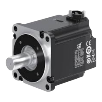
Σ-X-Series AC Servo Drive Rotary Servomotor Product Manual Model: SGMXJ/SGMXA/SGMXP/SGMXG Basic Information on Servomotors Capacity Selection Specifications, Ratings, and External Dimensions of SGMXJ Servomotors Specifications, Ratings, and External Dimensions of SGMXA Servomotors Specifications, Ratings, and External Dimensions of SGMXP Servomotors Specifications, Ratings, and External Dimensions of SGMXG Servomotors Servomotor Installation...
Preface and General Precautions About this Manual ....................10 Outline of Manual ..................... 11 Related Documents ....................12 i.3.1 Related Documents ..................13 Using This Manual....................17 i.4.1 Technical Terms Used in This Manual............17 i.4.2 Trademarks ...................... 17 i.4.3 Visual Aids .......................
i.1 About this Manual About this Manual This manual provides the information needed for the selection, installation, connection, and maintenance of the rotary servomotor of the Σ-X-series AC servo drives. Read and understand this manual to ensure correct usage of the Σ-X-series AC servo drives. Keep this manual in a safe place so that it can be referred to whenever necessary.
i.2 Outline of Manual Outline of Manual The contents of the chapters of this manual are described in the following table. Refer to these chapters as required. Chapter Chapter Title Contents Provides basic information on rotary servomotors, including Basic Information on Servomotors servomotor part names and combinations with SERVOPACKs.
i.3 Related Documents Related Documents The relationships between the documents that are related to the servo drives are shown in the following figure. The numbers in the figure correspond to the numbers in the table on the following pages. Refer to these docu- ments as required.
Related Documents i.3.1 Related Documents (1) Machine Controllers Catalogs You can check for products related to YASKAWA machine controllers. Refer to these documents as required. (2) Servo Drives Catalogs Document Name Document No. Description Provides detailed information on Σ-X-series AC servo...
Page 14
i.3 Related Documents (5) SERVOPACK Product Manuals Document Name Document No. Description Σ-X-Series AC Servo Drive Σ-XS SERVOPACK SIEP C710812 01 with MECHATROLINK-4/III Communica- tions References Product Manual Σ-X-Series AC Servo Drive Σ-XS SERVOPACK SIEP C710812 02 with EtherCAT Communications References Product Manual Σ-X-Series AC Servo Drive Provide detailed information on selecting Σ-X-series Σ-...
Page 15
i.3 Related Documents Continued from previous page. Document Name Document No. Description Σ-X-Series AC Servo Drive Σ-XS/Σ-XW SERVOPACK with MECHATROLINK-4/III Communica- tions References SIEP C710812 19 FT Specification for Gantry Applications Provide information on the gantry application function Product Manual and torque/force assistance in the Σ-X-series Σ-XS/Σ- XW SERVOPACK.
Page 16
i.3 Related Documents (8) MECHATROLINK Communications Command Manuals Document Name Document No. Description Σ-7/Σ-X-Series AC Servo Drive Provides detailed information on the MECHATRO- MECHATROLINK-III Communications SIEP S800001 31 LINK-III communications standard servo profile com- Standard Servo Profile mands that are used for a Σ-7/Σ-X-series servo system. Command Manual Σ-7/Σ-X-Series AC Servo Drive Provides detailed information on the MECHATRO-...
i.4 Using This Manual Using This Manual i.4.1 Technical Terms Used in This Manual The following terms are used in this manual. Term Meaning servomotor Σ-X-series rotary servomotors SERVOPACK Σ-X-series servo amplifier servo drive The combination of a servomotor and SERVOPACK. One of the cables that connect to the SERVOPACK main circuit terminals, including the main circuit cable main circuit power supply cable, control power supply cable, and servomotor main circuit...
i.5 Safety Precautions Safety Precautions i.5.1 Safety Information To prevent personal injury and equipment damage in advance, the following signal words are used to indicate safety precautions in this document. The signal words are used to classify the hazards and the degree of damage or injury that may occur if a product is used incorrectly.
i.5 Safety Precautions CAUTION The SERVOPACK heat sinks, regenerative resistors, external dynamic brake resistors, ser- vomotors, and other components can be very hot while power is ON or soon after the power is turned OFF. Implement safety measures, such as installing covers, so that hands and parts such as cables do not come into contact with hot components.
If storing for longer than six months, reapply anticorrosive coating to the machine machining surfaces, particularly the motor shaft and similar parts. If you will store the product for an extended period of time, contact your Yaskawa representative. (3) Transportation Precautions CAUTION Transport the product in a way that is suitable to the mass of the product.
Page 21
i.5 Safety Precautions NOTICE If disinfectants or insecticides must be used to treat packing materials such as wooden frames, plywood, or pallets, use a method other than fumigation. For example, use heat ster- ilization (core temperature of 56°C or higher for 30 minutes or longer). Treat the packing materials before the product is packaged instead of using a method that treats the entire packaged product.
Page 22
i.5 Safety Precautions NOTICE Do not install or store the product in any of the following locations. • Locations that are subject to direct sunlight • Locations that are subject to surrounding temperatures that exceed product specifications • Locations that are subject to relative humidities that exceed product specifications •...
Page 23
NOTICE Continuous operation in one direction, such as for a fan, may damage the bearings due to electrolytic corrosion. Contact your Yaskawa representative if you will use a servomotor for this type of application. Using a servomotor for oscillating operation may reduce the service life of the bearings.
Page 24
The connectors may break if they are subjected to stress. NOTICE Whenever possible, use the cables specified by Yaskawa. If you use any other cables, con- firm the rated current and application environment of your model and use the wiring materi- als specified by Yaskawa or equivalent materials.
i.5 Safety Precautions NOTICE When connecting a battery, connect the polarity correctly. There is a risk of battery rupture or encoder failure. Always connect the servomotor main circuit cable before you connect the encoder cable. If you connect the encoder cable first, the encoder may be damaged due to the difference in electrical poten- tial from the FG.
i.5 Safety Precautions WARNING Do not enter the machine’s range of motion during operation. There is a risk of injury. Do not touch the moving parts of the servomotor or machine during operation. There is a risk of injury. CAUTION Do not use the holding brake in the servomotor as a brake to stop the servomotor.
i.5 Safety Precautions WARNING Wiring and inspections must be performed only by qualified engineers. There is a risk of electric shock or product failure. Before replacing the servomotor with holding brake, secure the machine side in place. There is a risk of device damage or injury due to falling of a device. CAUTION Wait for at least 20 minutes (or 100 minutes when using DC power supply input) after turning OFF the power and then make sure that the CHARGE indicator is not lit before starting wir-...
Always replace all covers and protective guards before you use the product. • If you need a new copy of this manual because it has been lost or damaged, contact your nearest Yaskawa representative or one of the offices listed on the back of this manual.
Limitations of Liability • Yaskawa shall in no event be responsible for any damage or loss of opportunity to the customer that arises due to failure of the delivered product. • Yaskawa shall not be responsible for any programs (including parameter settings) or the results of program execution of the programs provided by the user or by a third party for use with programmable Yaskawa products.
• The customer must confirm that the Yaskawa product is suitable for the systems, machines, and equipment used by the customer. • Consult with Yaskawa to determine whether use in the following applications is acceptable. If use in the appli- cation is acceptable, use the product with extra allowance in ratings and specifications, and provide safety measures to minimize hazards in the event of failure.
i.7 Compliance with UL Standards, EU Directives, and Other Safety Standards Compliance with UL Standards, EU Directives, and Other Safety Standards Certification marks for the standards for which the product has been certified by certification bodies are shown on nameplate. Products that do not have the marks are not certified for the standards. i.7.1 North American Safety Standards (UL) North American Safety Standards (UL...
Page 32
i.7 Compliance with UL Standards, EU Directives, and Other Safety Standards...
Basic Information on Servomotors This chapter provides basic information on rotary servomotors, including servomotor part names and com- binations with SERVOPACKs. Servomotor Part Names ..................34 1.1.1 SGMXJ servomotors, SGMXA servomotors (Up to 1.0 kW), SGMXP servomotors (Up to 400 W)................34 1.1.2 SGMXG Servomotors (Up to 450 W)..............
1.1 Servomotor Part Names Servomotor Part Names 1.1.1 SGMXJ servomotors, SGMXA servomotors (Up to 1.0 kW), SGMXP servomotors (Up to 400 W) • Standard Servomotors • Servomotors with Brakes 1.1.2 SGMXG Servomotors (Up to 450 W) • Standard Servomotors • Servomotors with Brakes 1.1.3 SGMXA (1.5 kW to 5.0 kW) and SGMXG (600 W or more) Servomotors...
1.1 Servomotor Part Names The position of the nameplate depends on the model and motor output. 1.1.4 SGMXA Servomotors (7.0 kW) 1.1.5 SGMXP Servomotors (750 W, 1.5 kW) • Standard Servomotors • Servomotors with Brakes...
1.2 Interpreting the Nameplate Interpreting the Nameplate The nameplate is printed on the servomotor. The layout of the nameplate depends somewhat on the model of the servomotor. Certification marks for the standards for which the product has been certified by certification bodies are shown on nameplate.
1.3 Outline of Model Designations Outline of Model Designations 1.3.1 Servomotor This section outlines the model numbers of Σ-X-series servomotors. For details, refer to the chapter for your type of servomotor. Standard specification : Only cables that support Σ-LINK II can be used. Term Σ-7 compatible specification : Cables for the Σ-7-series servomotors can be used.
1.4 Combinations of Servomotors and SERVOPACKs Combinations of Servomotors and SERVOPACKs SERVOPACK Model Capacit- Rotary Servomotor Model SGDXS- SGDXW- SGDXT- SGMXJ-A5A 50 W R70A 1R6A , 2R8A 1R6A , 2R8A SGMXJ-01A 100 W R90A 1R6A , 2R8A 1R6A , 2R8A SGMXJ-C2A 150 W 1R6A...
Page 40
1.4 Combinations of Servomotors and SERVOPACKs Continued from previous page. SERVOPACK Model Capacit- Rotary Servomotor Model SGDXS- SGDXW- SGDXT- – SGMXG-03A□A 300 W 3R8A 5R5A , 7R6A SGMXG-05A□A 450 W 3R8A 5R5A , 7R6A – 7R6A – SGMXG-09A□A 850 W 7R6A (120A) 120A...
Capacity Selection This chapter describes calculation methods to use when selecting servomotor capacities. Selecting the Servomotor Capacity..............42 2.1.1 Capacity Selection Example for a Rotary Servomotor (Speed Control)......................43 2.1.2 Capacity Selection Example for a Rotary Servomotor (Position Control)......................45...
2.1 Selecting the Servomotor Capacity Selecting the Servomotor Capacity Contact your Yaskawa representative for information on the servomotor capacity selection software. Refer to the following selection examples to select servomotor capacities with manual calculations.
2.1 Selecting the Servomotor Capacity 2.1.1 Capacity Selection Example for a Rotary Servomotor (Speed Control) Machine Specifications Item Symbol Value Load Speed 15 m/min Linear Motion Section Mass 250 kg Ball Screw Length 1.0 m Ball Screw Diameter 0.02 m Ball Screw Lead 0.01 m Ball Screw Material Density...
Page 44
2.1 Selecting the Servomotor Capacity = (1.58 + 0.31 + 0.40) × 10 = 2.29 × 10 (kg∙m Load Moving Power Load Acceleration Power Servomotor Provisional Selection a. Selection Conditions • T ≤ Motor rated torque • • n ≤ Motor rated speed •...
2.1 Selecting the Servomotor Capacity 2.1.2 Capacity Selection Example for a Rotary Servomotor (Position Control) Machine Specifications Item Symbol Value Load Speed 15 m/min Linear Motion Section Mass 80 kg Ball Screw Length 0.8 m Ball Screw Diameter 0.016 m Ball Screw Lead 0.005 m ρ...
Page 46
2.1 Selecting the Servomotor Capacity Load Moment of Inertia • Linear Motion Section • Ball Screw • Coupling • Load Moment of Inertia at Motor Shaft = 1.25 × 10 (kg∙m Load Moving Power Load Acceleration Power Servomotor Provisional Selection a.
Page 47
2.1 Selecting the Servomotor Capacity • Verification of Effective Torque Value It has been verified that the provisionally selected servomotor is applicable in terms of capacity. Position control is considered next. 10. Positioning Resolution The electrical stopping precision δ = ±0.01 mm, so the positioning resolution Δ = 0.01 mm. The ball screw lead P = 0.005 m, so the number of pulses per motor rotation is calculated using the follow- ing formula.
Specifications, Ratings, and External Dimensions of SGMXJ Servomotors This chapter describes how to interpret the model numbers of SGMXJ servomotors and gives their specifi- cations, ratings, and external dimensions. Model Designations ....................50 Specifications and Ratings..................51 3.2.1 Specification ....................51 3.2.2 Servomotor Ratings ..................
3.2 Specifications and Ratings Specifications and Ratings 3.2.1 Specification Voltage 200 V Model SGMXJ- Time Rating Continuous Thermal Class UL: B, CE: B Insulation Resistance 500 VDC, 10 MΩ min. Withstand Voltage 1,500 VAC for 1 minute Excitation Permanent magnet Mounting Flange-mounted Drive Method...
3.2 Specifications and Ratings The given values are for when the servomotor shaft is mounted horizontally and impact or vibration is applied in the directions shown in the following figures. The strength of the vibration that the servomotor can withstand depends on the application. Always check the vibration acceleration that is applied to the servomotor with the actual equipment.
Page 53
3.2 Specifications and Ratings Continued from previous page. Voltage 200 V Model SGMXJ- Without Rated Holding 37700 47500 50400 24200 26100 23800 15000 Angular Brakes rad/s Accelera- With Hold- tion 31700 42400 46400 19700 23200 22200 13500 ing Brakes Derating Rate for Servo- motor with Oil Seal Heat Sink Size (alumi- 200 ×200 ×6...
Page 54
• The time required to release the brake and the time required to brake depend on which discharge circuit is used. Confirm that the operation delay time is appropriate for the actual equipment. • The 24-VDC power supply is not provided by Yaskawa. The rotor moment of inertia scaling factor is the value for a standard servomotor without a holding brake.
3.2 Specifications and Ratings 3.2.3 Torque-Rotation Speed Characteristics Note: 1. These values (typical values) are for operation in combination with a SERVOPACK when the temperature of the armature winding is 100°C. 2. The characteristics in the intermittent duty zone depend on the power supply voltage. 3.
3.2 Specifications and Ratings Note: The above overload protection characteristics do not mean that you can perform continuous duty operation with an output of 100% or higher. Use the servomotor so that the effective torque remains within the continuous duty zone given in "3.2.3 Torque-Rotation Speed Characteris- tics on page 55".
3.2 Specifications and Ratings Note: Applicable SERVOPACK models: SGDXS-R70A, SGDXS-R90A, SGDXS-1R6A, and SGDXS-2R8A (3) When an External Regenerative Resistor Is Required Install the external regenerative resistor. Refer to the following catalog for details on external regenerative resistors. AC Servo Drives Σ-X Series (Document No.: KAEP C710812 03) 3.2.6 Derating Rates (1) Servomotor Heat Dissipation Conditions...
Page 58
• Use the combination of the SERVOPACK and servomotor so that the derating conditions are satisfied for both the SERVOPACK and servomotor. • The derating rates are applicable only when the average rotation speed is less than or equal to the rated rotation speed. If the average rotation speed exceeds the rated rotation speed, consult with your Yaskawa representative.
3.3 External Dimensions (2) Σ-7 Compatible Specification Model SGMXJ- A5A□A2□A2 25.8 14.7 16.1 01A□A2□A2 25.8 14.7 16.1 C2A□A2□A2 25.8 14.7 16.1 Note: The dimensions for non-connector parts are identical to those for models with standard specifications. (3) Shaft End Specification •...
Page 61
3.3 External Dimensions (5) Connector Mounting Dimensions • Cable Installed on Load Side Standard Specification Σ-7 Compatible Specification • Cable Installed on Non-load Side Standard Specification Σ-7 Compatible Specification...
3.3 External Dimensions 3.3.2 SGMXJ-02 to -06 (1) Standard Specification Flange Dimensions Model SGMXJ- 98.5 68.5 02A□A2□A1 50.5 (139.0) (109.0) 04A□A2□A1 (155.5) (125.5) 06A□A2□A1 (191.0) (161.0) Model Approx. Mass [kg] SGMXJ- 02A□A2□A1 14.5 (1.4) 04A□A2□A1 14.5 (1.7) 06A□A2□A1 14.5 (2.2) For models that have a batteryless absolute encoder, L and LL are 7.5 mm greater and the approximate mass is 0.1 kg greater than the given value.
Page 63
3.3 External Dimensions (2) Σ-7 Compatible Specification Model SGMXJ- 02A□A2□A2 28.7 14.7 17.1 04A□A2□A2 28.7 14.7 17.1 06A□A2□A2 28.7 14.7 17.1 Note: The dimensions for non-connector parts are identical to those for models with standard specifications. (3) Shaft End Specification •...
Page 64
3.3 External Dimensions (5) Connector Mounting Dimensions • Cable Installed on Load Side Standard Specification Σ-7 Compatible Specification • Cable Installed on Non-load Side Standard Specification Σ-7 Compatible Specification...
3.3 External Dimensions 3.3.3 SGMXJ-08 (1) Standard Specification Flange Dimensions Model SGMXJ- 08A□A2□A1 (183.0) (143.0) Model Approx. Mass [kg] SGMXJ- 08A□A2□A1 19.3 (2.8) For models that have a batteryless absolute encoder, L and LL are +6.5 mm greater and the approximate mass is 0.1 kg greater than the given value.
Page 66
3.3 External Dimensions (3) Shaft End Specification • Straight with Key and Tap • With Two Flat Seats (4) Option Specification • With Oil Seal (5) Connector Mounting Dimensions • Cable Installed on Load Side Standard Specification Σ-7 Compatible Specification •...
Specifications, Ratings, and External Dimensions of SGMXA Servomotors This chapter describes how to interpret the model numbers of SGMXA servomotors and gives their speci- fications, ratings, and external dimensions. Model Designations ....................70 Specifications and Ratings..................71 4.2.1 Specification ....................71 4.2.2 Servomotor Ratings ..................
4.2 Specifications and Ratings Specifications and Ratings 4.2.1 Specification Voltage 200 V C2A, 06A, 25A, 40A, Model SGMXA- Time Rating Continuous Thermal Class UL: B, CE: B UL: F, CE: F Insulation Resistance 500 VDC, 10 MΩ min. Withstand Voltage 1500 VAC for 1 minute Excitation Permanent magnet...
4.2 Specifications and Ratings The given values are for when the servomotor shaft is mounted horizontally and impact or vibration is applied in the directions shown in the following figures. The strength of the vibration that the servomotor can withstand depends on the application. Always check the vibration acceleration that is applied to the servomotor with the actual equipment.
Page 73
4.2 Specifications and Ratings Continued from previous page. Voltage 200 V Model SGMXA- Without Rated Holding 72200 93500 103500 45700 58800 60600 30800 32800 Angular Brakes rad/s Accelera- With Hold- tion 53000 75700 88200 31900 46000 50900 25300 27900 ing Brakes Derating Rate for Ser- vomotor with Oil Seal Heat Sink Size (alumi-...
Page 74
• The time required to release the brake and the time required to brake depend on which discharge circuit is used. Confirm that the operation delay time is appropriate for the actual equipment. • The 24-VDC power supply is not provided by Yaskawa. The rotor moment of inertia scaling factor is the value for a standard servomotor without a holding brake.
Page 75
• The time required to release the brake and the time required to brake depend on which discharge circuit is used. Confirm that the operation delay time is appropriate for the actual equipment. • The 24-VDC power supply is not provided by Yaskawa. The rotor moment of inertia scaling factor is the value for a standard servomotor without a holding brake.
Page 76
4.2 Specifications and Ratings To externally connect a dynamic brake resistor, select hardware option specification 0020 for the SERVOPACK. However, you cannot externally connect a dynamic brake resistor if you use the following SERVOPACKs (maximum applicable motor capacity: 400 W). •...
4.2 Specifications and Ratings Note: 1. SGMXA-A5A to -10: These values (typical values) are for operation in combination with a SERVOPACK when the temperature of the armature winding is 100°C. SGMXA-15A to -70: These values (typical values) are for operation in combination with a SERVOPACK when the temperature of the armature winding is 20°C.
4.2 Specifications and Ratings • Reduce the torque limit. • Reduce the deceleration rate. • Reduce the maximum rotation speed. If the above steps are not possible, install an external regenerative resistor. Information An Overvoltage Alarm (A.400) is likely to occur during deceleration if the load moment of inertia exceeds the allowable load moment of inertia.
Page 80
4.2 Specifications and Ratings The actual temperature rise depends on the following conditions. Always check the servomotor temperature with the actual equipment. • How the heat sink (the servomotor mounting section) is attached to the installation surface Important • Status between heat sink and servomotor (sealant, reduction gear, etc.) •...
Page 81
• Use the combination of the SERVOPACK and servomotor so that the derating conditions are satisfied for both the SERVOPACK and servomotor. • The derating rates are applicable only when the average rotation speed is less than or equal to the rated rotation speed. If the average rotation speed exceeds the rated rotation speed, consult with your Yaskawa representative.
4.3 External Dimension (2) Σ-7 Compatible Specification Model SGMXA- A5A□A2□A2 25.8 14.7 16.1 01A□A2□A2 25.8 14.7 16.1 C2A□A2□A2 25.8 14.7 16.1 Note: The dimensions for non-connector parts are identical to those for models with standard specifications. (3) Shaft End Specification •...
Page 84
4.3 External Dimension (5) Connector Mounting Dimensions • Cable Installed on Load Side Standard Specification Σ-7 Compatible Specification • Cable Installed on Non-load Side Standard Specification Σ-7 Compatible Specification...
4.3 External Dimension 4.3.2 SGMXA-02 to -06 (1) Standard Specification Flange Dimensions Model SGMXA- 98.5 68.5 02A□A2□A1 50.5 (139.0) (109.0) 04A□A2□A1 (155.5) (125.5) 06A□A2□A1 (191.0) (161.0) Model Approx. Mass [kg] SGMXA- 02A□A2□A1 14.5 (1.4) 04A□A2□A1 14.5 (1.8) 06A□A2□A1 14.5 (2.2) For models that have a batteryless absolute encoder, L and LL are 7.5 mm greater and the approximate mass is 0.1 kg greater than the given value.
Page 86
4.3 External Dimension (2) Σ-7 Compatible Specification Model SGMXA- 02A□A2□A2 28.7 14.7 17.1 04A□A2□A2 28.7 14.7 17.1 06A□A2□A2 28.7 14.7 17.1 Note: The dimensions for non-connector parts are identical to those for models with standard specifications. (3) Shaft End Specification •...
Page 87
4.3 External Dimension (5) Connector Mounting Dimensions • Cable Installed on Load Side Standard Specification Σ-7 Compatible Specification • Cable Installed on Non-load Side Standard Specification Σ-7 Compatible Specification...
4.3 External Dimension 4.3.3 SGMXA-08 and -10 (1) Standard Specification Flange Dimensions Model SGMXA- 08A□A2□A1 (183.0) (143.0) 10A□A2□A1 (208.0) (168.0) Model Approx. Mass [kg] SGMXA- 08A□A2□A1 19.3 (2.9) 10A□A2□A1 19.3 (3.7) For models that have a batteryless absolute encoder, L and LL are +6.5 mm greater and the approximate mass is 0.1 kg greater than the given value.
Page 89
4.3 External Dimension Note: The dimensions for non-connector parts are identical to those for models with standard specifications. (3) Shaft End Specification • Straight with Key and Tap • With Two Flat Seats (4) Option Specification • With Oil Seal...
4.3 External Dimension (5) Connector Mounting Dimensions • Cable Installed on Load Side Standard Specification Σ-7 Compatible Specification • Cable Installed on Non-load Side Standard Specification Σ-7 Compatible Specification 4.3.4 SGMXA-15 to -25 (1) Servomotors without Holding Brakes (a) Standard Specification...
Page 91
4.3 External Dimension Model SGMXA- (KL1 15A□A21A1 (129) 20A□A21A1 (129) 25A□A21A1 (129) Shaft End Approx. Flange Dimensions Model Dimensions Mass SGMXA- [kg] 15A□A21A1 20A□A21A1 25A□A21A1 For models that have a batteryless absolute encoder, L, LL, LP, and KB2 are 8 mm greater than the given value. Refer to the following section for the values for individual models.
Page 92
FG (frame ground) A battery is required only for an absolute encoder. Receptacle: CMV1-R10P-D Applicable plug (not provided by Yaskawa) Plug: CM10-AP10S-□-D (right-angle type), CM10-SP10S-□-D (straight), CMV1-AP10S-□-D (right-angle type), CMV1-SP10S- □-D (straight), CMV1S-AP10S-□-D (right-angle type), CMV1S-SP10S-□-D (straight) (□ varies depending on the applicable cable size.) Manufacturer: DDK Ltd.
Page 93
4.3 External Dimension Model SGMXA- (KL1 (KL3 15A□A2CA1 (136) (105) 20A□A2CA1 (136) (105) 25A□A2CA1 (136) (105) Shaft End Approx. Flange Dimensions Model Dimensions Mass SGMXA- [kg] 15A□A2CA1 20A□A2CA1 25A□A2CA1 For models that have a batteryless absolute encoder, L, LL, LP, and KB2 are 8 mm greater than the given value. Refer to the following section for the values for individual models.
Page 94
FG (frame ground) A battery is required only for an absolute encoder. Receptacle: CMV1-R10P-D Applicable plug (not provided by Yaskawa) Plug: CM10-AP10S-□-D (right-angle type), CM10-SP10S-□-D (straight), CMV1-AP10S-□-D (right-angle type), CMV1-SP10S- □-D (straight), CMV1S-AP10S-□-D (right-angle type), CMV1S-SP10S-□-D (straight) (□ varies depending on the applicable cable size.) Manufacturer: DDK Ltd.
4.3 External Dimension 4.3.5 SGMXA-30 to -50 (1) Servomotors without Holding Brakes (a) Standard Specification Model SGMXA- (KL1 30A□A21A1 (170) 40A□A21A1 (170) 50A□A21A1 (170) Shaft End Approx. Flange Dimensions Model Dimensions Mass SGMXA- [kg] 30A□A21A1 10.5 40A□A21A1 13.5 50A□A21A1 16.5 For models that have a batteryless absolute encoder, L, LL, LP, and KB2 are +8 mm greater than the given value.
Page 96
4.3 External Dimension (b) Σ-7 Compatible Specification Note: The difference from the model with standard specifications is the shape of the encoder cable connector. The dimensions for non-connector parts are identical to those for models with standard specifications. (c) Shaft End Specification •...
Page 97
FG (frame ground) A battery is required only for an absolute encoder. Receptacle: CMV1-R10P-D Applicable plug (not provided by Yaskawa) Plug: CM10-AP10S-□-D (right-angle type), CM10-SP10S-□-D (straight), CMV1-AP10S-□-D (right-angle type), CMV1-SP10S- □-D (straight), CMV1S-AP10S-□-D (right-angle type), CMV1S-SP10S-□-D (straight) (□ varies depending on the applicable cable size.) Manufacturer: DDK Ltd.
Page 98
4.3 External Dimension Model SGMXA- (KL1 (KL3 30A□A2CA1 (170) (106) 40A□A2CA1 (170) (106) 50A□A2CA1 (170) (106) Shaft End Approx. Flange Dimensions Model Dimensions Mass SGMXA- [kg] 30A□A2CA1 40A□A2CA1 50A□A2CA1 For models that have a batteryless absolute encoder, L, LL, LP, and KB2 are +8 mm greater than the given value. Refer to the follow- ing section for the values for individual models.
Page 99
FG (frame ground) A battery is required only for an absolute encoder. Receptacle: CMV1-R10P-D Applicable plug (not provided by Yaskawa) Plug: CM10-AP10S-□-D (right-angle type), CM10-SP10S-□-D (straight), CMV1-AP10S-□-D (right-angle type), CMV1-SP10S- □-D (straight), CMV1S-AP10S-□-D (right-angle type), CMV1S-SP10S-□-D (straight) (□ varies depending on the applicable cable size.) Manufacturer: DDK Ltd.
4.3 External Dimension 4.3.6 SGMXA-70 (Without Holding Brakes) (1) Standard Specification Note: Mount the servomotor 70 mm or more from walls, machines, and other objects to ensure sufficient cooling air. Model SGMXA- (KL1) 70A□A21A1 (170) Shaft End Approx. Flange Dimensions Model Dimensions Mass...
4.3 External Dimension (3) Cooling Fan Specifications • Single-phase 220 VAC • 50/60 Hz • 17/15 W • 0.11/0.09 A (4) Shaft End Specification • Straight with Key and Tap...
Specifications, Ratings, and External Dimensions of SGMXP Servomotors Describes how to interpret the model numbers of SGMXP servomotors and gives their specifications, rat- ings, and external dimensions. Model Designations ....................106 Specifications and Ratings..................107 5.2.1 Specification ....................107 5.2.2 Servomotor Ratings ..................108 5.2.3 Torque-Rotation Speed Characteristics ............110 5.2.4 Servomotor Overload Protection Characteristics ........110 5.2.5 Allowable Load Moment of Inertia ..............111...
5.2 Specifications and Ratings Specifications and Ratings 5.2.1 Specification Voltage 200 V Model SGMXP- Time Rating Continuous Thermal Class UL: B, CE: B Insulation Resistance 500 VDC, 10 MΩ min. Withstand Voltage 1,500 VAC for 1 minute Excitation Permanent magnet Mounting Flange-mounted Drive Method...
5.2 Specifications and Ratings Refer to the following section for the derating rates. 5.2.6 Derating Rates on page 112 If you use this combination, performance may not be as good, e.g., the control gain may not increase, in comparison with using a Σ- XS SERVOPACK.
Page 109
• The time required to release the brake and the time required to brake depend on which discharge circuit is used. Confirm that the operation delay time is appropriate for the actual equipment. • The 24-VDC power supply is not provided by Yaskawa. The rotor moment of inertia scaling factor is the value for a standard servomotor without a holding brake.
5.2 Specifications and Ratings 5.2.3 Torque-Rotation Speed Characteristics Note: • These values (typical values) are for operation in combination with a SERVOPACK when the temperature of the armature winding is 100° • The characteristics in the intermittent duty zone depend on the power supply voltage. •...
5.2 Specifications and Ratings Note: The above overload protection characteristics do not mean that you can perform continuous duty operation with an output of 100% or higher. Use the servomotor so that the effective torque remains within the continuous duty zone given in "5.2.3 Torque-Rotation Speed Characteris- tics on page 110".
• Use the combination of the SERVOPACK and servomotor so that the derating conditions are satisfied for both the SERVOPACK and servomotor. • The derating rates are applicable only when the average rotation speed is less than or equal to the rated rotation speed. If the average rotation speed exceeds the rated rotation speed, consult with your Yaskawa representative.
5.3 External Dimension External Dimension 5.3.1 SGMXP-01 to -04 (1) Standard Specification Flange Dimensions Model SGMXP- 01A□A2□A1 (113.0) (88.0) 02A□A2□A1 (126.5) (96.5) 04A□A2□A1 (136.5) (106.5) Model Approx. Mass [kg] SGMXP- 01A□A2□A1 14.5 0.4 (0.7) 02A□A2□A1 14.5 1.1 (1.8) 04A□A2□A1 14.5 1.4 (2.1) For models that have a batteryless absolute encoder, L and LL for the SGMXP-01A are 7.5 mm greater, L and LL for the SGMXP- 02A and -04A are 6.5 mm greater, and the approximate mass of the SGMXP-01A, -02A, and -04A is 0.1 kg greater than the given...
5.3 External Dimension (2) Σ-7 Compatible Specification Model SGMXP- 01A□A2□A2 25.8 14.7 16.1 02A□A2□A2 28.7 14.7 17.1 04A□A2□A2 28.7 14.7 17.1 Note: The dimensions for non-connector parts are identical to those for models with standard specifications. (3) Shaft End Specification •...
5.3 External Dimension (5) Connector Mounting Dimensions • Cable Installed on Load Side Standard Specification Σ-7 Compatible Specification • Cable Installed on Non-load Side Standard Specification Σ-7 Compatible Specification 5.3.2 SGMXP-08, -15 (1) Standard Specification Flange Dimensions Model SGMXP- 126.5 86.5 08A□A2□A1 67.6...
Page 116
5.3 External Dimension Model Approx. Mass [kg] SGMXP- 08A□A2□A1 19 (25.5) 4.2 (5.9) 15A□A2□A1 19 (25.5) 6.6 (8.2) For models that have a batteryless absolute encoder, L and LL are +8 mm greater and the approximate mass is 0.1 kg greater than the given value.
5.3 External Dimension (4) Option Specification • With Oil Seal (5) Connector Mounting Dimensions Cable Installed on Load Side Cable Installed on Non-load Side 5.3.3 Dimensions of Servomotors with Batteryless Absolute Encoders Model Approx. Mass SGMXP- [kg] 01AWA2□A□ 90.5 (120.5) 65.5 (95.5) 0.5 (0.8) 02AWA2□A□...
Specifications, Ratings, and External Dimensions of SGMXG Servomotors This chapter describes how to interpret the model numbers of SGMXG servomotors and gives their speci- fications, ratings, and external dimensions. Model Designations ....................120 Specifications and Ratings (1500-min Specification) ........121 6.2.1 Specification ....................121 6.2.2 Servomotor Ratings (SGMXG-03A□A to -20A□A) ........
6.2 Specifications and Ratings (1500-min Specification) Refer to the following section for the derating rates. 6.2.7 Derating Rates on page 129 To increase the instantaneous maximum torque, use the SERVOPACK model in parentheses ( ). Refer to the following section for the instantaneous maximum torque for individual SERVOPACK models. 6.2.2 Servomotor Ratings (SGMXG-03A□A to -20A□A) on page 122 6.2.3 Servomotor Ratings (SGMXG-30A□A to -1EA□A) on page 123 6.2.4 Torque-Rotation Speed Characteristics on page 126...
• The time required to release the brake and the time required to brake depend on which discharge circuit is used. Confirm that the operation delay time is appropriate for the actual equipment. • The 24-VDC power supply is not provided by Yaskawa. The rotor moment of inertia scaling factor is the value for a standard servomotor without a holding brake.
Page 124
6.2 Specifications and Ratings (1500-min Specification) Continued from previous page. Voltage 200 V Model SGMXG- 30A□A 30A□A 44A□A 55A□A 75A□A 1AA□A 1EA□A Without Holding 46.0 67.5 89.0 Brakes Rotor Moment of ×10 Inertia kg∙m With Holding 53.9 75.4 96.9 Brakes Without Holding 75.2 (49.6)
Page 125
• The time required to release the brake and the time required to brake depend on which discharge circuit is used. Confirm that the operation delay time is appropriate for the actual equipment. • The 24-VDC power supply is not provided by Yaskawa. The rotor moment of inertia scaling factor is the value for a standard servomotor without a holding brake.
6.2 Specifications and Ratings (1500-min Specification) Note: • These values (typical values) are for operation in combination with a SERVOPACK when the temperature of the armature winding is 20°C. • The characteristics in the intermittent duty zone depend on the power supply voltage. •...
6.2 Specifications and Ratings (1500-min Specification) The current reference is calculated based on the servomotor's rated current of 24.5 Arms. Note: • The above overload protection characteristics do not mean that you can perform continuous duty operation with an output of 100% or higher.
6.2 Specifications and Ratings (1500-min Specification) capacity of the SERVOPACK and are also affected by the drive conditions of the servomotor. Perform the required steps for each of the following cases. (1) Exceeding the Allowable Load Moment of Inertia Use one of the following measures to adjust the load moment of inertia to within the allowable value. •...
Page 130
• Use the combination of the SERVOPACK and servomotor so that the derating conditions are satisfied for both the SERVOPACK and servomotor. • The derating rates are applicable only when the average rotation speed is less than or equal to the rated rotation speed. If the average rotation speed exceeds the rated rotation speed, consult with your Yaskawa representative.
6.3 Specifications and Ratings (1000-min Specification) Specifications and Ratings (1000-min Specification) 6.3.1 Specification Voltage 200 V Model SGMXG- 03A□B 06A□B 09A□B 12A□B 20A□B 30A□B 40A□B 55A□B Time Rating Continuous Thermal Class UL: F, CE: F Insulation Resistance 500 VDC, 10 MΩ min. Withstand Voltage 1,500 VAC for 1 minute Excitation...
6.3 Specifications and Ratings (1000-min Specification) To increase the instantaneous maximum torque, use the SERVOPACK model in parentheses ( ). Refer to the following section for the instantaneous maximum torque for individual SERVOPACK models. 6.3.2 Servomotor Ratings on page 132 6.3.3 Torque-Rotation Speed Characteristics on page 134 If you use a servomotor together with a Σ-XW SERVOPACK, the control gain may not increase as much as with a Σ-XS SERVO- PACK and other performances may be lower than those achieved with a Σ-XS SERVOPACK.
Page 133
• The time required to release the brake and the time required to brake depend on which discharge circuit is used. Confirm that the operation delay time is appropriate for the actual equipment. • The 24-VDC power supply is not provided by Yaskawa. The rotor moment of inertia scaling factor is the value for a standard servomotor without a holding brake.
6.3 Specifications and Ratings (1000-min Specification) 6.3.3 Torque-Rotation Speed Characteristics Note: • These values (typical values) are for operation in combination with a SERVOPACK when the temperature of the armature winding is 20°C. • The characteristics in the intermittent duty zone depend on the power supply voltage. •...
6.3 Specifications and Ratings (1000-min Specification) Note: • The above overload protection characteristics do not mean that you can perform continuous duty operation with an output of 100% or higher. Use the servomotor so that the effective torque remains within the continuous duty zone given in "6.3.3 Torque-Rotation Speed Character- istics on page 134".
6.3 Specifications and Ratings (1000-min Specification) Information An Overvoltage Alarm (A.400) is likely to occur during deceleration if the load moment of inertia exceeds the allowable load moment of inertia. SERVOPACKs with a built-in regenerative resistor may generate a Regenerative Overload Alarm (A.320).
Page 137
• Use the combination of the SERVOPACK and servomotor so that the derating conditions are satisfied for both the SERVOPACK and servomotor. • The derating rates are applicable only when the average rotation speed is less than or equal to the rated rotation speed. If the average rotation speed exceeds the rated rotation speed, consult with your Yaskawa representative.
6.4 External Dimensions External Dimensions 6.4.1 SGMXG-03A□A, -05A□A, -03A□B (1) Servomotors without Holding Brakes (a) Standard Specification Model SGMXG- (KL1) 03A□A21A1 (70) 05A□A21A1 (70) 03A□B21A1 (70) Shaft End Approx. Flange Dimensions Model Dimensions Mass SGMXG- [kg] 03A□A21A1 05A□A21A1 03A□B21A1 For models that have a batteryless absolute encoder, L, LL, LP, and KB2 are 8 mm greater than the given value. Refer to the following section for the values for individual models.
Page 139
6.4 External Dimensions (b) Σ-7 Compatible Specification Note: The difference from the model with standard specifications is the shape of the encoder cable connector. The dimensions for non-connector parts are identical to those for models with standard specifications. (c) Shaft End Specification •...
Page 140
FG (frame ground) A battery is required only for an absolute encoder. Receptacle: CMV1-R10P Applicable plug (not provided by Yaskawa) Plug: CM10-AP10S-□-D (R1) (right-angle type), CM10-SP10S-□-D (R1) (straight), CMV1-AP10S-□□ (right-angle type), CMV1- SP10S-□□ (straight), CMV1S-AP10S-□□ (right-angle type), CMV1S-SP10S-□□ (straight) (□ varies depending on the applicable cable size.) Manufacturer: DDK Ltd.
Page 141
6.4 External Dimensions Model SGMXG- (KL1) 03A□A2CA1 (70) 05A□A2CA1 (70) 03A□B2CA1 (70) Shaft End Approx. Flange Dimensions Model Dimensions Mass SGMXG- [kg] 03A□A2CA1 05A□A2CA1 03A□B2CA1 For models that have a batteryless absolute encoder, L, LL, LP, and KB2 are 8 mm greater than the given value. Refer to the following section for the values for individual models.
FG (frame ground) A battery is required only for an absolute encoder. Receptacle: CMV1-R10P Applicable plug (not provided by Yaskawa) Plug: CM10-AP10S-□-D (R1) (right-angle type), CM10-SP10S-□-D (R1) (straight), CMV1-AP10S-□□ (right-angle type), CMV1- SP10S-□□ (straight), CMV1S-AP10S-□□ (right-angle type), CMV1S-SP10S-□□ (straight) (□ varies depending on the applicable cable size.) Manufacturer: DDK Ltd.
Page 143
6.4 External Dimensions Model SGMXG- (KL1 09A□A21A1 104 (138) 13A□A21A1 104 (138) 20A□A21A1 104 (138) 06A□B21A1 104 (138) 09A□B21A1 104 (138) 12A□B21A1 104 (138) Shaft End Approx. Flange Dimensions Model Dimensions Mass SGMXG- [kg] 09A□A21A1 13A□A21A1 20A□A21A1 06A□B21A1 09A□B21A1 12A□B21A1 For models that have a batteryless absolute encoder, L, LL, LP, and KB2 are 8 mm greater than the given value.
Page 144
FG (frame ground) A battery is required only for an absolute encoder. Receptacle: CMV1-R10P Applicable plug (not provided by Yaskawa) Plug: CM10-AP10S-□-D (R1) (right-angle type), CM10-SP10S-□-D (R1) (straight), CMV1-AP10S-□□ (right-angle type), CMV1- SP10S-□□ (straight), CMV1S-AP10S-□□ (right-angle type), CMV1S-SP10S-□□ (straight) (□ varies depending on the applicable cable size.) Manufacturer: DDK Ltd.
Page 145
6.4 External Dimensions (2) Servomotors with Holding Brakes (a) Standard Specification Model SGMXG- (KL1 (KL3 09A□A2CA1 (138) (106) 13A□A2CA1 (138) (106) 20A□A2CA1 (138) (106) 06A□B2CA1 (138) (106) 09A□B2CA1 (138) (106) 12A□B2CA1 (138) (106) Shaft End Approx. Flange Dimensions Model Dimensions Mass SGMXG- [kg]...
Page 146
6.4 External Dimensions (b) Σ-7 Compatible Specification Note: The difference from the model with standard specifications is the shape of the encoder cable connector. The dimensions for non-connector parts are identical to those for models with standard specifications. (c) Shaft End Specification •...
Page 147
FG (frame ground) A battery is required only for an absolute encoder. Receptacle: CMV1-R10P Applicable plug (not provided by Yaskawa) Plug: CM10-AP10S-□-D (R1) (right-angle type), CM10-SP10S-□-D (R1) (straight), CMV1-AP10S-□□ (right-angle type), CMV1- SP10S-□□ (straight), CMV1S-AP10S-□□ (right-angle type), CMV1S-SP10S-□□ (straight) (□ varies depending on the applicable cable size.) Manufacturer: DDK Ltd.
6.4 External Dimensions 6.4.3 SGMXG-30A□A to -75A□A, -20A□B to -55A□B (1) Servomotors without Holding Brakes (a) Standard Specification This is 0.04 for the SGMXG-55A□A, -75A□A, -40A□B, and -55A□B. Model SGMXG- (KL1 – 30A□A81A1 134 (190) – 44A□A81A1 134 (190) 55A□A81A1 145 (221) 75A□A81A1 145 (221)
Page 149
6.4 External Dimensions (b) Σ-7 Compatible Specification This is 0.04 for the SGMXG-55A□A, -75A□A, -40A□B, and -55A□B. Note: The difference from the model with standard specifications is the shape of the encoder cable connector. The dimensions for non-connector parts are identical to those for models with standard specifications. (c) Shaft End Specification •...
Page 150
FG (frame ground) A battery is required only for an absolute encoder. Receptacle: CMV1-R10P Applicable plug (not provided by Yaskawa) Plug: CM10-AP10S-□-D (R1) (right-angle type), CM10-SP10S-□-D (R1) (straight), CMV1-AP10S-□□ (right-angle type), CMV1- SP10S-□□ (straight), CMV1S-AP10S-□□ (right-angle type), CMV1S-SP10S-□□ (straight) (□ varies depending on the applicable cable size.) Manufacturer: DDK Ltd.
Page 152
6.4 External Dimensions (b) Σ-7 Compatible Specification This is 0.04 for the SGMXG-55A□A, -75A□A, -40A□B, and -55A□B. Note: The difference from the model with standard specifications is the shape of the encoder cable connector. The dimensions for non-connector parts are identical to those for models with standard specifications. (c) Shaft End Specification •...
Page 153
FG (frame ground) A battery is required only for an absolute encoder. Receptacle: CMV1-R10P Applicable plug (not provided by Yaskawa) Plug: CM10-AP10S-□-D (R1) (right-angle type), CM10-SP10S-□-D (R1) (straight), CMV1-AP10S-□□ (right-angle type), CMV1- SP10S-□□ (straight), CMV1S-AP10S-□□ (right-angle type), CMV1S-SP10S-□□ (straight) (□ varies depending on the applicable cable size.) Manufacturer: DDK Ltd.
6.4 External Dimensions 6.4.4 SGMXG-1A, -1E (1) Servomotors without Holding Brakes (a) Standard Specification Model SGMXG- (KL1 1AA□A81A1 (245) 1EA□A81A1 (245) Flange Dimensions Shaft End Dimensions Appro- Model Mass SGMXG- [kg] M16 × 1AA□A81A1 13.5 M20 × 1EA□A81A1 13.5 For models that have a batteryless absolute encoder, L, LL, LP, and KB2 are 8 mm greater than the given value. Refer to the following section for the values for individual models.
Page 155
FG (frame ground) A battery is required only for an absolute encoder. Receptacle: CMV1-R10P Applicable plug (not provided by Yaskawa) Plug: CM10-AP10S-□-D (R1) (right-angle type), CM10-SP10S-□-D (R1) (straight), CMV1-AP10S-□□ (right-angle type), CMV1- SP10S-□□ (straight), CMV1S-AP10S-□□ (right-angle type), CMV1S-SP10S-□□ (straight) (□ varies depending on the applicable cable size.) Manufacturer: DDK Ltd.
Page 156
6.4 External Dimensions (2) Servomotors with Holding Brakes (a) Standard Specification Model SGMXG- (KL1 (KL3 1AA□A8CA1 (245) (151) 1EA□A8CA1 (245) (151) Flange Dimensions Shaft End Dimensions Appro- Model Mass SGMXG- [kg] M16 × 1AA□A8CA1 13.5 M20 × 1EA□A8CA1 13.5 For models that have a batteryless absolute encoder, L, LL, LP, and KB2 are 8 mm greater than the given value. Refer to the following section for the values for individual models.
Page 157
6.4 External Dimensions (c) Shaft End Specification • Straight with Key and Tap Model SGMXG- 1AA□A6C□□ M16 × 32 1EA□A6C□□ M20 × 40...
Page 158
FG (frame ground) A battery is required only for an absolute encoder. Receptacle: CMV1-R10P Applicable plug (not provided by Yaskawa) Plug: CM10-AP10S-□-D (R1) (right-angle type), CM10-SP10S-□-D (R1) (straight), CMV1-AP10S-□□ (right-angle type), CMV1- SP10S-□□ (straight), CMV1S-AP10S-□□ (right-angle type), CMV1S-SP10S-□□ (straight) (□ varies depending on the applicable cable size.) Manufacturer: DDK Ltd.
Servomotor Installation This chapter describes the installation conditions, procedures, and precautions for servomotors. Installation Conditions..................162 7.1.1 Installation Precautions................162 7.1.2 Installation Environment ................162 7.1.3 Installation Orientation ................. 162 7.1.4 Using Servomotors with Oil Seals............... 162 7.1.5 Using Servomotors with Holding Brakes ........... 163 Coupling to the Machine..................164 7.2.1 Using a Coupling ...................
7.1 Installation Conditions Installation Conditions The service life of a servomotor will be shortened or unexpected problems will occur if the servomotor is installed incorrectly or in an inappropriate environment or location. Always observe the following installation instructions. 7.1.1 Installation Precautions Refer to the following section for the installation precautions.
For this reason, periodically perform continuous operation, such as by running the motor shaft at the rated speed. Contact your Yaskawa representative if you will use a servomotor in an application that is not suited to continuous operation.
7.2 Coupling to the Machine Coupling to the Machine You can couple the servomotor to the machine with either a coupling or a belt. Use the following procedures. 7.2.1 Using a Coupling • Use a flexible coupling that is designed for servomotors. We recommend that you use a double-spring coupling, which pro- vides some tolerance in eccentricity and deflection.
7.2 Coupling to the Machine 7.2.2 Using a Belt Select a coupling belt that is suitable for the allowable radial load of the servomotor and the servomotor output. When the servomotor accelerates or decelerates, the counterforce from the acceleration/deceleration torque adds tension to the initial belt tension.
If contact with oil or water is unavoidable, use oil-resistant cables. Oil-resistant cables are not provided by Yaskawa. • If you install the servomotor with the end of the shaft facing up, do not use the servomotor where oil or water from the machine, a gear box, or other source would come into contact with the servomotor.
7.4 Servomotor Temperature Increase Servomotor Temperature Increase This section describes measures to suppress temperature increases in the servomotor. • When you install the servomotor, observe the cooling conditions (heat sink sizes) that are given in the specifi- cations for each type of servomotor. The servomotor generates heat when it operates.
Connections between Servomotors and SERVOPACKs This chapter describes the cables that are used to connect one servomotor to the SERVOPACK and pro- vides related precautions. Cables for the SGMXJ Servomotors..............170 8.1.1 System Configurations ................. 170 8.1.2 Servomotor Main Circuit Cables..............172 8.1.3 Encoder Cables (When Not Relaying the Encoder Cable) ......
8.1 Cables for the SGMXJ Servomotors Cables for the SGMXJ Servomotors Information Refer to the following manual for details on connecting multiple devices to the SERVOPACK. Σ-X-Series Peripheral Device Selection Manual (Manual No.: SIEP C710812 12) 8.1.1 System Configurations (1) Servomotors with Standard Specifications The cables shown below are required to connect a servomotor to a SERVOPACK.
Page 171
8.1 Cables for the SGMXJ Servomotors (2) Servomotors with Σ-7 Compatible Specifications The cables shown below are required to connect a servomotor to a SERVOPACK. Note: 1. The encoder cable to use depends on whether the encoder cable will be relayed. Be sure to use the relay encoder cable with connectors at both ends in combination with the relay encoder cable as shown in the illustration at the upper right.
8.1 Cables for the SGMXJ Servomotors 8.1.2 Servomotor Main Circuit Cables This section provides information on selecting a servomotor main circuit cable. Refer to the following manual for detailed information on cables and for the wiring materials to make your own cables. Σ-X-Series Peripheral Device Selection Manual (Manual No.: SIEP C710812 12) (1) Servomotors with Standard Specifications (a) SGMXJ-A5 to -06 (50 to 600 W)
Page 173
8.1 Cables for the SGMXJ Servomotors The recommended bending radius (R) is 90 mm or larger. (b) SGMXJ-08 (750 W) Order Number Length Name Appearance Standard Cable Flexible Cable *1 *2 JWSP-XM08NS1-03 JWSP-XM08NF1-03 JWSP-XM08NS1-05 JWSP-XM08NF1-05 10 m JWSP-XM08NS1-10 JWSP-XM08NF1-10 For servomotors without 15 m JWSP-XM08NS1-15 JWSP-XM08NF1-15...
Page 174
8.1 Cables for the SGMXJ Servomotors (2) Servomotors with Σ-7 Compatible Specifications (a) SGMXJ-A5 to -C2 (50 to 150 W) Order Number Length Name Appearance Standard Cable Flexible Cable *1 *2 JZSP-C7M10F-03-E JZSP-C7M12F-03-E JZSP-C7M10F-05-E JZSP-C7M12F-05-E 10 m JZSP-C7M10F-10-E JZSP-C7M12F-10-E For servomotors without 15 m JZSP-C7M10F-15-E JZSP-C7M12F-15-E...
Page 175
8.1 Cables for the SGMXJ Servomotors (b) SGMXJ-02 to -06 (200 to 600 W) Order Number Length Name Appearance Standard Cable Flexible Cable *1 *2 JZSP-C7M20F-03-E JZSP-C7M22F-03-E JZSP-C7M20F-05-E JZSP-C7M22F-05-E 10 m JZSP-C7M20F-10-E JZSP-C7M22F-10-E For servomotors without 15 m JZSP-C7M20F-15-E JZSP-C7M22F-15-E holding brakes 20 m JZSP-C7M20F-20-E...
Page 176
8.1 Cables for the SGMXJ Servomotors (c) SGMXJ-08 (750 W) Order Number Length Name Appearance Standard Cable Flexible Cable *1 *2 JZSP-C7M30F-03-E JZSP-C7M32F-03-E JZSP-C7M30F-05-E JZSP-C7M32F-05-E 10 m JZSP-C7M30F-10-E JZSP-C7M32F-10-E For servomotors without 15 m JZSP-C7M30F-15-E JZSP-C7M32F-15-E holding brakes 20 m JZSP-C7M30F-20-E JZSP-C7M32F-20-E Cable installed toward load...
8.1 Cables for the SGMXJ Servomotors 8.1.3 Encoder Cables (When Not Relaying the Encoder Cable) (1) Servomotors with Standard Specifications Order Number Length Name Appearance Standard Cable Flexible Cable *1 *2 JWSP-XP2IS1-03 JWSP-XP2IF1-03 JWSP-XP2IS1-05 JWSP-XP2IF1-05 10 m JWSP-XP2IS1-10 JWSP-XP2IF1-10 For batteryless absolute 15 m JWSP-XP2IS1-15 JWSP-XP2IF1-15...
Page 179
8.1 Cables for the SGMXJ Servomotors (2) Servomotors with Σ-7 Compatible Specifications (20 m or Less) Order Number Length Name Appearance Standard Cable Flexible Cable *1 *2 JZSP-C7PI0D-03-E JZSP-C7PI2D-03-E JZSP-C7PI0D-05-E JZSP-C7PI2D-05-E For batteryless absolute encoder 10 m JZSP-C7PI0D-10-E JZSP-C7PI2D-10-E Cable installed toward load 15 m JZSP-C7PI0D-15-E JZSP-C7PI2D-15-E...
8.1 Cables for the SGMXJ Servomotors 8.1.4 Encoder Cables (When Relaying the Encoder Cable) (1) Servomotors with Standard Specifications When you will relay the encoder cable, use the following configuration. Cables: 2 cables, cable relay point: 1 location, combined cable length: 50 m Order Number Length Name...
Page 181
8.1 Cables for the SGMXJ Servomotors Continued from previous page. Order Number Length Name Appearance Standard Cable Flexible Cable *1 *2 0.3 m JWSP-XP3IS2-00P3 JWSP-XP3IF2-00P3 JWSP-XP3IS2-01 JWSP-XP3IF2-01 JWSP-XP3IS2-03 JWSP-XP3IF2-03 JWSP-XP3IS2-05 JWSP-XP3IF2-05 10 m JWSP-XP3IS2-10 JWSP-XP3IF2-10 Encoder cable 15 m JWSP-XP3IS2-15 JWSP-XP3IF2-15 Cable installed away from load...
8.2 Cables for the SGMXA Servomotors Cables for the SGMXA Servomotors Information Refer to the following manual for details on connecting multiple devices to the SERVOPACK. Σ-X-Series Peripheral Device Selection Manual (Manual No.: SIEP C710812 12) 8.2.1 System Configurations (1) Servomotors with Standard Specifications The cables shown below are required to connect a servomotor to a SERVOPACK.
Page 183
8.2 Cables for the SGMXA Servomotors Note: 1. The encoder cable to use depends on whether the encoder cable will be relayed. 2. When you will relay the encoder cable, use the following configuration. Cables: 2 cables, cable relay point: 1 location, combined cable length: 50 m 3.
Page 184
8.2 Cables for the SGMXA Servomotors (2) Servomotors with Σ-7 Compatible Specifications The cables shown below are required to connect a servomotor to a SERVOPACK. • SGMXA-A5 to -10 • SGMXA-15 to -70 Note: 1. The encoder cable to use depends on whether the encoder cable will be relayed. 2.
Page 185
8.2 Cables for the SGMXA Servomotors There are different order numbers for the servomotor main circuit cables and encoder cables depending on the cable installa- tion direction. Confirm the order numbers before you order. • SGMXA-A5 to -10 Important • SGMXA-15 to -70...
8.2 Cables for the SGMXA Servomotors 8.2.2 Servomotor Main Circuit Cables This section provides information on selecting a servomotor main circuit cable. Refer to the following manual for detailed information on cables and for the wiring materials to make your own cables. Σ-X-Series Peripheral Device Selection Manual (Manual No.: SIEP C710812 12) (1) Servomotors with Standard Specifications (a) SGMXA-A5 to -06 (50 to 600 W)
Page 187
8.2 Cables for the SGMXA Servomotors The recommended bending radius (R) is 90 mm or larger. (b) SGMXA-08, -10 (750 W, 1.0 kW) Order Number Length Name Appearance Standard Cable Flexible Cable *1 *2 JWSP-XM08NS1-03 JWSP-XM08NF1-03 JWSP-XM08NS1-05 JWSP-XM08NF1-05 10 m JWSP-XM08NS1-10 JWSP-XM08NF1-10 For servomotors without...
Page 188
Use flexible cables for moving parts of machines, such as robots. The recommended bending radius (R) is 90 mm or larger. The lead installation direction is the non-load side. Contact your Yaskawa representative if you require the leads to be installed in another direction.
Page 189
Use flexible cables for moving parts of machines, such as robots. The recommended bending radius (R) is 90 mm or larger. The lead installation direction is the non-load side. Contact your Yaskawa representative if you require the leads to be installed in another direction.
Page 190
Use flexible cables for moving parts of machines, such as robots. The recommended bending radius (R) is 90 mm or larger. The lead installation direction is the non-load side. Contact your Yaskawa representative if you require the leads to be installed in another direction.
Page 191
Use flexible cables for moving parts of machines, such as robots. The recommended bending radius (R) is 90 mm or larger. The lead installation direction is the non-load side. Contact your Yaskawa representative if you require the leads to be installed in another direction.
Page 192
JWSP-XM70NFL-20 These standard cables are flexible cables. The recommended bending radius (R) is 90 mm or larger. The lead installation direction is the non-load side. Contact your Yaskawa representative if you require the leads to be installed in another direction.
Page 193
8.2 Cables for the SGMXA Servomotors (2) Servomotors with Σ-7 Compatible Specifications (a) SGMXA-A5 to -C2 (50 W to 150 W) Order Number Length Name Appearance Standard Cable Flexible Cable *1 *2 JZSP-C7M10F-03-E JZSP-C7M12F-03-E JZSP-C7M10F-05-E JZSP-C7M12F-05-E 10 m JZSP-C7M10F-10-E JZSP-C7M12F-10-E For servomotors without 15 m JZSP-C7M10F-15-E...
Page 194
8.2 Cables for the SGMXA Servomotors (b) SGMXA-02 to -06 (200 W to 600 W) Order Number Length Name Appearance Standard Cable Flexible Cable *1 *2 JZSP-C7M20F-03-E JZSP-C7M22F-03-E JZSP-C7M20F-05-E JZSP-C7M22F-05-E 10 m JZSP-C7M20F-10-E JZSP-C7M22F-10-E For servomotors without 15 m JZSP-C7M20F-15-E JZSP-C7M22F-15-E holding brakes 20 m...
Page 195
8.2 Cables for the SGMXA Servomotors (c) SGMXA-08, -10 (750 W, 1.0 kW) Order Number Length Name Appearance Standard Cable Flexible Cable *1 *2 JZSP-C7M30F-03-E JZSP-C7M32F-03-E JZSP-C7M30F-05-E JZSP-C7M32F-05-E 10 m JZSP-C7M30F-10-E JZSP-C7M32F-10-E For servomotors without 15 m JZSP-C7M30F-15-E JZSP-C7M32F-15-E holding brakes 20 m JZSP-C7M30F-20-E JZSP-C7M32F-20-E...
8.2 Cables for the SGMXA Servomotors 8.2.3 Encoder Cables (When Not Relaying the Encoder Cable) (1) Servomotors with Standard Specifications Order Number Length Name Appearance Standard Cable Flexible Cable *1 *2 JWSP-XP2IS1-03 JWSP-XP2IF1-03 JWSP-XP2IS1-05 JWSP-XP2IF1-05 For batteryless absolute 10 m JWSP-XP2IS1-10 JWSP-XP2IF1-10 encoder...
Page 197
8.2 Cables for the SGMXA Servomotors Note: Do not use these cables as relay cables. (2) Servomotors with Σ-7 Compatible Specifications (20 m or Less) (a) SGMXA-A5 to -10 (50 W to 1.0 kW) Order Number Length Name Appearance Standard Cable Flexible Cable *1 *2 JZSP-C7PI0D-03-E...
Page 198
The recommended bending radius (R) is 46 mm or larger. If a battery is connected to the host controller, the battery unit is not required. The lead installation direction is the non-load side. Contact your Yaskawa representative if you require the leads to be installed in another direction.
8.2 Cables for the SGMXA Servomotors 8.2.4 Encoder Cables (When Relaying the Encoder Cable) (1) Servomotors with Standard Specifications When you will relay the encoder cable, use the following configuration. Cables: 2 cables, cable relay point: 1 location, combined cable length: 50 m Order Number Length Name...
Page 200
8.2 Cables for the SGMXA Servomotors Continued from previous page. Order Number Length Appearance Name Standard Cable Flexible Cable *1 *2 0.3 m JWSP-XP3IS2-00P3 JWSP-XP3IF2-00P3 JWSP-XP3IS2-01 JWSP-XP3IF2-01 JWSP-XP3IS2-03 JWSP-XP3IF2-03 JWSP-XP3IS2-05 JWSP-XP3IF2-05 Encoder Cables 10 m JWSP-XP3IS2-10 JWSP-XP3IF2-10 SGMXA-A5 to -10: Cable installed away from load 15 m JWSP-XP3IS2-15...
Page 201
(Required only when an absolute encoder is used. The lead installation direction of the right-angle plug connector is the non-load side. Contact your Yaskawa representative if you require the leads to be installed in another direction. An encoder cable with a right-angle plug cannot be used for the SGMXA-70 (7.0 kW). Use an encoder cable with a straight plug.
8.3 Cables for the SGMXP Servomotors Cables for the SGMXP Servomotors Information Refer to the following manual when making connections between multiple devices and the SERVOPACK. Σ-X-Series Peripheral Device Selection Manual (Manual No.: SIEP C710812 12) 8.3.1 System Configurations (1) Servomotors with Standard Specifications The cables shown below are required to connect a servomotor to a SERVOPACK.
Page 203
8.3 Cables for the SGMXP Servomotors Note: 1. The encoder cable to use depends on whether the encoder cable will be relayed. 2. When you will relay the encoder cable for the SGMXP-01 to -04 servomotor, use the following configuration. Cables: 2 cables, cable relay point: 1 location, combined cable length: 50 m 3.
8.3 Cables for the SGMXP Servomotors Note: 1. The encoder cable to use depends on whether the encoder cable will be relayed. 2. If you use a servomotor main circuit cable that exceeds 20 m, the intermittent duty zone in the torque-rotation speed characteristics will become smaller because the voltage drop increases.
Page 205
8.3 Cables for the SGMXP Servomotors (1) Servomotors with Standard Specifications (a) SGMXP-01 to -04 (100 to 400 W) Order Number Length Name Appearance Standard Cable Flexible Cable *1 *2 JWSP-XMA5NS1-03 JWSP-XMA5NF1-03 JWSP-XMA5NS1-05 JWSP-XMA5NF1-05 10 m JWSP-XMA5NS1-10 JWSP-XMA5NF1-10 For servomotors without 15 m JWSP-XMA5NS1-15 JWSP-XMA5NF1-15...
Page 206
8.3 Cables for the SGMXP Servomotors (b) SGMXP-08 (750 W) Order Number Length Name Appearance Standard Cable Flexible Cable *1 *2 JZSP-CMM00-03-E JZSP-CMM01-03-E JZSP-CMM00-05-E JZSP-CMM01-05-E 10 m JZSP-CMM00-10-E JZSP-CMM01-10-E 15 m JZSP-CMM00-15-E JZSP-CMM01-15-E For servomotors without holding brakes 20 m JZSP-CMM00-20-E JZSP-CMM01-20-E 30 m...
Page 207
8.3 Cables for the SGMXP Servomotors (2) Servomotors with Σ-7 Compatible Specifications (a) SGMXP-01 (100 W) Order Number Length Name Appearance Standard Cable Flexible Cable *1 *2 JZSP-C7M10F-03-E JZSP-C7M12F-03-E JZSP-C7M10F-05-E JZSP-C7M12F-05-E 10 m JZSP-C7M10F-10-E JZSP-C7M12F-10-E For servomotors without 15 m JZSP-C7M10F-15-E JZSP-C7M12F-15-E holding brakes...
Page 208
8.3 Cables for the SGMXP Servomotors (b) SGMXP-02 to -04 (200 to 400 W) Order Number Length Name Appearance Standard Cable Flexible Cable *1 *2 JZSP-C7M20F-03-E JZSP-C7M22F-03-E JZSP-C7M20F-05-E JZSP-C7M22F-05-E 10 m JZSP-C7M20F-10-E JZSP-C7M22F-10-E For servomotors without 15 m JZSP-C7M20F-15-E JZSP-C7M22F-15-E holding brakes 20 m JZSP-C7M20F-20-E...
8.3 Cables for the SGMXP Servomotors 8.3.3 Encoder Cables (When Not Relaying the Encoder Cable) (1) Servomotors with Standard Specifications Order Number Length Name Appearance Standard Cable Flexible Cable *1 *2 JWSP-XP2IS1-03 JWSP-XP2IF1-03 JWSP-XP2IS1-05 JWSP-XP2IF1-05 10 m JWSP-XP2IS1-10 JWSP-XP2IF1-10 For batteryless absolute 15 m JWSP-XP2IS1-15 JWSP-XP2IF1-15...
Page 210
8.3 Cables for the SGMXP Servomotors (2) Servomotors with Σ-7 Compatible Specifications (20 m or Less) (a) SGMXP-01 to -04 (100 to 400 W) Order Number Length Name Appearance Standard Cable Flexible Cable *1 *2 JZSP-C7PI0D-03-E JZSP-C7PI2D-03-E JZSP-C7PI0D-05-E JZSP-C7PI2D-05-E For batteryless absolute encoder 10 m JZSP-C7PI0D-10-E...
8.3 Cables for the SGMXP Servomotors Use flexible cables for moving parts of machines, such as robots. The recommended bending radius (R) is 46 mm or larger. If a battery is connected to the host controller, the battery unit is not required. 8.3.4 Encoder Cables (When Relaying the Encoder Cable) (1) Servomotors with Standard Specifications...
Page 212
8.3 Cables for the SGMXP Servomotors Continued from previous page. Order Number Length Appearance Name Standard Cable Flexible Cable *1 *2 0.3 m JWSP-XP3IS2-00P3 JWSP-XP3IF2-00P3 JWSP-XP3IS2-01 JWSP-XP3IF2-01 JWSP-XP3IS2-03 JWSP-XP3IF2-03 JWSP-XP3IS2-05 JWSP-XP3IF2-05 10 m JWSP-XP3IS2-10 JWSP-XP3IF2-10 Encoder Cables 15 m JWSP-XP3IS2-15 JWSP-XP3IF2-15 Cable installed away from load...
1. Cables with connectors on both ends that are compliant with an IP67 protective structure and European Safety Standards are not available from Yaskawa for the SGMXG servomotors. You must make such a cable yourself. Use the connectors specified by Yaskawa for these servomotors.
Page 214
1. Cables with connectors on both ends that are compliant with an IP67 protective structure and European Safety Standards are not available from Yaskawa for the SGMXG servomotors. You must make such a cable yourself. Use the connectors specified by Yaskawa for these servomotors.
8.4 Cables for the SGMXG Servomotors 8.4.2 Servomotor Main Circuit Cables The servomotor main circuit cable is the same for both standard specification servomotors and Σ-7 compatible specification servomotors. Information For Σ-7 compatible specification servomotors, you can also use the same cables as for Σ-7 series rotary servomotors. Refer to the following manual for details on the cables for Σ-7 series rotary servomotors.
Page 216
Use flexible cables for moving parts of machines, such as robots. The recommended bending radius (R) is 90 mm or larger. The lead installation direction is the non-load side. Contact your Yaskawa representative if you require the leads to be installed in another direction.
Page 217
Use flexible cables for moving parts of machines, such as robots. The recommended bending radius (R) is 90 mm or larger. The lead installation direction is the non-load side. Contact your Yaskawa representative if you require the leads to be installed in another direction.
Page 218
Use flexible cables for moving parts of machines, such as robots. The recommended bending radius (R) is 90 mm or larger. The lead installation direction is the non-load side. Contact your Yaskawa representative if you require the leads to be installed in another direction.
Page 219
Use flexible cables for moving parts of machines, such as robots. The recommended bending radius (R) is 90 mm or larger. The lead installation direction is the non-load side. Contact your Yaskawa representative if you require the leads to be installed in another direction.
Page 220
Use flexible cables for moving parts of machines, such as robots. The recommended bending radius (R) is 90 mm or larger. The lead installation direction is the non-load side. Contact your Yaskawa representative if you require the leads to be installed in another direction.
Page 221
Use flexible cables for moving parts of machines, such as robots. The recommended bending radius (R) is 90 mm or larger. The lead installation direction is the non-load side. Contact your Yaskawa representative if you require the leads to be installed in another direction.
Page 222
JWSP-XM1ABFL-20 These standard cables are flexible cables. The recommended bending radius (R) is 90 mm or larger. The lead installation direction is the non-load side. Contact your Yaskawa representative if you require the leads to be installed in another direction.
8.4 Cables for the SGMXG Servomotors 8.4.3 Encoder Cables (When Not Relaying the Encoder Cable) (1) Servomotors with Standard Specifications Order Number Length Name Appearance Standard Cable Flexible Cable *1 *2 JWSP-XP2IS1-03 JWSP-XP2IF1-03 JWSP-XP2IS1-05 JWSP-XP2IF1-05 10 m JWSP-XP2IS1-10 JWSP-XP2IF1-10 For batteryless absolute 15 m JWSP-XP2IS1-15 JWSP-XP2IF1-15...
Page 225
The recommended bending radius (R) is 46 mm or larger. If a battery is connected to the host controller, the battery unit is not required. The lead installation direction is the non-load side. Contact your Yaskawa representative if you require the leads to be installed in another direction.
8.4 Cables for the SGMXG Servomotors 8.4.4 Encoder Cables (When Relaying the Encoder Cable) (1) Servomotors with Standard Specifications When you will relay the encoder cable, use the following configuration. Cables: 2 cables, cable relay point: 1 location, combined cable length: 50 m Order Number Length Name...
Page 227
(Required only when an absolute encoder is used. The lead installation direction of the right-angle plug connector is the non-load side. Contact your Yaskawa representative if you require the leads to be installed in another direction. This cable is not required if you use a servomotor with a batteryless absolute encoder, and you connect a battery to the host controller.
8.5 Wiring Servomotors and SERVOPACKs Wiring Servomotors and SERVOPACKs 8.5.1 Wiring Precautions CAUTION Do not connect the servomotor directly to an industrial power supply. Doing so will destroy the servomotor. You cannot operate a servomotor without a SERVOPACK that is designed for it.
8.5 Wiring Servomotors and SERVOPACKs (4) Precautions for Flexible Cables • The flexible cables have a service life of 10,000,000 operations minimum when used at the recommended bending radius of 90 mm or larger under the following test conditions. The service life of a flexible cable is reference data under special test conditions.
Page 230
8.5 Wiring Servomotors and SERVOPACKs Attach the servomotor main circuit cable and tighten the screws. Pay attention to the orientation of the cable (i.e., load or non-load side) when you attach it. Information There are two servomotor main circuit cables for the SGMXG-09A□A to -1EA□A and -06A□B to -55A□B servomotors with holding brakes (the main power supply cable and the holding brake cable).
Page 231
8.5 Wiring Servomotors and SERVOPACKs (b) Servomotors with Σ-7 Compatible Specifications Attach the relay encoder cable and tighten the screws. Pay attention to the orientation of the cable (SGMXJ servomotors, SGMXA-A5 to -10 servomotors, and SGMXP servo- motors: load or non-load side) when you attach it. The tightening torque for SGMXJ servomotors, SGMXA servomotors (up to 1.0 kW), SGMXP servo- motors (up to 400 W) is 0.15 N∙m.
Maintenance and Inspection This chapter describes the maintenance, inspection, and disposal of a servomotor. Periodic Inspections....................234 Service Lives of Parts ...................235 Disposing of Servomotors ...................236...
There is a risk of electric shock. Contact your Yaskawa representative for help with failures, repairs, or part replacement. The following table gives the periodic inspection items for a servomotor. The inspection periods given in the table are guidelines. Determine the optimum inspection periods based on the application conditions and environment.
Service Lives of Parts The following table gives the standard service lives of the parts of the servomotor. Contact your Yaskawa repre- sentative using the following table as a guide. After an examination of the part in question, we will determine whether the part should be replaced.
9.3 Disposing of Servomotors Disposing of Servomotors When disposing of a servomotor, treat it as ordinary industrial waste. However, local ordinances and national laws must be observed. Implement all labeling and warnings as a final product as required.
Appendices The appendices provide reference information on selecting servomotor capacity. 10.1 Reference Information for Servomotor Capacity Selection ......238 10.1.1 Formulas Required to Select the Servomotor Capacity ......238 10.1.2 GD for Simple Diagrams................239 10.1.3 Conversions between Engineering Units and SI Units ......240 10.1.4 Application Examples by Type of Application ...........
10.1 Reference Information for Servomotor Capacity Selection 10.1 Reference Information for Servomotor Capacity Selection 10.1.1 Formulas Required to Select the Servomotor Capacity Linear Motion Type of Motion Rotary Motion Horizontal Axis Vertical Axis N : Load shaft speed (min V : Load speed (m/min) T : Load torque calculated at load shaft (N∙m) Machine Configuration μ: Friction coefficient...
10.1 Reference Information for Servomotor Capacity Selection Continued from previous page. Linear Motion Type of Motion Rotary Motion Horizontal Axis Vertical Axis Minimum Braking Time (s) Load Moving Power (W) Load Acceleration Power (W) Required Starting Torque (N∙m) Required Braking Torque (N∙m) Effective Torque Value (N∙m) 10.1.2 GD for Simple Diagrams...
10.1 Reference Information for Servomotor Capacity Selection 10.1.3 Conversions between Engineering Units and SI Units The following table provides the conversion rates between engineering units and SI units for typical physical quantities required for capacity selection. Quantity Engineering Unit SI Unit Conversion Factor Force or load 1 kgf = 9.80665 N...
10.1 Reference Information for Servomotor Capacity Selection 10.1.4 Application Examples by Type of Application Horizontal Rotary Ball Type Rotating Body Vertical Ball Screw Screw Machine Configuration Load Rotation Speed N (min Speed Calculated at Motor Shaft N (min R × N R ×...
Page 242
10.1 Reference Information for Servomotor Capacity Selection Type Roll Feeder Rack and Pinion Machine Configuration Load Rotation Speed N (min R × N R × N Speed Calculated at Motor Shaft N (min Calculated at Load Shaft Linear Motion GD (kg∙m Calculated at Motor Shaft...
Page 243
10.1 Reference Information for Servomotor Capacity Selection Type Chains and Timing Belts Dollies Machine Configuration Load Rotation Speed N (min Speed Calculated at Motor Shaft N (min R × N R × N Calculated at Load Shaft Linear Motion GD (kg∙m Calculated at Motor Shaft...
Revision History The date of publication, revision code, revision number, and web revision number are given at the bottom right of the back cover. Refer to the following example. Date of Rev. Web Rev. Rev. No. Section Revised Contents Publication Code September 2023 1.4, Chapter 6,...
Need help?
Do you have a question about the E-X Series and is the answer not in the manual?
Questions and answers