YASKAWA E-V Series User Manual
Ac servo drives
Hide thumbs
Also See for E-V Series:
- User manual (435 pages) ,
- User manual (123 pages) ,
- User manual (223 pages)
Table of Contents
Advertisement
Quick Links
AC Servo Drives
V
-
Series
USER'S MANUAL
Safety Module
Model: SGDV-OSA01A
MANUAL NO. SIEP C720829 06B
Checking Products
Specifications
SERVOPACK Installation
Wiring and Connection
Precautions and Basic Settings
Required before Starting Operation
Safety Functions
Setting Parameters
Utility Functions
Monitor Mode
Active Mode Function
Troubleshooting
Appendix
1
2
3
4
5
6
7
8
9
10
11
12
Advertisement
Table of Contents
Troubleshooting

Related Manuals for YASKAWA E-V Series


Summary of Contents for YASKAWA E-V Series
- Page 1 AC Servo Drives Series USER'S MANUAL Safety Module Model: SGDV-OSA01A Checking Products Specifications SERVOPACK Installation Wiring and Connection Precautions and Basic Settings Required before Starting Operation Safety Functions Setting Parameters Utility Functions Monitor Mode Active Mode Function Troubleshooting Appendix MANUAL NO.
- Page 2 Yaskawa. No patent liability is assumed with respect to the use of the information contained herein. Moreover, because Yaskawa is con- stantly striving to improve its high-quality products, the information contained in this manual is subject to change without notice.
-
Page 3: About This Manual
About this Manual This manual describes informations required for designing, and maintaining the Safety Module for -V series SERVOPACKs. Be sure to refer to this manual and perform design and maintenance to select devices correctly. Keep this manual in a location where it can be accessed for reference whenever required. ... - Page 4 Manuals Related to the -V Series Refer to the following manuals as required. Selecting Trial Ratings and Mainte- Models and System Panels and Trial Operation Name Specifi- nance and Peripheral Design Wiring Operation and Servo cations Inspection Devices Adjustment -V Series Product Catalog ...
- Page 5 (cont’d) Selecting Trial Ratings and Mainte- Models and System Panels and Trial Operation Name Specifi- nance and Peripheral Design Wiring Operation and Servo cations Inspection Devices Adjustment -V Series User’s Manual Design and Maintenance Rotational Motor ...
- Page 6 Safety Information The following conventions are used to indicate precautions in this manual. Failure to heed precautions pro- vided in this manual can result in serious or possibly even fatal injury or damage to the products or to related equipment and systems.
-
Page 7: Safety Precautions
Safety Precautions These safety precautions are very important. Read them before performing any procedures such as checking products on delivery, storage and transportation, installation, wiring, operation and inspection, or disposal. Be sure to always observe these precautions thoroughly. WARNING • Never touch any rotating motor parts while the motor is running. Failure to observe this warning may result in injury. - Page 8 WARNING • Installation, disassembly, or repair must be performed only by authorized personnel. Failure to observe this warning may result in electric shock or injury. • Engineers designing a mechanical system using the safety functions of the Safety Module must have complete knowledge of the relative safety standards and a full understanding of the safety functions of the Safety Module.
- Page 9 Storage and Transportation CAUTION • Do not store or install the product in the following locations. Failure to observe this caution may result in fire, electric shock, or damage to the product. • Locations subject to direct sunlight • Locations subject to ambient operating temperatures outside the range specified in the storage/installation temperature conditions •...
- Page 10 Wiring CAUTION • Be sure to wire correctly and securely. Failure to observe this caution may result in motor overrun, injury, or malfunction. • Do not connect a commercial power supply to the U, V, or W terminals for the servomotor connec- tion.
- Page 11 Operation CAUTION • Always use the servomotor and SERVOPACK in one of the specified combinations. Failure to observe this caution so may result in fire or malfunction. • Conduct trial operation on the servomotor alone with the motor shaft disconnected from the machine to avoid accidents.
- Page 12 • The drawings presented in this manual are typical examples and may not match the product you received. • If the manual must be ordered due to loss or damage, inform your nearest Yaskawa representative or one of the offices listed on the back of this manual.
-
Page 13: Warranty
6. Events for which Yaskawa is not responsible, such as natural or human-made disasters (2) Limitations of Liability 1. Yaskawa shall in no event be responsible for any damage or loss of opportunity to the customer that arises due to failure of the delivered product. - Page 14 2. The customer must confirm that the Yaskawa product is suitable for the systems, machines, and equipment used by the customer. 3. Consult with Yaskawa to determine whether use in the following applications is acceptable. If use in the application is acceptable, use the product with extra allowance in ratings and specifications, and provide safety measures to minimize hazards in the event of failure.
-
Page 15: Harmonized Standards
Harmonized Standards North American Safety Standards (UL) Standards Model (UL File No.) SERVOPACK SGDV UL508C (E147823) Underwriters Laboratories Inc. Note: Applicable when the Safety Module is attached to the SERVOPACKs for use with the analog voltage and pulse train reference, with the MECHATROLINK-II communications reference, with the MECHATROLINK-III communica- tions reference, and with the command option attachable type. -
Page 16: Description Of Technical Terms
Safe Performance Items Standards Performance Level IEC 61508 SIL2 Safety Integrity Level IEC 62061 SILCL2 IEC 61508 PFH 3.3 [1/h] Probability of Dangerous Failure per Hour IEC 62061 (3.3% of SIL2) Category EN 954-1 Category 3 Performance Level EN ISO 13849-1 PL d (Category 2) - Page 17 (cont’d) Term Meaning This is one of safety functions defined in IEC 61800-5-2. Safe Stop 1 (SS1) This is the safety function that starts deceleration of the motor and executes the STO function after a specified time has passed. This is one of safety functions defined in IEC 61800-5-2. This is the safety function that starts deceleration of the motor and prevents the motor Safe Stop 2 (SS2) from stopping at a distance greater than the allowable deviation from the specified posi-...
-
Page 18: Table Of Contents
CONTENTS About this Manual ............iii Safety Precautions. - Page 19 Chapter 5 Precautions and Basic Settings Required before Starting Operation ......5-1 5.1 Safety Precautions for Using the Safety Module .
- Page 20 Chapter 7 Setting Parameters........7-1 7.1 Types of Parameters ......... . . 7-2 7.2 Safety-related Module Parameters.
- Page 21 Chapter 10 Active Mode Function .......10-1 10.1 Overview ..........10-2 10.2 Basic Functions .
- Page 22 xxii...
-
Page 23: Chapter 1 Checking Products
Checking Products This chapter describes how to check products upon delivery. 1.1 Checking Products on Delivery ....... . . 1-2 1.2 Nameplate (Ratings) and Model Designation . -
Page 24: Checking Products On Delivery
1 Checking Products Checking Products on Delivery When the Safety Module is Not Connected to the SERVOPACK Check the nameplate (ratings) to confirm that the product is the one that was ordered. For the nameplate (ratings), refer to 1.2 Nameplate (Ratings) and Model Designation. ... -
Page 25: Nameplate (Ratings) And Model Designation
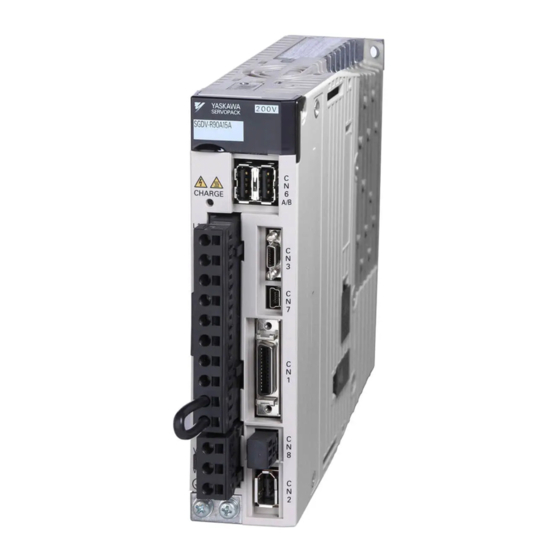
1.2 Nameplate (Ratings) and Model Designation Nameplate (Ratings) and Model Designation Nameplate (Ratings) Example Application Module model number Name Manufacturing number Model Designation SGDV – OS A01 A 6th digit: Design Revision Order Series Σ-V Series SGDV 3rd + 4th + 5th digits: Interface Specifications Interface 1st + 2nd digits: Module Type Code... - Page 26 1 Checking Products...
- Page 27 Specifications This chapter gives an overview and describes the specifications of the Safety Module. 2.1 Overview ..........2-2 2.2 Specifications .
-
Page 28: Overview
2 Specifications Overview The -V-series Safety Module is an Option Module that is connected to a -V-series SERVOPACK. By using the Hard Wire BaseBlock function of the SERVOPACK, the following four safety functions, which are defined in functional safety standards, can be achieved. Function Remarks Safe BaseBlock Function... -
Page 29: Specifications
2.2 Specifications Specifications This table lists the general specifications of the Safety Module. SGDV-01 (analog voltage and pulse train reference model) SGDV-11 (M-II communications reference model) Rotational SGDV-E1 motor (command option attachable type) SGDV-21 (M-III communications reference model) -V Series Applicable SERVOPACK SGDV-05 ... -
Page 30: Part Names
2 Specifications Part Names The following figure shows the part names of the Safety Module. I/O connector for the Safety Function A (CN21) I/O connector for the Safety Function B (CN22) Note: For the names of the SERVOPACK parts, refer to the user’s manual for the SERVOPACK being used. -
Page 31: Internal Block Diagram
2.4 Internal Block Diagram Internal Block Diagram This figure shows a typical internal block diagram. Block A Safety function Power module Block B... - Page 32 2 Specifications...
- Page 33 SERVOPACK Installation This chapter describes how to install the SERVOPACK. 3.1 SERVOPACK Installation Environment and Harmonized Standards ..3-2 3.1.1 Installation Environment ..........3-2 3.1.2 Installation Conditions for Harmonized Standards .
-
Page 34: Chapter 3 Servopack Installation
3 SERVOPACK Installation 3.1.1 Installation Environment SERVOPACK Installation Environment and Harmonized Standards SERVOPACK installation environment and harmonized standards are as follows. 3.1.1 Installation Environment Surrounding air temperature: 0 to 55C Ambient humidity: 90% RH or less (with no condensation) ... -
Page 35: Servopack Installation
3.2 SERVOPACK Installation SERVOPACK Installation 3.2.1 Orientation The SERVOPACK is available in models that are base-mounted, models that are rack-mounted, and models that are duct-ventilated. In any case, mount the SERVOPACK with a vertical orientation. Firmly secure the SERVOPACK to the mounting surface, using either two or four mounting holes depending on the SERVOPACK capacity. -
Page 36: Installation Standards
3 SERVOPACK Installation 3.2.2 Installation Standards 3.2.2 Installation Standards Observe the standards for mounting SERVOPACKs in control panels, including those for the mounting SER- VOPACKs side by side in one control panel as shown in the following illustration. • SERVOPACK Mounting Orientation Mount the SERVOPACK vertically to the wall, with the front panel (the side with the panel operator display) facing out. -
Page 37: Emc Installation Conditions
Refer to this section for other SERVOPACK models such as the rack-mounted types as well. This section describes the EMC installation conditions satisfied in test conditions prepared by Yaskawa. The actual EMC level may differ depending on the actual system’s configuration, wiring, and other condi- tions. - Page 38 3 SERVOPACK Installation 3.3.1 SGDV-0 (Analog Voltage and Pulse Train Reference Model) Three-phase 200 V • SGDV-A0B ( = R70, R90, 1R6, 2R8) + SGDV-OSA01A Shield box Brake Power Supply SERVOPACK Brake U, V, W Power supply: Noise L1, L2, L3 Three-phase filter 200 VAC...
- Page 39 3.3 EMC Installation Conditions Three-phase 200 V • SGDV-A0A ( = R70, R90, 1R6, 2R8, 3R8, 5R5, 7R6) + SGDV-OSA01A Shield box Brake power supply SERVOPACK Brake U, V, W Power supply: Noise L1, L2, L3 filter Three-phase 200 VAC Servomotor One turn Surge...
- Page 40 3 SERVOPACK Installation 3.3.1 SGDV-0 (Analog Voltage and Pulse Train Reference Model) Three-phase 200 V • SGDV-A0A ( = 120) + SGDV-OSA01A Shield box Brake power supply SERVOPACK Brake U, V, W Power supply: Noise L1, L2, L3 filter Three-phase 200 VAC Servomotor One turn...
- Page 41 3.3 EMC Installation Conditions Three-phase 200 V • SGDV-A0A ( = 180, 200, 330) + SGDV-OSA01A Shield box Brake power supply SERVOPACK Brake U, V, W Noise Power supply: L1, L2, L3 filter Three-phase 200 VAC Servomotor One turn Surge L1C, L2C absorber...
- Page 42 3 SERVOPACK Installation 3.3.1 SGDV-0 (Analog Voltage and Pulse Train Reference Model) Three-phase 200 V • SGDV-A0A ( = 470, 550, 590, 780) + SGDV-OSA01A Shield box Brake power Cooling fan supply SERVOPACK Brake U, V, W Noise Power supply: L1, L2, L3 filter Three-phase 200 VAC...
- Page 43 3.3 EMC Installation Conditions Three-phase 400 V • SGDV-D0A ( = 1R9, 3R5, 5R4, 8R4, 120, 170) + SGDV-OSA01A Shield box Power supply: Brake power Noise Single-phase supply filter* 200 VAC Surge SERVOPACK absorber Control Brake power U, V, W 24 V, 0 V supply 24 VDC*...
- Page 44 3 SERVOPACK Installation 3.3.1 SGDV-0 (Analog Voltage and Pulse Train Reference Model) Three-phase 400 V • SGDV-D0A ( = 210, 260, 280, 370) + SGDV-OSA01A Shield box Power supply: Brake power Noise Single-phase supply filter* 200 VAC Surge SERVOPACK Control absorber Brake...
-
Page 45: Sgdv-1 (M-Ii Communications Reference Model)
3.3 EMC Installation Conditions 3.3.2 SGDV-1 (M-II Communications Reference Model) Single-phase 100 V • SGDV-F1A ( = R70, R90, 2R1, 2R8) + SGDV-OSA01A Shield box Brake power supply One turn SERVOPACK Brake U, V, W Power supply: Noise L1, L2 Single-phase 100 VAC filter Servomotor... - Page 46 3 SERVOPACK Installation 3.3.2 SGDV-1 (M-II Communications Reference Model) Three-phase 200 V • SGDV-A1B ( = R70, R90, 1R6, 2R8) + SGDV-OSA01A Shield box Brake Power Supply SERVOPACK Brake U, V, W Power supply: Noise L1, L2, L3 Three-phase filter 200 VAC Servomotor...
- Page 47 3.3 EMC Installation Conditions Three-phase 200 V • SGDV-A1A ( = R70, R90, 1R6, 2R8, 3R8, 5R5, 7R6) + SGDV-OSA01A Shield box Brake power supply SERVOPACK Brake U, V, W Power supply: Noise L1, L2, L3 filter Three-phase 200 VAC Servomotor One turn Surge...
- Page 48 3 SERVOPACK Installation 3.3.2 SGDV-1 (M-II Communications Reference Model) Three-phase 200 V • SGDV-A1A ( = 120) + SGDV-OSA01A Shield box Brake power supply SERVOPACK Brake U, V, W Power supply: Noise L1, L2, L3 filter Three-phase 200 VAC Servomotor One turn Surge...
- Page 49 3.3 EMC Installation Conditions Three-phase 200 V • SGDV-A1A ( = 180, 200, 330) + SGDV-OSA01A Shield box Brake power supply SERVOPACK Brake U, V, W Noise Power supply: L1, L2, L3 filter Three-phase 200 VAC Servomotor One turn Surge L1C, L2C absorber...
- Page 50 3 SERVOPACK Installation 3.3.2 SGDV-1 (M-II Communications Reference Model) Three-phase 200 V • SGDV-A1A ( = 470, 550, 590, 780) + SGDV-OSA01A Shield box Brake power Cooling fan supply SERVOPACK Brake U, V, W Noise Power supply: L1, L2, L3 filter Three-phase 200 VAC Servomotor...
- Page 51 3.3 EMC Installation Conditions Three-phase 400 V • SGDV-D1A ( = 1R9, 3R5, 5R4, 8R4, 120, 170) + SGDV-OSA01A Shield box Power supply: Brake power Noise Single-phase supply filter* 200 VAC Surge SERVOPACK absorber Control Brake power U, V, W 24 V, 0 V supply 24 VDC*...
- Page 52 3 SERVOPACK Installation 3.3.2 SGDV-1 (M-II Communications Reference Model) Three-phase 400 V • SGDV-D1A ( = 210, 260, 280, 370) + SGDV-OSA01A Shield box Power supply: Brake power Noise Single-phase supply filter* 200 VAC Surge SERVOPACK Control absorber Brake power U, V, W 24 V, 0 V...
-
Page 53: Sgdv-2 (M-Iii Communications Reference Model)
3.3 EMC Installation Conditions 3.3.3 SGDV-2 (M-III Communications Reference Model) Single-phase 100 V • SGDV-F2A ( = R70, R90, 2R1, 2R8) + SGDV-OSA01A Shield box Brake Power Supply One turn SERVOPACK Brake U, V, W Noise Power supply: L1, L2 filter Single-phase 100 VAC Servomotor... - Page 54 3 SERVOPACK Installation 3.3.3 SGDV-2 (M-III Communications Reference Model) Three-phase 200 V • SGDV-A2B ( = R70, R90, 2R6, 2R8) + SGDV-OSA01A Shield box Brake Power Supply SERVOPACK Brake U, V, W Power supply: Noise L1, L2, L3 Three-phase filter Servomotor 200 VAC...
- Page 55 3.3 EMC Installation Conditions Three-phase 200 V • SGDV-A2A ( =R70, R90, 1R6, 2R8, 3R8, 5R5, 7R6) + SGDV-OSA01A Shield box Brake Power Supply SERVOPACK Brake U, V, W Noise Power supply: L1, L2, L3 filter Three-phase 200 VAC Servomotor One turn Surge...
- Page 56 3 SERVOPACK Installation 3.3.3 SGDV-2 (M-III Communications Reference Model) Three-phase 200 V • SGDV-A2A ( = 120) + SGDV-OSA01A Shield box Brake Power Supply SERVOPACK Brake U, V, W Noise Power supply: L1, L2, L3 filter Three-phase 200 VAC Servomotor One turn Surge...
- Page 57 3.3 EMC Installation Conditions Three-phase 200 V • SGDV-A2A ( = 180, 200, 330) + SGDV-OSA01A Shield box Brake Power Supply SERVOPACK Brake U, V, W Noise Power supply: L1, L2, L3 filter Three-phase 200 VAC Servomotor One turn Surge L1C, L2C absorber...
- Page 58 3 SERVOPACK Installation 3.3.3 SGDV-2 (M-III Communications Reference Model) Three-phase 200 V • SGDV-A2A ( = 470, 550, 590, 780) + SGDV-OSA01A Shield box Brake Power Cooling fan Supply SERVOPACK Brake U, V, W Noise Power supply: L1, L2, L3 filter Three-phase 200 VAC Servomotor...
- Page 59 3.3 EMC Installation Conditions Three-phase 400 V • SGDV-D2A ( = 1R9, 3R5, 5R4, 8R4, 120, 170) + SGDV-OSA01A Shield box Power supply: Brake Power Single-phase Supply 200 VAC SERVOPACK Control Brake Surge Noise power U, V, W 24 V, 0 V absorber filter* 2 supply...
- Page 60 3 SERVOPACK Installation 3.3.3 SGDV-2 (M-III Communications Reference Model) Three-phase 400 V • SGDV-D2A ( = 210, 260, 280, 370) + SGDV-OSA01A Shield box Power supply: Brake Power Single-phase Supply 200 VAC SERVOPACK Control Brake Surge Noise U, V, W power 24 V, 0 V absorber...
-
Page 61: Sgdv-EA (Command Option Attachable Type)
3.3 EMC Installation Conditions 3.3.4 SGDV-EA (Command Option Attachable Type) Single-phase 100 V • SGDV-FEA ( = R70, R90, 2R1, 2R8) + SGDV-OSA01A Shield box Brake power supply One turn SERVOPACK Brake U, V, W Power supply: Noise L1, L2 Single-phase 100 VAC filter Servomotor... - Page 62 3 SERVOPACK Installation 3.3.4 SGDV-EA (Command Option Attachable Type) Three-phase 200 V • SGDV-AEA ( = R70, R90, 1R6, 2R8, 3R8, 5R5, 7R6) + SGDV-OSA01A Shield box Brake power supply SERVOPACK Brake U, V, W Noise Power supply: L1, L2, L3 filter Three-phase 200 VAC Servomotor...
- Page 63 3.3 EMC Installation Conditions Three-phase 200 V • SGDV-AEA ( = 120) + SGDV-OSA01A Shield box Brake power supply SERVOPACK Brake U, V, W Noise Power supply: L1, L2, L3 Three-phase 200 VAC filter Servomotor One turn Surge L1C, L2C absorber Encoder Safety...
- Page 64 3 SERVOPACK Installation 3.3.4 SGDV-EA (Command Option Attachable Type) Three-phase 200 V • SGDV-AEA ( = 180, 200, 330) + SGDV-OSA01A Shield box Brake power supply SERVOPACK Brake U, V, W Noise Power supply: L1, L2, L3 filter Three-phase 200 VAC Servomotor One turn Surge...
- Page 65 3.3 EMC Installation Conditions Three-phase 200 V • SGDV-AEA ( = 470, 550, 590, 780) + SGDV-OSA01A Shield box Brake power Cooling fan supply SERVOPACK Brake U, V, W Noise Power supply: L1, L2, L3 filter Three-phase 200 VAC Servomotor Surge L1C, L2C...
- Page 66 3 SERVOPACK Installation 3.3.4 SGDV-EA (Command Option Attachable Type) Three-phase 400 V • SGDV-DEA ( = 1R9, 3R5, 5R4, 8R4, 120, 170) + SGDV-OSA01A Shield box Power supply: Brake power Noise Single-phase supply filter* 200 VAC Surge SERVOPACK absorber Control Brake power...
- Page 67 3.3 EMC Installation Conditions Three-phase 400 V • SGDV-DEA ( = 210, 260, 280, 370) + SGDV-OSA01A Shield box Power supply: Brake power Noise Single-phase supply filter* 200 VAC Surge SERVOPACK Control absorber Brake power U, V, W 24 V, 0 V supply 24 VDC* Servomotor...
- Page 68 3 SERVOPACK Installation 3.3.4 SGDV-EA (Command Option Attachable Type) Attachment Methods of Ferrite Cores One turn Two turn Cable Cable Ferrite core Ferrite core Recommended Ferrite Core Ferrite Core Model Manufacturer ESD-SR-250 NEC TOKIN Corp. Recommended Noise Filter and Surge Absorber ...
- Page 69 Wiring and Connection This chapter describes an example of how a system is configured using the Safety Module and how the I/O signals are connected. For details on the main circuit, encoders, and regenerative resistors, refer to the following manuals. For more information on safe and stable usage of the servo system, be sure to read the precautions in the sections labelled, “...
-
Page 70: System Configuration Diagram
4 Wiring and Connection System Configuration Diagram An example of system configuration using SERVOPACK for MECHATROLINK-II communications refer- ence is shown below. Power supply Three-phase 200 VAC R S T Molded-case circuit breaker (MCCB) Protects the power supply line by shutting the Connect to the circuit OFF when MECHATROLINK-II. -
Page 71: I/O Signal Connections
4.2 I/O Signal Connections I/O Signal Connections This section describes the names and functions of I/O connectors (CN21 and CN22) for the Safety Functions A and B. 4.2.1 Terminal Layout (1) I/O Connector for Safety Function A (CN21) Reference Signal Pin No. -
Page 72: Electrical Specifications And Connections Of Input Circuit
4 Wiring and Connection 4.2.2 Electrical Specifications and Connections of Input Circuit 4.2.2 Electrical Specifications and Connections of Input Circuit This section describes the characteristics of the input signals assigned to the CN21 and CN22 connectors on the Safety Module. (1) Specifications Name Signal... - Page 73 4.2 I/O Signal Connections 4.2.3 of Output Circuit Electrical Specifications and Connections This section describes the characteristics of the output signals assigned to the CN21 and CN22 connectors on the Safety Module. (1) Specifications Name Signal Pin No. Input Status Meaning Safety Function A activates without fault.
-
Page 74: Electrical Specifications And Connections Of Output Circuit
4 Wiring and Connection 4.2.3 Electrical Specifications and Connections of Output Circuit... -
Page 75: Before Starting Operation
Precautions and Basic Settings Required before Starting Operation This chapter describes information that is required before starting operation. Be sure to read the following safety precautions, risk assessment information, limitations, and basic settings before starting operation, and use the Safety Module after properly understanding all of this information. -
Page 76: Safety Precautions For Using The Safety Module
5 Precautions and Basic Settings Required before Starting Operation Safety Precautions for Using the Safety Module Carefully read the following important precautions and observe them when using the Safety Module. WARNING • Installation, disassembly, or repair must be performed only by authorized personnel. Failure to observe this precaution may result in electric shock or injury. -
Page 77: Risk Assessment
5.2 Risk Assessment Risk Assessment When using the Safety Module, be sure to perform risk assessment of the servo system in advance. Make sure that the safety level of the standards is met. For details about the standards, refer to Harmonized Standards at the front of this manual. -
Page 78: Limitations
5 Precautions and Basic Settings Required before Starting Operation 5.3.1 Limitations on Lower Limit of Encoder Output Pulses Limitations When the Safety Module is used, use of Pn212 or Pn281 to control the encoder’s output pulses, test without the motor function, and the external encoder of the SERVOPACK will be restricted. 5.3.1 Limitations on Lower Limit of Encoder Output Pulses When the Safety Module is used, the lower limit for the encoder’s output pulses is restricted. - Page 79 5.3 Limitations Linear Servomotors Pn281: Encoder Output Resolution [edge/pitch] 5 Pn282 (Linear Scale Pitch) [m/pitch] Lower limit of Pn281 [edge/pitch] Pn385 (Motor Max. Speed) [mm/s] Lower Limit of Encoder Output Resolution Lower Limit of Encoder Motor Max. Speed Linear Scale Pitch Output Resolution (Pn281) [mm/s]...
-
Page 80: Limitations On The Use Of The Test Without Motor Function
5 Precautions and Basic Settings Required before Starting Operation 5.3.2 Limitations on the Use of the Test without Motor Function 5.3.2 Limitations on the Use of the Test without Motor Function The test without motor function of the SERVOPACK cannot be used together with the safety functions of the Safety Module. -
Page 81: Basic Settings Required Before Starting Operation
5.4 Basic Settings Required before Starting Operation Basic Settings Required before Starting Operation The basic functions that must be set before starting operation are given below. Step Item Reference Disabling the external encoder Disabling the test without motor function Rotational Motor rotation direction servomotor Setting motor... -
Page 82: Checking The Operation
5 Precautions and Basic Settings Required before Starting Operation Checking the Operation When starting the system or replacing a SERVOPACK for maintenance or inspection purposes, make sure that the relevant External Device Monitor Output Signal turns ON when the redundant Safety Request Input Sig- nals turn OFF. - Page 83 Safety Functions This chapter describes the Safety Functions of the Safety Module. 6.1 Overview ..........6-2 6.2 Common Items .
-
Page 84: Chapter 6 Safety Functions
6 Safety Functions Overview The Safety Module is equipped with four functions to provide machine safety. These functions reduce risks during usage of the machine by protecting people from hazardous operations of movable machine parts. The stopping function that is defined in functional safety standards can be achieved with these four functions. The Safety Module provides the following four safety functions. -
Page 85: Common Items
6.2 Common Items Common Items 6.2.1 Selecting a Safety Function The Safety Module has two safety functions with the same features and these functions can be allocated sepa- rately. Either or both of these safety functions can be used. The setup parameters of safety functions are as follows: Parameter Setting Factory... -
Page 86: Safety Request Input Signals
6 Safety Functions 6.2.2 Safety Request Input Signals 6.2.2 Safety Request Input Signals (1) Safety Request Input Signals Safety Request Input Signals initiate the execution of the safety functions. Safety functions are executed when a Safety Request Input Signal is input. To improve safety, two Safety Request Input Signal channels are allocated to each safety function. - Page 87 6.2 Common Items (4) Error Detection for Safety Request Input Signals The Safety Module monitors the state of redundant Safety Request Input Signals allocated to each safety func- tion to detect errors. The process of error detection is as follows: 1.
- Page 88 6 Safety Functions 6.2.2 Safety Request Input Signals Alarms The following alarms occur if an error is detected in the Safety Request Input Signals. To cancel an alarm, remove the cause of the alarm, and then reset the system. Alarm Alarm No.
-
Page 89: External Device Monitor Output Signals
6.2 Common Items 6.2.3 External Device Monitor Output Signals These signals are output when the following two conditions are met: • The safety function is operating normally. • No malfunction occurs in the safety function. If a malfunction occurs in the safety function when the safety function is operating, this signal will not be out- put.... - Page 90 6 Safety Functions 6.2.3 External Device Monitor Output Signals (2) Selecting Output Conditions The output conditions of the External Device Monitor Output Signals can be selected by using the parameters. Parameter Setting Factory Name Units When Enabled Range Setting EDM Signal Output Selection After resetting the Pc01 –...
- Page 91 6.2 Common Items (3) Output Delay Time The output delay time of the External Device Monitor Output Signals is shown below. Operation Timing Not met Not met Output Conditions External Device Monitor Output Signals td: Output delay time of the External Device Monitor Output Signal (40 ms max.) ...
-
Page 92: Operations After Alarms And Resetting Systems, And While Recalculating Parameters
6 Safety Functions 6.2.4 Operations After Alarms and Resetting Systems, and While Recalculating Parameters 6.2.4 Operations After Alarms and Resetting Systems, and While Recalculating Parameters The Safety Module operates in a different manner after the system is reset, an alarm occurs, or while parame- ters are recalculated. -
Page 93: Safe Baseblock Function (Sbb Function)
6.3 Safe BaseBlock Function (SBB Function) Safe BaseBlock Function (SBB Function) 6.3.1 Basic Operation The Safe BaseBlock Function (hereafter called the SBB function) operates based on Safe Torque Off (STO) function that is defined in IEC 61800-5-2. This function shuts OFF the power supply to the motor by execut- ing the HWBB function of the SERVOPACK according to the safety request input state. -
Page 94: Exceptional Operation
6 Safety Functions 6.3.4 Exceptional Operation (2) Returning Timing When the Servo ON Command Is Not Input Operation Timing Returning conditions Not met Servo ON command SERVOPACK state HWBB state BB state td: Delay time (40 ms max.) When the Servo ON Command Is Input When the safety request input status is ON, the SBB function stops operating. -
Page 95: Related Servopack Functions
6.3 Safe BaseBlock Function (SBB Function) (2) While Recalculating Parameters When parameters are being recalculated, the SBB function is executed according to the Safety Request Input Signal after recalculation of parameters. For details on how to return to normal operation from the HWBB state, refer to 6.3.3 Returning Method. Operation Timing Parameter recalculation request ON (Servo ON... - Page 96 6 Safety Functions 6.3.5 Related SERVOPACK Functions (3) Zero-speed Stopping When the SBB Function is Turned ON (Operating) while Zero-speed Stopping When the SBB function is turned ON while zero-speed stopping (during a GR2 alarm), zero-speed stopping is canceled and the motor is stopped according to the method specified in parameter Pn001.0 (Application Func- tion Select Switch).
- Page 97 6.3 Safe BaseBlock Function (SBB Function) (5) Servo Ready Signal When the SBB function is operating, the Servo Ready Signal turns OFF (i.e., the servo cannot be turned ON) during operation of the SBB function. After returning from the HWBB state, the Servo Ready Signal turns ON (i.e., the servo can be turned ON).
- Page 98 6 Safety Functions 6.3.5 Related SERVOPACK Functions (8) Relationship with MECHATROLINK-III Commands If the SERVOPACK changes to the HWBB state during the execution of any of the following MECHATRO- LINK-III commands, a command warning will occur. A command warning will also occur if a MECHATRO- LINK-III command now being executed is canceled with the CMD_CANCEL (cancellation of move command) control bit.
-
Page 99: Safe Baseblock With Delay Function (Sbb-D Function)
6.4 Safe BaseBlock with Delay Function (SBB-D Function) Safe BaseBlock with Delay Function (SBB-D Function) 6.4.1 Basic Operation The Safety BaseBlock with Delay Function (hereafter called the SBB-D function) operates based on the Safe Stop 1 (SS1) function that is defined in IEC 61800-5-2. This function monitors the deceleration operation (deceleration monitoring) of the motor according to the safety request input state until the time period speci- fied in the parameter elapses, and then shuts OFF the power supply to the motor by executing the HWBB function of the SERVOPACK. -
Page 100: Basic Operation
6 Safety Functions 6.4.1 Basic Operation Operation Timing OFF (Safety Function Safety request Execution Request) input state A Monitoring speed Alarm Motor speed Set Time SBB-D function Deceleration Safe (HWBB) Standby operation state monitoring state Power supply to Supplied Shut OFF motor ALM signal (SERVOPACK CN1) -
Page 101: Settings
6.4 Safe BaseBlock with Delay Function (SBB-D Function) Note 1. The deceleration waiting time (t1) cannot be longer than the deceleration monitoring time (t2). If it is longer, alarm A.EB2 (Safety Module: Parameter Setting Error) will occur. 2. The deceleration waiting monitoring speed (S1) cannot be faster than the Motor Max. Speed. If it is faster, alarm A.EB2 (Safety Module: Parameter Setting Error) will occur. -
Page 102: Related Servopack Functions
6 Safety Functions 6.4.5 Related SERVOPACK Functions 6.4.5 Related SERVOPACK Functions The SERVOPACK functions and operations related to the safe (HWBB) state after deceleration monitoring are the same as that for the SBB function. These are listed below. For details, refer to 6.3.5 Related SERVO- PACK Functions. -
Page 103: Safe Position Monitor With Delay Function (Spm-D Function)
6.5 Safe Position Monitor with Delay Function (SPM-D Function) Safe Position Monitor with Delay Function (SPM-D Function) 6.5.1 Basic Operation The Safe Position Monitor with Delay Function (hereafter called the SPM-D function) operates based on the Safe Stop 2 (SS2) function that is defined in IEC 61800-5-2. This function monitors the deceleration operation (deceleration monitoring) of the motor according to the safety request input state until the time period speci- fied in the parameter elapses, and then switches to position monitoring and monitors the distance that the motor moved to make sure it is within the allowable range. -
Page 104: Basic Operation
6 Safety Functions 6.5.1 Basic Operation Operation Timing Safety request OFF (Safety Function Execution Request) input state Alarm Distance for monitoring Motor position Set Time Reference position SPM-D function Deceleration Safe (HWBB) Standby Position monitoring monitoring state operation state Power supply Supplied Shut OFF to motor... -
Page 105: Settings
6.5 Safe Position Monitor with Delay Function (SPM-D Function) 6.5.2 Settings To use the SPM-D function, make the settings for using the SPM-D function of either Safety Function A or Safety Function B in the parameters. For details on selecting the safety functions, refer to 6.2.1 Selecting a Safety Function. -
Page 106: Related Servopack Functions
6 Safety Functions 6.5.5 Related SERVOPACK Functions 6.5.5 Related SERVOPACK Functions The SERVOPACK functions and operations related to the operation of the SPM-D function are same as that for the SBB-D function. There are listed below. For details, refer to 6.4.5 Related SERVOPACK Functions. •... -
Page 107: Safely Limited Speed With Delay Function (Sls-D Function)
6.6 Safely Limited Speed with Delay Function (SLS-D Function) Safely Limited Speed with Delay Function (SLS-D Function) 6.6.1 Basic Operation The Safely Limited Speed with Delay Function (hereafter called the SLS-D function) operates based on Safely-Limited Speed (SLS) that is defined in IEC 61800-5-2. This function monitors the deceleration opera- tion (deceleration monitoring) of the motor according to the safety request input state until the time period specified in the parameter elapses, and then monitors the motor speed to make sure it is within the allowable range (within a constant speed range). -
Page 108: Basic Operation
6 Safety Functions 6.6.1 Basic Operation Operation during Deceleration Monitoring and Constant-speed Monitoring • Alarms The operation when the motor speed exceeds the monitoring speed during deceleration monitoring and con- stant-speed monitoring is the same as the operation during deceleration monitoring of the SBB-D function. ... -
Page 109: Settings
6.6 Safely Limited Speed with Delay Function (SLS-D Function) 6.6.2 Settings To use the SLS-D function, make the settings for using the SLS-D function of either Safety Function A or Safety Function B in the parameters. For details on the settings of the safety functions, refer to 6.2.1 Selecting a Safety Function. -
Page 110: Related Servopack Functions
6 Safety Functions 6.6.5 Related SERVOPACK Functions 6.6.5 Related SERVOPACK Functions The SERVOPACK functions and operations related to the operation of the SLS-D function are same as that for the SBB-D function. These are listed below. For details, refer to 6.4.5 Related SERVOPACK Functions. •... -
Page 111: Order Of Priority Of Safety Functions
6.7 Order of Priority of Safety Functions Order of Priority of Safety Functions Safety functions can be set individually for Safety Function A and Safety Function B. Two safety functions may be executed under the following two conditions: • If one of the two safety functions is changed to the safe (HWBB) state, the other function will also be changed to the safe (HWBB) state. - Page 112 6 Safety Functions Reference Position When the SPM-D Function Is Set for Both Safety Functions When the SPM-D function is set for Safety Function A and Safety Function B, the motor position set in the safety function that is the first to reach the position monitoring state is treated as the reference position of Safety Function A and Safety Function B.
-
Page 113: Application Example Of Safety Functions
6.8 Application Example of Safety Functions Application Example of Safety Functions An application example of the safety functions is described below. (1) Connection Example A connection example in which a Safety Module is used and the safety functions are set to operate under the following conditions is described here. - Page 114 6 Safety Functions (2) Operation Example Safety Function A <When Door Switch Is Closed> The X1 signal of the Safety Controller is OFF and the S14 and the S24 signals are ON. Signals /SRI-A1 and /SRI-A2 both are ON and Safety Function A (SLS-D function) does not operate. Normal operation is exe- cuted.
-
Page 115: Application Example Of Safety Functions
6.8 Application Example of Safety Functions Safety Function B <When the Emergency Stop Switch Is Not Pressed> The X1 signal of the Safety Controller is OFF and the S14 and the S24 signals are ON. Signals /SRI-B1 and /SRI-B2 are both ON and Safety Function B (SBB-D function) does not operate. - Page 116 6 Safety Functions 6.6.5 Related SERVOPACK Functions 6-34...
- Page 117 Setting Parameters This chapter describes the parameters related to the safety functions of the Safety Module. For the parameters of the SERVOPACK, refer to the user’s manual of the SERVOPACK being used. 7.1 Types of Parameters ......... 7-2 7.2 Safety-related Module Parameters .
-
Page 118: Chapter 7 Setting Parameters
7 Setting Parameters Types of Parameters To operate the Safety Module, the parameters must be set according to the servo system being used. There are two types of Safety Module parameters, as described in the following table. Parameters Overview These parameters are used to set safety functions. These parameters are used Safety-related Module Parameters only for the Safety Module. -
Page 119: Safety-Related Module Parameters
7.2 Safety-related Module Parameters Safety-related Module Parameters 7.2.1 Overview The safety-related module parameters are used to set the safety functions of the Safety Module. The safety- related module parameters are listed in the following table. Parameter No. Name Pc00 Safety Function Selection Switch Pc01 EDM Signal Output Selection Switch Pc10... -
Page 120: Operation Procedures
7 Setting Parameters 7.2.2 Operation Procedures 7.2.2 Operation Procedures The procedures for referencing, editing, and initializing the safety-related module parameters are given in this section. (1) Referencing Parameters Start Display the Utility Function Main Menu. Utility Function Fn041 Reference: 8.3 Safety-related Module Enter a parameter number. - Page 121 7.2 Safety-related Module Parameters (2) Editing Parameters Start Utility Function Fn040 Change the access Reference: 8.2 Safety Option Module Access Mode Setting mode to Edit Mode. (Fn040). Utility Function Fn041 Change the setting Reference: 8.3 Safety-related Module Parameter Setting (Fn041). of the parameter.
- Page 122 7 Setting Parameters 7.2.2 Operation Procedures (3) Initializing Parameters Start Utility Function Fn040 Change the access mode Reference: 8.2 Safety Option Module Access Mode Setting (Fn040). to Edit Mode. Utility Function Fn043 Change the parameters to Reference: 8.5 Safety Option Module Initializing the factory settings.
-
Page 123: Safety-Related Servo Parameters
7.3 Safety-related Servo Parameters Safety-related Servo Parameters 7.3.1 Overview Safety-related servo parameters contain information about the safety functions of the SERVOPACK and servomotor and are managed by the Safety Module. This information is maintained in the SERVOPACK, but it is also managed in the Safety Module with different parameter numbers. To change a safety-related servo parameter, change the corresponding SERVOPACK parameter, and then update the parameters with the utility function Fn042. -
Page 124: Operation Procedures
7 Setting Parameters 7.3.2 Operation Procedures 7.3.2 Operation Procedures The procedures for referencing and updating the safety-related servo parameters are given in this section. The safety-related servo parameters cannot be edited. (1) Referencing Parameters Start Display the Utility Function Main Menu. Utility Function Fn041 Reference: 8.3 Safety-related Module Enter a parameter number. - Page 125 7.3 Safety-related Servo Parameters (2) Updating Parameters Start Change the SERVOPACK param- For details, refer to the user's manual of the eter that corresponds to the safety- SERVOPACK being used. related servo parameter, or change the connected servomotor. Either reset the system or recalculate the parameter.
- Page 126 7 Setting Parameters 7.3.2 Operation Procedures 7-10...
- Page 127 Utility Functions This chapter describes the utility functions related to the Safety Module. For details on the utility functions of the SERVOPACK, refer to the user’s manual of the SERVOPACK being used. 8.1 List of Utility Functions ........8-2 8.2 Safety Option Module Access Mode Setting (Fn040) .
-
Page 128: List Of Utility Functions
8 Utility Functions List of Utility Functions When the Safety Module is connected to the SEROVOPACK, the following utility functions can be used. These functions are used when operating the parameters of the safety Module and referring the informations related to the Safety Module. Function Function Reference... -
Page 129: Safety Option Module Access Mode Setting (Fn040)
8.2 Safety Option Module Access Mode Setting (Fn040) Safety Option Module Access Mode Setting (Fn040) 8.2.1 Overview To change the parameters of the Safety Module, the access mode must be changed to Edit Mode. The access mode can be switched using this function. ... - Page 130 8 Utility Functions 8.2.2 Operation Procedures (2) Operating from the Panel Operator The procedure for operating from the panel operator is shown below. Step Display After Operation Keys Operation Press the MODE/SET Key to select the utility function mode. MODE/SET DATA/ Press the UP or DOWN Key to display “Fn040.”...
-
Page 131: Safety-Related Module Parameter Setting (Fn041)
8.3 Safety-related Module Parameter Setting (Fn041) Safety-related Module Parameter Setting (Fn041) 8.3.1 Overview This function is used to change the safety-related module parameters. Preparation Before setting the safety-related module parameters check the following: • The servo must be OFF. •... -
Page 132: Operation Procedures
8 Utility Functions 8.3.2 Operation Procedures 8.3.2 Operation Procedures (1) Operating from the Digital Operator The procedure for operating from the digital operator is shown below. Step Display After Operation Keys Operation − F U N C T I O N − Press the Key to display the main menu of utility F n 0 4 0 S O M M o d e S e t... - Page 133 8.3 Safety-related Module Parameter Setting (Fn041) (2) Operating from the Panel Operator The procedure for operating from the panel operator is shown below. Step Display After Operation Keys Operation Press the MODE/SET Key to select the utility function mode. MODE/SET DATA/ Press the UP or DOWN Key to display “Fn041.”...
-
Page 134: Safety-Related Servo Parameter Updating (Fn042)
8 Utility Functions 8.4.1 Overview Safety-related Servo Parameter Updating (Fn042) 8.4.1 Overview The settings of SERVOPACK parameters related to the safety functions are managed in the Safety Module. These parameters are called safety-related servo parameters. This function is used to copy the settings of SERVOPACK parameters related to the safety functions to safety- related servo parameters maintained in the Safety Module. - Page 135 8.4 Safety-related Servo Parameter Updating (Fn042) (cont’d) Step Display After Operation Keys Operation Press the Key to update the safety-related servo parameter. When the parameter has been updated, “DONE” flashes in the status display for approx. one second, and the display returns to the parameter check screen. Repeat the operation in Step 3 to 4 and update all the mismatched parameters.
- Page 136 8 Utility Functions 8.4.2 Operation Procedures (2) Operating from the Panel Operator The procedure for operating from the panel operator is shown below. Step Display After Operation Keys Operation Press the MODE/SET Key to select the utility function mode. MODE/SET DATA/ Press the UP or DOWN Key to display “Fn042.”...
- Page 137 8.4 Safety-related Servo Parameter Updating (Fn042) (cont’d) Step Display After Operation Keys Operation Press the DATA/SHIFT Key for at least one second to display the screen on the left. MODE/SET DATA/ Press the DATA/SHIFT Key for at least one second to display the screen on the left.
-
Page 138: Safety Option Module Initializing Parameter Setting (Fn043)
8 Utility Functions 8.5.1 Overview Safety Option Module Initializing Parameter Setting (Fn043) 8.5.1 Overview This function initializes the parameters of the Safety Module to the factory settings. This function is used if the Safety Module parameters are to be initialized to the factory settings from the current settings, or if consis- tency of parameters cannot be achieved due to a memory error in the Safety Module. - Page 139 8.5 Safety Option Module Initializing Parameter Setting (Fn043) (cont’d) Step Display After Operation Keys Operation − F U N C T I O N − F n 0 4 1 S O M P r m E d i t Press the Key to return to the main menu of F n 0 4 2 S O M P r m U p d...
-
Page 140: Safety Option Module Setup Alarm Clear (Fn044)
8 Utility Functions 8.6.1 Overview Safety Option Module Setup Alarm Clear (Fn044) 8.6.1 Overview This function clears the cause of the Safety Module: Confirmation Alarm (A.EC0). This alarm occurs in the following cases: • The system was reset or parameters were recalculated after the combination of the SERVOPACK and Safety Module was changed. -
Page 141: Operation Procedures
8.6 Safety Option Module Setup Alarm Clear (Fn044) 8.6.2 Operation Procedures Operating from the Digital Operator The procedure for operating from the digital operator is shown below. Step Display After Operation Keys Operation − F U N C T I O N − A . - Page 142 8 Utility Functions 8.6.2 Operation Procedures (2) Operating from the Panel Operator The procedure for operating from the panel operator is shown below. Step Display After Operation Keys Operation Press the MODE/SET Key to select the utility function mode. MODE/SET DATA/ Press the UP or DOWN Key to display “Fn044.”...
-
Page 143: Related Utility Functions
8.7 Related Utility Functions Related Utility Functions When using the Safety Module, the following information about the Safety Module is added to the utility functions used in the SERVOPACK. For details on these functions, refer to the user’s manual of the SERVO- PACK being used. - Page 144 8 Utility Functions 8.7.3 Display of SERVOPACK and Servomotor ID (Fn01E) 8-18...
- Page 145 Monitor Mode This chapter describes the monitor mode that is used when a Safety Module is connected to the SERVOPACK. 9.1 Overview ..........9-2 9.1.1 List of Monitor Modes .
-
Page 146: Overview
9 Monitor Mode 9.1.1 List of Monitor Modes Overview The Monitor Mode is used to display the operating status of the SERVOPACK or Safety Module. When a Safety Module is connected to the SERVOPACK, the items related to the Safety Module are added to the mon- itor mode displays of the SERVOPACK. -
Page 147: Status Display
9.1 Overview 9.1.2 Status Display The operating status of the safety functions can be checked from the digital operator, or panel operator dis- plays. A safety function has the following operating states: • Deceleration monitoring • Safe state • Safe (HWBB) state (1) Displaying the Status on the Digital Operator When a digital operator is connected, the SERVOPACK status is displayed at the top left of the display screen. - Page 148 9 Monitor Mode 9.1.2 Status Display (2) Displaying the Status on the Panel Deceleration Monitoring During deceleration monitoring, the panel display is as shown below. SERVOPACK Display Flashing Analog voltage and pulse train reference model • M-II communications reference model Flashing •...
-
Page 149: Monitoring From The Panel Operator And Digital Operator
9.2 Monitoring from the Panel Operator and Digital Operator Monitoring from the Panel Operator and Digital Operator This section describes the contents displayed when information related to the safety functions is checked on the panel operator and digital operator. For details on how to perform operations with the panel operator and Digital Operator, refer to the following manuals: •... -
Page 150: Safety Module System Status (Un018)
9 Monitor Mode 9.2.3 Safety Module System Status (Un018) (cont’d) Parameter Display Name Unit Attribute – Safety Function B Safe Safe state – Safety Function B HWBB HWBB function is operating. Reserved – – The operating status of one safety function is affected by the operating status of the other safety function. The relationship between the operating status of the safety functions and the monitor display is described below. -
Page 151: Time Until Arrival At Safety Speed (Un019 And Un01A)
9.2 Monitoring from the Panel Operator and Digital Operator 9.2.4 Time until Arrival at Safety Speed (Un019 and Un01A) This monitor mode displays the time period until the motor reaches a safe speed after the safety request signal is input. Parameter Name Unit... -
Page 152: Active Mode Reference Speed (Un01B)
9 Monitor Mode 9.2.5 Active Mode Reference Speed (Un01B) 9.2.5 Active Mode Reference Speed (Un01B) This monitor mode displays the internal speed reference of the SERVOPACK that uses the Active Mode Func- tion. Parameter Name Unit Remarks Rotational motor: Active Mode Reference Un01B Initial display after system reset: 0 Speed... -
Page 153: Monitoring Over The Network
9.3 Monitoring Over the Network Monitoring Over the Network In a SERVOPACK for use with MECHATROLINK-II communications reference or MECHATROLINK-III communications reference, monitoring can be performed via MECHATROLINK-II communications or MECHATROLINK-III communications. In a SERVOPACK for use with the Command Option Module, mon- itoring can be performed over the field network of the Command Option Module. -
Page 154: Servopack For Use With Mechatrolink-Iii Communications Reference
9 Monitor Mode 9.3.2 SERVOPACK for Use with MECHATROLINK-III Communications Reference 9.3.2 SERVOPACK for Use with MECHATROLINK-III Communications Reference When Option Monitor 1 or 2 is allocated to MONITOR 1, 2, 3, or 4 in the Monitor Selection (SEL_MON1/2/ 3/4) Field, the I/O signals of the Safety Module and the operating state of the safety functions can be moni- tored via MECHATROLINK-III communications when a specified value is set in the following parameters. - Page 155 Active Mode Function This chapter describes the Active Mode Function, which is an additional function of the SERVOPACK available when used with the Safety Module. 10.1 Overview ..........10-2 10.2 Basic Functions .
-
Page 156: Chapter 10 Active Mode Function
10 Active Mode Function 10.1 Overview Active Mode Function is used to stop the motor according to the internal deceleration reference of the SER- VOPACK that is set in the parameters, when the Safety Request Input Signal turns OFF. Independent deceler- ation references can be set for Safety Function A and Safety Function B. -
Page 157: Internal Deceleration References
10.2 Basic Functions 10.2.1 Internal Deceleration References The parameters for the internal deceleration references in Active Mode Function are as follows: Operation Timing OFF (Safety Function Operation Request) Safety Request Input Signal Internal deceleration reference Pn622 or Pn623 Pn624 Active Mode ON Signal Parameter Setting Factory... -
Page 158: Position Error Level For Releasing Active Mode
10 Active Mode Function 10.2.3 Position Error Level for Releasing Active Mode 10.2.3 Position Error Level for Releasing Active Mode The Position Error Level for Releasing Active Mode prevents the motor from moving unexpectedly when position control is used as the control method and Active Mode Function is canceled. Besides the position reference from the host controller, Active Mode Function controls the motor based on the deceleration reference from the SERVOPACK. -
Page 159: Speed Reference Level For Releasing Active Mode
10.2 Basic Functions 10.2.4 Speed Reference Level for Releasing Active Mode The Speed Reference Level for Releasing Active Mode is used to prevent the sudden operation of the motor when Active Mode Function is canceled in speed control mode. Besides the speed reference from the host controller, Active Mode Function controls the motor based on the deceleration reference from the SERVO- PACK. -
Page 160: Monitoring Active Mode Function
10 Active Mode Function 10.2.5 Monitoring Active Mode Function 10.2.5 Monitoring Active Mode Function Whether Active Mode Function is operating can be monitored by the following methods: • All SERVOPACKs: Allocating the Active Mode output signal (/ACT_MOD) to CN1. • M-II communications reference model: Using the I/O monitor (IO_MON) field. •... - Page 161 10.2 Basic Functions (2) MECHATROLINK-II I/O Monitor (IO_MON) Field If the Active Mode ON Signal is allocated to CN1 in a SERVOPACK with MECHATROLINK-II Communi- cations Reference, the operating state of Active Mode Function can be monitored in the I/O monitor field. The allocation of monitor information and information on the I/O monitor (IO_MON) field are given below.
- Page 162 10 Active Mode Function 10.2.5 Monitoring Active Mode Function Monitor Information Allocation Parameter Factory When Name Setting Range Units Setting Enabled SVCMD_IO (output signal moni- Pn868 0000 to 1717 – n.0000 Immediately tor) Allocation 1 SVCMD_IO (output signal moni- Pn869 0000 to 1717 –...
-
Page 163: Settings
10.3 Settings 10.3 Settings This section describes the setup parameters of Active Mode Function. Parameter Setting Factory Name Units When Enabled Range Setting After resetting the sys- Application Switch for Safety – – 0000 tem or are recalculat- Function ing parameters Selection of Active Mode for Safety Function A Disabled Enabled... -
Page 164: Returning Method
10 Active Mode Function 10.4.1 Returning Conditions 10.4 Returning Method 10.4.1 Returning Conditions When the motor stops due to the operation of Active Mode Function, Active Mode Function can be canceled to return to the normal operation when all of the following conditions are met. •... - Page 165 10.4 Returning Method (2) Position Control Mode Operation Timing OFF (Safety Function Operation Request) Safety Request Input Signal Host controller reference Internal deceleration reference Deceleration Pn625 to a stop Active Mode ON Signal Host controller Operating Standby Returning Operating Triggered by the state of the Active Mode ON Signal Pn625: Active Mode Hold Time •...
-
Page 166: Servopack For Use With Mechatrolink-Ii Communications Reference
10 Active Mode Function 10.4.3 SERVOPACK for Use with MECHATROLINK-II Communications Reference 10.4.3 SERVOPACK for Use with MECHATROLINK-II Communications Reference (1) Speed Control Mode Operation Timing OFF (Safety Function Operation Request) Safety Request Input Signal Host controller reference Internal deceleration reference Deceleration Pn625... - Page 167 10.4 Returning Method (2) Position Control Mode Operation Timing OFF (Safety Function Operation Request) Safety Request Input Signal Host controller reference Internal deceleration reference Deceleration Pn625 to a stop Active Mode ON Signal Host controller Operating Standby Operating Triggered by the state of the Active Mode ON Signal Pn625: Active Mode Hold Time •...
-
Page 168: Servopack For Use With Mechatrolink-Iii Communications Reference
10 Active Mode Function 10.4.4 SERVOPACK for Use with MECHATROLINK-III Communications Reference 10.4.4 SERVOPACK for Use with MECHATROLINK-III Communications Reference (1) Speed Control Mode Operation Timing OFF (Safety Function Operation Request) Safety Request Input Signal Host controller reference Internal deceleration reference Deceleration Pn625... -
Page 169: Servopack For Use With Command Option Module
10.4 Returning Method (2) Position Control Mode Operation Timing Safety Request Input Signal OFF (Safety Function Operation Request) Host controller reference Internal deceleration reference Deceleration Pn625 to a stop Active Mode ON Signal Host controller Operating Standby Operating Triggered by the state of the Active Mode ON Signal Pn625: Active Mode Hold Time •... -
Page 170: Exceptional Operation
10 Active Mode Function 10.5 Exceptional Operation After Resetting the System After the system is reset in Active Mode Function, Active Mode Function stops and the servo system is restarted. While Recalculating Parameters When parameters are being recalculated in Active Mode Function, Active Mode Function stops. For SERVOPACKs with the MECHATROLINK-III communications reference, however, a command warning will be issued and parameters will not be recalculated if recalculation of parameters is attempted with the CONFIG command during a servo ON state. -
Page 171: Related Servopack Functions
10.6 Related SERVOPACK Functions 10.6 Related SERVOPACK Functions The SERVOPACK functions related to the operation of the Active Mode Function are described below. For details, refer to the user's manual of the SERVOPACK being used. • Utility functions • Overtravel •... -
Page 172: Overtravel
10 Active Mode Function 10.6.2 Overtravel 10.6.2 Overtravel If the overtravel function is operated in Active Mode Function, the SERVOPACK operations change as fol- lows: • The internal deceleration reference of Active Mode Function is stopped and the overtravel function is used to slow the motor. -
Page 173: Chapter 11 Troubleshooting
Troubleshooting This chapter describes the alarms that can occur in the Safety Module and the methods of clearing these alarms. For details on the alarms that occur in the SERVOPACK and the methods of clearing the alarms, refer to the user’s manual of the SERVOPACK being used. 11.1 List of Alarms . -
Page 174: List Of Alarms
11 Troubleshooting 11.1 List of Alarms A list of alarms occurring in the Safety Module is shown below. Alarm Alarm Alarm Name Alarm Details Code Reset Safety Option Module A.E71 The Safety Option Module could not be detected. Detection Failure Safety Option Module A Safety Option Module that is not supported by the SER- A.E74... -
Page 175: Troubleshooting Of Alarms
11.2 Troubleshooting of Alarms 11.2 Troubleshooting of Alarms Refer to the following table to identify the cause of an alarm and the action to be taken. Contact your Yaskawa representative if the problem cannot be solved by the described corrective action. - Page 176 11 Troubleshooting (cont’d) Alarm Alarm Name Cause Investigative Action Corrective Action When the safety func- tions are used: • Remove the external encoder. • Set Pn002.3 (External Encoder Usage) to 0, The settings of the safety and then execute functions do not conform Check the set values of Fn042 (Safety-related to the settings of the...
- Page 177 11.2 Troubleshooting of Alarms (cont’d) Alarm Alarm Name Cause Investigative Action Corrective Action • Restart the system. • Remove the Safety Module and then install Safety Module: An error occurred in the it again. A.EB4 Feedback Data position data of the –...
- Page 178 11 Troubleshooting (cont’d) Alarm Alarm Name Cause Investigative Action Corrective Action A Safety-related Module Parameter was changed. Fn042 (Safety-related • Restart the system. Safety Module: Servo Parameter Updat- A.EB9 Parameter Change ing) was executed. – • Recalculate the param- Alarm eters.
- Page 179 Appendix This chapter describes three parameters and also devices that can be used with the Safety Module. For details on these parameters related to SERVOPACKs, refer to the user's manual of the SERVOPACK being used. 12.1 Safety-related Module Parameters ......12-2 12.2 Safety-related Servo Parameters .
-
Page 180: Safety-Related Module Parameters
12 Appendix 12.1 Safety-related Module Parameters The table lists the parameters of the Safety Module. Parameter Setting Factory Name Units When Enabled Range Setting Safety Function Selection Switch – – 0002 After resetting the system 4th 3rd 2nd 1st digit digit digit digit n. - Page 181 12.1 Safety-related Module Parameters (cont’d) Parameter Setting Factory Name Units When Enabled Range Setting -1 0 to 10000 Rotational motor: min Pc14 Limited Constant Speed A After resetting the system Linear motor: mm/s Pc15 to Reserved (Do not change.) Pc1F Pc20 Deceleration Waiting Time B 0 to 10000...
-
Page 182: Safety-Related Servo Parameters
12 Appendix 12.2 Safety-related Servo Parameters Parameter Setting Factory Name Units When Enabled Range Setting Motor Setting Switch – – 0000 After resetting the system 4th 3rd 2nd 1st digit digit digit digit n. Motor Type Setting Rotational motor Linear motor Pc50... - Page 183 12.2 Safety-related Servo Parameters (cont’d) Parameter Setting Factory Name Units When Enabled Range Setting Pc60 Encoder Resolution – After resetting the system Rotational motor: pulse/rev Encoder Output Pulses/ Pc61 – 2048 After resetting the system Encoder Output Resolution Linear motor: edge/pitch -1...
-
Page 184: Parameters Related Active Mode Function
12 Appendix 12.3 Parameters Related Active Mode Function Parameter Factory Name Setting Range Units When Enabled Setting After resetting the Output Signal Selection 7 – – 0000 system or recalculating parameters Active Mode ON Signal Mapping Disabled Analog voltage and pulse train reference model:CN1-25/(26) M-II communications reference model, M-III communications reference model, and command option attachable type:CN1-1/(2) Analog voltage and pulse train reference model:CN1-27/(28) -
Page 185: Device Combinations
12.4 Device Combinations 12.4 Device Combinations Only the models of SERVOPACKs, rotational servomotors and serial converter units listed here can be used in combination with the Safety Module. 12.4.1 SERVOPACKs SERVOPACK Models SGDV-01A Rotational motor SGDV-01B Analog voltage and pulse train reference model SGDV-05A Linear motor SGDV-05B... -
Page 186: Servomotors
12 Appendix 12.4.2 Servomotors (cont’d) Rotational Servomotor Models SGMCS-02B SGMCS-05B SGMCS-07B SGMCS-04C SGMCS-10C SGMCS-14C SGMCS-08D SGMCS-17D SGMCS SGMCS-25D (Direct Drive) SGMCS-16E SGMCS-35E SGMCS-45M SGMCS-80M SGMCS-80N SGMCS-1AM SGMCS-1EN SGMCS-2ZN SGMSV-10A SGMSV-15A SGMSV-20A SGMSV-25A SGMSV-30A SGMSV-40A SGMSV-50A SGMSV (Low inertia, medium capacity) SGMSV-70A 3000 min SGMSV-10D... -
Page 187: Serial Converter Units
12.4 Device Combinations (cont’d) Rotational Servomotor Models SGMGV-03A SGMGV-05A SGMGV-09A SGMGV-13A SGMGV-20A SGMGV-30A SGMGV-44A SGMGV-55A SGMGV-75A SGMGV-1AA SGMGV SGMGV-1EA (Medium inertia, medium capacity) SGMGV-03D 1500 min SGMGV-05D SGMGV-09D SGMGV-13D SGMGV-20D SGMGV-30D SGMGV-44D SGMGV-55D SGMGV-75D SGMGV-1AD SGMGV-1ED Note: For details of rotational servomotors, refer toΣ-V Series Product Catalog (KAEP S800000 42). Any model of linear servomotor can be used with the Safety Module. -
Page 188: Index
Index Index input signal for Safety Function A - - - - - - - - - - - - - - - - - - - - - - 4-3 Safety Request Input Signal A1 - - - - - - - - - - - - - - - - - - - - - 4-3 Safety Request Input Signal A2 - - - - - - - - - - - - - - - - - - - - - 4-3 input signal for Safety Function B - - - - - - - - - - - - - - - - - - - - - - 4-3 Safety Request Input Signal B1 - - - - - - - - - - - - - - - - - - - - - 4-3... - Page 189 Index Safe Position Monitor with Delay Function - - - - - - - - - - - - xvii, 6-21 SLS-D function - - - - - - - - - - - - - - - - - - - - - - - - - - - - - - xvii, 6-25 basic operation - - - - - - - - - - - - - - - - - - - - - - - - - - - - - - - 6-21 basic operation - - - - - - - - - - - - - - - - - - - - - - - - - - - - - - - 6-25 exceptional operation - - - - - - - - - - - - - - - - - - - - - - - - - - 6-23...
-
Page 190: Revision History
Revision History The revision dates and numbers of the revised manuals are given on the bottom of the back cover. MANUAL NO. SIEP C720829 06A Published in Japan June 2011 10-4 0 - 1 WEB revision number Revision number Date of publication Date of original publication... - Page 192 Phone 81-4-2962-5151 Fax 81-4-2962-6138 YASKAWA AMERICA, INC. 2121 Norman Drive South, Waukegan, IL 60085, U.S.A. Phone (800) YASKAWA (800-927-5292) or 1-847-887-7000 Fax 1-847-887-7310 YASKAWA ELETRICO DO BRASIL LTDA. Avenida Fagundes Filho, 620 Sao Paulo-SP CEP 04304-000, Brazil Phone 55-11-3585-1100 Fax 55-11-5581-8795 YASKAWA EUROPE GmbH Hauptstraβe 185, Eschborn 65760, Germany...
Need help?
Do you have a question about the E-V Series and is the answer not in the manual?
Questions and answers