YASKAWA E-7 Series Operating Manual
Ac servo drive digital operator
Hide thumbs
Also See for E-7 Series:
- Instruction manual and parameter description (290 pages) ,
- User manual (204 pages) ,
- Product manual (111 pages)

Related Manuals for YASKAWA E-7 Series


Summary of Contents for YASKAWA E-7 Series
- Page 1 -7-Series AC Servo Drive Digital Operator Operating Manual Model: JUSP-OP05A-1-E Introduction Parameter/Monitor Functions Utility Functions Parameter Copy Functions MANUAL NO. SIEP S800001 33F...
- Page 2 Yaskawa. No patent liability is assumed with respect to the use of the information contained herein. Moreover, because Yaskawa is con- stantly striving to improve its high-quality products, the information contained in this manual is subject to change without notice.
- Page 3 About this Manual This manual describes the connection methods and provides the operating procedures for a Digital Operator for a Σ-7-Series Servo System. Read and understand this manual to ensure correct usage of the Σ-7-Series AC Servo Drives. Keep this manual in a safe place so that it can be referred to whenever nec- essary.
- Page 4 Related Documents The relationships between the documents that are related to the Servo Drives are shown in the following figure. The numbers in the figure correspond to the numbers in the table on the following pages. Refer to these documents as required. y tem Component Machine Controller...
- Page 5 Classification Document Name Document No. Description Describes the features and application exam- Machine Controller ples for combinations Machine and AC Servo Drive KAEP S800001 22 of MP3000-Series Controller and Solutions Catalog Machine Controllers Servo Drive and Σ-7-Series AC General Catalog Servo Drives.
- Page 6 Continued from previous page. Classification Document Name Document No. Description Machine Controller MP2000 Series Communication SIEP C880700 04 Module Provide detailed infor- User’s Manual mation on the specifi- Machine Controller cations and MP2000 Series communications meth- 262IF-01 FL-net ods for the Communi- SIEP C880700 36 Communication cations Modules that...
- Page 7 Continued from previous page. Classification Document Name Document No. Description Σ-7-Series Provides detailed infor- AC Servo Drive mation for the safe Σ-7S, Σ-7W, and Σ-7C TOMP C710828 00 usage of Σ-7-Series SERVOPACK SERVOPACKs. Safety Precautions Σ-V-Series/Σ-V-Series for Large-Capacity Provides detailed infor- Models/ mation for the safe TOBP C720829 00...
- Page 8 Continued from previous page. Classification Document Name Document No. Description Provides detailed infor- mation on selecting Σ-7-Series Σ-7C SERVOPACKs; install- Σ-7-Series Σ-7-Series ing, connecting, set- AC Servo Drive Σ-7C SIEP S800002 04 ting, testing in trial Σ-7C SERVOPACK operation, and tuning SERVOPACK Product Manual Servo Drives;...
- Page 9 Continued from previous page. Classification Document Name Document No. Description Σ-7-Series AC Servo Drive Σ-7S SERVOPACK with SIEP S800002 31 MECHATROLINK-4 Communications References Product Manual Σ-7-Series AC Servo Drive Σ-7S SERVOPACK Provide detailed infor- with SIEP S800001 28 mation on selecting MECHATROLINK-III Σ-7-Series Σ-7S or Communications...
- Page 10 Continued from previous page. Classification Document Name Document No. Description Σ-7-Series AC Servo Drive Σ-7S SERVOPACK Command Option SIEP S800001 64 Attachable Type with INDEXER Module Provide detailed infor- Product Manual mation on selecting Σ-7-Series Σ-7-Series Σ-7S or AC Servo Drive ...
- Page 11 Continued from previous page. Classification Document Name Document No. Description Σ-7-Series AC Servo Drive Σ-7S SERVOPACK with SIEP S800001 84 FT/EX Specification for Indexing Application Product Manual Σ-7-Series AC Servo Drive Σ-7S SERVOPACK with SIEP S800001 89 FT/EX Specification for Tracking Application Product Manual Σ-7-Series...
- Page 12 Continued from previous page. Classification Document Name Document No. Description Σ-7-Series AC Servo Drive Σ-7S SERVOPACK with FT/EX Specification SIEP S800002 09 for Torque/Force Assistance for Conveyance Σ-7-Series Provide detailed infor- Application Σ-7S/Σ-7W mation on the FT/EX Product Manual Option for Σ-7-Series SERVOPACK Σ-7-Series AC Servo SERVOPACKs.
- Page 13 Continued from previous page. Classification Document Name Document No. Description Σ-7-Series AC Servo Drive SIEP S800001 36 Rotary Servomotor Product Manual Σ-7-Series Provide detailed infor- AC Servo Drive mation on selecting, Σ-7-Series SIEP S800001 37 Linear Servomotor installing, and connect- Servomotor ing the Σ-7-Series Ser- Product Manual...
- Page 14 Continued from previous page. Classification Document Name Document No. Description Provides detailed infor- Σ-7-Series mation on the AC Servo Drive MECHATROLINK-II MECHATROLINK-II SIEP S800001 30 communications com- Communications mands that are used for a Σ-7-Series Servo Command Manual System. Provides detailed infor- Σ-7-Series mation on the AC Servo Drive...
- Page 15 Continued from previous page. Classification Document Name Document No. Description Machine Controller MP2000/MP3000 Describes in detail how Series SIEP C880761 03 to operate MPE720 Engineering Tool version 7. MPE720 Version 7 User's Manual Σ-7-Series Describes the operat- Σ-7-Series ing procedures for a Operation AC Servo Drive This manual...
- Page 16 Using This Manual Technical Terms Used in This Manual The following terms are used in this manual. Term Meaning A Σ-7-Series Rotary Servomotor, Direct Drive Servomotor, or Servomotor Linear Servomotor. A generic term used for a Σ-7-Series Rotary Servomotor (SGM7M, SGM7J, SGM7A, SGM7P, SGM7G, or SGMMV) or a Rotary Servomotor Direct Drive Servomotor (SGM7D, SGM7E, SGM7F, SGMCV, or...
- Page 17 Differences in Terms for Rotary Servomotors and Linear Servomotors There are differences in the terms that are used for Rotary Servomotors and Linear Servomotors. This manual primarily describes Rotary Servomotors. If you are using a Linear Servomotor, you need to interpret the terms as given in the following table.
- Page 18 Notation for Parameters The notation depends on whether the parameter requires a numeric setting (parameter for numeric setting) or requires the selection of a function (param- eter for selecting functions). • Parameters for Numeric Settings The control method for which the parameter apply are given. peed : peed control Po ition : Po ition control...
- Page 19 Trademarks • MECHATROLINK is a trademark of the MECHATROLINK Members Asso- ciation. • Other product names and company names are the trademarks or regis- ® tered trademarks of the respective company. “TM” and the mark do not appear with product or company names in this manual. ...
- Page 20 Safety Precautions Safety Information To prevent personal injury and equipment damage in advance, the following signal words are used to indicate safety precautions in this document. The signal words are used to classify the hazards and the degree of damage or injury that may occur if a product is used incorrectly.
- Page 21 Safety Precautions That Must Always Be Observed General Precautions DANGER Read and understand this manual to ensure the safe usage of the product. Keep this manual in a safe, convenient place so that it can be referred to whenever necessary.
- Page 22 CAUTION The SERVOPACK heat sinks, regenerative resistors, External Dynamic Brake Resistors, Servomotors, and other components can be very hot while power is ON or soon after the power is turned OFF. Implement safety measures, such as installing cov- ers, so that hands and parts such as cables do not come into contact with hot components.
- Page 23 Storage Precautions CAUTION Do not place an excessive load on the product during storage. (Follow all instructions on the packages.) There is a risk of injury or damage. NOTICE Do not install or store the product in any of the following loca- tions.
- Page 24 NOTICE Do not hold onto the front cover or connectors when you move a SERVOPACK. There is a risk of the SERVOPACK falling. A SERVOPACK or Servomotor is a precision device. Do not drop it or subject it to strong shock. There is a risk of failure or damage.
- Page 25 NOTICE Do not install or store the product in any of the following loca- tions. • Locations that are subject to direct sunlight • Locations that are subject to ambient temperatures that exceed product specifications • Locations that are subject to relative humidities that exceed product specifications •...
- Page 26 Wiring Precautions DANGER Do not change any wiring while power is being supplied. There is a risk of electric shock or injury. WARNING Wiring and inspections must be performed only by qualified engi- neers. There is a risk of electric shock or product failure. ...
- Page 27 CAUTION Wait for at least six minutes after turning OFF the power supply (with a SERVOPACK for a 100-VAC power supply input, wait for at least nine minutes) and then make sure that the CHARGE indi- cator is not lit before starting wiring or inspection work. Do not touch the power supply terminals while the CHARGE lamp is lit after turning OFF the power supply because high voltage may still remain in the SERVOPACK.
- Page 28 NOTICE Whenever possible, use the Cables specified by Yaskawa. If you use any other cables, confirm the rated current and appli- cation environment of your model and use the wiring materials specified by Yaskawa or equivalent materials. Securely tighten cable connector screws and lock mechanisms.
- Page 29 Operation Precautions WARNING Before starting operation with a machine connected, change the settings of the switches and parameters to match the machine. Unexpected machine operation, failure, or personal injury may occur if operation is started before appropriate settings are made. ...
- Page 30 CAUTION Design the system to ensure safety even when problems, such as broken signal lines, occur. For example, the P-OT and N-OT signals are set in the default settings to operate on the safe side if a signal line breaks. Do not change the polarity of this type of signal.
- Page 31 NOTICE When you adjust the gain during system commissioning, use a measuring instrument to monitor the torque waveform and speed waveform and confirm that there is no vibration. If a high gain causes vibration, the Servomotor will be damaged quickly.
- Page 32 CAUTION Wait for at least six minutes after turning OFF the power supply (with a SERVOPACK for a 100-VAC power supply input, wait for at least nine minutes) and then make sure that the CHARGE indi- cator is not lit before starting wiring or inspection work. Do not touch the power supply terminals while the CHARGE lamp is lit after turning OFF the power supply because high voltage may still remain in the SERVOPACK.
- Page 33 CAUTION When an alarm occurs, remove the cause of the alarm and ensure safety. Then reset the alarm or turn the power supply OFF and ON again to restart operation. There is a risk of injury or machine damage. ...
- Page 34 We will update the document number of the document and issue revisions when changes are made. Any and all quality guarantees provided by Yaskawa are null and void if the customer modifies the product in any way. Yaskawa disavows any responsibility for damages or losses that are caused by modified products.
- Page 35 Limitations of Liability • Yaskawa shall in no event be responsible for any damage or loss of oppor- tunity to the customer that arises due to failure of the delivered product. • Yaskawa shall not be responsible for any programs (including parameter settings) or the results of program execution of the programs provided by the user or by a third party for use with programmable Yaskawa products.
- Page 36 Suitability for Use • It is the customer’s responsibility to confirm conformity with any stan- dards, codes, or regulations that apply if the Yaskawa product is used in combination with any other products. • The customer must confirm that the Yaskawa product is suitable for the systems, machines, and equipment used by the customer.
-
Page 37: Table Of Contents
Contents About this Manual ........iii Outline of Manual ........iii Related Documents . - Page 38 Utility Functions Introduction ......3-4 3.1.1 Utility Functions ......3-4 Operating Procedures for Utility Functions .
- Page 39 3.2.30 One-Parameter Tuning (Fn203) ....3-84 3.2.31 Adjust Anti-resonance Control (Fn204) ..3-92 3.2.32 Vibration Suppression (Fn205) ....3-100 3.2.33 Easy FFT (Fn206) .
-
Page 40: Introduction
Introduction This chapter describes the types and connec- tions of Digital Operators that you can use with Σ-7-Series SERVOPACKs, as well as the names of parts, how to change between func- tions, and the status indications. Digital Operator Types and Connections . . 1-2 Part Names and Functions . -
Page 41: Digital Operator Types And Connections
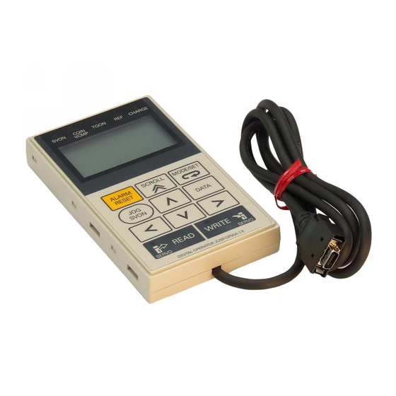
1.1 Digital Operator Types and Connections Digital Operator Types and Connections A Digital Operator is used to display and set parameters in a SERVO- PACK. You can use the following two types of Digital Operators with Σ-7-Series SERVOPACKs. • Digital Operator for Σ-V-Series and Σ-7-Series SERVOPACKs: JUSP- OP05A-1-E •... - Page 42 Series SERVOPACKs: JUSP-OP05A-1-E To use the Digital Operator for Σ-V-Series and Σ-7-Series SERVOPACKs (JUSP-OP05A-1-E), connect it to the CN3 connector on the SERVO- PACK. COIN TGON CHARGE VCMP YASKAWA CROLL MODE/ ET ALARM RE ET DATA READ WRITE GD7 ERVOPACK...
- Page 43 -7- Series SERVOPACK. To do so, use the JZSP-CVS05-A3-E Digital Operator Converter Cable to connect to the SERVOPACK. Connect to the CN3 connector on the SERVOPACK. SVON C OIN TGON CHARGE VCMP YASKAWA SCROLL MODE/SET ALARM RESET DATA SVON READ...
-
Page 44: Part Names And Functions
1.2 Part Names and Functions Part Names and Functions Indicator (five red LED indicator ) COI N TGON CHARGE VCMP (17 character × 5 line ) YASKAWA CROLL MODE/ ET ALARM RE ET DATA Operation key READ WRITE ERVO ERVO DIGITAL OPERATOR JU P-OP05A-1-E Indicator (red LED ... - Page 45 1.2 Part Names and Functions Operation Keys Description Resets alarms. (An alarm cannot be reset until the cause of the alarm is removed.) Changes the mode of the Digital Operator. • When setting parameters, moves the cursor as follows: From the parameter number area to the setting area From the setting area to the parameter number area •...
-
Page 46: Changing Functions
1.3 Changing Functions Changing Functions When you connect the Digital Operator to the SERVOPACK and turn ON the power supply to the SERVOPACK, the Initial Display will appear and then the Parameter/Monitor Mode Main Menu will be displayed. Press Key to change the mode. Power ON Initial Display Displayed for approx. -
Page 47: Status Indications
1.4 Status Indications Status Indications The status of the SERVOPACK is displayed at the upper left of the display. An abbreviation of the current mode is displayed at the upper right of the display. If you are connected to a Σ-7 ERVOPACK, “1”... -
Page 48: Parameter/Monitor Functions
Parameter/ Monitor Functions This chapter describes operating procedures for the parameter/monitor functions. Parameters ....2-2 2.1.1 Setting Parameters ....2-2 2.1.2 Types of Parameters . -
Page 49: Parameters
2.1 Parameters 2.1.1 Setting Parameters Parameters This section describes how to set parameters in the Parameter/Monitor Mode. There are two types of notations used for parameters, one for parame- ters that require selection of a function and one for parameters that require numeric settings. - Page 50 2.1 Parameters 2.1.1 Setting Parameters Continued from previous page. Step Operation Result The cursor will move from the parameter number to the setting. The first digit on the right in the set- ting will flash. 1 : B B P R M / M O N Press the Key.
- Page 51 2.1 Parameters 2.1.1 Setting Parameters Operation Example 2: Setting a Parameter That Requires a Numeric Setting The following example shows how to set Pn304 (Jogging Speed) to 1,000 min Step Operation Result P R M / M O N 1 : B B U n 0 0 0 = 0 0 0 0 0 Press the...
- Page 52 2.1 Parameters 2.1.1 Setting Parameters Continued from previous page. Step Operation Result 1 : B B P R M / M O N 0 4 = 0 0 5 0 0 Press the Key twice to move U n 0 0 2 = 0 0 0 0 0 the cursor to the hundreds digit of U n 0 0 8 =...
-
Page 53: Types Of Parameters
2.1 Parameters 2.1.2 Types of Parameters 2.1.2 Types of Parameters There are the following two types of SERVOPACK parameters. Classification Meaning Parameters for the basic settings that are Setup Parameters required for operation. Parameters that are used to adjust servo per- Tuning Parameters formance. -
Page 54: Monitors
2.2 Monitors 2.2.1 Monitor Items Monitors This section describes how to display and operate monitors in the Parameter/Monitor Mode. 2.2.1 Monitor Items Un No. Content of Display Unit Un000 Motor Speed Un001 Speed Reference Torque Reference (percentage of rated Un002 torque) Rotary Servomotors: Rotational Angle 1... - Page 55 2.2 Monitors 2.2.1 Monitor Items Continued from previous page. Un No. Content of Display Unit Power Consumed by DB Resistance (percentage of processable power at DB Un00B activation: displayed in cycles of 10 sec- onds) Un00C Input Reference Pulse Counter Reference units Un00D Feedback Pulse Counter...
- Page 56 2.2 Monitors 2.2.1 Monitor Items Continued from previous page. Un No. Content of Display Unit Position within One Rotation of Absolute Un041 Encoder pulses Encoder Un042 Lower Bits of Absolute Encoder Position Encoder pulses Un043 Upper Bits of Absolute Encoder Position Encoder pulses Un084 Linear Encoder Pitch Un085...
-
Page 57: Interpreting The Monitor Displays
2.2 Monitors 2.2.2 Interpreting the Monitor Displays 2.2.2 Interpreting the Monitor Displays Input Signal Monitor The input signal monitor (Un005) is displayed as shown below. The top indicates OFF (high level) and the bottom indicates ON (low level). Undefined digits are always shown as being ON. U n 0 0 5 = 8 7 6 5 4 2 1 Digit... - Page 58 2.2 Monitors 2.2.2 Interpreting the Monitor Displays Σ-7W MECHATROLINK-III Communications Reference SERVOPACKs When Axis 1 Is Displayed Display Digit Input Pin Signal Name* Number Number (You can change the allocations.) CN1-3 P-OT (Forward Drive Prohibit) signal CN1-4 N-OT (Reverse Drive Prohibit) signal CN1-5 /DEC (Origin Return Deceleration Switch) signal CN1-6...
- Page 59 2.2 Monitors 2.2.2 Interpreting the Monitor Displays Output Signal Monitor The output signal monitor (Un006) is displayed as shown below. The top indicates OFF (high level) and the bottom indicates ON (low level). Unde- fined digits are always shown as being ON. U n 0 0 6 = 8 7 6 5 4 2 1 Digit...
- Page 60 2.2 Monitors 2.2.2 Interpreting the Monitor Displays Σ-7W MECHATROLINK-III Communications Reference SERVOPACKs Display Digit Input Pin Signal Name Number Number (You can change the allocations.) CN1-19 and ALM (Servo Alarm) signal for axis 1 CN1-20 CN1-21 and ALM (Servo Alarm) signal for axis 2 CN1-22 CN1-23 and /BK (Brake) signal for axis 1...
-
Page 61: Monitor Display Operations
2.2 Monitors 2.2.3 Monitor Display Operations 2.2.3 Monitor Display Operations To describe monitor display operations, the following example shows how to display Un000 (Motor Speed) on line 1, Un002 (Torque Refer- ence) on line 2, Un005 (Input Signal Monitor) on line 3, and Un006 (Out- put Signal Monitor) on line 4, and then how to save the display status. -
Page 62: 2.2.3 Monitor Display Operations
2.2 Monitors 2.2.3 Monitor Display Operations Continued from previous page. Step Operation Result P R M / M O N 1 : B B U n 0 0 0 = 0 0 0 0 0 U n 0 0 2 = 0 0 0 0 0 Use the Key or... - Page 63 Utility Functions This chapter provides an outline of the utility functions and describes the operating proce- dures for them. Introduction ....3-4 3.1.1 Utility Functions ....3-4 Operating Procedures for Utility Functions .
- Page 64 3.2.14 Manually Adjust Motor Current Detection Signal Offset (Fn00F) ..3-35 3.2.15 Write Prohibition Setting (Fn010) . . . 3-38 3.2.16 Display Servomotor Model (Fn011) ..... . 3-41 3.2.17 Display Software Version (Fn012) .
- Page 65 3.2.40 Absolute Encoder Origin Setting (FnB09) ..... 3-125 3.2.41 INDEXER Status Monitor (FnB0A) ..... 3-127 3.2.42 INDEXER Parameter Setting Initialization (FnB0B) .
-
Page 66: 3.1.1 Utility Functions
3.1 Introduction 3.1.1 Utility Functions Introduction In Utility Mode, Fn numbers are displayed and you can execute the utility functions to operate and adjust the SERVOPACK. The following table lists the utility functions. 3.1.1 Utility Functions Fn No. Name Description Remarks Displays a history of up to the last 10 Fn000 Display Alarm History... - Page 67 3.1 Introduction 3.1.1 Utility Functions Continued from previous page. Fn No. Name Description Remarks Displays the software version of the Fn012 Display Software Version – – SERVOPACK. Multiturn Limit Setting after Resets an A.CC0 alarm that occurred Fn013 Multiturn Limit Disagree- when the multiturn limit was changed –...
- Page 68 3.1 Introduction 3.1.1 Utility Functions Continued from previous page. Fn No. Name Description Remarks Suppresses low and transient vibration Fn205 Vibration Suppression (oscillation) of approximately 1 Hz to – 100 Hz. Slightly rotates the SERVOPACK sev- eral times for a certain period to cause Fn206 Easy FFT the machine to vibrate, detects the res- Wrt OFF...
-
Page 69: Operating Procedures For Utility Functions
3.2 Operating Procedures for Utility Functions Operating Procedures for Utility Functions This section provides the operating procedures for the Utility Mode exe- cution displays that you can select from the Utility Mode Main Menu. The Utility Mode Main Menu is displayed when you press the in Parameter/Monitor Mode. -
Page 70: Display Alarm History (Fn000)
3.2 Operating Procedures for Utility Functions 3.2.1 Display Alarm History (Fn000) 3.2.1 Display Alarm History (Fn000) You can use this utility function to display a history of up to the last 10 alarms. You can check the alarm numbers and time stamps of the alarms that have occurred. - Page 71 3.2 Operating Procedures for Utility Functions 3.2.1 Display Alarm History (Fn000) Operating Procedure Step Operation Result F U N C T I O N 1 : B B Press the Key to display the F n 2 0 7 : V - M o n i t o r Utility Mode Main Menu, and then F n 0 0 0 : A l m H i t o r y...
-
Page 72: Jog (Fn002)
3.2 Operating Procedures for Utility Functions 3.2.2 Jog (Fn002) 3.2.2 Jog (Fn002) You can use this utility function to operate the motor in the forward or reverse direction with the keys on the Digital Operator. For safety, do not jog the motor while the motor is connected to the load (i.e., do not couple the axis to the machine). - Page 73 3.2 Operating Procedures for Utility Functions 3.2.2 Jog (Fn002) Operating Procedure The following procedure shows how to jog the motor at a jogging speed of 1,000 min . (The default setting is 500 min Step Operation Result 1 : B B F U N C T I O N Press the Key to display the...
- Page 74 3.2 Operating Procedures for Utility Functions 3.2.2 Jog (Fn002) Continued from previous page. Step Operation Result The status display will change to RUN and the motor will change to the servo ON state. 1 : R U N J O G Press the Key.
-
Page 75: Origin Search (Fn003)
3.2 Operating Procedures for Utility Functions 3.2.3 Origin Search (Fn003) 3.2.3 Origin Search (Fn003) You can use this utility function to operate the motor with the keys on the Digital Operator, move the motor to the origin within one rotation, and clamp the motor there. - Page 76 3.2 Operating Procedures for Utility Functions 3.2.3 Origin Search (Fn003) Continued from previous page. Step Operation Result The status display will change to 1:RUN and the motor will change to the servo ON state. Note: If the Servomotor is already at the origin, Complete will be displayed.
-
Page 77: Jog Program (Fn004)
3.2 Operating Procedures for Utility Functions 3.2.4 Jog Program (Fn004) 3.2.4 Jog Program (Fn004) You can use this utility function to perform continuous operation with a preset operation pattern, travel distance, movement speed, accelera- tion/deceleration time, waiting time, and number of movements. Preparations Always check the following before you execute program jogging. - Page 78 3.2 Operating Procedures for Utility Functions 3.2.4 Jog Program (Fn004) Operating Procedure Step Operation Result F U N C T I O N 1 : B B Press the Key to display the F n 0 0 : Z - e a r c h Utility Mode Main Menu, and then F n 0 0 4 : P r o g r a m J O G...
- Page 79 3.2 Operating Procedures for Utility Functions 3.2.4 Jog Program (Fn004) Continued from previous page. Step Operation Result Operation will start after the waiting time that is set in Pn535. 1 : R U N P R G J O G P n 5 1 = 0 0 0 2 7 6 8...
-
Page 80: Initialize Parameters (Fn005)
3.2 Operating Procedures for Utility Functions 3.2.5 Initialize Parameters (Fn005) 3.2.5 Initialize Parameters (Fn005) You can use this utility function to initialize the parameters to the default settings. Preparations Always check the following before you initialize the parameter settings. • The parameters must not be write-prohibited (Fn010 must be set to 0000). - Page 81 3.2 Operating Procedures for Utility Functions 3.2.5 Initialize Parameters (Fn005) Continued from previous page. Step Operation Result The parameters will be initialized. Parameter Init will flash on the dis- play while the parameters are being initialized. It will stop flashing when processing has been completed and the follow- ing status displays will appear.
-
Page 82: Clear Alarm History (Fn006)
3.2 Operating Procedures for Utility Functions 3.2.6 Clear Alarm History (Fn006) 3.2.6 Clear Alarm History (Fn006) You can use this utility function to clear the alarm history. This utility function is the only way to clear the alarm history. The alarm history is not cleared when you reset alarms or turn OFF the power sup- ply to the SERVOPACK. -
Page 83: Reset Absolute Encoder (Fn008)
3.2 Operating Procedures for Utility Functions 3.2.7 Reset Absolute Encoder (Fn008) 3.2.7 Reset Absolute Encoder (Fn008) You must reset (initialize) the absolute encoder at the following times. • When starting the system for the first time • When an A.810 alarm (Encoder Backup Alarm) occurs •... - Page 84 3.2 Operating Procedures for Utility Functions 3.2.7 Reset Absolute Encoder (Fn008) Operating Procedure Step Operation Result 1 : A . 8 1 0 F U N C T I O N Press the Key to display the F n 0 0 6 : A l m H i t C l r Utility Mode Main Menu, and then F n 0 0 8 : M t u r n C l r...
-
Page 85: Autotune Analog (Speed/Torque) Reference Offset (Fn009)
3.2 Operating Procedures for Utility Functions 3.2.8 Autotune Analog (Speed/Torque) Reference Offset (Fn009) 3.2.8 Autotune Analog (Speed/Torque) Refer- ence Offset (Fn009) You can use this utility function to measure the offset to automatically adjust the reference voltage. The measured offset is saved in the SERVOPACK. 1. - Page 86 3.2 Operating Procedures for Utility Functions 3.2.8 Autotune Analog (Speed/Torque) Reference Offset (Fn009) Operating Procedure Step Operation Result Turn OFF the servo. – Input a reference voltage of 0 V. – F U N C T I O N 1 : B B Press the Key to display the F n 0 0 8 : M t u r n C l r...
-
Page 87: Manually Adjust Speed Reference Offset (Fn00A)
3.2 Operating Procedures for Utility Functions 3.2.9 Manually Adjust Speed Reference Offset (Fn00A) 3.2.9 Manually Adjust Speed Reference Off- set (Fn00A) You can use this utility function to directly input an offset to adjust the speed reference. The offset is adjusted manually in the following cases. •... - Page 88 3.2 Operating Procedures for Utility Functions 3.2.9 Manually Adjust Speed Reference Offset (Fn00A) Operating Procedure Step Operation Result Input a reference voltage of 0 V. – F U N C T I O N 1 : B B Press the Key to display the F n 0 0 9 : R e f A d j Utility Mode Main Menu, and then...
-
Page 89: Manually Adjust Torque Reference Offset (Fn00B)
3.2 Operating Procedures for Utility Functions 3.2.10 Manually Adjust Torque Reference Offset (Fn00B) 3.2.10 Manually Adjust Torque Reference Offset (Fn00B) You can use this utility function to directly input an offset to adjust the torque reference. The offset is adjusted manually in the following cases. •... - Page 90 3.2 Operating Procedures for Utility Functions 3.2.10 Manually Adjust Torque Reference Offset (Fn00B) Operating Procedure Step Operation Result Input a reference voltage of 0 V. – F U N C T I O N 1 : B B Press the Key to display the F n 0 0 A : V e l A d j Utility Mode Main Menu, and then...
-
Page 91: Adjust Analog Monitor Output Offset (Fn00C)
3.2 Operating Procedures for Utility Functions 3.2.11 Adjust Analog Monitor Output Offset (Fn00C) 3.2.11 Adjust Analog Monitor Output Offset (Fn00C) You can use this utility function to manually adjust the analog monitor output offsets for the torque reference monitor and motor speed moni- tor. - Page 92 3.2 Operating Procedures for Utility Functions 3.2.11 Adjust Analog Monitor Output Offset (Fn00C) Continued from previous page. Step Operation Result Adjust the offset for channel 1 (the torque reference monitor). 1 : B B Z e r o A D J C H 1 = - 0 0 0 0 5 Press the Key or...
-
Page 93: Adjust Analog Monitor Output Gain (Fn00D)
3.2 Operating Procedures for Utility Functions 3.2.12 Adjust Analog Monitor Output Gain (Fn00D) 3.2.12 Adjust Analog Monitor Output Gain (Fn00D) You can use this utility function to manually adjust the analog monitor output gains for the torque reference monitor and motor speed monitor. You can adjust the torque reference monitor and motor speed monitor gains individually. - Page 94 3.2 Operating Procedures for Utility Functions 3.2.12 Adjust Analog Monitor Output Gain (Fn00D) Continued from previous page. Step Operation Result 1 : B B G a i n A D J Adjust the gain for channel 1 (the C H 1 = 0 0 1 2 5 torque reference monitor).
-
Page 95: Autotune Motor Current Detection Signal Offset
3.2 Operating Procedures for Utility Functions 3.2.13 Autotune Motor Current Detection Signal Offset (Fn00E) 3.2.13 Autotune Motor Current Detection Signal Offset (Fn00E) The adjustment that is made by this utility function is completed at the factory. There is normally no reason to execute it. Execute this utility function if you think the torque ripple is abnormally large due to the current detection signal offset. - Page 96 3.2 Operating Procedures for Utility Functions 3.2.13 Autotune Motor Current Detection Signal Offset (Fn00E) Operating Procedure Step Operation Result F U N C T I O N 1 : B B Press the Key to display the F n 0 0 D : M o n G a i n A d j Utility Mode Main Menu, and then F n 0 0 E : C u r A u t o A d j use the...
-
Page 97: Manually Adjust Motor Current Detection Signal Offset (Fn00F)
3.2 Operating Procedures for Utility Functions 3.2.14 Manually Adjust Motor Current Detection Signal Offset (Fn00F) 3.2.14 Manually Adjust Motor Current Detection Signal Offset (Fn00F) The adjustment that is made by this utility function is completed at the factory. There is normally no reason to execute it. Execute this utility function in the following cases. - Page 98 3.2 Operating Procedures for Utility Functions 3.2.14 Manually Adjust Motor Current Detection Signal Offset (Fn00F) Operating Procedure Step Operation Result F U N C T I O N 1 : B B Press the Key to display the F n 0 0 F : C u r M a n u A d j Utility Mode Main Menu, and then F n 0 1 0 : P r m P r o t e c t use the...
- Page 99 3.2 Operating Procedures for Utility Functions 3.2.14 Manually Adjust Motor Current Detection Signal Offset (Fn00F) Continued from previous page. Step Operation Result 1 : R U N Adjust the offset for phase V. M a n u a l O f f e t - A D J Use the Key or...
-
Page 100: Fn00E
3.2 Operating Procedures for Utility Functions 3.2.15 Write Prohibition Setting (Fn010) 3.2.15 Write Prohibition Setting (Fn010) You can use this utility function to restrict executing the utility functions to prevent careless changes to the parameter settings. When you prohibit writing, writing parameters and executing utility func- tions are restricted as described below. - Page 101 3.2 Operating Procedures for Utility Functions 3.2.15 Write Prohibition Setting (Fn010) Continued from previous page. When Writing Is Pro- Fn No. Function hibited Fn01B Initialize Vibration Detection Level Cannot be executed. Fn01E Display SERVOPACK and Servomotor IDs Can be executed. Display Servomotor ID from Feedback Option Fn01F Can be executed.
- Page 102 3.2 Operating Procedures for Utility Functions 3.2.15 Write Prohibition Setting (Fn010) Operating Procedure Step Operation Result 1 : B B F U N C T I O N Press the Key to display the F n 0 0 F : C u r M a n u A d j Utility Mode Main Menu, and then F n 0 1 0 : P r m P r o t e c t use the...
-
Page 103: Display Servomotor Model (Fn011)
3.2 Operating Procedures for Utility Functions 3.2.16 Display Servomotor Model (Fn011) 3.2.16 Display Servomotor Model (Fn011) You can use this utility function to display the model, voltage, capacity, encoder type, and encoder resolution of the Servomotor that is con- nected to the SERVOPACK. If the SERVOPACK has custom specifica- tions, the specifications number is also displayed. - Page 104 3.2 Operating Procedures for Utility Functions 3.2.16 Display Servomotor Model (Fn011) Continued from previous page. Step Operation Result The Fn011 (Display Servomotor Model) execution display will appear. The motor and encoder information will be displayed. ervomotor Model Type GM7A GM7P GM7G GM7M GM7D...
- Page 105 3.2 Operating Procedures for Utility Functions 3.2.16 Display Servomotor Model (Fn011) * The displayed information is as follows for a Linear Servomotor: ervomotor Model Type Linear ervomotor 1 : B B M t l n f o ervomotor input voltage T Y P E 4 0 A C 2 0 0 V 4 0 0 W ervomotor capacity...
-
Page 106: Display Software Version (Fn012)
3.2 Operating Procedures for Utility Functions 3.2.17 Display Software Version (Fn012) 3.2.17 Display Software Version (Fn012) You can use this utility function to display the software version of the SERVOPACK and the software version of the connected encoder. Preparations No preparations are required. Operating Procedure Step Operation... -
Page 107: Multiturn Limit Setting After Multiturn Limit Disagreement Alarm (Fn013)
3.2 Operating Procedures for Utility Functions 3.2.18 Multiturn Limit Setting after Multiturn Limit Disagreement Alarm (Fn013) 3.2.18 Multiturn Limit Setting after Multiturn Limit Disagreement Alarm (Fn013) If you change the value of the multiturn limit (Pn205) when an absolute encoder is being used, an A.CC0 alarm (Multiturn Limit Disagreement) will be output. - Page 108 3.2 Operating Procedures for Utility Functions 3.2.18 Multiturn Limit Setting after Multiturn Limit Disagreement Alarm (Fn013) Operating Procedure Step Operation Result 1 : A . C C 0 F U N C T I O N Press the Key to display the F n 0 1 2 : o f t V e r Utility Mode Main Menu, and then...
-
Page 109: Reset Option Module Configuration Error (Fn014)
3.2 Operating Procedures for Utility Functions 3.2.19 Reset Option Module Configuration Error (Fn014) 3.2.19 Reset Option Module Configuration Error (Fn014) If Option Modules are attached to the SERVOPACK, the SERVOPACK detects the presence and models of the connected Option Models. If it finds any errors, it outputs alarms. - Page 110 3.2 Operating Procedures for Utility Functions 3.2.19 Reset Option Module Configuration Error (Fn014) Operating Procedure Step Operation Result F U N C T I O N 1 : B B Press the Key to display the F n 0 1 : M t u r n L m Utility Mode Main Menu, and then F n 0 1 4 : O p t I n i t...
-
Page 111: Initialize Vibration Detection Level (Fn01B)
3.2 Operating Procedures for Utility Functions 3.2.20 Initialize Vibration Detection Level (Fn01B) 3.2.20 Initialize Vibration Detection Level (Fn01B) You can detect machine vibration during operation to automatically adjust the settings of Pn312 or Pn384 (Vibration Detection Level) to detect A.520 alarms (Vibration Alarm) and A.911 warnings (Vibration Warning) more precisely. - Page 112 3.2 Operating Procedures for Utility Functions 3.2.20 Initialize Vibration Detection Level (Fn01B) Operating Procedure Step Operation Result F U N C T I O N 1 : R U N Press the Key to display the F n 0 1 4 : O p t I n i t Utility Mode Main Menu, and then F n 0 1 B : V i b l v l I n i t use the...
- Page 113 3.2 Operating Procedures for Utility Functions 3.2.20 Initialize Vibration Detection Level (Fn01B) Continued from previous page. Step Operation Result The display will return to the Utility Mode Main Menu. F U N C T I O N 1 : R U N F n 0 1 4 : O p t I n i t Press the Key.
-
Page 114: Display Servopack And Servomotor Ids (Fn01E)
3.2 Operating Procedures for Utility Functions 3.2.21 Display SERVOPACK and Servomotor IDs (Fn01E) 3.2.21 Display SERVOPACK and Servomotor IDs (Fn01E) You can use this utility function to display ID information on the SERVO- PACK and on the Servomotor, encoder, and Option Module that are connected to it. - Page 115 3.2 Operating Procedures for Utility Functions 3.2.21 Display SERVOPACK and Servomotor IDs (Fn01E) Preparations No preparations are required. Operating Procedure Step Operation Result F U N C T I O N 1 : R U N Press the Key to display the F n 0 1 B : V i b l v l I n i t Utility Mode Main Menu, and then F n 0 1 E :...
- Page 116 3.2 Operating Procedures for Utility Functions 3.2.21 Display SERVOPACK and Servomotor IDs (Fn01E) Continued from previous page. Step Operation Result The encoder information will be dis- played. erial number Model 1 : B B v M t O p I D E n c o d e r U T T A I - B 2 4 R H Press the...
-
Page 117: Display Servomotor Id From Feedback Option Module (Fn01F)
3.2 Operating Procedures for Utility Functions 3.2.22 Display Servomotor ID from Feedback Option Module (Fn01F) 3.2.22 Display Servomotor ID from Feedback Option Module (Fn01F) You can use this utility function to display the Servomotor and encoder ID information from the Feedback Option Module connected to the SER- VOPACK. - Page 118 3.2 Operating Procedures for Utility Functions 3.2.22 Display Servomotor ID from Feedback Option Module (Fn01F) Preparations No preparations are required. Operating Procedure Step Operation Result 1 : B B F U N C T I O N Press the Key, and then use F n 0 1 E : v M o t O p I D F n 0 1 F : F B O p M o t I D...
- Page 119 3.2 Operating Procedures for Utility Functions 3.2.22 Display Servomotor ID from Feedback Option Module (Fn01F) Continued from previous page. Step Operation Result The parameter file ID information will be displayed. Parameter file ver ion 1 : B B F B O p M t I D Press the Key.
-
Page 120: Set Origin (Fn020)
3.2 Operating Procedures for Utility Functions 3.2.23 Set Origin (Fn020) 3.2.23 Set Origin (Fn020) You can use this utility function to set the current position of the external absolute encoder as the origin when you are using a Linear Servomotor or when you are using an external absolute encoder for fully-closed loop control. - Page 121 3.2 Operating Procedures for Utility Functions 3.2.23 Set Origin (Fn020) Operating Procedure Step Operation Result 1 : B B F U N C T I O N Press the Key to display the F n 0 1 F : F B O p M o t I D Utility Mode Main Menu, and then F n 0 2 0 : - O r i g...
-
Page 122: Reset Motor Type Change Detected Status
3.2 Operating Procedures for Utility Functions 3.2.24 Reset Motor Type Change Detected Status (Fn021) 3.2.24 Reset Motor Type Change Detected Sta- tus (Fn021) After an A.070 (Motor Type Change Detected) alarm occurs, you must reset the Motor Type Change Detected status. Preparations Always check the following before you reset the Motor Type Change Detected. -
Page 123: Software Reset (Fn030)
3.2 Operating Procedures for Utility Functions 3.2.25 Software Reset (Fn030) 3.2.25 Software Reset (Fn030) You can use this utility function to internally perform a software reset of the SERVOPACK. This utility function is used when resetting alarms and changing the settings of parameters that normally require turning the power supply to the SERVOPACK OFF and ON again. - Page 124 3.2 Operating Procedures for Utility Functions 3.2.25 Software Reset (Fn030) Operating Procedure Step Operation Result 1 : B B F U N C T I O N Press the Key to display the F n 0 2 0 : - O r i g Utility Mode Main Menu, and then F n 0 o f t R e e t...
- Page 125 3.2 Operating Procedures for Utility Functions 3.2.25 Software Reset (Fn030) Continued from previous page. Step Operation Result The display will return to the Utility Mode Main Menu. 1 : B B F U N C T I O N F n 0 2 0 : - O r i g Press the Key.
-
Page 126: Polarity Detection (Fn080)
3.2 Operating Procedures for Utility Functions 3.2.26 Polarity Detection (Fn080) 3.2.26 Polarity Detection (Fn080) You can use this utility function to detect the polarity and store motor phase information in the SERVOPACK. Executing this utility function eliminates the need to detect the polarity every time you turn ON the power supply so that you can start operation immediately. - Page 127 3.2 Operating Procedures for Utility Functions 3.2.26 Polarity Detection (Fn080) Operating Procedure Step Operation Result 1 : B B F U N C T I O N Press the Key to display the F n 0 o f t R e e t Utility Mode Main Menu, and then F n 0 8 0 : P o l e D e t e c t use the...
- Page 128 3.2 Operating Procedures for Utility Functions 3.2.26 Polarity Detection (Fn080) Continued from previous page. Step Operation Result The display will return to the Utility Mode Main Menu. 1 : B B F U N C T I O N F n 0 o f t R e e t Press the Key.
-
Page 129: Tuning-Less Level Setting (Fn200)
3.2 Operating Procedures for Utility Functions 3.2.27 Tuning-less Level Setting (Fn200) 3.2.27 Tuning-less Level Setting (Fn200) You can use this utility function to set the tuning-less rigidity and load levels. Preparations Always check the following before you set the tuning-less rigidity and load levels. - Page 130 3.2 Operating Procedures for Utility Functions 3.2.27 Tuning-less Level Setting (Fn200) Operating Procedure Step Operation Result Press the Key to display the 1 : R U N F U N C T I O N F n 0 8 0 : P o l e D e t e c t Utility Mode Main Menu, and then F n 2 0 0 : T u n e L v l F n 2 0 1 : A A T...
- Page 131 3.2 Operating Procedures for Utility Functions 3.2.27 Tuning-less Level Setting (Fn200) Continued from previous page. Step Operation Result Press the Key or the Key to select the rigidity level. Set the rigidity level to a value between 0 and 7. The larger the value, the higher the gain and the better the response will be.
-
Page 132: Advanced Autotuning Without Reference (Fn201)
3.2 Operating Procedures for Utility Functions 3.2.28 Advanced Autotuning without Reference (Fn201) 3.2.28 Advanced Autotuning without Refer- ence (Fn201) You can use this utility function to perform automatic round-trip opera- tion within a set range. During the operation, the SERVOPACK will be tuned automatically according to machine characteristics. - Page 133 3.2 Operating Procedures for Utility Functions 3.2.28 Advanced Autotuning without Reference (Fn201) • If you start advanced autotuning while the SERVOPACK is in Information speed control, the SERVOPACK will change to position con- trol automatically to perform advanced autotuning. The SER- VOPACK will return to speed control after completing the adjustment.
- Page 134 3.2 Operating Procedures for Utility Functions 3.2.28 Advanced Autotuning without Reference (Fn201) Operating Procedure Step Operation Result 1 : B B F U N C T I O N Press the Key to display the F n 2 0 0 : T u n e L v l Utility Mode Main Menu, and then F n 2 0 1 : A A T F n 2 0 2 : R e f - A A T...
- Page 135 3.2 Operating Procedures for Utility Functions 3.2.28 Advanced Autotuning without Reference (Fn201) Continued from previous page. Step Operation Result Type Select the type according to the machine element to drive. If there is noise or if the gain does not increase, better results may be obtained by changing the rigidity type.
- Page 136 3.2 Operating Procedures for Utility Functions 3.2.28 Advanced Autotuning without Reference (Fn201) Continued from previous page. Step Operation Result Calculation of the moment of inertia will start. While the moment of inertia is being calculated, the setting of Pn103 will flash and 1:ADJ will flash instead of 1:RUN.
- Page 137 3.2 Operating Procedures for Utility Functions 3.2.28 Advanced Autotuning without Reference (Fn201) Continued from previous page. Step Operation Result The calculated moment of inertia Press the Key. will be saved in the SERVOPACK. Note: To end the operation by calculat- DONE will flash on the display for ing only the moment of inertia ratio without adjusting the gains, press...
- Page 138 3.2 Operating Procedures for Utility Functions 3.2.28 Advanced Autotuning without Reference (Fn201) Troubleshooting Problems in the Operation This section provides information on troubleshooting problems that can occur in the operation. NO-OP Flashes on the Display Probable Cause Corrective Action The main circuit power supply is OFF.
- Page 139 3.2 Operating Procedures for Utility Functions 3.2.28 Advanced Autotuning without Reference (Fn201) Continued from previous page. Error Probable Cause Corrective Action The /COIN signal did not turn ON Increase the setting of The positioning completed within approxi- Pn522. If proportional con- width is too narrow or pro- mately 10 seconds trol is set, turn OFF the /P-...
- Page 140 3.2 Operating Procedures for Utility Functions 3.2.28 Advanced Autotuning without Reference (Fn201) Errors during Calculation of Moment of Inertia The following table gives the probable causes of errors that may occur during calculation of the moment of inertia (Jcalc = ON), along with cor- rective actions for the errors.
-
Page 141: Advanced Autotuning With Reference (Fn202)
3.2 Operating Procedures for Utility Functions 3.2.29 Advanced Autotuning with Reference (Fn202) 3.2.29 Advanced Autotuning with Reference (Fn202) You can use this utility function to automatically achieve optimum tuning of the SERVOPACK in response to operation references (pulse train ref- erences) from the host controller. - Page 142 3.2 Operating Procedures for Utility Functions 3.2.29 Advanced Autotuning with Reference (Fn202) Operating Procedure Step Operation Result 1 : B B F U N C T I O N Press the Key to display the F n 2 0 1 : A A T Utility Mode Main Menu, and then F n 2 0 2 : R e f - A A T F n 2 0...
- Page 143 3.2 Operating Procedures for Utility Functions 3.2.29 Advanced Autotuning with Reference (Fn202) Continued from previous page. Step Operation Result The execution display for advanced autotuning with a reference input will appear. 1 : B B A A T P n 1 0 = 0 0 0 0 0 P n 1 0 0 = 0 0 4 0 .
- Page 144 3.2 Operating Procedures for Utility Functions 3.2.29 Advanced Autotuning with Reference (Fn202) Continued from previous page. Step Operation Result The adjusted settings will be saved in the SERVOPACK. The status dis- play will flash DONE as shown below for approximately one sec- Press the Key.
- Page 145 3.2 Operating Procedures for Utility Functions 3.2.29 Advanced Autotuning with Reference (Fn202) Troubleshooting Problems in the Operation This section provides information on troubleshooting problems that can occur in the operation. NO-OP Flashes on the Display Probable Cause Corrective Action The main circuit power supply is OFF.
-
Page 146: One-Parameter Tuning (Fn203)
3.2 Operating Procedures for Utility Functions 3.2.30 One-Parameter Tuning (Fn203) 3.2.30 One-Parameter Tuning (Fn203) You can use this utility function to manually adjust the servo during oper- ation using a speed or position reference input from the host controller. This utility function allows you to automatically set related servo gain settings to balanced conditions by tuning the SERVOPACK with one or two tuning levels. - Page 147 3.2 Operating Procedures for Utility Functions 3.2.30 One-Parameter Tuning (Fn203) Operating Procedure Speed Control Mode Step Operation Result 1 : R U N F U N C T I O N Press the Key to display the F n 2 0 2 : R e f - A A T Utility Mode Main Menu, and then F n 2 0 : O n e P r m T u n...
- Page 148 3.2 Operating Procedures for Utility Functions 3.2.30 One-Parameter Tuning (Fn203) Continued from previous page. Step Operation Result Tuning Mode Set the tuning mode. Select tuning mode 0 or 1. 0: Tunes while giving priority to stability. 1: Tunes while giving priority to response. ...
- Page 149 3.2 Operating Procedures for Utility Functions 3.2.30 One-Parameter Tuning (Fn203) Continued from previous page. Step Operation Result 1 : R U N O n e P r m T u n L E V E L = 0 0 5 0 N F 1 N F 2 A R E...
- Page 150 3.2 Operating Procedures for Utility Functions 3.2.30 One-Parameter Tuning (Fn203) Position Control Mode Step Operation Result 1 : R U N F U N C T I O N Press the Key to display the F n 2 0 2 : R e f - A A T Utility Mode Main Menu, and then F n 2 0 : O n e P r m T u n...
- Page 151 3.2 Operating Procedures for Utility Functions 3.2.30 One-Parameter Tuning (Fn203) Continued from previous page. Step Operation Result Tuning Mode Set the tuning mode. Select tuning mode 2 or 3. 0: Tunes while giving priority to stability. 1: Tunes while giving priority to response. 2: Tunes the SERVOPACK for positioning.
- Page 152 3.2 Operating Procedures for Utility Functions 3.2.30 One-Parameter Tuning (Fn203) Continued from previous page. Step Operation Result If readjustment is required, input a reference from the host controller, select the digit with the Key, change the FF level and FB level with the Key or Key, and check the response.
- Page 153 3.2 Operating Procedures for Utility Functions 3.2.30 One-Parameter Tuning (Fn203) Continued from previous page. Step Operation Result The adjusted settings will be saved Press the Key. in the SERVOPACK and DONE will Note: 1. Press the Key to cancel be displayed. saving the data.
-
Page 154: Adjust Anti-Resonance Control (Fn204)
3.2 Operating Procedures for Utility Functions 3.2.31 Adjust Anti-resonance Control (Fn204) 3.2.31 Adjust Anti-resonance Control (Fn204) You can use this utility function to increase the effectiveness of vibration suppression after one-parameter tuning. This utility function is effective for suppression of continuous vibration frequencies from 100 to 1,000 Hz that occur when the control gain is increased. - Page 155 3.2 Operating Procedures for Utility Functions 3.2.31 Adjust Anti-resonance Control (Fn204) Operating Procedure Adjusting Anti-resonance Control for the First Time Unknown Vibration Frequency Step Operation Result 1 : R U N F U N C T I O N Press the Key to display the F n 2 0...
- Page 156 3.2 Operating Procedures for Utility Functions 3.2.31 Adjust Anti-resonance Control (Fn204) Continued from previous page. Step Operation Result The following display will appear and detection of the vibration fre- quency will start. During detection, freq will flash on the display. Return to step 3 if vibration is not detected.
- Page 157 3.2 Operating Procedures for Utility Functions 3.2.31 Adjust Anti-resonance Control (Fn204) Continued from previous page. Step Operation Result 1 : R U N V i b Use the Key or Key to f r e q = 0 4 0 0 H z d a m p = 0 1 2 0 move the cursor and the Key to set the damping...
- Page 158 3.2 Operating Procedures for Utility Functions 3.2.31 Adjust Anti-resonance Control (Fn204) Known Vibration Frequency Step Operation Result 1 : R U N F U N C T I O N Press the Key to display the F n 2 0 : O n e P r m T u n Utility Mode Main Menu, and then F n 2 0 4 : A - V i b...
- Page 159 3.2 Operating Procedures for Utility Functions 3.2.31 Adjust Anti-resonance Control (Fn204) Continued from previous page. Step Operation Result Use the Key or Key to 1 : R U N V i b move the cursor and the f r e q = 0 1 0 0 H z d a m p = 0 0 0 0 Key to adjust the fre- quency.
- Page 160 3.2 Operating Procedures for Utility Functions 3.2.31 Adjust Anti-resonance Control (Fn204) Continued from previous page. Step Operation Result Use the Key or Key to 1 : R U N V i b move the cursor and the f r e q = 0 4 0 0 H z d a m p = 0 1 2 0 Key to fine-tune the fre- quency.
- Page 161 3.2 Operating Procedures for Utility Functions 3.2.31 Adjust Anti-resonance Control (Fn204) Continued from previous page. Step Operation Result The following display will appear and damp will flash. 1 : R U N V i b Press the Key. f r e q = 0 4 0 0 H z d a m p = 0 1 2 0 Use the Key or...
-
Page 162: Vibration Suppression (Fn205)
3.2 Operating Procedures for Utility Functions 3.2.32 Vibration Suppression (Fn205) 3.2.32 Vibration Suppression (Fn205) You can use this utility function to suppress transitional vibration at a low frequency from 1 to 100 Hz, which is generated mainly when the machine vibrates during positioning. Vibration suppression is set automatically when advanced autotuning or advanced autotuning with a reference input is executed. - Page 163 3.2 Operating Procedures for Utility Functions 3.2.32 Vibration Suppression (Fn205) Operating Procedure Step Operation Result Input an operation reference, repeatedly perform a positioning – operation, and perform steps 2 on. 1 : R U N F U N C T I O N Press the Key to display the F n 2 0 4 : A - V i b...
- Page 164 3.2 Operating Procedures for Utility Functions 3.2.32 Vibration Suppression (Fn205) Continued from previous page. Step Operation Result The value displayed at Measure f will be set as the Setting f value. 1 : R U N V i b M e a u r e f = 0 1 0 . 4 Hz e t t i n g f = 0 1 0 .
- Page 165 3.2 Operating Procedures for Utility Functions 3.2.32 Vibration Suppression (Fn205) Continued from previous page. Step Operation Result The adjusted setting will be saved in the SERVOPACK. The status dis- play will flash DONE as shown Press the Key. below for approximately one sec- ond and then return to RUN.
-
Page 166: Easy Fft (Fn206)
3.2 Operating Procedures for Utility Functions 3.2.33 Easy FFT (Fn206) 3.2.33 Easy FFT (Fn206) You can use this utility function to send a frequency waveform reference from the SERVOPACK to the Servomotor and operate the Servomotor at very low speed several times over a certain period to cause machine vibration. - Page 167 3.2 Operating Procedures for Utility Functions 3.2.33 Easy FFT (Fn206) Operating Procedure Step Operation Result 1 : B B F U N C T I O N Press the Key to display the F n 2 0 5 : V i b Utility Mode Main Menu, and then F n 2 0 6 : E a y F F T...
- Page 168 3.2 Operating Procedures for Utility Functions 3.2.33 Easy FFT (Fn206) Continued from previous page. Step Operation Result The motor will repeatedly perform round-trip operation within 1/4th of a rotation and the SERVOPACK will measure the resonance frequency. During detection, Measure will flash on the display.
- Page 169 3.2 Operating Procedures for Utility Functions 3.2.33 Easy FFT (Fn206) Continued from previous page. Step Operation Result The display will return to Ready. Press the Key. Note: To exit the Easy FFT utility function 1 : R U N y F F T R e a d y at this point, press the Key.
-
Page 170: Program Table Edit/Save (Fnb03)
3.2 Operating Procedures for Utility Functions 3.2.34 Program Table Edit/Save (FnB03) 3.2.34 Program Table Edit/Save (FnB03) This function edits and saves program tables. Saving a program table to flash memory after editing it ensures that the data will be retained even after the control power has been turned off. - Page 171 3.2 Operating Procedures for Utility Functions 3.2.34 Program Table Edit/Save (FnB03) Continued from previous page. Step Operation Result Press the key to view the FnB03 operation screen. Move the cursor using the keys and keys (or the keys) to select the article and program step of the program table to be edited.
- Page 172 3.2 Operating Procedures for Utility Functions 3.2.34 Program Table Edit/Save (FnB03) Method for Moving the Cursor The values within the frames in the figure below are the articles and steps of the program table displayed at the digital operator. PGM TEP RD T R PD...
- Page 173 3.2 Operating Procedures for Utility Functions 3.2.34 Program Table Edit/Save (FnB03) Details on How to Set Table Settings Details on the setting method for step 5 in Editing Program Table on page 3-108 are shown below. If the number of display digits is exceeded when Expansion Mode is enabled (PnB54 = 1), the table name will be abbreviated.
- Page 174 3.2 Operating Procedures for Utility Functions 3.2.34 Program Table Edit/Save (FnB03) DEC: Deceleration Move cursor Change deceleration If the value becomes less than 1, “:” is displayed. POUT: Programmable Output Signals Move cursor Change programmable output signal Pressing the key changes the display in the following order.
- Page 175 3.2 Operating Procedures for Utility Functions 3.2.34 Program Table Edit/Save (FnB03) Saving Program Tables The operating procedure for saving program tables is shown below. Step Operation Result Display the program table editing screen. Press the key to view the pro- gram table save operation screen.
-
Page 176: Zone Table Edit/Save (Fnb04)
3.2 Operating Procedures for Utility Functions 3.2.35 ZONE Table Edit/Save (FnB04) 3.2.35 ZONE Table Edit/Save (FnB04) This function edits and saves ZONE tables. Saving a ZONE table to flash memory after editing it ensures that the data will be retained even after the control power has been turned off. - Page 177 3.2 Operating Procedures for Utility Functions 3.2.35 ZONE Table Edit/Save (FnB04) Continued from previous page. Step Operation Result Move the cursor using the keys and keys to select the ZONE table number to be edited. Refer to the following section for details on the methods to move the cursor.
- Page 178 3.2 Operating Procedures for Utility Functions 3.2.35 ZONE Table Edit/Save (FnB04) Method for Moving the Cursor The values within the frames in the figure below are the ZONE table numbers displayed at the digital operator. ZONE Number ZONE P ZONE N ZONE Number ZONE P...
- Page 179 3.2 Operating Procedures for Utility Functions 3.2.35 ZONE Table Edit/Save (FnB04) Saving ZONE Tables The operating procedure for saving ZONE tables is shown below. Step Operation Result Display the ZONE table editing screen. Press the key to view the ZONE table save screen. Move the cursor with the keys to select “STORE”.
-
Page 180: Jog Speed Table Edit/Save (Fnb05)
3.2 Operating Procedures for Utility Functions 3.2.36 JOG Speed Table Edit/Save (FnB05) 3.2.36 JOG Speed Table Edit/Save (FnB05) This function edits and saves JOG speed tables. Saving a JOG speed table to flash memory after editing it ensures that the data will be retained even after the control power has been turned off. - Page 181 3.2 Operating Procedures for Utility Functions 3.2.36 JOG Speed Table Edit/Save (FnB05) Continued from previous page. Step Operation Result Press the key to move the cur- sor to the setting side of the table. Move the cursor with the keys, and change the JOG speed setting with the keys.* On pressing the...
-
Page 182: Program Table Initialization (Fnb06)
3.2 Operating Procedures for Utility Functions 3.2.37 Program Table Initialization (FnB06) Continued from previous page. Step Operation Result Move the cursor with the keys to select “STORE”. Note: Selecting “CANCEL” and pressing key will return the display to the JOG speed table editing screen. - Page 183 3.2 Operating Procedures for Utility Functions 3.2.37 Program Table Initialization (FnB06) Operating Procedure Step Operation Result Press the key to open the Util- ity Function Mode main menu, and move the cursor with the keys to select FnB06. Press the key to view the FnB06 operation screen.
-
Page 184: Zone Table Initialization (Fnb07)
3.2 Operating Procedures for Utility Functions 3.2.38 ZONE Table Initialization (FnB07) 3.2.38 ZONE Table Initialization (FnB07) This function initializes ZONE tables and restores the settings on ship- ment from the factory. Preparation Always check the following before you initialize a ZONE table. •... -
Page 185: Jog Speed Table Initialization (Fnb08)
3.2 Operating Procedures for Utility Functions 3.2.39 JOG Speed Table Initialization (FnB08) Continued from previous page. Step Operation Result When ZONE table initialization has been completed normally, “Done.” is displayed. Press the key to return to the Utility Function Mode main menu. * If the key is pressed in an operation prohibited state, “Error.”... - Page 186 3.2 Operating Procedures for Utility Functions 3.2.39 JOG Speed Table Initialization (FnB08) Continued from previous page. Step Operation Result Press the key to view the FnB08 operation screen. Press the key to start JOG speed table initialization.* Do not turn off the control power supply until initialization has been completed normally.
-
Page 187: Absolute Encoder Origin Setting (Fnb09)
3.2 Operating Procedures for Utility Functions 3.2.40 Absolute Encoder Origin Setting (FnB09) 3.2.40 Absolute Encoder Origin Setting (FnB09) This utility function replaces the current position with a specified posi- tion. Also updates PnB25 with the absolute position offset value to achieve the position specified by this utility function. - Page 188 3.2 Operating Procedures for Utility Functions 3.2.40 Absolute Encoder Origin Setting (FnB09) Continued from previous page. Step Operation Result Press the key to view the FnB09 operation screen. Move the cursor with the keys, and change the setting for the position whose current position is to be replaced with the keys.
-
Page 189: Indexer Status Monitor (Fnb0A)
3.2 Operating Procedures for Utility Functions 3.2.41 INDEXER Status Monitor (FnB0A) 3.2.41 INDEXER Status Monitor (FnB0A) This function shows the internal status of the INDEXER Module, such as the current position and input/output signals. Preparation None Operating Procedure Step Operation Result Press the key to open the Util-... - Page 190 3.2 Operating Procedures for Utility Functions 3.2.41 INDEXER Status Monitor (FnB0A) Monitor Display Content List Display Display Serial Display Example Units Code Content Command • ALM = A.: A SERVOPACK alarm/warning is in effect ( is the alarm/warn- ing code). •...
- Page 191 3.2 Operating Procedures for Utility Functions 3.2.41 INDEXER Status Monitor (FnB0A) Continued from previous page. Display Display Serial Display Example Units Code Content Command IN2 = 1110 9 8 7 6 5 4 3 2 1 digit Upper level: Photocoupler ON Lower level: Photocoupler OFF Display Digit Signal Name...
- Page 192 3.2 Operating Procedures for Utility Functions 3.2.41 INDEXER Status Monitor (FnB0A) Continued from previous page. Display Display Serial Display Example Units Code Content Command OUT2 = 9 8 7 6 5 4 3 2 1 digit Upper level: Photocoupler ON Lower level: Photocoupler OFF Display Digit Signal Name...
- Page 193 3.2 Operating Procedures for Utility Functions 3.2.41 INDEXER Status Monitor (FnB0A) Continued from previous page. Display Display Serial Display Example Units Code Content Command STS = 7 6 5 4 3 2 1 digit Upper level: ON Lower level: OFF Display Digit Status Flag Number...
-
Page 194: 3.2.42 Indexer Parameter Setting Initialization
3.2 Operating Procedures for Utility Functions 3.2.42 INDEXER Parameter Setting Initialization (FnB0B) Continued from previous page. Display Display Serial Display Example Units Code Content Command Registra- Refer- RPOS tion Target RPOS = +12345678 ence RPOS Position unit Registra- Refer- RDST tion Target RDST = 12345678 ence... - Page 195 3.2 Operating Procedures for Utility Functions 3.2.42 INDEXER Parameter Setting Initialization (FnB0B) • The RES command must not being executed. Operating Procedure Step Operation Result Press the key to open the Util- ity Function Mode main menu, and move the cursor with the keys to select FnB0B.
-
Page 196: Indexer Alarm Reset (Fnb0C)
3.2 Operating Procedures for Utility Functions 3.2.43 INDEXER Alarm Reset (FnB0C) 3.2.43 INDEXER Alarm Reset (FnB0C) This function resets alarms at both the SERVOPACK and INDEXER Module, and clears the alarm history at the INDEXER Module. • INDEXER Module alarms are not reset by the “ALARM RESET” button of the digital operator. -
Page 197: Indexer Alarm History Display (Fnb0D)
3.2 Operating Procedures for Utility Functions 3.2.44 INDEXER Alarm History Display (FnB0D) Continued from previous page. Step Operation Result When Resetting Alarms Use the keys to select “ALM state”. When Clearing the Alarm History Use the keys to select “ALM History”. - Page 198 3.2 Operating Procedures for Utility Functions 3.2.44 INDEXER Alarm History Display (FnB0D) Operating Procedure Step Operation Result Press the key to open the Util- ity Function Mode main menu, and move the cursor with the keys to select FnB0D. Press the key to view the alarm history.
-
Page 199: Parameter Copy Functions
Parameter Copy Functions This chapter describes operating procedures for the parameter copy functions. Introduction ....4-2 4.1.1 Parameter Copy Mode Functions ..4-2 Operating Procedures in Parameter Copy Mode . -
Page 200: Introduction
4.1 Introduction 4.1.1 Parameter Copy Mode Functions Introduction Σ The Digital Operator for -7-Series Servo Systems has a storage area of seven blocks of parameters. One block is used for one SERVOPACK. In Parameter Copy Mode, you can use these parameter blocks. Note: The parameter copy functions are not supported for Σ-7W SERVOPACKs and Σ-7S SERVOPACKs with the MECHATROLINK-4 communications reference. -
Page 201: Operating Procedures In Parameter Copy Mode
4.2 Operating Procedures in Parameter Copy Mode 4.2.1 Reading Parameters from the SERVOPACK (SERVO→OP) Operating Procedures in Parameter Copy Mode This section describes the operating procedures for the functions that you can select from the Main Menu in Parameter Copy Mode. Press the Key to display the Parameter Copy Mode Main Menu. - Page 202 4.2 Operating Procedures in Parameter Copy Mode 4.2.1 Reading Parameters from the SERVOPACK (SERVO→OP) Continued from previous page. Step Operation Result → 1 : B B E R V O Use the Key or Key to * * * * 0 0 : select the parameter block (00 to * * * *...
- Page 203 4.2 Operating Procedures in Parameter Copy Mode 4.2.1 Reading Parameters from the SERVOPACK (SERVO→OP) Continued from previous page. Step Operation Result The display will return to the Param- eter Copy Mode Main Menu. 1 : B B C O P Y →...
-
Page 204: Writing Parameters To The Servopack (Op→Servo)
4.2 Operating Procedures in Parameter Copy Mode 4.2.2 Writing Parameters to the SERVOPACK (OP→SERVO) 4.2.2 Writing Parameters to the SERVOPACK (OP→SERVO) You can use this function to write the parameters that are saved in the selected block in the Digital Operator to a SERVOPACK. Operating Procedure Step Operation... - Page 205 4.2 Operating Procedures in Parameter Copy Mode 4.2.2 Writing Parameters to the SERVOPACK (OP→SERVO) Continued from previous page. Step Operation Result Writing the parameters to the SER- VOPACK will start. → 1 : B B E R V O 0 0 : G D 7 - R 7 0 R e a d i n g...
- Page 206 4.2 Operating Procedures in Parameter Copy Mode 4.2.2 Writing Parameters to the SERVOPACK (OP→SERVO) Continued from previous page. Step Operation Result The display will return to the Param- eter Copy Mode Main Menu. 1 : A . 9 4 1 C O P Y →...
- Page 207 4.2 Operating Procedures in Parameter Copy Mode 4.2.2 Writing Parameters to the SERVOPACK (OP→SERVO) Additional Information on Writing Parame- ters • Do not disconnect the Digital Operator from the SERVOPACK while the parameters are being written. The writing process will be can- celed.
-
Page 208: Verifying Parameters (Verify)
4.2 Operating Procedures in Parameter Copy Mode 4.2.3 Verifying Parameters (VERIFY) 4.2.3 Verifying Parameters (VERIFY) You can use this function to compare the parameters that are saved in the selected block in the Digital Operator with the parameters in the SERVOPACK, and display the results. - Page 209 4.2 Operating Procedures in Parameter Copy Mode 4.2.3 Verifying Parameters (VERIFY) Continued from previous page. Step Operation Result Comparing the parameters will be started. → 1 : B B E R V O 0 0 : G D 7 - R 7 0 R e a d i n g P a r a m e t e r <...
- Page 210 4.2 Operating Procedures in Parameter Copy Mode 4.2.3 Verifying Parameters (VERIFY) Continued from previous page. Step Operation Result The Parameter Block Selection Dis- play will appear. 1 : B B V E R I F Y 0 0 : G D 7 - R 7 0 Press the Key.
- Page 211 4.2 Operating Procedures in Parameter Copy Mode 4.2.3 Verifying Parameters (VERIFY) Additional Information on Verifying Parame- ters • If an empty block (****) is selected to verify parameters, No Data will be displayed and nothing will be compared. (Press the Key to return to the Parameter Block Selection Display.) •...
-
Page 212: Parameter Block List Display (List)
4.2 Operating Procedures in Parameter Copy Mode 4.2.4 Parameter Block List Display (LIST) 4.2.4 Parameter Block List Display (LIST) You can use this function to display the current usage of the seven parameter blocks in the Digital Operator. You can also delete the param- eters for a specified block. - Page 213 4.2 Operating Procedures in Parameter Copy Mode 4.2.4 Parameter Block List Display (LIST) Continued from previous page. Step Operation Result Deleting the parameter block will be started. 1 : B B 0 0 : G D 7 - R 7 0 D e l e t i n g P a r a m e t e r Note: If power is supplied to the motor...
- Page 214 4.2 Operating Procedures in Parameter Copy Mode 4.2.4 Parameter Block List Display (LIST) Additional Information on Deleting Parame- ter Blocks • If an empty block (****) is selected to delete, No Data will be dis- played and nothing will be done. (Press the Key to return to the Parameter Block Selection Display.) •...
-
Page 215: Revision History
Revision History The revision dates and numbers of the revised manuals are given at the bottom of the back cover. MANUAL NO. SIEP S800001 33A <0>-1 Web revision number Revision number Published in Japan November 2015 Date of publication Date of Rev. - Page 216 Phone: +81-4-2962-5151 Fax: +81-4-2962-6138 www.yaskawa.co.jp YASKAWA AMERICA, INC. 2121, Norman Drive South, Waukegan, IL 60085, U.S.A. Phone: +1-800-YASKAWA (927-5292) or +1-847-887-7000 Fax: +1-847-887-7310 www.yaskawa.com YASKAWA ELÉTRICO DO BRASIL LTDA. 777, Avenida Piraporinha, Diadema, São Paulo, 09950-000, Brasil Phone: +55-11-3585-1100 Fax: +55-11-3585-1187 www.yaskawa.com.br...
Need help?
Do you have a question about the E-7 Series and is the answer not in the manual?
Questions and answers