
Related Manuals for Agilent Technologies 4155C


Summary of Contents for Agilent Technologies 4155C
- Page 1 Agilent 4155C Semiconductor Parameter Analyzer Agilent 4156C Precision Semiconductor Parameter Analyzer User’s Guide Agilent Technologies...
- Page 2 Notices © Agilent Technologies 2001 - 2009 Warranty defined in FAR 52.227-19(c)(1-2) (June 1987). U.S. Government users will receive No part of this manual may be reproduced in The material contained in this docu- no greater than Limited Rights as defined in any form or by any means (including elec- ment is provided “as is,”...
- Page 3 This DoC applies to above-listed products placed on the EU market after: March 20, 2010 Date Toshiyuki Kawaji QA Manager Agilent Technologies For further information, please contact your local Agilent Technologies sales office, agent or distributor, or Agilent Technologies Deutschland GmbH, Herrenberger Straße 130, 71034 Böblingen, Germany.
- Page 4 • Herstellerbescheinigung GEÄUSCHEMISSION Lpa < 70 dB am Arbeitsplatz normaler Betrieb nach DIN 45635 T. 19 • Manufacturer’s Declaration ACOUSTIC NOISE EMISSION Lpa < 70dB operator position normal operation per ISO 7779 NOTE This ISM device complies with Canadian ICES-001. Cet appareil ISM est conforme à...
-
Page 5: Safety Summary
In addition, it violates safety standards of design, manufacture, and intended use of the instrument. Agilent Technologies, Inc. assumes no liability for customer’s failure to comply with these requirements. - Page 6 Because of the danger of introducing additional hazards, do not install substitute parts or perform any unauthorized modification to the instrument. Return the instrument to a Agilent Technologies Sales and Service Office for services and repair to ensure that safety features are maintained.
-
Page 7: Safety Symbols
Safety Symbols The general definitions of safety symbols used on equipment or in manuals are listed below. Instruction manual symbol: the product will be marked with this symbol when it is necessary for the user to refer to the instruction manual in order to protect against damage to the instrument. - Page 8 Before touching the connections of the force, guard, and sense terminals, turn the Agilent 4155C/4156C/41501B off and discharge any capacitors whenever possible. If you do not turn the Agilent 4155C/4156C/41501B off, complete “all” of the following items, regardless of any Agilent 4155C/4156C/41501B settings.
- Page 9 高電圧感電注意 4155C/4156C/41501B Agilent のフォース、ガード、センス端子には、危険電圧が出 力されることがあります(HPSMU の場合は最大± 200 Vdc、MPSMU の場合は最大 ± 100 Vdc) 。感電事故防止のため、必ず以下の事柄を守ってください。 4155C/4156C/41501B • 3 極電源ケーブルを使用して Agilent を設置すること。 • Agilent 16442 テスト・フィクスチャ以外のフィクスチャ、あるいはプローバを 使用する場合には、シールド・ボックスにインターロック回路を接続すること。 インターロック回路とは、シールド・ボックスの蓋を開けた時に Agilent 4155C/4156C/41501B の INTLK 端子を開放にすることができる回路のことをい います。 • インターロック機能が正常であることを定期的に確認すること。 • フォース、ガード、センス端子に繋がる接続部に触れる前には、測定器の電源 を切ること。また、測定系にキャパシタが接続されている場合は、キャパシタ を放電すること。電源を切らない場合は、以下の事項を全て実施すること。 • Output キーを押して Output インジケータが消灯したことを確認すること。...
- Page 10 Les précautions suivantes doivent être obserées contre commotion électrique accidentelle: • Mettre à la terre le dispositif Agilent 4155C/4156C/41501B au moyen du câble d'alimentation tripolair. • En cas de hors service du dispositif d'essai, FIXTURE Agilent 16442, connecter les bornes de verrouillage (INTLK) de façon à...
- Page 11 Vergewissern Sie sich regelmäßig daß die Verriegelungsfunktion korrekt arbeitet. • Schalten Sie die Geräte Agilent 4155C/4156C/41501B aus, und entladen Sie alle Kapazitäten bevor Sie die Anschlüsse “Force, Guard und Sense” berühren. Falls Sie die Geräte Agilent 4155C/4156C/41501B nicht ausschalten, führen Sie unabhängig von den Geräteeinstellungen folgende Schritt durch:...
- Page 12 Connecting to Network This chapter describes how to connect the 4155C/4156C to the network. • File Operations This chapter describes how to store or load the 4155C/4156C setup and measurement data. • Print/Plot Function This chapter provides information about the print/plot function.
- Page 13 • Connecting Measurement Devices • Setup Screen Reference This manual is a reference of the setup screens of the 4155C/4156C. • Programmer's Guide This manual provides information about controlling the 4155C/4156C by remote control command via GPIB interface and Instrument BASIC, and consists of the following chapters: •...
- Page 14 • GPIB Command Reference This manual is a complete reference of the 4155C/4156C FLEX Command Set and the 4145B Syntax Command Set. • SCPI Command Reference This manual is a complete reference of the 4155C/4156C SCPI (Standard Commands for Programmable Instruments) Command Set.
-
Page 15: Table Of Contents
Inspection ..............2-7 To Inspect the 4155C/4156C and Accessories ......2-7 To Check the 4155C/4156C Operation . - Page 16 Saving 4155C/4156C Setup Data ........
- Page 17 Changing the Working Directory ......... . . 4-21 Agilent 4155C/4156C User’s Guide Vol.1, Edition 11...
- Page 18 Measurement Result Graph Output ........5-44 6. External Keyboard 7. Initial Settings 8. Specifications Agilent 4155C/4156C User’s Guide Vol.1, Edition 11...
- Page 19 Contents 9. Accessories and Options Agilent 4155C/4156C User’s Guide Vol.1, Edition 11...
- Page 20 Contents Agilent 4155C/4156C User’s Guide Vol.1, Edition 11...
-
Page 21: Introducing The 4155C/4156C
Introducing the 4155C/4156C... - Page 22 4155C/4156C also provides knob sweep measurement function for quick sweep measurements executed by rotating the rotary knob on the front panel. The 4155C/4156C can perform stress testing. That is, can force a specified dc voltage or current for the specified duration. Also, you can force ac stress by using pulse generator units (PGUs), which are installed in Agilent 41501A/B SMU/Pulse Generator Expander.
- Page 23 Printing and plotting The 4155C/4156C allows you to print the setup data, measurement results and screen images on a printer or plotter that is connected to the 4155C/4156C via GPIB interface, or parallel I/O interface. The 4155C/4156C can also store a TIFF, PCL, or HP-GL file.
-
Page 24: Overview
The 4155C/4156C is a box type electronic measurement instrument with LCD display, flexible disk drive, operation keys, and interface connectors. • Keyboard You can connect a keyboard to the 4155C/4156C. So, you can operate this instrument by using a keyboard or the front-panel keys. • Agilent 41501A/B SMU/Pulse Generator Expander The 41501A/B SMU and Pulse Generator Expander contains pulse generator units (PGUs) and additional SMUs. - Page 25 • SMU/PGU Selector Agilent 16440A SMU/Pulse Generator Selector contains two switching circuits to connect the DUT to either an SMU or PGU. You can attach another 16440A to add two more switching circuits. Agilent 4155C/4156C User’s Guide Vol.1, Edition 11...
-
Page 26: Measurement Unit Configurations
User's Guide: Measurement and Analysis. • Agilent 41501A/B configuration: The 41501A/B is attached to the 4155C/4156C at your site. See Chapter 2 on how to install the 41501A/B. The 41501A/B contains a ground unit (GNDU). In addition, you specify an... -
Page 27: Front View Of The 4155C/4156C
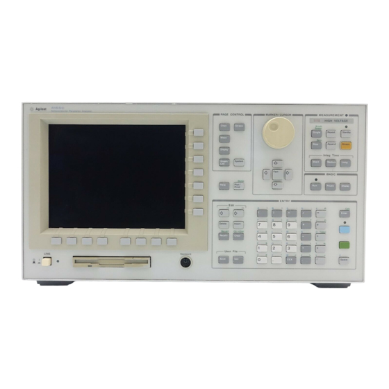
Use 3.5 inch diskette to load or store the analyzer settings and measurement data. • Keyboard connector You can use an IBM PC/AT compatible keyboard to operate the 4155C/4156C. See Chapter 6. • Help key Pressing Help key displays the help screens. - Page 28 Up, Down, Left, and Right. Moves field pointer or cursor. Fast key Moves the marker or cursor faster. When you rotate the rotary knob or press the arrow keys with holding Fast down, the marker or cursor moves faster. Agilent 4155C/4156C User’s Guide Vol.1, Edition 11...
- Page 29 Sets the integration time to SHORT, MEDIUM, or LONG, Long respectively. • MEASUREMENT indicator This indicator lights when the 4155C/4156C is in the measurement state. • HIGH VOLTAGE indicator This indicator lights when a unit forces more than 40 V. Agilent 4155C/4156C User’s Guide Vol.1, Edition 11...
- Page 30 Front View of the 4155C/4156C • Standby indicator This indicator lights when the 4155C/4156C is standby enabled, which means that the channels that are standby enabled (STBY ON) will return to the standby state after the measurement is finished. •...
-
Page 31: Rear View Of The 4155C/4156C
Introducing the 4155C/4156C Rear View of the 4155C/4156C Rear View of the 4155C/4156C Figure 1-2 Rear View of the 4155C/4156C Agilent 4155C/4156C User’s Guide Vol.1, Edition 11 1-11... - Page 32 5000-4206). For floating measurement, remove the shorting bar. CAUTION For floating measurement, do not apply voltage more than ± 42 V to the Circuit Common terminal. Failure to heed this caution may result in damage to the 4155C/ 4156C. WARNING If the Circuit Common terminal is not connected to the frame ground terminal (for floating measurement), a potential shock hazard may present.
- Page 33 • LAN interface RJ45 connector. Ethernet IEEE 802.3 10BASE-T for a 10M bps CSMA/CD local area network. The 4155C/4156C can be a NFS cluster, and can use a remote printer to make hardcopies. • Parallel interface 25-pin parallel I/O interface port for connecting peripheral such as a Centronics parallel printer.
-
Page 34: Front And Rear View Of The 41501A/B
Introducing the 4155C/4156C Front and Rear View of the 41501A/B Front and Rear View of the 41501A/B Figure 1-3 Front and Rear View of the 41501A 1-14 Agilent 4155C/4156C User’s Guide Vol.1, Edition 11... - Page 35 AC power cable is connected to this receptacle. • Serial number The 41501A/B has its own serial number. You need this serial number when using the telephone assistance program (Agilent Technologies HelpLine). • GNDU connector The GNDU connector is a triaxial connector: inner conductor is sense, middle conductor is force, and outer conductor is circuit common.
- Page 36 For details about PGU trigger, see User's Guide: Measurement and Analysis. • To SMU/Pulse Generator Selector Interface D-SUB 15-pin connector is used to control the 16440A SMU/pulse generator selector. 1-16 Agilent 4155C/4156C User’s Guide Vol.1, Edition 11...
- Page 37 41501A/B-410 has one HPSMU. Figure 1-5 Rear View of 41501A/B-410 • HPSMU terminals There are two triaxial connectors for Kelvin connections: one is for force and the other is for sense. For SMU5. Agilent 4155C/4156C User’s Guide Vol.1, Edition 11 1-17...
- Page 38 For details about PGU trigger, see User's Guide: Measurement and Analysis. • To SMU/Pulse Generator Selector Interface D-SUB 15-pin connector is used to control the 16440A SMU/pulse generator selector. 1-18 Agilent 4155C/4156C User’s Guide Vol.1, Edition 11...
- Page 39 Figure 1-7 Rear View of 41501A/B-420 • MPSMU terminals Two MPSMUs are installed and each MPSMU has a triaxial connector. These connectors are not designed for Kelvin connections. For SMU5 and SMU6. Agilent 4155C/4156C User’s Guide Vol.1, Edition 11 1-19...
- Page 40 For details about PGU trigger, see User's Guide: Measurement and Analysis. • To SMU/Pulse Generator Selector Interface D-SUB 15-pin connector is used to control the 16440A SMU/pulse generator selector. 1-20 Agilent 4155C/4156C User’s Guide Vol.1, Edition 11...
-
Page 41: Installation
Installation... - Page 42 • Before touching the connections on the Force, Guard, and Sense terminals, turn the 4155C/4156C off and discharge any capacitors. If you do not turn the 4155C/4156C off, complete all of the following items, regardless of the 4155C/4156C settings. •...
-
Page 43: Requirements
4155C/4156C/41501A, and 350 VA for the 41501B. For details, see Chapter 8. Power Cable CAUTION Before applying ac line power to the 4155C/4156C or the 41501A/B, ensure that the correct power cable is used. In accordance with international safety standards, this instrument is equipped with a three-prong power cable. - Page 44 PN: 8120-8376 • PN: 8120-4211, • PN: 8121-1866 8121-0564 • Plug: CNS 10917-2, • Plug: CS 0017:2003, 125 V, 10 A 250 V, 10 A • PN: 8120-6825, • PN: 8120-8871, 8121-1635 8121-1638 Agilent 4155C/4156C User’s Guide Vol.1, Edition 11...
-
Page 45: Line Fuse And Line Voltage Selector For The 41501A
Ventilation Requirements The 4155C/4156C has one cooling fan, and the 41501A/B has two cooling fans. To ensure adequate airflow, make sure that there is sufficient clearance around the cooling fans: 6 inches (150 mm) behind, 3 inches (70 mm) on the sides, and 0.5 inch (12 mm) above and below. -
Page 46: Operating Environment
Installation Requirements Operating Environment The 4155C/4156C and the 41501A/B are specified to operate within the following environmental conditions: 10 °C to 40 °C (with using flexible disk drive) 5 °C to 40 °C Temperature: (without using flexible disk drive) Humidity:... -
Page 47: Inspection
Installation Inspection Inspection This section describes what to do when you receive the 4155C/4156C and accessories. 1. Inspect the shipment. 2. Verify the 4155C/4156C operation. To maintain the 4155C/4156C and 41501A/B measurement accuracy specifications, perform calibration and adjustments once a year. -
Page 48: To Check The 4155C/4156C Operation
4. Connect the power cable from the 4155C/4156C to an ac power outlet. If the 41501A/B will be used, connect the power cable from the 41501A/B to the outlet. -
Page 49: To Set The Power Line Frequency
P A G E To Set the Power Line Frequency When the 4155C/4156C is shipped from the factory, the power line frequency is set to 60 Hz. To set the power line frequency correctly for your site, do following: 1. Turn on the 4155C/4156C. And wait until the CHANNELS: CHANNEL DEFINITION screen is appeared. -
Page 50: To Execute Diagnostics And Self-Calibration
To Execute Diagnostics and Self-calibration You can execute diagnostics and/or self-calibration to verify the operation of the 4155C/4156C. 1. Disconnect all cables from the measurement terminals on the 4155C/4156C rear panel. 2. Press System key, then CALIB/DIAG softkey. The SYSTEM: SELF-CALIBRATION/DIAGNOSTICS screen is displayed. -
Page 51: Connecting The 41501A/B Smu/Pulse Generator Expander
4155C/4156C, then attach it with the panel of the 4155C/4156C. thumbscrews. WARNING The 4155C/4156C, together with the 41501A/B, weights about 37 kg (81.8 lb). The 4155C/4156C is not anchored to the 41501A/B. Use caution when handling. Agilent 4155C/4156C User’s Guide Vol.1, Edition 11 2-11... -
Page 52: Installing Accessories
Installation Installing Accessories Installing Accessories This section describes how to install the 4155C/4156C and accessories. Additional information regarding airflow can be found in the “Ventilation Requirements” on page 2-5. This section describes how to: • install the 16442A/B test fixture •... -
Page 53: To Install The 16442A/B Test Fixture
Installing Accessories To Install the 16442A/B Test Fixture Before performing this procedure, turn off the 4155C/4156C and 41501A/B. When you use the 16442A/B test fixture without the 16441A R-box or the 16440A selector, you can stabilize the 16442A/B as shown in the figure below. - Page 54 Installation Installing Accessories Connecting the 4155C and the 16442A/B test fixture Connect the 4155C and the 16442A/B as shown below. CAUTION To prevent electrical shock during use, be sure to connect the interlock cable. 16442A/B 4. MPSMUs 2. VSUs 3. VMUs 1.
- Page 55 Guard terminals. To prevent electrical shock, do not expose these lines. CAUTION Never connect the Guard terminal to any output, including circuit common, chassis ground, or any other guard terminal. Doing so will damage the SMU. Agilent 4155C/4156C User’s Guide Vol.1, Edition 11 2-15...
- Page 56 NOTE Making non-Kelvin connection As same as the 4155C, the Force terminals can be used to force and measure dc voltage or current. If you want to simplify the cable connections, open the Sense terminals and connect the Force terminals only to the test fixture by using the triaxial cables.
- Page 57 The 16442A/B test fixture can be installed with an 16441A R-box, 16440A selector, or both. The following figure shows how to attach the 16442A/B to other accessories. 16442A/B Test Fixture 16441A R-BOX 16440A Selector Agilent 4155C/4156C User’s Guide Vol.1, Edition 11 2-17...
-
Page 58: To Install The 16441A R-Box
To Install the 16441A R-Box Before installing the 16441A R-box, turn off the 4155C/4156C and 41501A/B. 1. Connect the To R-Box terminal on the 4155C/4156C to the Control terminal on the 16441A rear panel using a 3.0 m or 1.5 m control cable. - Page 59 You can attach the 16441A R-box to the 16442A/B test fixture or to your shielding box, as shown in the following figures. Attaching the 16441A R-Box to the 16442A/B Test Fixture 16442A/B Test Fixture 16441A R-BOX Attaching the 16441A R-Box to the Shielding Box Agilent 4155C/4156C User’s Guide Vol.1, Edition 11 2-19...
-
Page 60: To Install The 16440A Smu/Pulse Generator Selector
Installation Installing Accessories To Install the 16440A SMU/Pulse Generator Selector To use the 16440A, the 4155C/4156C must be equipped with an 41501A/B SMU/pulse generator expander with two PGUs. • To attach the 16440A selector to the 16442A/B test fixture: 1. Place the 16440A selector on your 2. - Page 61 Place the 16440A selector and the 16442A/B test fixture on top of the second 16440A. 6. Position a plate on both sides. 7. Attach each plate using the three flathead screws supplied with the instrument. Agilent 4155C/4156C User’s Guide Vol.1, Edition 11 2-21...
- Page 62 To attach the 16440A selector to a shielding box: Units: mm The figure above shows the spacing of the 16440A screw holes. You need to prepare four screws and nuts to match the screw holes. 2-22 Agilent 4155C/4156C User’s Guide Vol.1, Edition 11...
- Page 63 1. Place the 16440A on your workbench. 2. Place the second 16440A on top of the 16440A. 3. Position a plate on both sides. 4. Attach each plate using the three flathead screws supplied with the instrument. Agilent 4155C/4156C User’s Guide Vol.1, Edition 11 2-23...
- Page 64 2. Place the 16440A(s) on the side panel of the shielding box. 3. Position four nuts on the inside panel of the shielding box. 4. Attach the angle bracket to the shielding box using four flathead screws. 2-24 Agilent 4155C/4156C User’s Guide Vol.1, Edition 11...
- Page 65 Installation Installing Accessories • To attach an 16441A R-box to the 16440A selector on the shielding box: Agilent 4155C/4156C User’s Guide Vol.1, Edition 11 2-25...
-
Page 66: To Connect The 16440A Selector To The 4155C/4156C
Installation Installing Accessories To Connect the 16440A Selector to the 4155C/4156C • Connecting two 16440A selectors If you use two 16440A, connect the Control Output terminal of the selector to the Control Input terminal of the second selector using a 40 cm control cable as shown below. - Page 67 Installation Installing Accessories • Connecting the 16440A selector to the 4155C/4156C Turn off the 4155C/4156C and 41501A/B before connecting the instruments. Then connect as shown below. 4155/4156 16442A/B Test Fixture 41501 16440A Selector 16440A Instrument Terminal Cable Terminal 41501A/B To SMU/Pulse CONTROL Input 3.0 m or 1.5 m Control Cable...
-
Page 68: To Connect The Measurement Cable To The Connector Plate
NOTE Making non-Kelvin connection (4156C) As same as the 4155C, the Force terminals of the 4156C can be used to force and measure dc voltage or current. If you want to simplify the cable connections, open the Sense terminals and connect the Force terminals only to the test fixture by using the triaxial cables. - Page 69 16495J INPUT 1 to 8 (for non-Kelvin) MPSMU 16495H INPUT 1 to 6 Triaxial Cable 16495J INPUT 1 to 8 16495H INPUT 7 to 12 BNC Cable 16495J INPUT 9 to 12 Agilent 4155C/4156C User’s Guide Vol.1, Edition 11 2-29...
- Page 70 Installing Accessories Connecting the interlock terminal The 4155C/4156C provides an interlock connector to prevent you from receiving an electrical shock from high voltage (more than ±40 V). If the interlock terminal is open, the 4155C/4156C cannot force high voltage more than ±40 V.
-
Page 71: Mounting Connectors
LED (V = 10 mA) 8150-5680 Wire Connecting GNDU to 1250-2457 Triaxial Connector (female) 8121-1189 or 8150-2639 Coaxial Cable or Wire Connecting SMU to 1250-2457 Triaxial Connector (female) 8121-1191 Low Noise Coaxial Cable Agilent 4155C/4156C User’s Guide Vol.1, Edition 11 2-31... - Page 72 Dimensions of Connector Holes Kelvin Triaxial Connector (in mm) Triaxial Connector (in mm) ∅11.3 10.3 2 − ∅11.3 ∅3.2 2 − M3 x 0.5 BNC Connector (in mm) Interlock Connector (in mm) 12.8 2-32 Agilent 4155C/4156C User’s Guide Vol.1, Edition 11...
-
Page 73: To Make An Interlock Circuit
Figure 2-2 shows the pin assignments of the interlock connector mounted on a connector plate or test fixture. Figure 2-2 Interlock Connector Pin Assignments WARNING Potentially hazardous voltages may be present at the Force, Guard, and Sense terminals when the interlock terminals are shorted. Agilent 4155C/4156C User’s Guide Vol.1, Edition 11 2-33... - Page 74 See Figure 2-2. If the 4155C/4156C Intlk connector is connected to the interlock circuit, the 4155C/4156C SMU cannot force more than ±40 V when the door is open. When the door is closed, it can force more than ±40 V.
- Page 75 Dimensions of the Interlock Switch (Agilent part number 3101-3241) 10.2 27.5 10.9 Switch off Switch on 15.9 Units: mm 27.8 UGI01012,85x60 Figure 2-5 Dimensions of the LED (Agilent part number 1450-0641) Units: mm UGI01013,50x50 Agilent 4155C/4156C User’s Guide Vol.1, Edition 11 2-35...
- Page 76 To Perform an Interlock Circuit Test To confirm that the interlock circuit is operating properly, perform the following test. 1. Connect the Intlk terminal of the 4155C/4156C to your interlock circuit. 2. Press System key, then select CALIB/DIAG softkey to display the SYSTEM: SELF-CALIBRATION/DIAGNOSTICS screen.
-
Page 77: To Connect The Gndu Output
Use Agilent 16493H GNDU cable to connect the GNDU to your connector plate or test fixture. Do not use the triaxial cable. The GNDU is rated for up to 1.6 A, while the maximum current rating of the triaxial cable is 1 A. Agilent 4155C/4156C User’s Guide Vol.1, Edition 11 2-37... -
Page 78: To Connect The Smu Output
DUT. Physically stabilize the cables with tape. Common Common Guard Guard Force Force Triaxial Coaxial cable Triaxial Coaxial cable Common Common connector connector Guard Guard Sense Sense Wire Insulator Insulator Plate Plate 2-38 Agilent 4155C/4156C User’s Guide Vol.1, Edition 11... - Page 79 Force, Sense, and Guard terminals. To prevent electrical shock, do not expose these lines. Before turning the 4155C/4156C on, connect the Intlk terminal to a switch that turns off when the shielding box access door is opened. Before you touch any connections to these terminals, turn the 4155C/4156C off, disconnect the power cable, and discharge any capacitors.
-
Page 80: To Connect The Vsu/Vmu/Pgu Outputs
DUT. If you use an 16440A selector, use a low-noise coaxial cable (Agilent part number 8121-1191). Common Common Signal line Signal line Insulator Insulator Coaxial cable Wire Plate Plate connector connector 2-40 Agilent 4155C/4156C User’s Guide Vol.1, Edition 11... -
Page 81: Connecting Instruments Or Peripherals
To Connect GPIB Instruments or Peripherals The 4155C/4156C has an GPIB interface for instrument, printer, or plotter control. • If you use an external controller with the 4155C/4156C, connect an GPIB cable between the controller and the 4155C/4156C. • If you control instruments using the 4155C/4156C built-in IBASIC capability, connect an GPIB cable between the instrument and the 4155C/4156C. -
Page 82: To Connect Parallel Peripherals
The 4155C/4156C has a 25 pin parallel I/O interface port for connecting peripherals, such as a Centronics parallel printer. To use a parallel printer, connect a parallel cable from the 4155C/4156C to the peripheral. You do not need to define any fields on the setup screen. -
Page 83: Maintenance
Installation Maintenance Maintenance Maintenance should be performed periodically to keep the 4155C/4156C and 41501A/B in good condition. Calibration Calibration and adjustments must be performed periodically so that the instruments satisfy the specifications, and keep a good condition. It is recommended to perform the calibration once a year at least. - Page 84 Installation Maintenance 2-44 Agilent 4155C/4156C User’s Guide Vol.1, Edition 11...
-
Page 85: Connecting To Network
Connecting to Network... - Page 86 This chapter explains how to connect to a network, and contains the following sections: • “Introduction” This section explains what the 4155C/4156C can do by connecting it to a network. • “Executing LAN Interface Test” This section explains how to execute the LAN interface test of the 4155C/4156C.
-
Page 87: Introduction
The 4155C/4156C cannot be controlled via the LAN interface. Note: The network file system cannot be mass-storage of the IBASIC of the 4155C/4156C. You cannot save IBASIC programs, BASIC binary and ASCII data to the network file system. Agilent 4155C/4156C User’s Guide Vol.1, Edition 11... -
Page 88: Executing Lan Interface Test
Executing LAN Interface Test Before connecting the 4155C/4156C to the network, you should check the operation of the LAN interface installed in the 4155C/4156C. Do this by executing the LAN interface test as shown below. 1. Turn the 4155C/4156C on. -
Page 89: Network Setup Parameters
If you access only a network within the subnet, set to 0.0.0.0. b. User ID must be unique for each user. After using the 4155C/4156C, set a meaningless value. If you do not change the value, any user can access the network file system using your user ID. -
Page 90: Setting Up 4155C/4156C
1. Turn off the 4155C/4156C. 2. Connect the 4155C/4156C to the network by using the straight LAN cable. If you are not connecting the 4155C/4156C to the network but to the server directly, use the cross LAN cable. 3. Turn on the 4155C/4156C. - Page 91 Full path name for HP-UX, or NFS sharing name for Windows. /D4156 or DATA4156 a. User ID must be unique for each user. After using the 4155C/4156C, set a meaningless value. If you do not change the value, any user can access the network file system using your user ID.
-
Page 92: Using Network
“Using Remote Printer” • “Saving Graphics Data” • “Saving Spreadsheet Data” Functions Connecting to a network, the 4155C/4156C can use a remote printer and a NFS server on the network. • To use a remote printer • To mount a NFS server To use a remote 1. - Page 93 Using Network Files and directories created by the 4155C/4156C The 4155C/4156C creates a file or a directory upon the following permission. After creating it, change the permission as you wish by using the NFS server. The 4155C/4156C cannot change the permission.
-
Page 94: Saving 4155C/4156C Setup Data
Saving 4155C/4156C Setup Data This example saves a setup data file to a network file system. Figure 3-3 shows the 4155C/4156C setup screen for saving measurement setup data with result data to the IDVG.DAT file in the C:\D4156 directory of the NFS server. -
Page 95: Using Remote Printer
* P R I N T / P L O T C O M M E N T H R P C L 1 0 0 D P I PRINTER/PLOTTER PRINT PR/PL EXIT PLOT SETUP Agilent 4155C/4156C User’s Guide Vol.1, Edition 11 3-11... -
Page 96: Saving Graphics Data
Using Network Saving Graphics Data This example saves a graphics data file to a network file system. Figure 3-5 shows the 4155C/4156C setup screen to save a measurement result graph to the IDVG.TIF file in the network file system. Figure 3-5... - Page 97 S e l e c t o n e o f t h e s e c o n d a r y s o f t k e y s . E X I T Figure 3-7 Importing Graphics Data Agilent 4155C/4156C User’s Guide Vol.1, Edition 11 3-13...
-
Page 98: Saving Spreadsheet Data
D E L I M I T E R C O M M A 1 < - - > M A X S T R I N G M A R K " " 3-14 Agilent 4155C/4156C User’s Guide Vol.1, Edition 11... - Page 99 Connecting to Network Using Network Figure 3-9 Reading Spreadsheet Data Agilent 4155C/4156C User’s Guide Vol.1, Edition 11 3-15...
-
Page 100: If You Use A Hp-Ux System
“Setting Up HP-UX System” Defining Network Parameters To connect the 4155C/4156C to the network of your site, the following network parameters are required. These parameters are usually assigned and managed by the network administrator. Contact the network administrator of your site, and acquire the parameter values. -
Page 101: Setting Up Hp-Ux System
• To enable NFS server and export a directory to the 4155C/4156C Host name and IP address of the 4155C/4156C are required. Previously acquire them from the network administrator. Previously decide the name, owner, and permission of the directory to export. -
Page 102: If You Use A Windows Pc
“Setting Up Network for Windows NT” • “Setting Up Print Server for Windows NT” • “Setting Up NFS Server” NOTE Setting up of network and servers must be performed by a member of the Windows Administrators group. 3-18 Agilent 4155C/4156C User’s Guide Vol.1, Edition 11... -
Page 103: Hardware/Software Required
Windows NT 4.0 SP4 or later (with Internet Explorer 4.01 or later). • LAN cable (1 ea., straight or cross) Use straight cable for connecting the computer to a network. Use cross cable for connecting the computer to the 4155C/4156C directly. • CD-ROM drive •... -
Page 104: Network Parameters Required
The DHCP server assigns the IP address automatically, and changes it dynamically. NOTE If you connect the computer to the 4155C/4156C directly and never connect to a local area network, assign the computer name and IP address by yourself. For the workgroup name, set WORKGROUP. -
Page 105: Setting Up Network For Windows Xp
2. Connect the computer to the network of your site using the straight LAN cable. If you are not going to connect the computer to the network but to the 4155C/4156C directly, use the cross LAN cable. 3. Turn on the computer and CD-ROM drive. Then wait until Windows boots up. - Page 106 2. Ping a computer or a device on the network. If, for example, the IP address of the device is 192.168.1.99, execute C:\> ping 192.168.1.99. If any error occurs, perform these instructions again. 3-22 Agilent 4155C/4156C User’s Guide Vol.1, Edition 11...
-
Page 107: Setting Up Print Server For Windows Xp
If the check box has not been selected, select the check box, click OK of the window, click Next of the wizard. After that, step through the setup instruction to install the Print Services for Unix. 6. Click Close of the Add or Remote Programs window. Agilent 4155C/4156C User’s Guide Vol.1, Edition 11 3-23... - Page 108 Do not forget sharing the printer, and its share name used to specify the printer. For the share name, a maximum 15 alphanumeric characters is available. The first character must be a letter of the alphabet. 3-24 Agilent 4155C/4156C User’s Guide Vol.1, Edition 11...
-
Page 109: Setting Up Network For Windows 2000
2. Connect the computer to the network of your site using the straight LAN cable. If you are not going to connect the computer to the network but to the 4155C/4156C directly, use the cross LAN cable. 3. Turn on the computer and CD-ROM drive. Then wait until Windows boots up. - Page 110 TCP/IP. 5. Highlight Internet Protocol (TCP/IP). Figure 3-10 Selecting Network Protocol Local Status Local Properties Network and Dial-up Connect using: Connection Components xxxx Activity xxxx TCP/IP Install Local Area Connection Properties 3-26 Agilent 4155C/4156C User’s Guide Vol.1, Edition 11...
- Page 111 TCP/IP Properties Local Properties Connect using: Connection Obtain automatically Use following IP Example: Components 192.168. 1. 1 IP Address xxxx Subnet Mask Activity 255.255.255. 0 xxxx Gateway 192.168. 1. 3 TCP/IP Properties Close Agilent 4155C/4156C User’s Guide Vol.1, Edition 11 3-27...
-
Page 112: Setting Up Print Server For Windows 2000
If the check box has not been selected, select the check box, click OK of the window, click Next of the wizard. After that, step through the setup instruction to install the Print Services for Unix. 6. Click Close of the Add/Remote Programs window. 3-28 Agilent 4155C/4156C User’s Guide Vol.1, Edition 11... - Page 113 Do not forget sharing the printer, and its share name used to specify the printer. For the share name, a maximum 15 alphanumeric characters is available. The first character must be a letter of the alphabet. Agilent 4155C/4156C User’s Guide Vol.1, Edition 11 3-29...
-
Page 114: Setting Up Network For Windows Nt
You check the network identification. Step 3. Network Protocols You set the network protocol. Step 4. TCP/IP Properties You set up the TCP/IP properties. Step 5. Network Connection Check You check the network connection. 3-30 Agilent 4155C/4156C User’s Guide Vol.1, Edition 11... - Page 115 2. Connect the computer to the network of your site using the straight LAN cable. If you are not going to connect the computer to the network but to the 4155C/4156C directly, use the cross LAN cable. 3. Turn on the computer and CD-ROM drive. Then wait until Windows boots up.
- Page 116 TCP/IP Properties IP Address Tab Adapter TCP/IP Protocol xx Adapter xxxx Obtain from DHCP xxxx Specify IP address Example: 192.168. 1. 1 IP Address Subnet Mask 255.255.255. 0 Gateway 192.168. 1. 3 Properties 3-32 Agilent 4155C/4156C User’s Guide Vol.1, Edition 11...
-
Page 117: Setting Up Print Server For Windows Nt
TCP/IP Printing service. 4. Click OK. Figure 3-15 Confirming Network Services Services Tab Network 3 To add the TCP/IP printing service Select Network Service TCP/IP Printing xxxx xxxx xxxx Microsoft TCP/IP Printing Agilent 4155C/4156C User’s Guide Vol.1, Edition 11 3-33... - Page 118 Do not forget sharing the printer, and its share name used to specify the printer. For the share name, a maximum 15 alphanumeric characters is available. The first character must be a letter of the alphabet. 3-34 Agilent 4155C/4156C User’s Guide Vol.1, Edition 11...
-
Page 119: Setting Up Nfs Server
Step 10. Export (Windows Explorer) You export a network file system. a. The password file and group file are used for the user mapping between a NFS server and a NFS client. Agilent 4155C/4156C User’s Guide Vol.1, Edition 11 3-35... - Page 120 User ID and group ID defined in the password file and group file are important. They must be set to the 4155C/4156C when it mounts to a network file system on the NFS server. A numeric value from 1 to 32767 is available for the 4155C/4156C.
- Page 121 3. Click Settings tab, and fill in the following field. Field Name Description Example Computer name Name of the computer used for user PC001 name mapping between Windows and Unix. 4. Click Apply. Agilent 4155C/4156C User’s Guide Vol.1, Edition 11 3-37...
- Page 122 Primary group name Group name the user belongs. Users User ID (UID) User ID. Not used by 4155C/4156C. 1001 4. Repeat 3 for all users you want to register. 5. Click Apply. 3-38 Agilent 4155C/4156C User’s Guide Vol.1, Edition 11...
- Page 123 7. Select a Windows user name and an UNIX user name to associate, then click Add. For example, set as shown below: Windows user name UNIX user name USER01 user01 8. Repeat 7 for all users you want to register. 9. Click Apply. Agilent 4155C/4156C User’s Guide Vol.1, Edition 11 3-39...
- Page 124 7. Select a Windows group name and an UNIX group name to associate, then click Add. For example, set as shown below: Windows group name UNIX group name Users users 8. Repeat 7 for all groups you want to register. 9. Click Apply. 3-40 Agilent 4155C/4156C User’s Guide Vol.1, Edition 11...
- Page 125 Finally, close the Services for UNIX Administration window to complete the setup of the NFS server. You may need to restart the computer. Then restart the computer, and log on to Windows again. Agilent 4155C/4156C User’s Guide Vol.1, Edition 11 3-41...
- Page 126 Select the Share this folder radio button. b. Enter Share name, for example, DATA4156. This value will be set to the 4155C/4156C to specify the network file system to mount. It must be a maximum 58 alphanumeric characters. c. Click Permissions to open the NFS Share Permissions dialog box.
- Page 127 This example sets the permission of the folder D4156 as shown below. Permission of D4156 USER01 (creator) Full Control Users (group) Read Everyone Read Then the 4155C/4156C (for example, host name ANALYZER) will be able to mount a folder you specified. Agilent 4155C/4156C User’s Guide Vol.1, Edition 11 3-43...
- Page 128 Connecting to Network If You Use a Windows PC 3-44 Agilent 4155C/4156C User’s Guide Vol.1, Edition 11...
-
Page 129: File Operations
File Operations... - Page 130 • backing up a diskette You can use these file operations on the internal memory, a diskette in the built-in flexible disk drive, or on a network file system that Agilent 4155C/4156C mounts. You can perform file operations by: •...
- Page 131 File Operations NOTE To Use the Network File System The 4155C/4156C can be an NFS client, and can use the network file system as a mass storage device. To use the network file system: 1. Connect the 4155C/4156C to your LAN. See Chapter 3.
-
Page 132: Selecting A Mass Storage Device
Before selecting one of these directories, it must be exported so that it can be mounted by the 4155C/4156C. When this softkey is pressed, the 4155C/4156C mounts the directory on an NFS server, and displays the file catalog in the FILE CATALOG area. -
Page 133: Listing A File Catalog
To Exit the File Catalog Select EXIT FILE CATALOG softkey. To Search for a Desired File Name Enter an alphanumeric character. The cursor will move to the first file name that starts with that character. Agilent 4155C/4156C User’s Guide Vol.1, Edition 11... -
Page 134: Storing Setup Or Results Data
To store data in an existing file, select FILE CATALOG softkey. Use the rotary knob to move the cursor to the correct file, then press SELECT softkey. • To store data in an internal memory, select MEM1, MEM2, MEM3 or MEM4 softkey. Agilent 4155C/4156C User’s Guide Vol.1, Edition 11... - Page 135 (When using internal memory, the specified comment will be displayed on the softkey.) 6. Select EXECUTE softkey. The data will be stored in the specified file. Any data previously stored in the existing file or internal memory will be overwritten. 7. Select EXIT softkey. Agilent 4155C/4156C User’s Guide Vol.1, Edition 11...
-
Page 136: Storing Results Data In Spreadsheet Format
If the UNIT is ON, results data will be treated as string data. • OFF softkey will not save the units of measure. Results data will be treated as numeric data. With UNIT ON or OFF, invalid data (----) will be treated as string data. Agilent 4155C/4156C User’s Guide Vol.1, Edition 11... - Page 137 ‘ ’ ‘ ’ 9. Select EXECUTE softkey. The results data will be saved to the specified file, and a .TXT extension is automatically added. 10. Select EXIT softkey. Agilent 4155C/4156C User’s Guide Vol.1, Edition 11...
-
Page 138: Output Format For The Ascii Save Function
, DELIMITER=COMMA) “ ” “VCE=”,0.0001,“to”,1,“in”,“LOG”,“step” For sampling measurements: Format: @TIME = <start time> to <stop time> Type: [S/N] [S/N] • Example (setups: UNIT=ON, STRING MARK = , DELIMITER=COMMA) “ ” “@TIME=”,“0.00 s”,“to”,“1.516 s” 4-10 Agilent 4155C/4156C User’s Guide Vol.1, Edition 11... - Page 139 Format: <blank><1st variable unit><2nd variable unit> Type: • Example (setups: STRING MARK= , DELIMITER=COMMA) “ ” “”,“V”,“A” 6. measurement data Format: <index><1st variable data><2nd variable data> Type: [S/N] [S/N] • Example (setups: UNIT=OFF, DELIMITER=COMMA) 1,0.001,-9.265E-10,...,... Agilent 4155C/4156C User’s Guide Vol.1, Edition 11 4-11...
-
Page 140: Output Examples
DELIMITER = TAB • STRING MARK = NONE • Output V3-I3 characteristics V3 = 0 to 1 in 0.1 step I3 = 2E-05 to 0.0001 in 2E-05 step 1.665E-09 1.9072E-09 1.4471E-08 1.8823E-07 2.1995E-06 4-12 Agilent 4155C/4156C User’s Guide Vol.1, Edition 11... - Page 141 I2 = 2E-05 to 0.0001 in 2E-05 step <--Append2 --+--Single 4.3E-13 5.7E-13 3.1E-13 3.2E-13 /* Append 1 */ --+--Append1 1.7E-13 8E-13 2.8E-13 4.5E-13 /* Append 2 */ --+--Append2 1.5E-13 7E-13 2.5E-13 5E-13 Agilent 4155C/4156C User’s Guide Vol.1, Edition 11 4-13...
-
Page 142: Loading Setup Or Results Data
Press SELECT softkey. This sets the NAME and TYPE entries. • To load data from internal memory, select MEM1, MEM2, MEM3 or MEM4 softkey. 4. Select EXECUTE softkey. 5. Select EXIT softkey. 4-14 Agilent 4155C/4156C User’s Guide Vol.1, Edition 11... - Page 143 • Current Measurement Range: 1 A ⇒ 100 mA • • If you try to load an 4156A/B setup on the 4155C, one parameter will be changed: Current Measurement Range: 10 pA or 100 pA ⇒ 1 nA • File Type...
-
Page 144: Changing A File Name
Select FILE CATALOG softkey, and move the pointer to the desired file name using the rotary knob. Then press SELECT TARGET softkey. 9. Select EXECUTE softkey. The file name will be changed to the specified new name. 10. Select EXIT softkey. 4-16 Agilent 4155C/4156C User’s Guide Vol.1, Edition 11... -
Page 145: Removing A File/Directory
For example, if the NAME field is MOS1 and the TYPE field is *, then all the following files would be deleted: MOS1.MES MOS1.STR MOS1.DAT MOS1.MAT MOS1.CST MOS1.PRO Agilent 4155C/4156C User’s Guide Vol.1, Edition 11 4-17... -
Page 146: Copying A File
6. To copy a file from one diskette to another diskette: a. Move the pointer to the TARGET DISK field. b. Select OTHER softkey. (SAME softkey will copy the file back onto the source diskette.) 4-18 Agilent 4155C/4156C User’s Guide Vol.1, Edition 11... - Page 147 Insert the source diskette in the disk drive, then select this softkey. Suspends the copy operation. Insert Target Diskette. Continue? (YES / NO) Insert the target diskette in the disk drive, then select this softkey. Suspends the copy operation. 10. Select EXIT softkey. Agilent 4155C/4156C User’s Guide Vol.1, Edition 11 4-19...
-
Page 148: Creating A Directory On A Network File System
5. In the NAME field, enter the new directory name. The directory name can be 36 characters maximum. The directory name and directory path combined can be 58 characters maximum. 6. Select EXECUTE softkey. 7. Select EXIT softkey. 4-20 Agilent 4155C/4156C User’s Guide Vol.1, Edition 11... -
Page 149: Changing The Working Directory
6. To change the working directory to the upper level, select one of the following: UPPER DIR Moves to the directory one level higher than the current directory. ROOT DIR Moves to the root directory. 7. Select EXIT FILE CATALOG softkey. Agilent 4155C/4156C User’s Guide Vol.1, Edition 11 4-21... -
Page 150: Initializing A Diskette
10. After the confirmation message, insert a diskette in the flexible disk drive, then select: • YES softkey to initialize the diskette. • NO softkey to cancel. The PROGRESS STATUS field shows what percentage of the initialization is completed. 11. Select EXIT softkey. 4-22 Agilent 4155C/4156C User’s Guide Vol.1, Edition 11... -
Page 151: Backing Up A Diskette
The internal memory capacity may not be sufficient to perform the entire disk copy. If so, swap the source and target disks according to the on-screen instructions. 9. Select EXIT softkey. Agilent 4155C/4156C User’s Guide Vol.1, Edition 11 4-23... - Page 152 File Operations Backing Up a Diskette 4-24 Agilent 4155C/4156C User’s Guide Vol.1, Edition 11...
-
Page 153: Print/Plot Function
Print/Plot Function... - Page 154 Print/Plot Function Agilent 4155C/4156C print/plot function enables you to print, plot, or save to a file the following types of data: • Screen images from the 4155C/4156C display • Lists of setup data from the setup screens (except for the GRAPH/LIST and KNOB SWEEP screens) •...
-
Page 155: Output Formats
Saving measurement data lists to a file GRAPH/LIST: LIST Saving measurement data graphs to a file GRAPH/LIST: GRAPHICS, PCL, HR PCL, HP-GL or KNOB SWEEP HR TIFF 1. All setup screens, except for GRAPH/LIST and KNOB SWEEP. Agilent 4155C/4156C User’s Guide Vol.1, Edition 11... -
Page 156: Differences Between Pcl, Hr Pcl And Hp-Gl
RESOLUTION setting. All fonts are scaled with the output region. HP-GL Position, size and aspect ratio are defined by OUTPUT REGION. All fonts are scaled with the output region. Print speed is faster than PCL. Agilent 4155C/4156C User’s Guide Vol.1, Edition 11... -
Page 157: Output Resolution
RESOLUTION and UPPER LEFT settings are automatically calculated and displayed in the fields. You cannot change the aspect ratio of the output. If the value exceeds 100%, change the RESOLUTION or UPPER LEFT settings. The value must be 0% to 100%. Agilent 4155C/4156C User’s Guide Vol.1, Edition 11... -
Page 158: Supported Peripherals
Print/Plot Function Supported Peripherals Supported Peripherals The 4155C/4156C supports the following peripherals. Use the table below to select the printer or plotter that best meets your needs. Output Resolution Model Interface Output Format Color (dpi) HP DeskJet 340 Parallel PCL, HR PCL... -
Page 159: Connecting Peripherals
For more information on connecting peripherals, see “Connecting Instruments or Peripherals” in Chapter 2. If you use a remote printer via your printer server, connect the 4155C/4156C to your LAN. For more information, see Chapter 3 and Setup Screen Reference manual. -
Page 160: Printing/Plotting Screen Images
Before beginning to print/plot, check the following: • SYSTEM: MISCELLANEOUS screen This screen specifies the 4155C/4156C control mode, GPIB address, output equipment, and so on. Set all the entry fields properly. For more information, see Setup Screen Reference manual. •... - Page 161 To make a hard copy of a screen image: 1. Display the screen that you want to print out, then press: a. the front-panel green key b. Plot/Print key The 4155C/4156C displays the SCREEN DUMP dialog box. SCREEN DUMP *DESTINATION PRINTER/PLOTTER...
- Page 162 *OUTPUT REGION UPPER LEFT <--origin of printer LOWER RIGHT X 100% 5. To start the screen dump, select PRINT/PLOT softkey. 6. To close the SCREEN DUMP dialog box, select EXIT softkey. 5-10 Agilent 4155C/4156C User’s Guide Vol.1, Edition 11...
-
Page 163: Printing/Plotting Setup Data Lists
Before beginning to print/plot, check the following: • SYSTEM: MISCELLANEOUS screen This screen specifies the 4155C/4156C control mode, GPIB address, output equipment, and so on. Set all the entry fields properly. For more information, see Setup Screen Reference manual. •... - Page 164 Printing/Plotting Setup Data Lists To print/plot the setup data list: 1. Display the setup screen you want to print/plot, then press: • Plot/Print key The 4155C/4156C displays the PRINT/PLOT SETUP DATA dialog box. PRINT/PLOT SETUP DATA *DESTINATION PRINTER/PLOTTER *OUTPUT REGION...
- Page 165 COMMENT field. This comment is printed only when this field is enabled on the SYSTEM: PRINT/PLOT SETUP screen. 7. To start printing/plotting, select PRINT/PLOT softkey. 8. To close the PRINT/PLOT SETUP DATA dialog box, select EXIT softkey. Agilent 4155C/4156C User’s Guide Vol.1, Edition 11 5-13...
-
Page 166: Printing/Plotting Measurement Data Lists
Before beginning to print/plot, check the following: • SYSTEM: MISCELLANEOUS screen This screen specifies the 4155C/4156C control mode, GPIB address, output equipment, and so on. Set all the entry fields properly. For more information, see Setup Screen Reference manual. •... - Page 167 Printing/Plotting Measurement Data Lists To print/plot the measurement result list: 1. Display the GRAPH/LIST: LIST screen, then press: • Plot/Print key The 4155C/4156C displays the PRINT/PLOT DATA LIST dialog box. PRINT/PLOT DATA LIST *DESTINATION PRINTER/PLOTTER *OUTPUT REGION *OUTPUT DATA(INDEX NO) UPPER LEFT <-->...
- Page 168 COMMENT field. This comment is printed only when this field is enabled on the SYSTEM: PRINT/PLOT SETUP screen. 7. To start printing/plotting, select PRINT/PLOT softkey. 8. To close the PRINT/PLOT DATA LIST dialog box, select EXIT softkey. 5-16 Agilent 4155C/4156C User’s Guide Vol.1, Edition 11...
-
Page 169: Printing/Plotting Measurement Data Graphs
Before beginning to print/plot, check the following: • SYSTEM: MISCELLANEOUS screen This screen specifies the 4155C/4156C control mode, GPIB address, output equipment, and so on. Set all the entry fields properly. For more information, see Setup Screen Reference manual. •... - Page 170 Print/Plot Function Printing/Plotting Measurement Data Graphs To print/plot a measurement result graph: 1. Display the GRAPH/LIST: GRAPHICS screen, then press: • Plot/Print key The 4155C/4156C displays the GRAPH PLOT dialog box. GRAPH PLOT *DESTINATION PRINTER/PLOTTER *OUTPUT REGION UPPER LEFT *PRINT SETUP DATA YES...
- Page 171 UPPER LEFT Specifies the position of the upper-left corner of the printed or plotted hard copy. LOWER RIGHT Specifies the position of the lower-right corner of the printed or plotted hard copy. Agilent 4155C/4156C User’s Guide Vol.1, Edition 11 5-19...
- Page 172 COMMENT field. This comment is printed only when this field is enabled on the SYSTEM: PRINT/PLOT SETUP screen. 8. To start printing/plotting, select PRINT/PLOT softkey. 9. To close the GRAPH PLOT dialog box, select EXIT softkey. 5-20 Agilent 4155C/4156C User’s Guide Vol.1, Edition 11...
-
Page 173: Saving Screen Images
TIFF TIFF DESTINATION √ √ √ FORM FEED LINE COLUMN √ √ √ √ √ COLOR/B/W √ √ √ PAPER OUTPUT ITEM √ √ √ INIT STRING √ √ √ TRAILER STRING Agilent 4155C/4156C User’s Guide Vol.1, Edition 11 5-21... - Page 174 Saving Screen Images To save the screen images: 1. Display the screen that you want to print out, then press: a. the front-panel green key b. Plot/Print key The 4155C/4156C displays the SCREEN DUMP dialog box. SCREEN DUMP *DESTINATION FILE *FILE NAME...
- Page 175 *OUTPUT REGION UPPER LEFT <--origin of printer LOWER RIGHT X 100% 6. To start to save the screen image, select PRINT/PLOT softkey. 7. To close the SCREEN DUMP dialog box, select EXIT softkey. Agilent 4155C/4156C User’s Guide Vol.1, Edition 11 5-23...
-
Page 176: Saving Setup Data Lists
FORM FEED √ √ √ LINE √ √ COLUMN √ √ √ COLOR/B/W √ √ √ PAPER √ √ √ OUTPUT ITEM √ √ √ INIT STRING √ √ √ TRAILER STRING 5-24 Agilent 4155C/4156C User’s Guide Vol.1, Edition 11... - Page 177 Saving Setup Data Lists To save the setup data list: 1. Display the setup screen you want to save, then press: • Plot/Print key The 4155C/4156C displays the PRINT/PLOT SETUP DATA dialog box: PRINT/PLOT SETUP DATA *DESTINATION FILE *FILE NAME...
- Page 178 Sets the output region to the upper-right quarter of the paper. LOWER LEFT Sets the output region to the lower-left quarter of the paper. LOWER RIGHT Sets the output region to the lower-right quarter of the paper. 5-26 Agilent 4155C/4156C User’s Guide Vol.1, Edition 11...
- Page 179 COMMENT field. This comment is printed only when this field is enabled on the SYSTEM: PRINT/PLOT SETUP screen. 8. To start the file save, select PRINT/PLOT softkey. 9. To close the PRINT/PLOT SETUP DATA dialog box, select EXIT softkey. Agilent 4155C/4156C User’s Guide Vol.1, Edition 11 5-27...
-
Page 180: Saving Measurement Data Lists
FORM FEED √ √ √ LINE √ √ COLUMN √ √ √ COLOR/B/W √ √ √ PAPER √ √ √ OUTPUT ITEM √ √ √ INIT STRING √ √ √ TRAILER STRING 5-28 Agilent 4155C/4156C User’s Guide Vol.1, Edition 11... - Page 181 Saving Measurement Data Lists To save the measurement result list: 1. Display the GRAPH/LIST: LIST screen, then press: • Plot/Print key The 4155C/4156C displays the PRINT/PLOT DATA LIST dialog box. PRINT/PLOT DATA LIST *DESTINATION FILE *FILE NAME *OUTPUT DATA(INDEX NO) <-->...
- Page 182 Sets the output region to the upper-right quarter of the paper. LOWER LEFT Sets the output region to the lower-left quarter of the paper. LOWER RIGHT Sets the output region to the lower-right quarter of the paper. 5-30 Agilent 4155C/4156C User’s Guide Vol.1, Edition 11...
- Page 183 COMMENT entry field. This comment is printed only when this field is enabled on the SYSTEM: PRINT/PLOT SETUP screen. 8. To start the file save, select PRINT/PLOT softkey. 9. To close the PRINT/PLOT DATA LIST dialog box, select EXIT softkey. Agilent 4155C/4156C User’s Guide Vol.1, Edition 11 5-31...
-
Page 184: Saving Measurement Data Graphs
√ √ √ LINE √ √ COLUMN √ √ √ √ COLOR/B/W √ √ √ PAPER √ √ √ √ OUTPUT ITEM √ √ √ INIT STRING √ √ √ TRAILER STRING 5-32 Agilent 4155C/4156C User’s Guide Vol.1, Edition 11... - Page 185 Print/Plot Function Saving Measurement Data Graphs To save a measurement result graph: 1. Display the GRAPH/LIST: GRAPHICS screen, then press Plot/Print key. The 4155C/4156C displays the GRAPH PLOT dialog box. GRAPH PLOT *DESTINATION FILE *FILE NAME *OUTPUT REGION UPPER LEFT...
- Page 186 75 DPI to 600 DPI. For more information on selecting the resolution, see “Output Resolution” on page 5-5. If you select the HR PCL mode, setting the resolution too low will result in poor print quality. 5-34 Agilent 4155C/4156C User’s Guide Vol.1, Edition 11...
- Page 187 Sets the output region to the lower-right quarter of the paper. STORE REGION Stores the OUTPUT REGION settings in the internal memory. RECALL REGION Recalls the latest settings stored in the internal memory. Agilent 4155C/4156C User’s Guide Vol.1, Edition 11 5-35...
- Page 188 COMMENT field. This comment is printed only when this field is enabled on the SYSTEM: PRINT/PLOT SETUP screen. 9. To start printing/plotting, select PRINT/PLOT softkey. 10. To close the GRAPH PLOT dialog box, select EXIT softkey. 5-36 Agilent 4155C/4156C User’s Guide Vol.1, Edition 11...
-
Page 189: Output Examples
Print/Plot Function Output Examples Output Examples This section shows examples of the 4155C/4156C print/plot output. • “Screen Dump Output” • “Setup Data List Output” • “Measurement Result List Output” • “Measurement Result Graph Output” Agilent 4155C/4156C User’s Guide Vol.1, Edition 11... -
Page 190: Screen Dump Output
*PAPER SIZE FEED DIR LONG SIDE *INIT STRING \0033&l1O\0033%0B *TRAILER STRING \0033%A\0033&l0O • SCREEN DUMP dialog: SCREEN DUMP *DESTINATION PRINTER/PLOTTER *OUTPUT REGION UPPER LEFT LOWER RIGHT X 100% Y 100% *LANGUAGE HP-GL 5-38 Agilent 4155C/4156C User’s Guide Vol.1, Edition 11... - Page 191 Print/Plot Function Output Examples Output Example Agilent 4155C/4156C User’s Guide Vol.1, Edition 11 5-39...
-
Page 192: Setup Data List Output
SHORT SIDE *OUTPUT ITEM ENABLE for all • PRINT/PLOT SETUP DATA dialog: PRINT/PLOT SETUP DATA *DESTINATION PRINTER/PLOTTER *OUTPUT REGION UPPER LEFT *OUTPUT PAGE CURRENT *LANGUAGE *RESOLUTION *PRINT/PLOT COMMENT 75 DPI SAMPLE DEVICE 1 5-40 Agilent 4155C/4156C User’s Guide Vol.1, Edition 11... - Page 193 SERIES UNIT VNAME INAME MODE FCTN RESISTANCE SMU1:HR COMMON CONST 0 ohm SMU2:HR VAR1 O ohm SMU3:HR CONST SMU4:HR VAR2 VSU1 ------- VSU2 ------- VMU1 ------- ---- ----- VMU2 ------- ---- ----- Agilent 4155C/4156C User’s Guide Vol.1, Edition 11 5-41...
-
Page 194: Measurement Result List Output
*OUTPUT ITEM ENABLE for all • PRINT/PLOT DATA LIST dialog: PRINT/PLOT DATA LIST *DESTINATION PRINTER/PLOTTER *OUTPUT REGION *OUTPUT DATA(INDEX NO) UPPER LEFT <--> *LANGUAGE *RESOLUTION *PRINT/PLOT COMMENT 75 DPI SAMPLE DEVICE 1 5-42 Agilent 4155C/4156C User’s Guide Vol.1, Edition 11... - Page 195 1.500mV 3.07660mA 2.200 V 8.27044mA • Last sheet: *** Agilent 4156C DATA LIST *** Jan 10 20:00:00 2001 PAGE 3 ID-VG CHARACTERISTICS SAMPLE DEVICE1 MARKER POSITION : DATA# 1 [ 1/1 ] Agilent 4155C/4156C User’s Guide Vol.1, Edition 11 5-43...
-
Page 196: Measurement Result Graph Output
GRAPH PLOT dialog: GRAPH PLOT *DESTINATION PRINTER/PLOTTER *OUTPUT REGION *GRAPH TRACE ONLY UPPER LEFT *PRINT SETUP DATA LOWER RIGHT X 100% Y 100% POSITION BOTTOM *LANGUAGE *PRINT/PLOT COMMENT HP-GL SAMPLE DEVICE 1 5-44 Agilent 4155C/4156C User’s Guide Vol.1, Edition 11... - Page 197 NAME SOURCE 2.0000 V --------- --------- --------- NOTE PCL Mode Output If you select the PCL mode, the font size of the header line, comment and setup data depends on the printer. Agilent 4155C/4156C User’s Guide Vol.1, Edition 11 5-45...
- Page 198 Print/Plot Function Output Examples 5-46 Agilent 4155C/4156C User’s Guide Vol.1, Edition 11...
-
Page 199: External Keyboard
External Keyboard... - Page 200 External Keyboard You can operate Agilent 4155C/4156C from an external keyboard instead of by pressing front-panel keys and softkeys. This chapter describes the correspondence between front-panel keys/softkeys and the external keyboard. For functions of front-panel keys, refer to “Overview” in Chapter 1.
- Page 201 ⇒ → MARKER/CURSOR key group ⇑ ↑ ⇓ ↓ + ← Fast Shift + ⇒ + → Fast Shift + ⇑ + ↑ Fast Shift + ⇓ + ↓ Fast Shift Agilent 4155C/4156C User’s Guide Vol.1, Edition 11...
- Page 202 ENTRY key group Enter Enter green key+ Enter Shift Enter space bar Space Other front-panel keys (except for Ω , ° (deg), blue key, and green key) correspond to same keys on the external keyboard. Agilent 4155C/4156C User’s Guide Vol.1, Edition 11...
- Page 203 Initial Settings...
- Page 204 4155C/4156C. • default initial settings If you turn on the 4155C/4156C without a diskette, the 4155C/4156C is set to the default initial settings. In this condition, internal memories contain measurement setup data for the most common applications.
- Page 205 Initial Settings User-Defined Initial Settings User-Defined Initial Settings If you turn on an 4155C/4156C with a diskette in the flexible disk drive, the 4155C/4156C automatically loads the following files from the diskette: • files for setting setup and result screens The fields of the setup and result screens are automatically set according to the files on the diskette.
- Page 206 The CHANNELS: CHANNEL DEFINITION screen is always displayed after getting the files. Files for setting internal memories If the following files exist on diskette, they are loaded automatically from diskette to internal memory after you turn on the 4155C/4156C: • measurement setup files (MEM.MES) •...
-
Page 207: Measurement Units
Default Initial Settings Default Initial Settings When you turn on the 4155C/4156C without a diskette, the 4155C/4156C is set the default initial settings after finishing the power on test. The default initial settings, except for system screen group, are also set by selecting DEFAULT MEASURE SETUP secondary softkey in the MEASUREMENT MODE field on the CHANNELS: CHANNEL DEFINITION screen. - Page 208 You can select the secondary softkeys for the above applications when the pointer is in the MEASUREMENT MODE field on the CHANNELS: CHANNEL DEFINITION screen. The softkeys set the setup scteens for the application, thus saving time. Agilent 4155C/4156C User’s Guide Vol.1, Edition 11...
- Page 209 Specifications...
- Page 210 This chapter lists complete specifications and supplemental information of Agilent 4155C/4156C and Agilent 41501B. The specifications are the performance standards or limits against which the 4155C/4156C and 41501B are tested. When the 4155C/4156C and 41501B is shipped from the factory, it meets the specifications.
- Page 211 3. Ambient temperature changes less than ±1 °C after auto calibration execution. 4. Integration time: medium or long 5. Filter: ON (for SMUs) 6. Kelvin connection (for HRSMU, HPSMU, and GNDU) 7. Calibration period: 1 year Agilent 4155C/4156C User’s Guide Vol.1, Edition 11...
- Page 212 (for opposite polarity) For 10 pA to 10 nA range: V/I setting accuracy ± 12 % of range For 100 nA to 100 mA range: V/I setting accuracy ± 2.5 % of range Agilent 4155C/4156C User’s Guide Vol.1, Edition 11...
-
Page 213: Specifications
The accuracy is applicable when offset cancellation has been performed. The offset current specification is multiplied by one of the following factors depending upon the ambient Table 8-2 temperature and humidity. See Agilent 4155C/4156C User’s Guide Vol.1, Edition 11... - Page 214 (20 V < Vout ≤ 40 V) 20 mA (40 V < Vout ≤ 100 V) a. Accuracy: ± (% of reading or setting value + offset value). b. Vout is the output voltage in volts. Agilent 4155C/4156C User’s Guide Vol.1, Edition 11...
- Page 215 Voltage source: 0.03 % of V range Current source: 1 % of I range Range switching transient noise (typical, filter ON) Voltage ranging: 250 mV Current ranging: 10 mV Slew rate maximum 0.2 V/μs Agilent 4155C/4156C User’s Guide Vol.1, Edition 11...
- Page 216 Specification is applicable under no load current. • VSU supplemental information Output resistance typical 0.2 Ω Capacitive load maximum 10 μ Slew rate maximum 0.2 V/ μ Current limit typical 120 mA Output Noise typical 1 mV rms Agilent 4155C/4156C User’s Guide Vol.1, Edition 11...
- Page 217 500 pA (at 0 V) Measurement noise typical 0.01 % of range (p-p). when the integration time is 10 PLC. Differential mode measurement noise typical 0.005 % of range (p-p). when the integration time is short. Agilent 4155C/4156C User’s Guide Vol.1, Edition 11...
- Page 218 (for opposite polarity) For 1 nA to 10 nA range: V/I setting accuracy ± 12 % of range For 100 nA to 100 mA range: V/I setting accuracy ± 2.5 % of range 8-10 Agilent 4155C/4156C User’s Guide Vol.1, Edition 11...
- Page 219 (50mA < Iout ≤ 100mA) a. Accuracy: ± (% of reading or setting value + offset value). Vout is the output voltage in volts. b. Iout is the output current in amps. Agilent 4155C/4156C User’s Guide Vol.1, Edition 11 8-11...
- Page 220 Accuracy: ± (% of reading or setting value + offset value). Iout is the output current in amps. b. Vout is the output voltage in volts. VSU (Voltage Source Unit) Specifications Same as the 4156C VSU. VMU (Voltage Monitor Unit) Specifications Same as the 4156C VMU. 8-12 Agilent 4155C/4156C User’s Guide Vol.1, Edition 11...
- Page 221 Current compliance setting accuracy (for opposite polarity) For 1 nA to 10 nA range: V/I setting accuracy ± 12 % of range For 100 nA to 1 A range: V/I setting accuracy ± 2.5 % of range Agilent 4155C/4156C User’s Guide Vol.1, Edition 11 8-13...
- Page 222 (500 mA < Iout ≤ 1 A) a. Accuracy: ± (% of reading or setting value + offset value). Vout is the output voltage in volts. b. Iout is the output current in amps. 8-14 Agilent 4155C/4156C User’s Guide Vol.1, Edition 11...
- Page 223 ± Sink current maximum 1.6 A Output terminal/connection Single triaxial connector, Kelvin (remote sensing) • Supplemental information 1 μF Load capacitance ≤ 1 Ω ≤ Cable resistance Force 10 Ω Sense ≤ Agilent 4155C/4156C User’s Guide Vol.1, Edition 11 8-15...
- Page 224 Restrictions of Pulse Timing Parameters Setup • Pulse width < Pulse period • Delay time < Pulse period Leading time < Pulse width × 0.8 • Trailing time < (Pulse period - Pulse width) × 0.8 • 8-16 Agilent 4155C/4156C User’s Guide Vol.1, Edition 11...
- Page 225 ± 40 V 8 mV ± (3 % of Base + 50 mV) a. Accuracy is specified at leading = trailing time = 1 μs. b. dc output is performed by the Base parameter. Agilent 4155C/4156C User’s Guide Vol.1, Edition 11 8-17...
- Page 226 (5 % + 10 ns) 10 μs 0.5 ms to 10.0 ms ± (5 % + 10 ns) a. Leading time and trailing time for a PGU must be in the same range. 8-18 Agilent 4155C/4156C User’s Guide Vol.1, Edition 11...
- Page 227 Specifications Functions Functions • Measurement setup • Measurement capability • Arithmetic and analysis functions • Repeating and automating test • Output • Data storage • Other capabilities Agilent 4155C/4156C User’s Guide Vol.1, Edition 11 8-19...
-
Page 228: Measurement Setup
• Auto file load function on power-up Measurement Capability The 4155C/4156C can perform dc or pulsed force/measure, and stress force. For dc, voltage/current sweep and sampling (time domain) measurements are available. Voltage/Current Sweep Measurement Characteristics SMUs or VSUs can be set using VAR1 (primary sweep), VAR2 (subordinate sweep), VAR1' (synchronous sweep), or CONST (constant output). - Page 229 Conditions: fixed range measurement except multi channel measurement 0.5 % + 50 μs Width 0.5 % + 100 μs Period Trigger out delay (for pulsed measurements.) 0 to 32.7 ms with 100 μs resolution (< pulse width) Agilent 4155C/4156C User’s Guide Vol.1, Edition 11 8-21...
- Page 230 There are the following restrictions if initial interval is less than 2 ms. • Number of measurement channels must be 1. • Measurement ranging must be the fixed range. • Stop condition must be disabled. 8-22 Agilent 4155C/4156C User’s Guide Vol.1, Edition 11...
- Page 231 • Current range (4156C): 10 pA, 100 pA, 1 nA, 10 nA • Current range (4155C): 1 nA, 10 nA • Voltage range: 2 V, 20 V, 40 V, 100 V, 200 V Accuracy Capacitance calculation accuracy is dependent on accuracy of the current measurement and voltage measurement, and the stray capacitance and leakage current of measurement path etc.
- Page 232 Maximum value is applicable when the following conditions are satisfied. • Current compliance is smaller than the current range. • Capacitance of the DUT and measurement path is smaller than the maximum measurement value. 8-24 Agilent 4155C/4156C User’s Guide Vol.1, Edition 11...
-
Page 233: Standby Mode
31,536,000 s) Burst pulse count 1 to 65,535 (PGU only) Trigger The 4155C/4156C outputs a gate trigger while stress channels are forcing stress. Knob Sweep In the knob sweep mode, sweep range is controlled instantaneously with the front-panel rotary knob. Only the CHANNELS: CHANNEL DEFINITION screen needs to be defined. - Page 234 Cursor long and short, direct cursor Line two lines, normal mode, grad mode, tangent mode, and regression mode Scaling auto scale and zoom 8-26 Agilent 4155C/4156C User’s Guide Vol.1, Edition 11...
- Page 235 Displays the data on the screen via GPIB or Instrument BASIC. Repeating and Automating Test • Instrument Control Function control internal or external computer can control the 4155C/4156C functions via GPIB interface. Commands set SCPI Commands set 4155C/4156C FLEX Commands set...
- Page 236 (SMU) output, while the stress source is forcing, and Instrument BASIC trigger out command execution. Output level TTL level, negative or positive logic 8-28 Agilent 4155C/4156C User’s Guide Vol.1, Edition 11...
- Page 237 The data can be stored in PCL, HP-GL, or TIF formats. Hard copy via network interface lpr client capability Agilent 4155C/4156C User’s Guide Vol.1, Edition 11 8-29...
-
Page 238: Data Storage
VAR2: 5) Customized system setup: 1661 byte Hardcopy data: 30317 byte (monochrome PCL, 75DPI file) Hardcopy data: 38702 byte (monochrome TIFF file) Number of files maximum 199 can be stored (for HP LIF format). 8-30 Agilent 4155C/4156C User’s Guide Vol.1, Edition 11... - Page 239 Microsoft Windows XP Professional, Windows 2000, Windows NT 4.0, Windows 98, and Windows 95. • Agilent VEE Sample Application Programs • Vth measurement using an 4155C/4156C, an E5250A, and a prober Agilent 4155C/4156C User’s Guide Vol.1, Edition 11 8-31...
- Page 240 Sample Application Programs • Flash EEPROM test • TDDB • Constant I (Electromigration test) • V-Ramp test • J-Ramp test • SWEAT • GO/NO-GO test • HCI degradation test • Charge pumping test 8-32 Agilent 4155C/4156C User’s Guide Vol.1, Edition 11...
-
Page 241: General Specifications
426 mmW by 235 mmH by 600 mmD 41501B 426 mmW by 190 mmH by 600 mmD • Weight (approx.) 4155C/4156C 21 kg 41501B 16 kg (option 412. with HPSMU and 2 PGUs) Agilent 4155C/4156C User’s Guide Vol.1, Edition 11 8-33... - Page 242 Specifications Furnished Accessories Furnished Accessories The following are the furnished accessories for the 4155C/4156C. • Triaxial Cable, 4 ea. (4155C) • Kelvin Triaxial Cable, 4 ea. (4156C) • Coaxial Cable, 4 ea. • Interlock Cable, 1 ea. • Keyboard, 1 ea.
- Page 243 Accessories and Options...
- Page 244 Accessories and Options The following table lists accessories and options for Agilent 4155C/4156C. Model Option Description Number Item 4155C Semiconductor Parameter Analyzer 4155C-200 1.5 m interlock, 4×coal, 4×triaxial cables 4155C-230 3.0 m interlock, 4×coaxial, 4×triaxial cables 4155C-A6J ANSI Z540 compliant calibration 4155C-UK6 Commercial cal.
- Page 245 Extra wire set (mini banana to mini banana, 6 ea.) 16442A-821 Socket module, 4-pin TO package 16442A-822 Socket module, 18-pin DIP package 16442A-823 Extra socket module, 28-pin DIP package 16442A-890 Extra accessory case Agilent 4155C/4156C User’s Guide Vol.1, Edition 11...
- Page 246 SMU and Pulse Generator Expander 41501B-201 1.5 m measurement cables 41501B-231 3.0 m measurement cables 41501B-402 2 PGUs 41501B-410 HPSMU 41501B-412 HPSMU and 2 PGUs 41501B-420 2 MPSMUs 41501B-422 2 MPSMUs and 2 PGUs Agilent 4155C/4156C User’s Guide Vol.1, Edition 11...