Xerox Phaser 8560MFP Service Documentation
Hide thumbs
Also See for Phaser 8560MFP:
- User manual (281 pages) ,
- Administrator's manual (98 pages) ,
- Evaluator manual (20 pages)
Table of Contents
Advertisement
Quick Links
Advertisement
Chapters
Table of Contents
Troubleshooting

Related Manuals for Xerox Phaser 8560MFP


Summary of Contents for Xerox Phaser 8560MFP
- Page 1 Phaser 8560MFP Multifunction Product Service Documentation 701P01133 October 2006...
- Page 2 United States and/or other countries. service personnel only. Xerox does not warrant or represent that such documentation is com- plete, nor does Xerox represent or warrant that it will notify or provide to such customer any SWOP® is a trademark of SWOP, Inc.
-
Page 3: Table Of Contents
Introduction About This Manual ......................Organization........................Power Safety........................Service Safety Summary....................Moving the System......................Symbology and Nomenclature ..................Electrostatic Discharge Precautions ................Regulatory Specifications....................Phaser 8510/8560MFP Overview ................... System Configurations ....................Parts of the Product ......................Control Panel Layout....................... Specifications ........................Initial Issue Introduction 10/2006... - Page 4 Introduction Initial Issue 10/2006 Phaser 8510/8560MFP Multifunction Product...
-
Page 5: About This Manual
Information on its use is found in the Introduction of the Service Introduction and General Information Documentation. To ensure understanding of this product, complete the Xerox Service Training Program for this particular system. This section contains documentation organization, symbology and nomenclature, translated warnings, safety symbols, regulatory specifications, and general information about the printer. -
Page 6: Power Safety
Power Safety Service Safety Summary Power Source General Safety For 115 VAC printers, do not apply more than 135 volts RMS between the supply conductors or The system and recommended supplies have been designed and tested to meet strict safety between either supply conductor and ground. - Page 7 CAUTION Use of other than Genuine Xerox Solid Ink may affect print and copy quality and system reli- ability. It is the only ink designed and manufactured under strict quality controls by Xerox for specific use with this system. The Xerox Warranty, Service Agreements, and Total Satisfaction Guarantee do not cover damage, malfunction, or degradation of performance caused by use of non-Xerox supplies or consumables, or the use of Xerox supplies not specified for this system.
-
Page 8: Moving The System
CAUTION Failure to repackage the system properly for shipment can result in damage to the system. Damage to the system caused by improper moving is not covered by the Xerox warranty, ser- vice agreement, or Total Satisfaction Guarantee. Figure 1 Locking the Scanhead •... -
Page 9: Symbology And Nomenclature
Symbology and Nomenclature Table 2 Additional Warnings REP 5.0.2 Scanner Power Supply The following reference symbols are used throughout the documentation. REP 5.0.19 Drum Heater Relay Board Warnings, Cautions, and Notes WARNING Warnings, Cautions, and Notes will be found throughout the Service Documentation. The words WARNING or CAUTION may be listed on an illustration when the specific component HIGH VOLTAGE! associated with the potential hazard is pointed out;... - Page 10 The surface is hot while the printer is running. After turning off the power, wait 30 minutes. Voltage Measurement and Specifications Measurements of DC voltage must be made with reference to the specified DC Common, unless some other point is referenced in a diagnostic procedure. All measurements of AC volt- age should be made with respect to the adjacent return or ACN wire.
-
Page 11: Electrostatic Discharge Precautions
Consult the dealer or an experienced radio/television technician for help. device, touch the protective material to the chassis or circuit assembly into which the Any changes or modifications not expressly approved by Xerox could void the user's authority device will be installed. -
Page 12: Phaser 8510/8560Mfp Overview
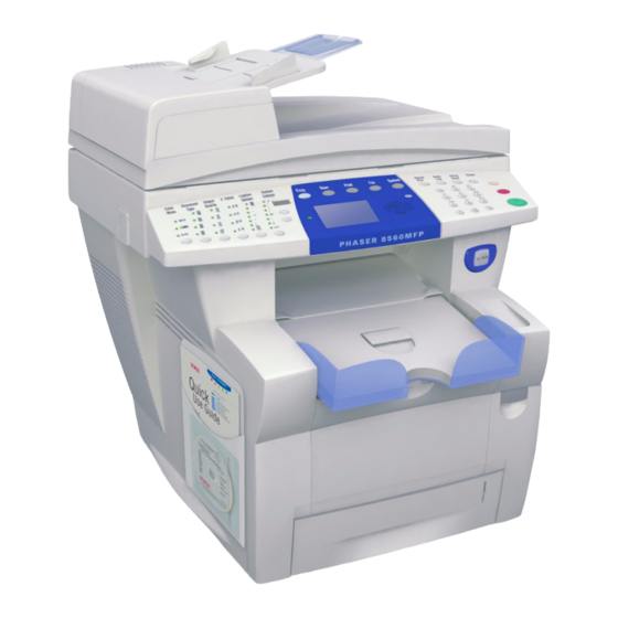
All communications interfaces remain active and have the ability to wake the system up. A signed copy of the Declaration of Conformity for this product can be obtained from Xerox. Figure 1 Phaser 8510/8560MFP Multifunction Product with Optional Trays... -
Page 13: System Configurations
Trays 1 and 2 are standard on all configurations. The following additional tray combinations are Table 1 Phaser 8510/8560MFP Print Speeds supported: Phaser 8510MFP Multifunction Product Phaser 8560MFP Multifunction Product • One 525-Sheet Feeder (Tray 3) PostScript Print Quality Modes: PostScript Print Quality Modes: •... -
Page 14: Parts Of The Product
Parts of the Product Open View Front View Figure 2 Open View Output Tray Figure 1 Front View Short Paper Stop Exit Cover Tray 4 (optional) Ink Loader Cover Tray 3 (optional) Scan Head Lock Tray 2 Tray 1 (MPT) Output Tray Exit Cover Control Panel... - Page 15 Side View with Interface Connections Figure 3 Side View with Interface Connections Drum Maintenance Kit Waste Tray Figure 4 Back View AC Power Cord Connection Power Switch RAM Connectors Scanner Cable Connection NVRAM Device USB Connection Hard Drive Ethernet Connection Printer Stabilizer Configuration Card RJ-11 Fax Modem Connection...
-
Page 16: Control Panel Layout
Routine Maintenance Items Control Panel Layout The Control Panel functions are segregated into three areas. Figure 1 Control Panel Table 1 Control Panel Functional Areas Left Side Center Right Side Copy, Scan, and Fax functions Display, Mode, Navigation but- Numeric keypad, Stop, Start, and indicator LEDs tons, and status LED’s Clear, and Clear All buttons... - Page 17 Yellow indicates a warning condition. The system continues the operation. Password Bypass UP+DOWN • Red indicates a startup or operational error condition. Enter Service Diagnostics BACK+? before the Xerox logo stops scrolling and • Blinking indicates a warm-up or busy condition. until Beginning Service Mode appears. Initial Issue Introduction...
-
Page 18: Specifications
Specifications Physical Dimensions and Clearances Functional Specifications Table 4 Print Engine Dimensions Value Table 1 Functional Specifications Height 620 mm (24.4 in.) Characteristic Specifications Width 530 mm (20.9 in.) Printing Process Four-color (CMYK) solid ink Printhead architecture. Depth 660 mm (26.2 in.) Image System Transfix transfer from oil coated Drum Weight... - Page 19 Print Engine Specifications Table 7 Scanner/DADF Functional Specifications Characteristic Specification Table 6 Print Engine Functional Specifications Noise Standby: < or equal to 45 dB Characteristic Specification Scanning: < or equal to 50 dB Printing process Solid-ink Electrical Specifications Controller 500 MHz processor Color medium Yellow, cyan, magenta, and black ink sticks, each shape- Table 8 Electrical Specifications...
- Page 20 Select Paper Tips, and then press the OK button to print. cause poor output quality, increased jams, or damage. Unacceptable media includes: • Rough, plastic, or porous media See also: Recommended Media List at www.xerox.com/paper • Paper that has been stapled, folded, photocopied, or wrinkled •...
- Page 21 1 Service Call Procedures Service Call Procedures....................Initial Actions ........................Routine Maintenance Activities ..................Cleaning Procedures....................... Final Actions........................Initial Issue Service Call Procedures 10/2006 Phaser 8510/8560MFP Multifunction Product...
- Page 22 Service Call Procedures Initial Issue 10/2006 Phaser 8510/8560MFP Multifunction Product...
- Page 23 Service Call Procedures Accessing Engine Fault History Listed below are three ways in which you can access fault history records. This section describes an overview of the steps a service technician should take, using this manual, to service the system and attached options. The system’s diagnostic routines report Print (if possible) the Status page from the Troubleshooting menu -->...
-
Page 24: Service Call Procedures
Table 1 Service Tools Initial Actions Description Detail Purpose Optional Tools Use the following procedure to determine the reason for the service call and to identify and Canned Air organize the actions which must be performed. 3 -Prong Claw Part-Retriever Procedure Pointer with Magnetized Head Gather the information about the service call and the condition of the copier/printer. -
Page 25: Routine Maintenance Activities
Routine Maintenance Activities Cleaning Procedures Procedure Purpose Clean the Pick Rollers on every call. The purpose is to provide cleaning procedures to be performed at every call. Use the Control Panel to check maintenance item counters. Procedure Compare the counter values to those listed in Table 1. CAUTION Advise the customer of any routine maintenance items that are approaching or over the service limit. -
Page 26: Final Actions
Final Actions Purpose The intent of this procedure is to be used as a guide to follow at the end of every service call. Procedure Check that the exterior of the system and the adjacent area is clean. Use a dry cloth or a cloth moistened with water to clean the exterior of the system. - Page 27 2 Error Messages and Codes Power On Self Tests ....................... 29,0XX.6x Jam Manager Faults ..................2-35 NVRAM Reset ......................... 31,001.40 Mechanical Initialization Jam................2-36 Error Message Troubleshooting..................31,0XX.6x Program Faults ....................2-36 1,00X.4x 525-Sheet Feeder Faults ................. 33,00X.4x Tray 1 Width Sensor Faults................2-37 1,000.6x 525-Sheet Feeder Program Faults..............
-
Page 28: Initial Issue
Error Messages and Codes Initial Issue 10/2006 Phaser 8510/8560MFP Multifunction Product... -
Page 29: Power On Self Tests
For problems associated with an error message or code, see Error Message Control Panel is initialized. Troubleshooting. Troubleshooting tips are available at: www.xerox.com/support. The following table defines the blink patterns associated with a failure: Check the main menu for current data and historical error data. - Page 30 NOTE: Before replacing the Electronics Module for any POST errors, do the following: Table 2 POST Blink Pattern Error Reporting Unplug all wiring and/or cables to the Electronics Module. Error PS, PE, and Control Error Plug in the AC power cable and power on the Electronics Module. Code Panel LED s Type Description...
-
Page 31: Nvram Reset
NVRAM Reset Table 1 Parameters Reset with the Service Diagnostics NVRAM Reset Command Menu Parameter Default Required Many of the troubleshooting procedures in this section include an NVRAM reset as a proce- dural step. Following an NVRAM reset, the system is unable to communicate on the network Copy Main Number of Copies and has lost several parameters specific to the customer’s configuration. - Page 32 Table 1 Parameters Reset with the Service Diagnostics NVRAM Reset Command Table 1 Parameters Reset with the Service Diagnostics NVRAM Reset Command Menu Parameter Default Required Menu Parameter Default Required Fax Send Setup Transmission Report Never System Controls Startup Page Reduced Image (8560 only) Auto Clear Timeout 60 sec.
-
Page 33: Error Message Troubleshooting
Table 2 System Parameters Not Affected by an NVRAM Reset Error Message Troubleshooting Parameter Comment This section covers troubleshooting procedures utilizing Control Panel error messages and codes. Some procedures require running Service Diagnostic test functions to verify that a com- License Number ponent is operating correctly. -
Page 34: 1,00X.4X 525-Sheet Feeder Faults
1,00X.4x 525-Sheet Feeder Faults Table 2 525-Sheet Troubleshooting Procedure Step Questions or Actions The following troubleshooting procedure applies to these errors: Check the wiring from the feeder to Elec- Replace the har- Replace the feeder. 525-Sheet Feeder Errors tronics Module. ness. -
Page 35: 1,000.6X 525-Sheet Feeder Program Faults
1,000.6x 525-Sheet Feeder Program Faults 2,00X.xx I/O Board Errors A firmware error has occurred. The following troubleshooting procedure applies to these errors: The following troubleshooting procedure applies to these errors: 525-Sheet Feeder Program Errors I/O Circuit Board Errors 1,006.x The 525-Sheet Feeder has encountered a program fault. 2,001.47 The Print Engine does not detect the I/O Board Initial Actions... -
Page 36: 2,006.Xx I/O Board Program Faults
2,006.xx I/O Board Program Faults 2,0XX.6x Configuration Card Faults The following troubleshooting procedure applies to these errors: The following troubleshooting procedure applies to these errors: I/O Board Program Faults I/O Board Program Faults 2,001.69 The Electronics Module Failed to initialize. 2,008.67 The Configuration Card is Missing 2,002.61... -
Page 37: 3,0Xx.6X Ipc Program Faults
3,0XX.6x IPC Program Faults 4,0xx.4x Process Control Errors A firmware communications error has occurred. The following troubleshooting procedure The following troubleshooting procedure applies to these errors: applies to these errors: Process Control Errors Initial Actions 4,017.47 The ambient temperature is too low ( < 10°C). •... -
Page 38: 4,024.42 Wiper Alignment Fault
4,024.42 Wiper Alignment Fault 4,025.46 Drum Transfix Fault The following troubleshooting procedure applies to this error: The following troubleshooting procedure applies to this error: Wiper Blade Misalignment Errors Drum Transfix Fault 4,024.42 Printhead Wiper Blade misaligned 4,025.46 Drum Transfix does not reach home position. Initial Actions Initial Actions •... -
Page 39: 4,0Xx.6X Process Control Program Faults
4,0xx.6x Process Control Program Faults 5,0xx.4x Y-Axis Sub-System Faults A firmware communications error has occurred. The following troubleshooting procedure The following troubleshooting procedure applies to these errors: applies to these errors: Y-Axis Sub-System Faults Initial Actions 5,001.41 The Drum rotated once without a Drum Home Position Sensor activation. •... -
Page 40: 5,0Xx.6X Y-Axis Sub-System Program Faults
Table 2 Y-Axis Sub-System Faults Troubleshooting Procedure 5,0xx.6x Y-Axis Sub-System Program Faults Step Questions or Actions A software error has occurred. The following troubleshooting procedure applies to these errors: Test the Y-Axis Motor. Replace the Drum Replace the Y-Axis Y-Axis Sub-System Program Faults Run the Service Diagnostics Y-Axis Motor Assembly (REP Motor (REP 4.0.11). -
Page 41: 6,0Xx.4X X-Axis Fault
6,0xx.4x X-Axis Fault 6,0xx.6x X-Axis Program Faults An X-Axis drive error has occurred. The following troubleshooting procedure applies to this A software error has occurred. The following troubleshooting procedure applies to these errors: error: X-Axis Program Faults X-Axis Motor Error 6,001.64 The X-Axis task received an unexpected message. -
Page 42: 7,002.44 Process Drive Fault
7,002.44 Process Drive Fault 7,006.4x Head Tilt Solenoid Fault A Process Drive error has occurred. The following troubleshooting procedure applies to this A Printhead tilt error has occurred. The following troubleshooting procedure applies to this error: error: Process Faults Process Faults 7,002.44 The Process Drive stalled during operation. -
Page 43: 7,007.49 Process Drive Fault
7,007.49 Process Drive Fault 7,008.41 Printhead Tilt Fault A Process Drive or Printhead error has occurred. The following troubleshooting procedures A Process Drive or Printhead error has occurred. The following troubleshooting procedure applies to this error: applies to this error: Process Drive Fault Process Faults 7,007.49 The Process Drive stalled while tilting the Printhead. -
Page 44: 7,009.42 Printhead Restraint Fault
Table 2 Head Tilt Solenoid Faults 7,008.41 Troubleshooting Procedure 7,009.42 Printhead Restraint Fault Step Questions or Actions A Process Drive or Printhead error has occurred. The following troubleshooting procedure applies to this error: Test the Head Maintenance Clutch. Go to Step 8. Replace the clutch Run the Service Diagnostics Head Main- (REP 4.0.4). -
Page 45: 7,01X.4X Process Faults
Table 2 Printhead Restraint Fault 7,009.42 Troubleshooting Procedure 7,01X.4x Process Faults Step Questions or Actions A Process Drive or Printhead error has occurred. The following troubleshooting procedures apply to these errors: Test the Wiper Drive. Replace the Exit Repair the Wiper Run the Service Diagnostics Wiper Drive Module (REP 3.0.7). -
Page 46: 7,0Xx.6X Program Faults
Table 2 Printhead Restraint Fault 7,010.xx through 7,015.xx Troubleshooting Procedure 7,0xx.6x Program Faults Step Questions or Actions A software error has occurred. The following troubleshooting procedure applies to these errors: Check the X-Axis Motor. Go to Step 5. Check the X-Axis Process Program Faults Does the X-Axis Motor drive the Printhead Drive (6,0xx.4x). -
Page 47: 8,0Xx.4X Wiper Or Media Drive Faults
8,0XX.4x Wiper or Media Drive Faults Table 2 Media Drive Troubleshooting Procedure Step Questions or Actions A software error has occurred. The following troubleshooting procedure applies to these errors: For an 8,009.43 error: Complete. Replace the Media Wiper or Media Drive Faults Check for paper in the paper path. -
Page 48: 8,0Xx.6X Media Drive Program Faults
Does the problem persist? Check ground integrity. Reset NVRAM. If the Reconnect the sys- • Check that the Ink Sticks are genuine Xerox. Are the system grounds connected? error persists, tem grounds. • Check for obstructions in the Ink Wells. -
Page 49: 9,009.44 And 9,00X.6X Ink Loader Program Faults
Troubleshooting Procedure 9,009.44 and 9,00X.6x Ink Loader Program Faults A software error has occurred. The following troubleshooting procedure applies to these errors: Table 2 Process Drive Faults 9,0XX.4x Troubleshooting Procedure Step Questions or Actions Ink Loader Program Faults 9,009.44 Communications error in NVRAM. Check that the ink stick is able to advance Go to Step 2. -
Page 50: 11,0Xx.xx Electronics Module Interface Faults
11,0XX.xx Electronics Module Interface Faults Troubleshooting Procedure A communications error has occurred. The following troubleshooting procedure applies to Table 2 Process Drive Faults 11,0xx.4x Troubleshooting Procedure these errors: Step Questions or Actions Ink Loader Faults Check ground integrity for the printer. Go to Step 2. -
Page 51: 11,100.60 Electronics Module Temperature Fault
11,100.60 Electronics Module Temperature Fault 12,000.60 Program Faults The root problem for this error is temperature sensitivity with the power supply’s opto-isolator A software error has occurred. The following troubleshooting procedure applies to these errors: chips. The following troubleshooting procedure applies to this error: Program Faults Program Faults 12,000.60... -
Page 52: 13,000.48 Printhead Thermal Fault
13,000.48 Printhead Thermal Fault 13,003.42 and 13,007.46 Thermal Faults A thermal error is detected in the Printhead. The following troubleshooting procedure applies to A thermal error has occurred. The following troubleshooting procedures apply to these errors: this error: Thermal Faults Process Thermal Faults 13,003.42 Thermal fault 13,000.48 A thermal fault was detected in the Printhead. -
Page 53: 13,008.47 And 13,010.49 Drum Thermal Faults
13,008.47 and 13,010.49 Drum Thermal Faults Table 2 13,008.47 and 13,010.49 Troubleshooting Procedure Step Questions or Actions A Drum Assembly thermal error has occurred. The following troubleshooting procedures apply to these errors: Test the Drum Temperature Sensor. Go to Step 8. Replace the Drum Run the Service Diagnostics Drum Tem- Temperature Sen-... -
Page 54: 13,Xxx.4X Preheater Thermal Faults
13,067.43, 13,069.45, 13,071.47 Drum Temp Sensor Faults 13,XXX.4x Preheater Thermal Faults A Drum Temperature Sensor error has occurred. The following troubleshooting procedures A Preheater thermal error has occurred. The following troubleshooting procedures apply to apply to these errors: these errors: Drum Temperature Sensor Faults Preheater Thermal Faults 13,067.43 The Drum Thermistor circuit is open. -
Page 55: 13,1Xx.4X Left Jetstack Thermal Faults
13,1XX.4x Left Jetstack Thermal Faults 13,2XX.4x Right Jetstack Thermal Faults A thermal error in the Printhead jetstack has occurred. The following troubleshooting proce- A thermal error in the Printhead jetstack has occurred. The following troubleshooting proce- dures apply to these errors: dures apply to these errors: Left Jetstack Thermal Faults Right Jetstack Thermal Faults... -
Page 56: 13,Xxx.xx Printhead Reservoir Thermal Faults
13,XXX.xx Printhead Reservoir Thermal Faults 13,XXX.xx Ink Loader Thermal Faults A Printhead Reservoir thermal error has occurred. The following troubleshooting procedures A thermal error has occurred. The following troubleshooting procedures apply to these errors: apply to these errors: Ink Loader Thermal Faults Printhead Reservoir Thermal Faults 13,328.43 The Cyan heater is too hot. -
Page 57: 13,00X.6X Thermal Program Faults
Troubleshooting Procedures 13,00x.6x Thermal Program Faults A software error has occurred. The following troubleshooting procedure applies to these errors: Table 2 Ink Loader Ink Melt Heater 13,328.43 through 13,581.44 Procedure Step Questions or Actions X-Axis Program Faults 13,001.62 Thermals failed to read system NVRAM. Verify that the ambient temperature of the Go to Step 2. -
Page 58: 19,0Xx.4X Printhead Calibration Faults
19,0XX.4x Printhead Calibration Faults 19,0XX.6x Waveform Program Faults The root problem for this error is temperature sensitivity with the power supply’s opto-isolator A software error has occurred. The following troubleshooting procedure applies to these errors: chips. The following troubleshooting procedure applies to this error: X-Axis Program Faults Printhead Calibration Faults 19,001.68... -
Page 59: 21,000.69 Diagnostic Firmware Version Mismatch
21,000.69 Diagnostic Firmware Version Mismatch 22,0XX.6x Jam Fault A software error has occurred. The following troubleshooting procedure applies to these errors: A jam has occurred. The system generates a four-digit, alphanumeric code associated to a particular area of the paper path, followed by the value of the system page counter when the X-Axis Program Faults jam occurred <jam code><page count>. -
Page 60: 23,0Xx.6X Nvram Faults
23,0XX.6x NVRAM Faults 26,0XX.6x Printing Faults An NVRAM error has occurred. The following troubleshooting procedure applies to these A printing process error has occurred. The following troubleshooting procedure applies to errors: these errors: NVRAM Faults Printing Faults 23,0xx.6x The system detected an NVRAM fault during operation. 26,0xx.6x A printing process fault occurred during operation. -
Page 61: 27,0Xx.6X Profile Library
27,0XX.6x Profile Library 29,0XX.6x Jam Manager Faults A profile library error has occurred. The following troubleshooting procedure applies to these A software error has occurred. The following troubleshooting procedure applies to these errors: errors: Jam Manager Faults Profile Library Faults 29,0XX.6x Jam Manager program faults. -
Page 62: 31,001.40 Mechanical Initialization Jam
31,001.40 Mechanical Initialization Jam 31,0XX.6x Program Faults A software error has occurred. The following troubleshooting procedure applies to this error: A software error has occurred. The following troubleshooting procedure applies to these errors: Mechanical Initialization Fault Program Faults 31,001.40 Mechanical initialization jam fault. 31,0XX.6x Program faults. -
Page 63: 33,00X.4X Tray 1 Width Sensor Faults
33,00X.4x Tray 1 Width Sensor Faults 34,00X.4x Printhead NVRAM Faults The Paper Width Sensor, located in the Tray 1/Front Door Assembly is reporting out of range The Printhead is unable to access system NVRAM. The following troubleshooting procedure values. The following troubleshooting procedure applies to these errors: applies to these errors: Tray Manager Device Faults Printhead NVRAM Faults... -
Page 64: 36,000.40 Drum Maintenance Faults
36,000.40 Drum Maintenance Faults 36,001.67 Drum Maintenance Drive Faults An error occurred while attempting to position the Drum Maintenance Kit. The following trou- An error occurred while attempting to position the Drum Maintenance Kit. The following trou- bleshooting procedure applies to these errors: bleshooting procedure applies to this error: Printhead NVRAM Faults Drum Maintenance Drive Faults... -
Page 65: 36,002.44 Drum Maintenance Kit Fault
36,002.44 Drum Maintenance Kit Fault 37,0XX.xx PEST Heater Faults An error occurred while attempting to position the Drum Maintenance Kit. The following trou- An heating error has occurred. The following troubleshooting procedure applies to these errors: bleshooting procedure applies to this error: PEST Heater Faults Drum Maintenance Drive Faults 37,001.46 An error occurred during PEST execution. -
Page 66: 37,01X.41 Pest Fan Faults
37,01X.41 PEST Fan Faults 37,016.43 PEST 50 Volt Supply Fault An fan error has occurred. The following troubleshooting procedure applies to these errors: An error has occurred related to the Electronics Module 50 V Power Supply. The clutches oper- ate at 50 V. The Head Maintenance, Deskew, and Pick clutches are drawing too much power PEST Heater Faults indicating a short in the supply or one of the components connected to it. -
Page 67: 37,0Xx.4X Pest Clutch/Solenoid Faults
Table 2 PEST 50 V Supply Fault 37,016.43 Troubleshooting Procedure 37,0XX.4x PEST Clutch/Solenoid Faults Step Questions or Actions An heating error has occurred. The following troubleshooting procedure applies to these errors: Shutdown the system and wait 30 sec- Go to Step 4. Go to Step 5. -
Page 68: 37,024.48 Pest Tray 2 Lift Motor Fault
37,024.48 PEST Tray 2 Lift Motor Fault 37,026.44 PEST Purge Pump Fault An error has occurred related to the Tray 2 Lift Motor. The following troubleshooting procedure An error has occurred related to the Purge Pump. The following troubleshooting procedure applies to this error:. -
Page 69: 37,02X.4X Pest Relay Board Faults
37,02X.4x PEST Relay Board Faults 37,03X.4x PEST X-Axis Motor Faults An Relay Board error has occurred. The following troubleshooting procedure applies to these An X-Axis Motor error has occurred. The following troubleshooting procedure applies to these errors: errors: PEST Relay Board Faults PEST X-Axis Motor Faults 37,027.45 Both relay coils are drawing less power than expected. -
Page 70: 37,035.44 And 37,036.45 Pest Y-Axis Motor Faults
37,035.44 and 37,036.45 PEST Y-Axis Motor Faults 37,037.46 and 37,038.47 PEST Media Drive Faults A Y-Axis Motor error has occurred. The following troubleshooting procedure applies to these A Media Drive Assembly error has occurred. The following troubleshooting procedure applies errors: to these errors: PEST Y-Axis Motor Faults PEST Media Drive Faults... -
Page 71: 37,039.48 And 37,040.40 Pest Process Drive Faults
37,039.48 and 37,040.40 PEST Process Drive Faults 37,0XX.4x PEST Power Supply Faults A Y-Axis Motor error has occurred. The following troubleshooting procedure applies to these An Power Supply error has occurred. The following troubleshooting procedure applies to these errors: errors: PEST Process Drive Faults PEST Power Supply Faults 37,039.48 The Process Drive Motor is drawing less power than expected. -
Page 72: 39,002.40 And 39,003.41 Scanner Subsystem Test Faults
Troubleshooting Procedure 39,002.40 and 39,003.41 Scanner Subsystem Test Faults A Scanner DRAM or Optical self test error has occurred. The following troubleshooting proce- Table 2 PEST Power Supply Faults 37,0XX.4x Troubleshooting Procedure dure applies to these errors: Step Questions or Actions Scanner Subsystem Test Faults Test the Power Supply. -
Page 73: 39,004.42 Scanhead Locked Or Shipping Restraint Faults
39,004.42 Scanhead Locked or Shipping Restraint Faults 39,005.43 Scanner Missing Fault A Scanner self test determined the Scanhead was either locked, or the shipping restraint A Scanner was not detected. The following troubleshooting procedure applies to these errors: remained. The following troubleshooting procedure applies to these errors: Scanner Missing Fault Scanhead Lock or Shipping Restraint Faults 39,005.43 The system did not detect the Scanner Assembly. -
Page 74: 39,010.8 Document Feeder Disconnected Or Missing
Table 2 Scanhead Missing Troubleshooting Procedure 39,010.8 Document Feeder Disconnected or Missing Step Questions or Actions The system could not detect the DADF. The following troubleshooting procedure applies to this error: Is the Status LED Off? Replace the Scanner Go to Step 6. Power Supply (REP Document Feeder Disconnected or Missing Faults 5.0.2). -
Page 75: 39,011.40 And 39,012.40 Dadf Subsystem Test Faults
39,011.40 and 39,012.40 DADF Subsystem Test Faults 39,013.42 Document Feeder Jam The DADF DRAM or Optical self test error has occurred. The following troubleshooting proce- A media Jam is detected in the DADF. The following troubleshooting procedure applies to this dure applies to these errors: error: DADF Subsystem Faults... -
Page 76: 39,014.43 Document Feeder Calibration Fault
39,014.43 Document Feeder Calibration Fault Jam Codes A calibration faults is detected in the DADF. The following troubleshooting procedure applies to The printer stores the most recent 20 events in Jam History. To access this information for this error: Phaser 8510/8560MFP systems, press and hold the Up Arrow button, then scroll to Jam His- tory and press OK to display the most recent jam list. - Page 77 Table 2 Jam Code Troubleshooting Table 2 Jam Code Troubleshooting Code Description / Procedure Code Description / Procedure Deskew sensor in unexpected state. Deskew sensor time-out during movement from exit roller to deskew roller when Check system grounding. duplexing print. Ensure the media is appropriate for two-sided printing.
- Page 78 Table 2 Jam Code Troubleshooting Table 2 Jam Code Troubleshooting Code Description / Procedure Code Description / Procedure Strip flag unexpected event during mechanical recovery. Print pulled back into transfix nip during exit. Strip flag unexpected state during warm-up. Check that the media is not too thick and is supported by the system. Strip flag unexpected event during system ready.
- Page 79 Table 2 Jam Code Troubleshooting Table 2 Jam Code Troubleshooting Code Description / Procedure Code Description / Procedure Tray 1 width sensor during warm-up. Media Drive motor had an unexpected event during mechanical recovery. Tray 1 width sensor during operation. Media Drive motor stalled during an abnormal printer shutdown.
- Page 80 Table 2 Jam Code Troubleshooting Table 2 Jam Code Troubleshooting Code Description / Procedure Code Description / Procedure Y-Axis motor stalled on power-up following an abnormal shutdown. Y-Axis Motor media long during transfix. The media was longer than expected. Y-Axis motor stalled on power-up following a normal shutdown. Check for supported media.
- Page 81 Table 2 Jam Code Troubleshooting Table 2 Jam Code Troubleshooting Code Description / Procedure Code Description / Procedure Exit Door Interlock tripped following an abnormal shutdown. Tray 3 Paper Size Switch activated during warm-up. Exit Door Interlock tripped following a normal shutdown. Tray 3 Paper Size Switch activated during ready state.
- Page 82 Table 2 Jam Code Troubleshooting Table 2 Jam Code Troubleshooting Code Description / Procedure Code Description / Procedure Tray 3 pick flag timed-out during warm-up. Tray 4 pick flag actuated during an abnormal shutdown. Tray 3 pick flag timed-out during ready state. Tray 4 pick flag actuated during a normal shutdown.
- Page 83 3 Image Quality IQ1 IOT Image Quality Entry RAP .................. IQ2 Dark Streaks on Copied Image ................IQ3 Voids in the Copied Image ..................IQ4 Skewed Copy Image ....................IQ6 Fuzzy Text or Image....................IQ5 Copy Image is Lighter or Darker than the Original ........... IQ7 Copied Image Colors Do Not Match the Original .............
- Page 84 Image Quality Initial Issue 10/2006 Phaser 8510/8560MFP Multifunction Product...
-
Page 85: Iq1 Iot Image Quality Entry Rap
IQ1 IOT Image Quality Entry RAP Table 2 Scanner Image Quality Problems Symptom The purpose of this RAP is to establish the source of the imaging defect. After following the Ini- tial Actions, select the RAP that best describes the observed defect. Fuzzy Text or Image IQ12 Initial Actions... -
Page 86: Iq2 Dark Streaks On Copied Image
IQ2 Dark Streaks on Copied Image IQ3 Voids in the Copied Image This RAP addresses image quality problems associated with the DADF. This RAP addresses image quality problems associated with the DADF. Initial Actions Initial Actions Check that supported media is being used. Check that supported media is being used. -
Page 87: Iq4 Skewed Copy Image
IQ4 Skewed Copy Image IQ6 Fuzzy Text or Image This RAP addresses image quality problems associated with the DADF. See the Skew and This RAP addresses image quality problems associated with the DADF. Margins test print discussion. Initial Actions Initial Actions Check that supported media is being used. -
Page 88: Iq5 Copy Image Is Lighter Or Darker Than The Original
IQ5 Copy Image is Lighter or Darker than the Original IQ7 Copied Image Colors Do Not Match the Original This RAP addresses image quality problems associated with the DADF. This RAP addresses image quality problems associated with the DADF. Initial Actions Initial Actions Check that supported media is being used. -
Page 89: Iq8 Dark Streaks On Copied Image
IQ8 Dark Streaks on Copied Image IQ9 Copy Image is Skewed This RAP addresses image quality problems associated with the Scanner Assembly. This RAP addresses image quality problems associated with the Scanner Assembly. Initial Actions Initial Actions Check that supported media is being used. Check that supported media is being used. -
Page 90: Iq10 Copy Image Is Lighter Or Darker Than The Original
IQ10 Copy Image is Lighter or Darker than the Original IQ11 Copied Image Colors Do Not Match the Original This RAP addresses image quality problems associated with the DADF. This RAP addresses image quality problems associated with the DADF. Initial Actions Initial Actions Check that supported media is being used. -
Page 91: Iq12 Fuzzy Text Or Image
IQ12 Fuzzy Text or Image IQ13 Random Light Stripes This RAP addresses image quality problems associated with the DADF. This RAP addresses image quality problems associated with the Print Engine. Random light stripes typically result from an obstructed Printhead jet. Indications of a random light stripe Initial Actions condition are one or more color bars missing on the test page, or output that appears as fol- lows:... -
Page 92: Iq14 Predominate Light Stripes
Initial Actions IQ14 Predominate Light Stripes Check that supported media is being used. This RAP addresses image quality problems associated with the Print Engine. Predominate Run the Eliminate Light Stripes routine from the Control Panel. light stripes typically result from something scraping the image off the Drum before Transfixing. Indications of a random light stripe condition are all four color bars missing on the test page, or output that appears as follows: Procedure... -
Page 93: Iq15 Smudges Or Smears
IQ15 Smudges or Smears IQ16 Printed Image is Too Light or Too Dark This RAP addresses image quality problems associated with the Print Engine. Smudges or This RAP addresses image quality problems associated with the Print Engine. smears typically result from ink residue in the paper path. Residue can collect on the rollers, Initial Actions paper guide ribs, or inside the Preheater. -
Page 94: Iq17 No Image Is Printed
Figure 1 Example of Uneven or Incorrect Color Output Does the problem persist? problem persists, replace the Print- NOTE: Using non-Xerox ink may cause unpredictable color results. head (REP 2.0.2). Initial Actions Check that supported media is being used. Run the Eliminate Light Stripes routine from the Control Panel. -
Page 95: Iq19 Streaks Or Lines Down The Print
Table 1 IQ18 Color is Uneven or Color is Wrong IQ19 Streaks or Lines Down the Print Step Questions and Actions This RAP addresses image quality problems associated with the Print Engine. Streaking or lines typically result from parts in contact with the Drum, dirty Wiper Blade, or debris in the Check thermal regulation of the Drum. - Page 96 Table 1 IQ19 Streaks or Lines Down the Print IQ20 Scratches or Marks Parallel to the Long Axis of Printing Step Questions and Actions If streaking or lines occur on only one side of Go to Step 5. Complete. This RAP addresses image quality problems associated with the Print Engine. Scratches or a 2-sided print, the Preheater may be scrap- marks typically result from debris in the paper path.
-
Page 97: Iq21 Ink On The White Portion Of The Printed Page
Table 1 IQ20 Scratches or Marks Parallel to the Long Axis of Printing IQ21 Ink on the White Portion of the Printed Page Step Questions and Actions This RAP addresses image quality problems associated with the Print Engine. Color appearing on blank areas of the output is called latent image. -
Page 98: Iq22 Fuzzy Text
Table 1 IQ21 Ink on the White Portion of the Printed Page IQ22 Fuzzy Text Step Questions and Actions This RAP addresses image quality problems associated with the Print Engine. Fuzzy text typi- cally results from one of the three causes illustrated. An error in Y-Axis Drum rotation results in Check the thermal regulation of the Drum. -
Page 99: Iq23 Poor Primary Color Fill
Table 1 IQ22 Fuzzy Text IQ23 Poor Primary Color Fill Step Questions and Actions This RAP addresses image quality problems associated with the Print Engine. Poor primary color fills typically result from obstructed jets. X-Axis errors may also cause banding. Indica- Use a higher quality print mode. -
Page 100: Iq24 Ghosting
Table 1 IQ23 Poor Primary Color Fill IQ24 Ghosting Step Questions and Actions This RAP addresses image quality problems associated with the Print Engine. Ghosting typi- cally results from stacked prints, faulty or expended Drum Maintenance Kit, or Drum thermal If banding is uniform, or in a corduroy pattern, Replace the X-Axis Complete. -
Page 101: Iq25 Poor Small Text Resolution
Table 1 IQ24 Ghosting IQ25 Poor Small Text Resolution Step Questions and Actions This RAP addresses image quality problems associated with the Print Engine. Poor text resolu- tion typically results from Drum thermal regulation, or X-Axis drive problems. Poor text resolu- Check and clean the Drum Maintenance Kit Go to Step 4. -
Page 102: Iq26 Vertical Lines Appear Wavy
IQ26 Vertical Lines Appear Wavy IQ27 Oil Streaks on Print This RAP addresses image quality problems associated with the Print Engine. Wavy or ill- This RAP addresses image quality problems associated with the Print Engine. Oil streaking formed vertical lines typically result from excessive Drum oiling. An error in X-Axis or Y-Axis typically results from excessive Drum oiling. -
Page 103: Iq28 Incomplete Image Transfer
Table 1 IQ27 Oil Streaks on Print IQ28 Incomplete Image Transfer Step Questions and Actions This RAP addresses image quality problems associated with the Print Engine. Incomplete image transfer typically results from coarse, underweight, or watermarked media. Incomplete Check that the Drum Maintenance Cam Replace any Complete. -
Page 104: Iq29 Ink Smears On First Side Of Duplex Print
Table 1 IQ28 Incomplete Image Transfer IQ29 Ink Smears on First Side of Duplex Print Step Questions and Actions This RAP addresses image quality problems associated with the Print Engine. Ink smearing typically results from dirt or debris in the paper path, or the Preheater operating at too high a Is the image incomplete of only the sides of Go to Step 6. -
Page 105: Iq30 Repeating Print Defects
IQ30 Repeating Print Defects IQ31 White Stripes (Pinstripes) This RAP addresses image quality problems associated with the Print Engine. Repeating This RAP addresses image quality problems associated with the Print Engine. White striping defects typically result from dirt, debris, or damage to an imaging component. The interval appears as a series of evenly-spaced pinstripes approximately 6 mm (.25 in.) apart. -
Page 106: Iq32 Wrinkling
IQ32 Wrinkling IQ33 Image is Offset or Cut-Off This RAP addresses image quality problems associated with the Print Engine. Wrinkling gen- This RAP addresses image quality problems associated with the Print Engine. Image off-set erally appears in areas of solid fill near the image edge. This problem is more often seen on generally appears as a result of a mismatch between the application and the driver. -
Page 107: Iq34 Poor Ink Adhesion, Poor Image Durability
Turn the system off for 4 to 6 hours (or overnight, if practical). Then perform a clean/purge cycle again. There may be a problem in the purge pump assembly or the wiper assembly may not be compliant. Verify that the printer is using Xerox ink. Follow the instructions on the “Printhead Troubleshooting Checklist”. - Page 108 For X-Axis Motion problems, see solid fill test prints. This print is used by Engineering and The print indicates if the printhead is producing properly-sized drops of ink and that the drum Manufacturing. The print must be printed on Xerox Photo Paper. Using a lower grade paper temperature is not too high.
- Page 109 If there is ink on the top and bottom margin of the page or ink on the back of the page, it may be caused by the roller remaining down during the print. You may hear an unusual noise if the Transfix Roller stays down and rubs against the drum.
- Page 110 Lines: The horizontal lines of the print are made up of long and short dashes. Inspect the first and last 1/2 in. (12 mm) of the black lines for the vertical distance between the short dashes and long dashes. A difference indicates the printhead gaps at each end of the printhead are not equal.
- Page 111 Transfix Roller defects do not move in the X-direction, but these defects repeat every 4.58 in. (11.63 cm) down the length of the page. Many Transfix Roller defects are the most visible on duplex solid fills. Skew and Margins This print is used to gauge skew and margin on 2-sided prints. For Skew: •...
- Page 112 Figure 10 Skew and Margin Measurement Figure 11 Cleaning Page Banding This print is used by Manufacturing. Head Roll This print is used by Manufacturing. Head Height This print is used by Manufacturing. X Dot Position This print is used by Manufacturing and Engineering. Y Dot Position This print is used by Manufacturing and Engineering.
-
Page 113: Jet Substitution Mode
Jet Substitution Mode Enabling Jet Substitution Mode To correct print-quality problems, refer to the Eliminate Light Stripes test page to determine Jet Substitution Mode provides a solution for print-quality problems when weak or missing jets which jets are weak or missing. To access Jet Substitution Mode from the Control Panel: are not recoverable by cleaning. - Page 114 Image Quality Initial Issue 10/2006 Jet Substitution Mode 3-32 Phaser 8510/8560MFP Multifunction Product...
- Page 115 4 Repairs and Adjustments Disassembly Overview ....................REP 4.0.11 Y-Axis Motor Assembly................4-49 REP 1.0.1 Front Door / Tray 1 Assembly................ REP 4.0.12 Tray 1 Pick Solenoid ..................4-51 REP 1.0.6 Output Tray....................REP 4.0.13 Tray 2 Lift Motor................... 4-51 REP 1.0.7 Left Side Cover ....................
- Page 116 Repairs and Adjustments Initial Issue 10/2006 Phaser 8510/8560MFP Multifunction Product...
-
Page 117: Disassembly Overview
Disassembly Overview NOTE: Names of parts that appear in the removal and replacement procedures may not match the names that appear in the Parts List. For example, a part called the Registration Chute This section contains the removal procedures for field-replaceable parts of the system listed in Assembly in a removal procedure may appear on the Parts List as Assembly, Chute REGI. -
Page 118: Rep 1.0.1 Front Door / Tray 1 Assembly
Recommended Tool Kit REP 1.0.1 Front Door / Tray 1 Assembly Table 1 lists basic, recommended, and optional tools used to service this and other similar Parts List on PL 1.0 products. Removal Open the Front Door and release the 2 Stopper Straps. Table 1 Recommended Service Tools Description Detail... -
Page 119: Rep 1.0.6 Output Tray
REP 1.0.6 Output Tray Parts List on PL 1.0 Removal Open the Front Cover. Figure 2 Removing the Output Tray Figure 1 Output Paper Tray Retaining Tabs Spread the left and right sides of the Output Tray to release the 2 tabs on the bottom. Initial Issue Repairs and Adjustments 10/2006... -
Page 120: Rep 1.0.7 Left Side Cover
REP 1.0.7 Left Side Cover REP 1.0.8 Scanner Hinges Parts List on PL 1.0 Parts List on PL 1.0 Removal Removal Open the Front Door. CAUTION Remove the Output Tray (REP 1.0.6). If possible, lock the Scanhead before removing the assembly. A utility for locking the Scanhead is provided in the Service Tools Menu. -
Page 121: Rep 1.0.9 Control Panel
REP 1.0.9 Control Panel Parts List on PL 1.0 Removal Open the Scanner Assembly. Remove 2 (plastic, T-20) screws that secure the Control Panel to the Scanner Assembly. Figure 2 Removing the Scanner Hinges Figure 1 Removing the Control Panel Release the tab at each end of the Control Panel, then release the remaining 4 tabs along the front edge to access the Control Panel connector. -
Page 122: Rep 1.0.11 Scanner Assembly
REP 1.0.11 Scanner Assembly REP 1.0.13 DADF Front Cover Parts List on PL 1.0 Parts List on PL 1.0 Removal Removal CAUTION Open the DADF Front Cover. Lock the Scanhead before removing the assembly. A utility for locking the Scanhead is pro- Remove 3 (plastic, T-20) screws that secure the DADF Front Cover. -
Page 123: Rep 1.0.15 Duplex Automatic Document Feeder
REP 1.0.15 Duplex Automatic Document Feeder Parts List on PL 1.0 Removal Disconnect the DADF Cable from the Scanner Assembly. Lift the DADF to expose the locking mechanism. Release the hinge locks to remove the DADF from the Scanner Assembly. NOTE: If a replacement DADF is being installed, recalibrate the Scanner using ADJ 1.15.1. -
Page 124: Rep 1.0.19 Duplex Automatic Document Feeder Hinges
REP 1.0.19 Duplex Automatic Document Feeder Hinges REP 1.0.20 Rear Cover Parts List on PL 1.0 Parts List on PL 1.0 Removal Removal Remove the DADF (REP 1.0.11). Remove the Right Side Cover (REP 1.0.21). Remove the 4 (plastic, T-20) screws that secure each hinge to the DADF. Remove the Left Side Cover (REP 1.0.7). -
Page 125: Rep 1.0.21 Right Side Cover
REP 1.0.21 Right Side Cover REP 1.0.28 Document Cover Parts List on PL 1.0 Parts List on PL 1.0 Removal Removal Remove the Scanner Assembly with attached DADF (REP 1.0.11). Lift the Document Cover to expose the locking mechanism. Open the Front Door. Release the hinge locks to remove the cover from the Scanner Assembly. -
Page 126: Rep 1.0.29 Document Cover Hinges
REP 1.0.29 Document Cover Hinges REP 2.0.1 Ink Loader Assembly Parts List on PL 1.0 Parts List on PL 2.0 Removal Removal Remove the Document Cover (REP 1.0.28). CAUTION Remove the 4 (plastic, T-20) screws that secure each hinge to the cover. Allow adequate time for the Ink Melters to cool before servicing the Ink Loader. - Page 127 Secure the Ink Loader harness in the retainer clip provided on the Ink Loader, and con- nect P/J0150. Route the Ink Loader Power harness towards the left side and connect P/J5. Transfer the Ink Sticks to the replacement Ink Loader. Figure 2 Removing the Ink Loader Disconnect the Ink Loader Power harness P/J5 from the Electronics Module.
-
Page 128: Rep 2.0.2 Printhead Assembly
REP 2.0.2 Printhead Assembly Parts List on PL 2.0 Removal NOTE: Use the Printhead Troubleshooting Checklist to troubleshoot Printhead operation before replacement. A copy of this checklist is included with the replacement part. Return the completed checklist with the defective part if Printhead replacement is necessary. When parked, the Printhead is held in place by pins that are captured by left and right Print- head Restraints. - Page 129 Figure 3 Releasing the Printhead Tilt Spring. 10. Pull the X-Axis Bias Spring and Hook out slightly, and then rotate downward to allow it to rest in detents provided on the frame. See Figure 4. Figure 2 Lowering the Printhead Wiper Assembly Move the Printhead Tilt Spring from its position on the Printhead and hook it behind itself as shown in Figure 3.
- Page 130 Figure 5 Removing the Printhead Restraint Screws NOTE: Adjust the Printhead along its X-Axis as needed using a small screwdriver inserted in the slot on the X-Axis Motor to allow removal of the Printhead Restraints. Figure 4 X-Axis Bias Spring Hook 11.
- Page 131 Figure 7 Removing the Roll Block Figure 8 Printhead Electrical Connections NOTE: The check mark on the label indicates the proper orientation of the Roll Block. 15. Remove the 2 (metal, T-20) screws that secure the Ground Strap. 16. Push the Air Hose into the chassis. 14.
- Page 132 18. Disconnect the remaining 2 ribbon cables P/J180 and P/J240 from the Printhead. Figure 11 Lifting the Printhead Replacement Figure 10 Printhead Cable Connections Follow these steps to install the replacement Printhead. Ensure the Head Tilt Gear is at its home position by performing ADJ 4.13.1. 19.
-
Page 133: Rep 2.0.3 Drum Assembly
12. Install the Ink Loader. REP 2.0.3 Drum Assembly 13. Perform ADJ 4.13.1 to home the Head Tilt Gear. Parts List on PL 2.0 14. Reassemble the remaining components, and turn system power on. Removal 15. Print the Light Stripes page. Check for jets in Service mode. If necessary, use the Control Remove the Scanner Assembly with attached DADF (REP 1.0.11). - Page 134 15. Unplug the Drum Heater Harness P/J200 from the Relay Board and free the harness from the retaining hook. Figure 2 Disconnecting the Drum 16. Disconnect the Drum Encoder harness P/J120 from the Right Side Harness and release the cable from the restraint. Figure 3 Removing the Drum Assembly 17.
- Page 135 Install 1 (metal, hex-head) screw and washer at the rear position on the right-side to hold the Drum Assembly and torque the screw to 25 in.-lbs. Install the remaining (metal, hex-head) screws into the bottom location (without a washer) and the front location (with a washer and Ground Plate) on the right side of the Drum Assembly and torque to 25 in.-lbs.
- Page 136 Figure 6 Attaching the Transfix Load Module Arm Cam Springs Figure 5 Exit Module Left Side Fasteners 16. Pull the lower end of the Y-Axis Spring Arm toward the front of the system and install the Y-Axis Belt first on the motor pulley, and then on the drum pulley. Align the grooves of the 14.
-
Page 137: Rep 2.0.4 Y-Axis Belt
31. Install the Inner Simplex Guide. REP 2.0.4 Y-Axis Belt 32. Install all covers, doors, and the Output Tray. Parts List on PL 2.0 33. Install the Scanner and DADF. Removal 34. Perform the Wiper Alignment Adjustment (ADJ 2.5.1). Remove the Left Side Cover (REP 1.0.7). 35. -
Page 138: Rep 2.0.5 Printhead Wiper Blade And Wiper Belt
REP 2.0.5 Printhead Wiper Blade and Wiper Belt Hold the Wiper Blade while rotating the small drive gear. This lowers the left end of the wiper producing slack in the Wiper Belt. Remove the Wiper Belt from the Wiper Clip to Parts List on PL 2.0 release the Wiper Blade. -
Page 139: Rep 2.0.7 Purge Pressure Pump
REP 2.0.7 Purge Pressure Pump REP 2.0.8 Left and Right Printhead Restraints Parts List on PL 2.0 Parts List on PL 2.0 Removal Removal Remove the Left Side Cover (REP 1.0.7). When parked, the Printhead is held in place by pins that are captured by left and right Print- head restraints. - Page 140 Figure 3 Releasing the Printhead Tilt Spring. 10. Pull the X-Axis Bias Spring and Hook out slightly, and then rotate downward to allow it to rest in detents provided on the frame. See Figure 4. Figure 2 Lowering the Printhead Wiper Blade Hold the Printhead away from the Drum and push down on the left and right Printhead Restraint Arms to release the Printhead Tilt Spring tension.
- Page 141 Figure 5 Removing the Printhead Restraint Screws NOTE: Use a flat-bladed screwdriver to rotate the X-Axis Motor to adjust the Printhead position as needed to remove the Printhead Restraints. Figure 4 X-Axis Bias Spring Hook 11. Disconnect the Air Hose from the Purge Pump. 12.
-
Page 142: Rep 2.0.10 Transfix Camshaft
Replacement REP 2.0.10 Transfix Camshaft Check that the Left Printhead Restraint does not interfere with the Roll Block. Also, make sure Parts List on PL 2.0 the Tilt Spring on the Left Printhead Restraint is properly positioned in the notch on the back of Removal the Printhead and does not pinch the Air Hose. -
Page 143: Rep 2.0.11 Drum Maintenance Camshaft
REP 2.0.11 Drum Maintenance Camshaft Parts List on PL 2.0 Removal Remove the Drum Maintenance Pivot Plate (REP 2.0.16). Remove the Process Drive (REP 4.0.7). Slide the camshaft to the right, release the bushing by carefully prying it from the ground plate, Move the left end of the camshaft towards the rear of the printer move the camshaft to the right, then lift the camshaft through the slot while removing it to the right. -
Page 144: Rep 2.0.12 Stripper Carriage Assembly
REP 2.0.12 Stripper Carriage Assembly 10. Hold the Transfix Roller and Stripper Blade with one hand, engage the end of the Transfix Roller Shaft with the Transfix Roller Shaft Restraint and pull the shaft out of the Stripper Parts List on PL 2.0 Carriage Assembly. -
Page 145: Rep 2.0.13 Transfix Roller
REP 2.0.13 Transfix Roller 10. Hold the Transfix Roller and Stripper Blade with one hand, engage the end of the Transfix Roller Shaft with the Transfix Roller Shaft Restraint and pull the shaft out of the Stripper Parts List on PL 2.0 Carriage Assembly. -
Page 146: Rep 2.0.14 Y-Axis Spring
REP 2.0.14 Y-Axis Spring REP 2.0.15 Transfix Load Module Parts List on PL 2.0 Parts List on PL 2.0 Removal Removal Remove the Scanner Assembly and Attached DADF (REP 1.0.11). Remove the Scanner Assembly and attached DADF (REP 1.0.11). Remove the Output Tray (REP 1.0.6). Remove the Front Door (REP 1.0.1). - Page 147 Figure 3 Removing the Preheater Lift Solenoid 14. Remove the screw that secures the Transfix Load Module Ground Strap. Figure 2 Removing the Transfix Load Arm Clevis Pins 12. Disconnect the Preheater Lift Solenoid P/J202 from the harness. 13. Remove the screw that secures the Preheater Lift Solenoid to the Transfix Load Module. Initial Issue Repairs and Adjustments 10/2006...
- Page 148 Figure 4 Transfix Load Module Ground Strap Removal Figure 5 Transfix Load Module Fasteners 15. Remove 4 (metal, T-20) screws, 2 at each end, that secure the Transfix Load Module to 16. Rotate the top of the Transfix Load Module forward and spread the chassis slightly at the the chassis.
-
Page 149: Rep 2.0.16 Drum Maintenance Pivot Plate
Replacement REP 2.0.16 Drum Maintenance Pivot Plate Place a small amount of Rheolube 768 grease (P/N 070E00890) in the groove at the end of Parts List on PL 2.0 each Transfix Load Arm before reattaching the Spring Hooks. Also, when replacing the Removal Grounding Springs on the Transfix Load Module, make sure the springs rest below the Transfix Camshaft. -
Page 150: Rep 2.0.17 Preheater And Deskew Assembly
REP 2.0.17 Preheater and Deskew Assembly Parts List on PL 2.0 Removal Open the Front Door Remove the Lower Inner Duplex Guide (REP 3.0.2). Remove the Inner Simplex Guide (REP 3.0.1). Release the lock on the back of the AC connector (P/J0720) and unplug the AC and sen- sor connector (P/J860) from the bottom of the Preheater. -
Page 151: Rep 2.0.21 X-Axis Bias Spring
REP 2.0.21 X-Axis Bias Spring Parts List on PL 2.0 Removal The X-Axis Bias Spring is in close proximity to the Drum Assembly. Use care to not damage the Drum while servicing the spring. Remove the Printhead (REP 2.0.2). Remove the X-Axis Bias Spring using a spring hook or pliers. Figure 2 Removing the Preheater Slide the Preheater out of the chassis. -
Page 152: Rep 2.0.22 Preheater Lift Solenoid
REP 2.0.22 Preheater Lift Solenoid REP 3.0.1 Inner Simplex Guide Parts List on PL 2.0 Parts List on PL 3.0 Removal Removal Remove the Scanner Assembly and attached DADF (REP 1.0.11). Open the Front Door. Remove the Output Tray (REP 1.0.6). Raise the Lower Duplex Guide. -
Page 153: Rep 3.0.2 Lower Duplex Guide
REP 3.0.2 Lower Duplex Guide REP 3.0.3 Take Away Roller Parts List on PL 3.0 Parts List on PL 3.0 Removal Removal Open the Front Door. Remove the Front Door (REP 1.0.1). Pull outward on the tabs at the bottom of the guide and let the guide swing free. Remove the Scanner Assembly with attached DADF (REP 1.0.11). -
Page 154: Rep 3.0.4 Duplex Roller
REP 3.0.4 Duplex Roller REP 3.0.5 Upper Duplex Guide and Solenoid Parts List on PL 3.0 Parts List on PL 3.0 Removal Removal Open the Front Door. Remove the Scanner Assembly with attached DADF (REP 1.0.11). Remove the Outer Duplex Guide (REP 3.0.6). Remove the Output Tray (REP 1.0.6). -
Page 155: Rep 3.0.6 Outer Duplex Guide
Replacement REP 3.0.6 Outer Duplex Guide Route the solenoid harness through the right side of the frame. Also, route the guide under the Parts List on PL 3.0 edges of the Exit Module frame. Check that the Stripper Solenoid actuator engages the hole in Removal the Stripper Carriage Assembly. -
Page 156: Rep 3.0.7 Exit Module
REP 3.0.7 Exit Module Remove the (plastic, T-20) screw connecting the Exit Module and Back Frame. Remove these components from the left side: Parts List on PL 3.0 Removal Remove the Scanner Assembly with attached DADF (REP 1.0.11). Remove the Output Tray (REP 1.0.6). Remove the Left Side Cover (REP 1.0.7). -
Page 157: Rep 3.0.14 System Stabilizer
REP 3.0.14 System Stabilizer Parts List on PL 3.0 Removal Remove the 2 screws that secure the System Stabilizer to the chassis. Figure 1 Removing the System Stabilizer Figure 3 Exit Module Harness Connections Lift the Exit Module from the chassis. Replacement Transfer the Front Exit Module Harness to the replacement part, and Perform ADJ 2.5.1 after replacing the Exit Module. -
Page 158: Rep 3.0.18 Pick And Retard Rollers
REP 3.0.18 Pick and Retard Rollers Parts List on PL 3.0 Removal The Pick Roller catch is located on the ceiling of the tray cavity about 1/4 of the way across the unit from the right side, and about 5 in. (12.5 cm) back. When you pull forward on the catch, the roller swings down. -
Page 159: Rep 4.0.3 Scanner Power Supply Fan
REP 4.0.3 Scanner Power Supply Fan REP 4.0.4 Head Maintenance Clutch Parts List on PL 4.0 Parts List on PL 4.0 Removal Removal Remove the Scanner Assembly with attached DADF (REP 1.0.11). Remove the Scanner Assembly with attached DADF (REP 1.0.11). Remove the Output Tray (REP 1.0.6). -
Page 160: Rep 4.0.5 X-Axis Motor
REP 4.0.5 X-Axis Motor REP 4.0.6 Drum Fan Parts List on PL 4.0 Parts List on PL 4.0 Removal Removal Remove the Right Side Cover (REP 1.0.21). Remove the Scanner Assembly with attached DADF (REP 1.0.11). Disconnect the X-Axis Motor (P/J150) from the Right Side Harness. Remove the Output Tray (REP 1.0.6). -
Page 161: Rep 4.0.7 Process Drive
REP 4.0.7 Process Drive Parts List on PL 4.0 Removal CAUTION If the Process Drive is being reinstalled, pin the gears using the holes provided in the Process Drive frame (Figure 1) to maintain gear alignment. Use a paper clip or similar object to pin the gears before removing the drive. -
Page 162: Rep 4.0.8 Exit Roller Motor
REP 4.0.8 Exit Roller Motor REP 4.0.9 Exit Elevator Motor Parts List on PL 4.0 Parts List on PL 4.0 Removal Removal Remove the Scanner Assembly with attached DADF (REP 1.0.11). Remove the Scanner Assembly with attached DADF (REP 1.0.11). Remove the Output Tray (REP 1.0.6). -
Page 163: Rep 4.0.10 Tray 2 Lift Motor Gear
REP 4.0.10 Tray 2 Lift Motor Gear REP 4.0.11 Y-Axis Motor Assembly Parts List on PL 4.0 Parts List on PL 4.0 Removal Removal Remove the Electronics Module (REP 5.0.5). Remove the Scanner Assembly with attached DADF (REP 1.0.11). Remove Tray 2. Remove the Output Tray (REP 1.0.6). - Page 164 Disconnect the motor (P/J18) from the Electronics Module and remove the harness from the cable guide. Disconnect the Tray 1 Pick Solenoid (P/J241) from the harness. Disconnect the Tray 2 Pick Clutch (P/J230) from the harness. Figure 3 Removing the Y-Axis Drive Assembly Replacement Check that the grounding lugs are captured by the screws, the spacers are present, and wiring is correctly routed.
-
Page 165: Rep 4.0.12 Tray 1 Pick Solenoid
REP 4.0.12 Tray 1 Pick Solenoid REP 4.0.13 Tray 2 Lift Motor Parts List on PL 4.0 Parts List on PL 4.0 Removal Removal Remove the Scanner Assembly with attached DADF (REP 1.0.11). Remove the Electronics Module (REP 5.0.5). Remove the Output Tray (REP 1.0.6). Remove Tray 2. -
Page 166: Rep 4.0.14 Media Drive Assembly
REP 4.0.14 Media Drive Assembly Parts List on PL 4.0 Removal NOTE: Do Not completely remove the Tray 1 Pick Solenoid screw. A replacement solenoid is included with the new Media Drive Assembly. Loosen the screw just enough to allow removal of the Media Drive Assembly. - Page 167 Figure 1 Media Drive Assembly Electrical Connections Remove 6 (plastic, T-20) screws that secure the Media Drive Assembly to the frame. Figure 2 Removing the Media Drive Assembly Replacement To replace the Media Drive Assembly, remove Tray 2. Rotate the Pick Roller Shaft until the Pick Clutch seats, then, working upwards, rotate the Duplex Feed Roller until the Duplex Roller Shaft seats in it’s clutch.
-
Page 168: Rep 4.0.15 Electronics Module Cooling Fan
REP 4.0.15 Electronics Module Cooling Fan REP 4.0.16 Head Tilt Gear Parts List on PL 4.0 Parts List on PL 4.0 Removal Removal Remove the Scanner Assembly and attached DADF (REP 1.0.11). Remove the Printhead (REP 2.0.2). Remove the Output Tray (REP 1.0.6). Remove the KL-Clip from the left side. - Page 169 Reach into the Waste Tray cavity and pull the gear and shaft from the chassis. Replacement The leaf spring on the back side of the chassis must be behind the gear to engage. Lubricate the curved surface of the gear using a small amount of Rheolube 768 grease (P/N 070E00890).
-
Page 170: Rep 4.0.18 Fax Speaker
REP 4.0.18 Fax Speaker Parts List on PL 4.0 Removal Remove the Scanner Assembly with attached DADF (REP 1.0.11). Remove the Output Tray (REP 1.0.6). Remove the Left Side Cover (REP 1.0.7). Disconnect the Speaker. Remove the 2 (metal) screws that secure the Speaker to the Exit Elevator Motor bracket. Figure 5 Head Tilt Spring Alignment Seat the gear by lifting the Head Tilt Solenoid Actuator. -
Page 171: Rep 4.0.20 Head Tilt Solenoid
REP 4.0.20 Head Tilt Solenoid Replacement CAUTION Parts List on PL 4.0 To ensure proper operation of the Printhead following reassembly, perform these steps in the Removal order given. Remove the Scanner Assembly with attached DADF. Insert the plastic end of Head Tilt Solenoid into the frame, swing to the right and replace Remove the Output Tray (REP 1.0.6). -
Page 172: Rep 5.0.1 Exit Module Control Board
REP 5.0.1 Exit Module Control Board REP 5.0.2 Scanner Power Supply Parts List on PL 5.0 Parts List on PL 5.0 Removal Removal Remove the Scanner Assembly with attached DADF (REP 1.0.11). WARNING Remove the Output Tray (REP 1.0.6). Disconnect the AC Power Cord before servicing the system. The Scanner Power Supply Remove the Left Side Cover (REP 1.0.7). -
Page 173: Rep 5.0.4 Wave Amplifier
REP 5.0.4 Wave Amplifier REP 5.0.5 Electronics Module Parts List on PL 5.0 Parts List on PL 5.0 Removal Removal CAUTION CAUTION Handle the ribbon cables carefully. Check that each cable is square to the socket and fully Touch the Electronics Module to discharge any static electricity before servicing the system. inserted. -
Page 174: Rep 5.0.7 Hard Drive
REP 5.0.7 Hard Drive Parts List on PL 5.0 Removal Loosen the thumbscrews on the back cover of the Electronics Module. Disconnect the Hard Drive from the Electronics Module. Figure 2 Replacing the Hard Drive Figure 1 Removing the Hard Drive Replacement Connect the replacement drive and close the Back Cover. -
Page 175: Rep 5.0.8 Ram
REP 5.0.8 RAM REP 5.0.9 NVRAM Parts List on PL 5.0 Parts List on PL 5.0 Removal Removal CAUTION CAUTION RAM is vulnerable to ESD. Review ESD procedures presented in Section 1. NVRAM is vulnerable to ESD. Review ESD procedures presented in Section 1. Loosen the thumbscrews on the back cover of the Electronics Module. -
Page 176: Rep 5.0.13 I/O Board
REP 5.0.13 I/O Board REP 5.0.19 Drum Heater Relay Board Parts List on PL 5.0 Parts List on PL 5.0 Removal Removal Remove the Right Side Cover (REP 1.0.21). WARNING Disconnect the harnesses from the board. Disconnect the AC Power Cord before servicing the system. The Drum Heater Relay Remove 2 screws that secure the board to the chassis. -
Page 177: Rep 5.0.24 Back Frame
REP 5.0.24 Back Frame REP 5.0.25 Flash Disk Parts List on PL 5.0 Parts List on PL 5.0 Removal Removal Remove the Scanner Assembly with attached DADF (REP 1.0.11). Loosen the thumbscrews on the back cover of the Electronics Module. Remove the Output Tray (REP 1.0.6). -
Page 178: Rep 5.0.26 Fdi Board
REP 5.0.26 FDI Board REP 6.0.1 Scanner Detect Sensor Parts List on PL 5.0 Parts List on PL 6.0 Removal Removal Remove the Scanner Assembly with attached DADF (REP 1.0.11). Remove the Scanner Assembly with attached DADF (REP 1.0.11). Remove the Output Tray (REP 1.0.6). Remove the Output Tray (REP 1.0.6). -
Page 179: Rep 6.0.2 Front Door And Exit Door Interlock Switches
REP 6.0.2 Front Door and Exit Door Interlock Switches Parts List on PL 6.0 Removal The same part is used for both the Front Door and Exit Door Interlocks, Use this procedure to replace either interlock switch. NOTE: Replacement of the Front Door Interlock Switch does not require removal of the Outer Duplex Guide Remove the Scanner Assembly with attached DADF (REP 1.0.11). -
Page 180: Rep 6.0.4 Drum Temperature Sensor
REP 6.0.4 Drum Temperature Sensor REP 6.0.6 Waste Tray Detect Sensor Parts List on PL 6.0 Parts List on PL 6.0 Removal Removal Use this procedure to remove the Drum Temperature Sensor located at the top, right side of CAUTION the Drum Assembly. -
Page 181: Rep 6.0.7 Paper Size Switch
REP 6.0.7 Paper Size Switch Parts List on PL 6.0 Removal Remove the Scanner Assembly with attached DADF (REP 1.0.11). Remove the Output Tray (REP 1.0.6). Remove the Right Side Cover (REP 1.0.21). Remove Tray 2. Disconnect the Paper Size Switch (P/J600) from the I/O Board. Unlace the harness from the retainers. -
Page 182: Rep 6.0.8 No Paper Sensor
REP 6.0.8 No Paper Sensor REP 6.0.9 Paper Height Sensor Parts List on PL 6.0 Parts List on PL 6.0 Removal Removal Remove the Front Door (REP 1.0.1). Remove the Front Door (REP 1.0.1). Remove Tray 2. Remove Tray 2. Remove the Pick Roller Assembly (REP 3.0.18). -
Page 183: Rep 6.0.11 Output Tray Full Sensor
REP 6.0.11 Output Tray Full Sensor Parts List on PL 6.0 Removal The Output Tray Full Sensor consists of two circuit boards mounted on either side of the Output Tray. Replace both boards when servicing this sensor. Remove the Scanner Assembly with attached DADF (REP 1.0.11). Remove the Output Tray (REP 1.0.6). -
Page 184: Adj 1.15.1 Dadf To Scanner Calibration
ADJ 1.15.1 DADF to Scanner Calibration Purpose Use this adjustment procedure to calibrate a newly installed DADF to the Scanner Assembly. This procedure requires the Scanner Calibration Page shown in Figure 1, Use the calibration page that came with the replacement part Figure 2 Scanning the Scanner Calibration Page NOTE: Make sure the Scanner Calibration page is aligned correctly. -
Page 185: Adj 2.2.1 Printhead Parking
NOTE: Make sure the Scanner Calibration page is aligned correctly and the paper guides ADJ 2.2.1 Printhead Parking are adjusted to fit against the paper. If the page is misaligned, the calibration procedure Purpose fails. To place the Printhead in a parked position, away from the Drum, during service procedures or 11. - Page 186 Figure 1 Printhead Wiper Blade Drive Figure 2 Rotating the Drum Maintenance Camshaft Rotate the Drum Maintenance Camshaft until the Printhead has moved to the parked position, which is the furthest point from the Drum. Repairs and Adjustments Initial Issue 10/2006 ADJ 2.2.1 4-72...
-
Page 187: Adj 2.5.1 Wiper Blade Alignment
ADJ 2.5.1 Wiper Blade Alignment Purpose To set the Printhead Wiper Blade alignment or place the Wiper Blade in the home position. Adjustment To ensure Wiper Blade alignment, and place the blade in the home position, remove the drive gear, lower the blade, and then reseat the gear. Remove the Scanner Assembly with attached DADF (REP 1.0.11). -
Page 188: Adj 4.7.1 Process Drive Alignment
ADJ 4.7.1 Process Drive Alignment ADJ 4.13.1 Head Tilt Gear and Printhead Homing Purpose Purpose To place the Process Drive in the home position. To home the Head Tilt Gear and as a result, the Printhead. Two procedures are given, one for when the Printhead is installed, and one for when the Printhead is not installed. - Page 189 Figure 1 Disengaging the Head Tilt Gear NOTE: When the Head Tilt Gear is disengaged, the two arrows on the left side of the printer align as shown in Figure 1. Figure 2 Head Tilt Gear Indicator Initial Issue Repairs and Adjustments 10/2006 ADJ 4.13.1 Phaser 8510/8560MFP Multifunction Product...
- Page 190 Printhead is Installed Adjustment Remove the Drum Maintenance Kit. Rotate the Drum Maintenance Camshaft 360° clockwise using a flat blade screwdriver as shown in Figure 3. If the Head Tilt Gear is engaged, manually assist the movement of the Printhead. There is an audible click when the Head Tilt Gear disengages. Figure 3 Rotating the Drum Maintenance Camshaft NOTE: Rotate the Drum Maintenance Camshaft Gear until the hole in the gear reaches the 6:00 position.
- Page 191 Figure 4 Head Tilt Gear Indicator Initial Issue Repairs and Adjustments 10/2006 ADJ 4.13.1 Phaser 8510/8560MFP Multifunction Product 4-77...
- Page 192 Repairs and Adjustments Initial Issue 10/2006 ADJ 4.13.1 4-78 Phaser 8510/8560MFP Multifunction Product...
- Page 193 PL 2.0 Imaging ........................ Paper Path PL 3.0 Paper Path......................Drive PL 4.0 Drive ........................Electrical PL 5.0 Electrical ......................Sensors and Actuators PL 6.0 Sensors and Actuators ..................Xerox Supplies ........................ 5-10 Initial Issue Parts List 10/2006 Phaser 8510/8560MFP Multifunction Product...
- Page 194 Parts List Initial Issue 10/2006 Phaser 8510/8560MFP Multifunction Product...
-
Page 195: Parts List Overview
Serial Number Format The Parts List section identifies all part numbers and the corresponding location of all spared Changes to Xerox products are made to accommodate improved components. As subsystem components. improvements are made, part numbers may change from those appearing in this section. To get the latest part, provide the following information when ordering: Use of the Term “Assembly”... -
Page 196: Parts Lists
PL 1.0 Covers Item Part Description 848K06520 Front Door / Tray 1 Assembly 120E29140 Front Door Stay Retainer 009K02390 Front Door Stay with Spring 029E49330 Hinge Pins, Front Door – Front Door (P/O PL 1.0 Item 1) 050E23550 Output Tray 101E23660 Left Side Cover 003K20530... -
Page 197: Pl 2.0 Imaging
PL 2.0 Imaging Item Part Description 848K06380 Ink Loader – 848K06390 Ink Loader (metered) 017K04540 Printhead 020K15090 Drum Assembly 023E30670 Y-Axis Belt 033E05210 Printhead Wiper Blade 023E30660 Wiper Drive Belt 094E02790 Purge Pressure Pump 120E29160 Left Printhead Restraint 120E29150 Right Printhead Restraint 020K14800 Drum Maintenance Camshaft 008K02160... -
Page 198: Pl 3.0 Paper Path
PL 3.0 Paper Path Item Part Description 032E29480 Inner Simplex Guide 038K16870 Lower Inner Duplex Guide 022E32420 Take Away Roller 022E32410 Duplex Roller 032K04630 Upper Duplex Guide with Solenoid 032K04640 Outer Duplex Guide with Switches 133K27680 Exit Module Assembly (with 10, 11, 809E78710 Spring Carriage 809E78700... -
Page 199: Pl 4.0 Drive
PL 4.0 Drive Item Part Description – ASM, Motor (Not Spared) (DADF) – DADF Belt Kit (Not Spared) 127E15910 Scanner Power Supply Fan 033E05190 Head Maintenance Clutch 127K53580 X-Axis Motor Assembly 127E16010 Drum Fan 005K12670 Process Drive Assembly 127K56300 Exit Motor 059K58470 Elevator Motor Assembly –... -
Page 200: Pl 5.0 Electrical
PL 5.0 Electrical Item Part Description 960K34960 Exit Module Control Board 105E23670 Scanner Power Supply 117E34870 Cable, Wave Amp Signal 960K21181 Wave Amplifier 084K35870 Electronics Module (w/o RAM, Configuration Card, NVRAM) 117E29840 Cable, Printhead Interface 007K14420 Hard Drive Assembly (8560 only) 237E23640 256 MB SDRAM –... -
Page 201: Pl 6.0 Sensors And Actuators
PL 6.0 Sensors and Actuators Item Part Description 130E12570 IIT Cover Sensor (Scanner Detect) 110E20390 Front Door Interlock Switch 137E24280 Engine Exit Flag 130K75210 Drum Temperature Sensor Assembly 130K75220 Exit Module Sensor Assembly 130E12620 Waste Tray Sensor 130K75230 Paper Size Switch –... -
Page 202: Xerox Supplies
525-Sheet Feeder Stabilizer 674E00760 Xerox Solid Ink Black, Phaser 8560MFP (6 Sticks) 108R00727 Cart 137E11900 Xerox Metered Solid Ink Cyan, Phaser 8510MFP, 8560MFP (6 Sticks) 108R00687 Stopper, Retainer 003E77400 Xerox Metered Solid Ink Magenta, Phaser 8510MFP, 8560MFP (6 Sticks) 108R00688... - Page 203 6 Diagnostics System Power On Process ..................... Hidden Service Menu...................... Service Diagnostics......................Print Engine Check Menu Tests..................6-13 General Troubleshooting....................6-34 Electrical Troubleshooting....................6-36 DADF Malfunction ......................6-39 Scanner Malfunction ....................... 6-40 Control Panel Malfunction ....................6-40 Exit Module Malfunction ....................6-41 Media Path and Transport Problems ................
- Page 204 Diagnostics Initial Issue 10/2006 Phaser 8510/8560MFP Multifunction Product...
-
Page 205: System Power On Process
This test takes about 8 seconds. All LEDs are off during the test. Control Panel displays “Test Complete-Initializing..”. 00:11 If POST diagnostics pass, the Control Panel displays the Xerox logo and turns on the Power supply fan starts turning. 00:20 green LED. - Page 206 Mechanical Engine Initialization Diagram Figure 1 Mechanical Engine Initialization (1/2) Figure 2 Mechanical Engine Initialization (2/2) Diagnostics Initial Issue 10/2006 System Power On Process Phaser 8510/8560MFP Multifunction Product...
-
Page 207: Hidden Service Menu
Hidden Service Menu Service Diagnostics The Hidden Service menu provides access to a large group of information pages and functions The system has built-in diagnostics to aid in troubleshooting problems with the system compo- usable for diagnosing and correcting system malfunctions and accessing special features. Dis- nents. - Page 208 Entering Service Diagnostics Test 000 is inoperative and causes no response if the OK button is pressed. To return to Cus- tomer mode, run test 001. Table 1lists the available tests. Print Engine Tests: In general, diagnostic testing is assumed to be done with the system in a “diagnostic configuration.”...
- Page 209 Turn the system power On and wait for the Xerox logo to begin moving across the display Before the logo is centered on the display (stops moving), press and hold the Back and ? buttons on the Control Panel.
- Page 210 Figure 2 Service Diagnostics Menu (2/3) Figure 1 Service Diagnostics Menu (1/3) Diagnostics Initial Issue 10/2006 Service Diagnostics Phaser 8510/8560MFP Multifunction Product...
- Page 211 Table 3 Service Diagnostics Menu Definitions Menu Item Description Print Engine Menu Monitor Menu A submenu containing a set of functions for passively viewing or moni- toring system mechanical parameters. See the monitor menu table for a description of the individual test functions and results. Exercise Menu A submenu containing a set of functions for actively causing mechani- cal actions which may then be observed.
- Page 212 Table 3 Service Diagnostics Menu Definitions Table 3 Service Diagnostics Menu Definitions Menu Item Description Menu Item Description Scanner Menu Doc Handler Menu Report FW Version Reports current firmware version. Report FW Version Reports the current DADF firmware version. Report Status Reports the current Scanner Assembly status: Report Status Reports the current DADF module status:...
- Page 213 Table 3 Service Diagnostics Menu Definitions Print Engine Monitor Menu The Print Engine Monitor tests report current values (temperatures, positions, etc.), and dem- Menu Item Description onstrate the ability to read the values without changing the current state of the system. Some Test Doc Handler The DADF runs a series of tests to verify the operation of these DADF monitor tests, such as sensors, allow tracking of the values as a state change, either manually...
- Page 214 Print Engine Exercise Menu Table 5 Print Engine Exercise Menu Definitions This submenu contains a group of functions intended to stimulate a specific portion of the print Test Description engine system in such a way that the test can be observed. Listening observations may be Motor/Shafts Menu The motor and shaft functions drive the specified motor or shaft required for certain tests and will prompt you on the control panel if covers, doors, or trays need...
- Page 215 Print Engine Function Menu Print Engine Check Menu Tests This submenu contains a group of functions that either perform higher-level exercise functions This submenu within Service Diagnostics contains a group of tests that perform measurements involving multiple print engine subsystems, or special purpose functions requiring software on print engine components and report measured values to the Control Panel.
- Page 216 Head Maintenance Clutch Test Table 3 Preheater Solenoid Nominal Values This test briefly energizes the Head Maintenance Clutch coil and measures parameters. Peak R# Characteristic Typical Value Result power is expected to be very close to the average power level. An appreciable deviation could Peak High Pull Power (Watts) N/A Reports the power On peak solenoid indicate a variation in the supply voltage or coil resistance, possibly due to heating during the...
- Page 217 Tray 2~4 Pick Clutch Tests Drum Heater Relay Test These tests briefly energize the Tray 2, 3, or 4 Pick Clutch and measures parameters. Peak This test briefly energizes both relay coils of the Drum Heater Relay Board and measures power is expected to be very close to the average power level.
- Page 218 Table 10 Deskew Shaft Nominal Values Table 10 Deskew Shaft Nominal Values R# Characteristic Typical Value Result R# Characteristic Typical Value Result CCW On fe settling time (sec) N/A Reports the time it takes the MP motor CW On average fe Reports the average effort required to servo system to settle down after the rotate the deskew shaft in the CW direc-...
- Page 219 Table 11 Wiper Shaft Nominal Values Table 11 Wiper Shaft Nominal Values R# Characteristic Typical Value Result R# Characteristic Typical Value Result CCW On fe settling time (sec) N/A Reports the time it takes the Media Drive 10 CW On fe ripple Reports the variation of effort required to Assembly servo system to settle down rotate the wiper shaft in the CW direction...
- Page 220 Table 12 Tray 1 Pick Shaft Nominal Values Tray 2, 3, or 4 Pick Shaft Test This test determines if the specified tray pick shaft is operating normally. The test is the same R# Characteristic Typical Value Result for each pick shaft, although for Tray 2, the Media Drive Assembly is used instead of the On response time.
-
Page 221: Print Engine Check Menu Tests
Table 13 Tray 2, 3, or 4 Pick Shaft Nominal Values Electronics Fan Test The Electronics Module Fan is turned On and allowed to rotate to its constant velocity. Next, R# Characteristic Typical Value Result the Drum Fan is turned Off and the values are calculated. Typical values are influenced by part Off fe settling time (sec) Reports the time it takes the MP motor variability and power supply tolerances. - Page 222 Table 16 Reservoir Heater Nominal Values Right Jetstack Heater Test The Right Jetstack heater test characteristics and descriptions are listed in the following table. R# Characteristic Typical Value Result Response Time (ms) Reports the time following the applica- Table 18 Right Jetstack Heater Nominal Values tion of power to the specified heater that R# Characteristic Typical Value...
- Page 223 Table 19 Preheater Nominal Values Ink Melt Heater Tests The four Ink Melt Heater (YCMK) test characteristics and descriptions are listed in the following R# Characteristic Typical Value Result table. Select the color of Ink Melt Heater to view the test results. Response Time (ms) Reports the time following the applica- tion of power to the specified heater that...
- Page 224 Paper Drive Power / Duplex Drive Power Table 22 Paper Drive Power / Duplex Drive Power Nominal Values This test measures required drive power (in Watts). R# Characteristic Typical Value Result 10 Duplex Transfix Average Reports average of the power over the Table 22 Paper Drive Power / Duplex Drive Power Nominal Values Power duplex transfix interval.
- Page 225 Table 23 Simplex / Duplex Paper Leading Edge Times Nominal Values Table 24 Simplex / Duplex Paper Trailing Edge Times Nominal Values R# Characteristic Typical Value Result R# Characteristic Typical Value Result 10 Duplex Stage Interval Time Reports duplex stage interval timing. Duplex Turnaround Interval Reports duplex turnaround trailing edge Time...
- Page 226 Table 25 Simplex / Duplex Paper Trailing Edge Bounce Times Nominal Values Table 26 X-Axis Nominal Values R# Characteristic Typical Value Result R# Characteristic Typical Value Result Exit Bounce Interval Time Reports exit bounce interval timing. Left Right Traverse Average Reports the average power required to Power Level move the Printhead from the left stall...
- Page 227 Table 27 Transfix Drive Nominal Values Tilt Axis Drive Test This test exercises the head tilt mechanism. This includes the Drum Maintenance Kit, Process R# Characteristic Typical Value Result Drive, Media Drive Assembly, Wiper Assembly, and Head Tilt Solenoid and Gear. Loaded Average Y-axis fol- Reports the average Y-axis following lowing error (mpts)
- Page 228 If the Printhead does not reach the standby position, the Wiper Blade can contact or interfere Paper Path Drive Test with the Printhead. Problems with the Wiper or Media Drive assemblies (including the clutch) This test exercises the Media Drive gear train and shafts. This test runs the Media Drive gear can cause excessive ripple and or drive power levels.
- Page 229 NOTE: The test requires that the tray be cycled (pulled out and pushed in) and emptied. How- Y-Axis Encoder Test ever there are no sensors to detect if the required actions were taken. The test runs with the This test gathers data on the performance of the Y-axis Encoder and Home position reporting. tray in any state, but the results are less useful if the tray is not in the required configuration.
- Page 230 Table 33 Y-Axis Encoder Nominal Values Y-Axis Drive Test This test checks the dynamic performance of the Y-Axis servo control loop. The test is per- R# Characteristic Typical Value Result formed with and without the Transfix Roller loaded on the Drum (i.e. min and max loads). Servo Cosine peak-to-peak average Reports sum of the absolute values of response parameters under various conditions covering anticipated usage ranges are mea-...
- Page 231 Y-Axis Drive Belt Slippage Test Zero or too small readings for all of the engage/release values indicate that the stripper blade did not contact the Drum. A minimal bump could occur if the solenoid plunger activated, but This test does a chase (pick/transfix), of a special sheet of preprinted media and records the there was no stripper mechanism motion, possibly due to the stripper blade being in the Y-axis following error (fe).
- Page 232 Table 38 Stripper Contact Nominal Values Table 40 Y-Axis Motor Nominal Values R# Characteristic Typical Value Result R# Characteristic Typical Value Result Releasing Amplitude (mpts) Reports the magnitude of the reaction of Motor performance Reports the ability of the motor to the Drum to the withdrawal of the blade.
- Page 233 Table 42 Process Motor Nominal Values Tray 2, 3, and 4 Lift Motor Test The specified Lift Motor is turned on and run for a period of time sufficient to advance the lift R# Characteristic Typical Value Result plate drive gear one tooth (about 20 revolutions). Next, the motor is turned off and the brake Motor drive voltage ripple Reports amount of variation of the motor momentarily applied.
- Page 234 Voltages Test Line Voltage Test This test provides averaged readings for key voltages produced in the Electronics Module. For This test provides an evaluation the system’s external power source by checking if the AC the AC line voltage, the value measured is read as either 110 Volts or 220 Volts depending on source, and any supplemental wiring or devices, can supply the system adequate power.
- Page 235 Drive problems on either axis could cause the respective motor to stall and the test to abort. Table 49 Purge Pump Nominal Values The Wiper Drive and Drum Maintenance Drive tests would test the basic drive mechanisms. If R# Characteristic Typical Value Result the Head Tilt Gear fails to engage the tilt mechanism, the test aborts, and all R values are...
-
Page 236: General Troubleshooting
Table 51 Printhead Clearance Nominal Values General Troubleshooting R# Characteristic Typical Value Result This section provides troubleshooting procedures for system problems not associated with a error message or code. For troubleshooting problems associated with an error code or mes- Tilt To Right Contact Dis- Reports the approximate clearance sage, and information on how to use the troubleshooting procedure tables, see Section 2. - Page 237 When executed from the Print Engine Function menu, the Diagnostic Fault History displays on Therefore, you would: the Control Panel and updates as each error event is detected. Fault History events are Override the interlock function to provide power. recorded only when no pre-existing errors are present. The second and subsequent occur- Access the Interlock Switch actuator rences of the same event are not recorded.
-
Page 238: Electrical Troubleshooting
Electrical Troubleshooting The Electronics Module contains the power supply, main board containing the image proces- sor, and power control boards. The Backframe contains the Scanner Power Supply and the Exit Module Control Board. If a component of the Electronics Module fails, and service is nec- essary, replace the entire Electronics Module, with the exception of the NVRAM, RAM memory, the Configuration Card, and either the Flash or Hard drive;... - Page 239 System Fails to Power Up Turn off system and wait 30 seconds for power supply capacitors to discharge. Dam- age to circuits within the Electronics Module may occur if the power supply capaci- The system fails to power up and the PS, PE and the 3.3 V Indicator LEDs are not illuminated. tors are not allowed to fully.
- Page 240 System Resets Unexpectedly Check the main AC voltage. Connect the system directly to the wall outlet. Disconnect the network cable, if this corrects the problem go to Network Troubleshooting. If you are able to enter service diagnostics, view the fault history for any error codes that may be causing the system to reboot.
-
Page 241: Dadf Malfunction
Measure between the right most pin under the Ink Loader and (again) the lowest pin on DADF Malfunction the AC input connector (J8). If the meter measures 0 ohms, F2 has not been damaged. DADF Lamp Does Not Turn On The heater triacs are not accessible for measurement and are disconnected from loads if Is there power at the DADF? Place media in the DADF input tray. -
Page 242: Scanner Malfunction
Scanner Malfunction Control Panel Malfunction Scanhead Does Not Move Control Panel Not Responding Verify the scanhead shipping lock is in the “unlocked” position. Reboot the system. NOTE: Make sure to connect the scanner cable properly to the Electronics Module. Is there power to the Scanner Assembly? Lift the DADF and verify the lamp is on. If so, If the system is powered On and frozen, open then close the Front Door to see if the Con- the Scanner Power Supply is operating correctly. -
Page 243: Exit Module Malfunction
Exit Module Malfunction Media Path and Transport Problems Exit Module Elevator Inoperative For paper path and media-based problems, first check for displayed error codes. If a code is displayed, see Error Message Troubleshooting for the appropriate troubleshooting procedure. If Is there Scanner Power Supply working properly? Lift the DADF and observe the scanner no code is displayed, use the following procedures to isolate the problem. -
Page 244: Operating System And Application Problems
Print an internal test print from the system’s control panel to ensure the problem is not system Replace the Preheater and check for excessive media skews. related. There is additional help available at www.xerox.com/office/support. You can access PhaserSMART Technical Support, Technical Support via email, driver downloads, and much Check for ink shards on top of the Preheater next to the flag. -
Page 245: Network Problems
Printer’s Address text area. Click on the Printer Configuration pull-down menu, and then puter’s IP address, subnet mask, and gateway. select XEROX. A scrolling list should display. Pick the correct Xerox Phaser 8510/ Print the Configuration page to verify that TCP/IP is enabled and obtain the current TCP/ 8560MFP configuration. - Page 246 Connect a crossover cable between the PC and system. To print an Event Log or Runtime Log: Verify the system is Ready. Place the system in normal Customer Mode. Use the system’s control panel to enable AutoIP: From the main menu, highlight Troubleshooting and press Enter. Select the system Setup menu.
-
Page 247: Usb Port Testing
USB Port Testing Fax Troubleshooting In situations where USB communications fail, test the system’s USB Port directly using a USB The Control Panel displays one of these errors related to Fax operation: cable and a second, known good, USB Port. A successful test using this procedure eliminates •... - Page 248 Fax Protocol Report Table 1 Common Fax Communication Commands The Protocol Report provides transmission results, timing, and communications activity infor- Command Definition Appropriate Responses mation about each Fax transmission. Accessed from the System -> Information -> Trouble- (PPS-MPS) or Post-message commands for a com- (PPR) shooting ->...
-
Page 249: Remote Fax Does Not Ring
Fax Troubleshooting Procedures Remote Fax Does Not Ring The following provides procedures and suggestions for correcting some common problems. This procedure describes troubleshooting techniques for situations in which the remote Fax machine will not ring. Disable Junk Fax Prevention. This may prevent a Fax being received because the machine does not recognize the sending phone number as an acceptable source. -
Page 250: Remote Fax Answers Then Fails
Remote Fax Answers Then Fails Fax Does Not Answer The remote machine answers the call, but the Fax transmission sometimes fails to complete. The system does not answer incoming calls. Initial Actions Initial Actions • Check that Fax is enabled and configured properly for the local phone line. •... -
Page 251: Fax Answers Then Fails
Fax Answers Then Fails Printhead Troubleshooting Checklist The system answer the incoming call, but the transmission fails. This checklist provides the procedure for troubleshooting Printhead problems. Complete this checklist as part of the Printhead replacement process. Initial Actions Phaser 8510/8560MFP Printhead Troubleshooting Checklist •... - Page 252 Figure 2 Printhead Checklist Page 2 Figure 3 Printhead Checklist Page 3 Diagnostics Initial Issue 10/2006 Printhead Troubleshooting Checklist 6-50 Phaser 8510/8560MFP Multifunction Product...
-
Page 253: Printhead Cleaning Cycle
Printhead Cleaning Cycle If the Printhead, ink reservoirs, or jetstack temperature are below purge threshold, the system performs a head clean cycle. The system waits for the Printhead to reach its purge temperature. The system moves the Wiper Blade to the bottom of its travel and tilts the Printhead for- ward to its print position to check the ink levels. - Page 254 Diagnostics Initial Issue 10/2006 Printhead Troubleshooting Checklist, Printhead 6-52 Phaser 8510/8560MFP Multifunction Product...
- Page 255 7 Wiring Data How to use the Plug/Jack Location List ................Plug/Jack Locations ......................Wire Routing ........................7-10 Wiring Diagrams......................7-13 Initial Issue Wiring Data 10/2006 Phaser 8510/8560MFP Multifunction Product...
- Page 256 Wiring Data Initial Issue 10/2006 Phaser 8510/8560MFP Multifunction Product...
-
Page 257: How To Use The Plug/Jack Location List
How to use the Plug/Jack Location List Table 1 Plug / Jack Location List Coordinates Remarks The P/J Locator diagrams show the location of primary connections within the system. Use these illustrations to locate connections called out in the procedures presented in Sections 2, Figure 2 C-107 Connects the Drum Encoder to the Right Side Harness. - Page 258 Table 1 Plug / Jack Location List Plug/Jack Locations Coordinates Remarks Figure 9 B-108 Connects the Paper Size Switch to the I/O Board. Figure 9 C-108 Connects the I/O Board to the Front Door/Tray 1 Assy. Figure 3 E-109 Connects Front Door/Tray 1 to the I/O Board. Figure 9 H-105 Connects the I/O Board to the Exit Module.
-
Page 259: Plug/Jack Locations
Figure 2 Right Side P/J Locations Figure 3 Front Side P/J Locations Initial Issue Wiring Data 10/2006 Plug/Jack Locations Phaser 8510/8560MFP Multifunction Product... - Page 260 Figure 4 Right Side Electronics Module P/J Locations Figure 5 Left Side Electronics Module P/J Locations Wiring Data Initial Issue 10/2006 Plug/Jack Locations Phaser 8510/8560MFP Multifunction Product...
- Page 261 Figure 6 Top Electronics Module P/J Locations Figure 7 Exit Module Control Board P/J Locations Initial Issue Wiring Data 10/2006 Plug/Jack Locations Phaser 8510/8560MFP Multifunction Product...
- Page 262 Figure 8 Scanner Power Supply P/J Locations Figure 9 I/O Board P/J Locations Wiring Data Initial Issue 10/2006 Plug/Jack Locations Phaser 8510/8560MFP Multifunction Product...
- Page 263 Figure 10 Drum Heater Relay Board P/J Locations Figure 11 Underside of the Preheater Board P/J Locations Initial Issue Wiring Data 10/2006 Plug/Jack Locations Phaser 8510/8560MFP Multifunction Product...
-
Page 264: Wire Routing
Wire Routing Figure 1 Back Frame Wire Routing Figure 2 Right Side Wire Routing (1/2) Wiring Data Initial Issue 10/2006 Wire Routing 7-10 Phaser 8510/8560MFP Multifunction Product... - Page 265 Figure 3 Right Side Wire Routing (2/2) Figure 4 Left Side Wire Routing (1/2) Initial Issue Wiring Data 10/2006 Wire Routing Phaser 8510/8560MFP Multifunction Product 7-11...
- Page 266 Figure 6 Front Wire Routing Figure 5 Left Side Wire Routing (2/2) Wiring Data Initial Issue 10/2006 Wire Routing 7-12 Phaser 8510/8560MFP Multifunction Product...
-
Page 267: Wiring Diagrams
Wiring Diagrams Figure 7 Top Wire Routing (1/2) Figure 1 Scanner/DADF Block Diagram Initial Issue Wiring Data 10/2006 Wire Routing, Wiring Diagrams Phaser 8510/8560MFP Multifunction Product 7-13... - Page 268 Figure 3 System Block Diagram (2/2) Figure 2 System Block Diagram (1/2) Wiring Data Initial Issue 10/2006 Wiring Diagrams 7-14 Phaser 8510/8560MFP Multifunction Product...
- Page 269 Figure 4 Left Side Harness (1/2) Figure 5 Left Side Harness (2/2) Initial Issue Wiring Data 10/2006 Wiring Diagrams Phaser 8510/8560MFP Multifunction Product 7-15...
- Page 270 Figure 7 Electronics Module Power Figure 6 Electronics Module Wiring Data Initial Issue 10/2006 Wiring Diagrams 7-16 Phaser 8510/8560MFP Multifunction Product...
- Page 271 Figure 9 I/O Board Figure 8 Right Side Harness / I/O Control Initial Issue Wiring Data 10/2006 Wiring Diagrams Phaser 8510/8560MFP Multifunction Product 7-17...
- Page 272 Figure 10 I/O Board 2 Figure 11 Exit Module Control Board Wiring Data Initial Issue 10/2006 Wiring Diagrams 7-18 Phaser 8510/8560MFP Multifunction Product...
- Page 273 8 Theory of Operation System Overview ......................Image Input Terminal ...................... System Electronics......................Image Output Terminal ....................Initial Issue Theory of Operation 10/2006 Phaser 8510/8560MFP Multifunction Product...
- Page 274 Theory of Operation Initial Issue 10/2006 Phaser 8510/8560MFP Multifunction Product...
-
Page 275: System Overview
System Overview Image Input Terminal The system is divided into two main components: the Image Input Terminal (IIT - Document The IIT generates the image data for copies and scans and is made up of two major sub- Feeder/Scanner) and the Image Output Terminal (IOT - Print Engine). systems: •... - Page 276 Document Feeder Functions DADF Components DADF Hinges Mechanical connection between the DADF and the scanner portion of the The Duplex Automatic Document Feeder (DADF) is capable of automatically feeding original IIT consists of a set of hinges. These hinges allow for the DADF to lift documents from the input tray and scanning either side document or both sides of a double- from the platen glass to facilitate book copying.
- Page 277 Scanner Assembly Functions Scanner Assembly Components Document Glass The scanner platen is used for copying or scanning original documents or Platen and images. The platen functions well for media outside the operating range of the DADF (16 lb.-32 lb.), fragile or damaged originals, photo- graphs, or large (or bound) items such as books or periodicals.
-
Page 278: System Electronics
System Electronics Exit Module Control Board The Exit Module Control Board controls motor and paper path functions for the Exit Module The Phaser 8510/8560MFP has two controller boards: the main board, contained in the Elec- portion of the IOT. Once the print process is complete and the media is ready to exit the IOT, tronics Module, and the Exit Module Control Board. - Page 279 Electronics Module Components Electronics Module Components Memory The main board supports two PC3200 compatible DDR SDRAM memory Power Supply There are no field adjustments necessary on the power supply. In gen- modules (512 MB). The system requires a minimum of 512 MB of system eral, the power supply has two main, yet interrelated sections: the AC memory to operate.
-
Page 280: Image Output Terminal
Image Output Terminal The Image Output Terminal (commonly referred to as the print engine) is made up of nine major subsystems: • The Process Drive • The Media Path Drive • The Ink Loader • The Printhead • The Drum Maintenance System •... - Page 281 NOTE: The Electronics Module is also a subsystem of the IOT but was discussed previously. IOT Subassembly Functions For more information on the Electronics Module, see Electronics Module. Ink Loader Melts the solid ink as ink is required by the Printhead. The melted ink drops into the ink reservoirs of the Printhead underneath the ink loader.
- Page 282 Figure 3 Paper Path Sensors Figure 2 Tray 1 Pick Mechanism 2-Sided (Duplex) Printing When duplex printing, the exit rollers pull the paper to a predetermined location. In this posi- Paper Pick for Trays 2 ~ 4 tion, the trailing edge of the paper is adjacent to the exit rollers. The exit rollers then pull the paper back into the duplex path.
- Page 283 Sensors The system contains sensors of various types that perform a variety of functions. One group of sensors track the progress of the paper along the paper path, and detects if a paper jam occurs. Other sensors detect the presence of the Ink Sticks, stop system activity if a door is open (interlock), detect the presence and size of media, and monitor system temperatures.
- Page 284 Two types of photo sensors are used, photo-reflective and photo-receptive. Photo-reflective System Drive sensors use light reflected back from an object to detect its presence. Photo-receptive sensors use an actuator or the object itself to block the light path to detect an object or condition. Photo- reflective sensors have the light emitter and light receiver aligned on a single surface.
- Page 285 Process Drive Media Drive Assembly The Process Drive is an open loop system that transmits torque to two main camshaft assem- The Media Drive gearbox and motor assembly controls each roller in the paper transport sys- blies. One camshaft assembly controls the Transfix Roller loading, and the other controls the tem.
- Page 286 The Print Process Once an image has been processed and a printing bitmap created, the print cycle begins. The Printhead and drum are brought up to their operating temperatures and the ink levels in the ink reservoirs are checked. Ink is added from the ink loader, if necessary. In the ready state, the print process consists of the following steps, which are described in this section: •...
- Page 287 If the ink level sensors inside the Printhead detect that the Printhead has run out of ink, but the ink low/out sensors are not activated, the Control Panel reports an “Ink Jam” error. Figure 11 Printhead Components Figure 10 Ink Loading Printhead The Printhead is the heart of the system, spanning nearly the length of the drum.
- Page 288 Figure 13 Printhead X-Axis Drive X-Axis or lateral movement of the Printhead is accomplished using a stepper motor driving a fine-thread screw system. The Printhead, mounted to the X-Axis shaft, moves laterally across the surface of the drum. To find the Printhead home position, the X-Axis system drives the Printhead in an open-loop. The Printhead is driven against the left frame for a few seconds, and then reversed a set dis- tance.
- Page 289 The tilt cam tilts the head into the basic four positions listed above. The cam has five special features and associated functions: The cam is combined with a missing tooth gear that allows the cam to be inactive in the print position.
- Page 290 The latching mechanism is actuated by a small movement of the wiper coupled with the Head In operation, the image to be printed on paper is first “printed” on the rapidly rotating drum. The Tilt Solenoid. The action of the solenoid ensures that the head-tilt gear engages the tilt drive paper Preheater heats a sheet of paper or transparency film to prepare it for the image transfer gear.
- Page 291 NOTE: The drum rotates CW for Transfix, CCW for Maintenance and Printing. CAUTION Never attempt to adjust or increase the transfix pressure on the springs. Figure 18 Transfix System Drum Maintenance System Figure 17 Drum Assembly Components The drum maintenance system creates a thin, intermediate, liquid transfer surface, a layer of silicone oil, on the surface of the drum prior to printing.
- Page 292 Figure 19 Drum Maintenance Figure 20 Purge System Purge System Proper Printhead operation is dependant on the correct operation of the purge system. The To perform a Printhead maintenance cycle, the Printhead is first tilted away from the drum to purge system uses air pressure and a wiper blade to purge any debris or air bubbles that may allow the wiper assembly to pass by.
- Page 293 WARNING Transfix and Exiting Transfixing and exiting consists of four major functions: When servicing the system be careful of the purge system as it passes the Printhead. If a damaged wiper blade of the purge system catches on the Printhead, it could propel Stage the paper for rendezvous with the image on the drum and transfix roller nip.
- Page 294 After the leading edge of the paper is beyond the paper release guide, the paper release sole- noid is de-energized. Once the solenoid is de-energized, the solenoid return spring provides force to move the solenoid plunger out of the solenoid coil which rotates the paper release car- riage back to its ready position.
- Page 295 Transfix and Print Speeds Table 1 Transfix and Print Speeds Characteristic Set Point, Paper Media (inches per second) Fast Color Standard Enhanced Hi-Res/Photo Peak transfix speed (Simplex) 20 ips 17 ips 13 ips 7 ips Peak transfix speed (Duplex) 5 ips 5 ips 5 ips 5 ips...
- Page 296 Personality parameters are a subset of network configuration parameters, which are populated Table 3 Parameters Stored in the Configuration Card to the configuration card over time as the system is configured by the customer. The personal- NCL Subject NCL Item Size (bytes) ity parameters are copied, or “shadowed”, from the main board's NVRAM chip to the configura- HTTP...
Need help?
Do you have a question about the Phaser 8560MFP and is the answer not in the manual?
Questions and answers