Sign In
Upload
Manuals
Brands
Juniper Manuals
Network Router
PTX5000
Juniper PTX5000 Manuals
Manuals and User Guides for Juniper PTX5000. We have
4
Juniper PTX5000 manuals available for free PDF download: Hardware Manual, Quick Start Manual
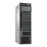
Juniper PTX5000 Hardware Manual (664 pages)
Packet Transport Router
Brand:
Juniper
| Category:
Network Router
| Size: 21.59 MB
Table of Contents
Table of Contents
3
About the Documentation
31
Documentation and Release Notes
31
Documentation Conventions
31
Supported Platforms
31
Table 1: Notice Icons
32
Table 2: Text and Syntax Conventions
32
About the Documentation
33
Documentation Feedback
33
Opening a Case with JTAC
34
Requesting Technical Support
34
Self-Help Online Tools and Resources
34
Chapter 1 System Overview and Architecture
37
Chapter 2 Chassis Components and Descriptions
37
Chapter 3 Cooling System Components and Descriptions
37
Chapter 4 Power System Components and Descriptions
37
Chapter 5 Host Subsystem Components and Description
37
Overview
37
System Overview and Architecture
39
PTX5000 Packet Transport Router Description
39
Figure 1: Front View of the PTX5000
40
Figure 2: Rear View of the PTX5000
41
PTX5000 Hardware Component Overview
41
System Overview and Architecture
41
Table 3: PTX5000 Hardware Components
42
PTX5000 Component Redundancy
44
PTX5000 System Architecture Description
45
PTX5000 Packet Transport Router Description
45
PTX5000 Hardware Component Overview
45
PTX5000 Packet Forwarding Engine Architecture
46
Chassis Components and Descriptions
47
PTX5000 Chassis Description
47
Figure
47
Rack
47
Figure 3: Front View of the PTX5000 Chassis
48
Figure 4: Rear View of the PTX5000 Chassis
49
Chassis Components and Descriptions
49
PTX5000 Midplane Description
50
Figure 5: ESD Points on the Packet Transport Router
50
PTX5000 Cable Management System
51
PTX5000 Craft Interface Description
52
Craft Interface Front Panel
52
Figure 6: Craft Interface
52
Craft Interface LCD
53
Figure 7: LCD in Idle Mode
53
Idle Mode
53
Alarm Mode
54
LCD Navigation Buttons
54
PTX5000 Craft Interface Leds
54
Figure 8: LCD in Alarm Mode
54
Craft Interface Alarm Leds
55
Figure 9: Craft Interface Leds
55
Craft Interface Host Subsystem Leds
56
Craft Interface SIB Leds
56
Table 4: Alarm Leds on the PTX5000 Craft Interface
56
Table 5: SIB Leds on the PTX5000 Craft Interface
56
Table 6: PTX5000 Host Subsystem Leds
56
CCG Leds
57
Fan Trays Leds
57
Table 7: PTX5000 CCG Leds
57
Table 8: Fan Tray Leds on the Craft Interface
57
Power Distribution Unit Leds
58
Power Supply Modules Leds
58
Table 10: PSM-LED Mapping
58
Table 11: Power Supply Module Leds on the Craft Interface
58
Table 9: Power Distribution Unit Leds
58
PTX5000 Centralized Clock Generator Description
59
CCG Components
59
CCG Function
59
CCG Slots
59
PTX5000 Centralized Clock Generator Leds
60
Figure 10: CCG
60
Table 12: CCG Leds
60
Table 13: CCG Port Leds
61
Cooling System Components and Descriptions
63
PTX5000 Cooling System Description
63
Fan Trays
63
Figure 11: Vertical Fan Tray
64
Air Filters
65
Airflow
65
Figure 12: FAN-PTX-H Horizontal Fan Tray
65
Figure 13: FAN3-PTX-H Horizontal Fan Tray
65
Figure 14: Airflow through the Chassis
65
Figure 15: Vertical Fan Tray Air Filter
66
Figure 16: Horizontal Fan Tray Air Filter
66
Figure 17: PSM Door Air Filter
67
Power Supply Cooling System
67
Power System Components and Descriptions
69
PTX5000 DC Power System Description
69
DC Pdus Supported on the PTX5000
69
PTX5000 DC Power Distribution Unit
69
PTX5000 Normal Capacity DC PDU
69
Table 14: DC Pdus Supported on the PTX5000
69
Figure 18: 60-A DC PDU
70
Figure 19: 60-A DC Input Terminals
71
Power System Components and Descriptions
71
Figure 20: 120-A DC PDU
72
Figure 21: High Capacity DC PDU
74
Figure 22: High Capacity DC Input Terminals
75
Figure 23: High Capacity DC Input Terminal Positions
75
Table 15: DC Psms Supported on the PTX5000
76
Figure 24: 60-A DC PSM and 120-A DC PSM
77
PTX5000 AC Power System Description
78
Figure 25: High Capacity DC PSM
78
AC Pdus Supported on the PTX5000
79
Normal Capacity Three-Phase Delta AC PDU Components
79
PTX5000 Normal Capacity Delta and Wye AC Pdus
79
Table 16: AC Pdus Supported on the PTX5000
79
Figure 26: Three-Phase Delta AC PDU
80
Figure 27: Three-Phase Delta AC Power Cord
81
Normal Capacity Three-Phase Wye AC PDU Components
81
Figure 28: Three-Phase Wye AC PDU
82
Figure 29: Three-Phase Wye AC Power Cord
83
PTX5000 High Capacity Delta and Wye AC PDU
83
High Capacity Delta AC PDU Components
84
Figure 30: High Capacity Delta AC PDU
85
Figure 31: AC Power Cord
86
High Capacity Wye AC PDU Components
86
Figure 32: High Capacity Wye AC PDU
87
Figure 33: AC Power Cord
88
PTX5000 High Capacity Single-Phase AC PDU
89
AC Psms Supported on the PTX5000
90
Figure 34: High Capacity Single-Phaseac PDU Components
90
High Capacity Single-Phase AC PDU Components
90
Figure 35: AC PSM
91
PTX5000 High Capacity AC PSM
91
PTX5000 Normal Capacity AC PSM
91
Table 17: AC Psms Supported on the PTX5000
91
Ptx5000 Power Distribution Unit Leds
92
60-A DC PDU Leds
92
Figure 36: High Capacity AC PSM
92
Figure 37: 60-A DC PDU
93
Table 18: 60-A DC PDU Leds
93
120-A DC PDU Leds
94
Figure 38: 120-A DC PDU Leds
94
Table 19: 120-A DC PDU Leds
94
Figure 39: High Capacity DC PDU Leds
95
High Capacity DC PDU Leds
95
Table 20: High Capacity DC PDU Leds
95
Figure 40: Three-Phase Delta AC PDU Leds
96
Three-Phase Delta AC PDU Leds
96
Table 21: Three-Phase Delta AC PDU Leds
97
Three-Phase Wye AC PDU Leds
97
Figure 41: Three-Phase Wye AC PDU Leds
98
High Capacity Delta AC PDU Leds
99
Table 22: Three-Phase Wye AC PDU Leds
99
Figure 42: High Capacity Delta AC PDU Leds
100
High Capacity Wye AC PDU
100
Table 23: High Capacity Delta AC PDU Leds
100
Figure 43: High Capacity Wye AC PDU Leds
101
Table 24: High Capacity Wye AC PDU Leds
101
PTX5000 Power Supply Module Leds
102
AC Power Supply Module Leds
102
Figure 44: AC PSM Leds
103
Table 25: AC Power Supply Module Leds
103
60-A and 120-A DC Power Supply Module Leds
104
High Capacity AC Power Supply Module Leds
104
Table 26: High Capacity AC Power Supply Module Leds
104
Figure 45: DC PSM Leds
105
High Capacity DC Power Supply Module Leds
105
Table 27: DC Power Supply Module Leds
105
Figure 46: High Capacity DC PSM Leds
106
Table 28: High Capacity DC Power Supply Module Leds
106
Understanding Normal-Capacity Power System Power Zones
107
Normal-Capacity Power Zones and PSM Fault Tolerance
107
PSM Slots
107
Table 29: Components Powered by each Zone
107
Table 30: Power Zone 0 Fault Tolerance
108
Table 31: Power Zone 1 Fault Tolerance
108
Table 32: Power Zone 2 Fault Tolerance
109
Host Subsystem Components and Description
111
PTX5000 Host Subsystem Description
111
PTX5000 Routing Engine Description
112
Routing Engine Functions
112
Routing Engine Slots
112
Figure 47: RE-DUO-C2600 Routing Engine
113
Host Subsystem Components and Description
113
RE-DUO-C2600-16G Routing Engine Components
113
Figure 48: RE-PTX-X8-64G Routing Engine Components
114
RE-PTX-X8-64G Routing Engine Components
114
Routing Engine Boot Sequence
115
Figure 49: RE-DUO-C2600-16G Routing Engine Leds
116
PTX5000 Routing Engine Leds
116
Routing Engine Leds (RE-DUO-C2600-16G)
116
Table 33: Routing Engine Leds
116
Figure 50: RE-PTX-X8-64G Routing Engine Leds
117
Routing Engine Leds (RE-PTX-X8-64G)
117
PTX3000 Routing Engines
118
PTX5000 Routing Engines
118
Routing Engines Supported on PTX Series Routers
118
Table 34: PTX3000 Routing Engines
118
Table 35: PTX5000 Routing Engines
118
PTX Series Routing Engine Specifications
119
PTX5000 Control Board Description
119
Table 36: PTX Series Routing Engine Specifications
119
Control Board CB-PTX Components
120
Control Board Function
120
Control Board Slots
120
Figure 51: Control Board
121
Control Board CB2-PTX Components
122
Figure 52: Control Board (CB2-PTX)
122
PTX5000 Control Board Leds
123
Figure 53: Control Board CB-PTX Leds
124
Table 37: Control Board CB-PTX Leds
124
Table 38: Control Board CB-PTX Port Leds
124
Figure 54: Control Board CB2-PTX Leds
125
Table 39: Control Board CB2-PTX Leds
125
Table 40: Control Board CB2-PTX Port Leds
126
Chapter 6 Switch Fabric Components and Descriptions
127
PTX5000 Switch Interface Board Description
127
SIB Components
127
SIB Function
127
SIB Slots
127
Sibs Supported on the PTX5000
127
PTX5000 Switch Interface Board Leds
128
Figure 55: SIB-I-PTX5008 SIB
128
Figure 56: SIB2-I-PTX5K SIB
128
Figure 57: SIB3-I-PTX5K SIB
128
Figure 58: SIB Leds
128
Switch Fabric Components and Descriptions
129
Table 41: SIB Leds
129
Interface Module Components and Descriptions
131
Chapter 7 Interface Module Components and Descriptions
131
PTX5000 FPC Description
131
FPC Function
131
FPC Slots
131
Table 42: Fpcs Supported on the PTX5000
131
Figure 59: Identifying the Fpcs
132
FPC Components
132
FPC Terminology
132
Identifying the Fpcs
132
Fpcs Supported on the PTX5000
133
Figure 60: FPC Edges
133
PTX5000 FPC Leds
134
Table 43: PTX5000 FPC Leds
134
PTX5000 FPC Description
134
PTX5000 PIC Description
135
Pics Supported on the PTX5000
135
PTX5000 PIC Components
135
PTX5000 PIC Function
135
PTX5000 PIC Slots
135
Pics Supported on the PTX Series
136
Figure 61: PIC Faceplate
136
Table 44: Pics Supported on the PTX Series
137
PTX Series PIC/FPC Compatibility
138
PTX3000 PIC/FPC Compatibility
138
Table 45: PTX3000 PIC/FPC Compatibility
139
PTX5000 PIC/FPC Compatibility
140
Table 46: PTX5000 PIC/FPC Compatibility
140
Switch Fabric Components and Descriptions
37
Interface Module Components and Descriptions
37
Chapter 8 Planning and Preparing the Site
143
AC Power Specifications and Requirements
143
DC Power Specifications and Requirements
143
Site Planning, Preparation, and Specifications
143
Planning and Preparing the Site
145
Overview of Preparing the Site for the PTX5000 Packet Transport Router
145
Specifications
145
Planning and Preparing the Site
147
PTX5000 Packet Transport Router Environmental Specifications
147
Table 47: PTX5000 Environmental Specifications
147
General Site Guidelines
148
PTX5000 Chassis Grounding Cable and Lug Specifications
148
Figure 62: 0-AWG Grounding Cable Lug
149
Figure 63: 4-AWG Grounding Cable Lug
149
Specifications
149
Table 48: Grounding Cable Specifications
149
Table 49: PTX5000 AC PDU Electrical and External Circuit Breaker
150
Table 50: PTX5000 DC PDU Electrical and External Circuit Breaker
150
Figure 64: Chassis Dimensions and Clearance Requirements
151
PTX5000 Clearance Requirements for Airflow and Hardware Maintenance
151
PTX5000 Physical Specifications
152
Table 51: Physical Specifications
152
Site Electrical Wiring Guidelines
154
Table 52: Site Electrical Wiring Guidelines
154
Rack Requirements for the PTX5000 Packet Transport Router
155
Rack Size and Strength
155
Connection to Building Structure
157
Figure 65: Typical Open-Frame Rack
157
Spacing of Mounting Bracket and Flange Holes
157
Chapter 9 Calculating System Power Requirements
159
Calculating PTX5000 Power Consumption
159
Power Requirements for PTX5000 Components
159
Calculating System Power Requirements
159
Table 53: Power Requirements for PTX5000 Components
160
Calculating Power Consumption for Your Configuration
161
Calculating System Power Requirements
161
Calculating System Thermal Output
162
Chapter 10 AC Power Specifications and Requirements
165
PTX5000 AC Power System Specifications
165
Table 54: AC Power System Electrical Specifications
165
PTX5000 Three-Phase Delta AC Power Distribution Unit Specifications
166
PTX5000 Three-Phase Wye AC Power Distribution Unit Specifications
166
Table 55: Three-Phase Delta AC PDU Electrical Specifications
166
Table 56: Three-Phase Wye AC PDU Electrical Specifications
166
PTX5000 High Capacity Delta AC Power Distribution Unit Specifications
167
PTX5000 High Capacity Wye AC Power Distribution Unit Specifications
167
AC Power Specifications and Requirements
167
Table 57: High Capacity Delta AC PDU Electrical Specifications
167
Table 58: High Capacity Wye AC PDU Electrical Specifications
167
PTX5000 AC Power Cord Specifications
168
PTX5000 High Capacity Single-Phase AC Power Distribution Unit Specifications
168
Table 59: High Capacity Single-Phase AC PDU Electrical Specifications
168
Table 60: AC Power Cord Specifications for the Three-Phase AC Power
169
Figure 66: Three-Phase Delta AC Power Cord
170
Figure 67: Three-Phase Wye AC Power Cord
170
Figure 68: Three-Phase Delta 60-A Plug Type (North America)
171
Figure 69: Three-Phase Delta 100-A Plug Type (North America)
171
Figure 70: Three-Phase Delta 150-A Plug Type (North America)
171
Figure 71: Three-Phase Wye 32-A Plug Type (Europe)
172
Figure 72: Three-Phase Wye 63-A Plug Type (Europe)
172
Table 61: AC Power Cord Specifications for the High Capacity Single-Phase AC
172
Figure 73: Single-Phase 30-A Plug Type
173
Cords
173
Figure 74: Single-Phase 20-A Plug Type
174
Chapter 11 DC Power Specifications and Requirements
175
PTX5000 DC Power System Electrical Specifications
175
Table 62: Power System Electrical Specifications
175
Table 63: High Capacity Power System Electrical Specifications
175
PTX5000 DC Power Distribution Unit Specifications
176
Table 64: 60-A DC PDU Electrical Specifications
176
Table 65: 120-A PDU Electrical Specifications
176
Table 66: High Capacity PDU Electrical Specifications
176
PTX5000 DC Power Cable and Lugs Specifications
177
DC Power Cables
177
DC Power Specifications and Requirements
177
Table 67: Power Cable Specifications
177
DC Power Lugs
178
Table 68: DC Power Cable Specifications
178
Figure 75: 0-AWG DC Power Cable Lug
179
Figure 76: 4-AWG DC Power Cable Lug
179
PTX5000 DC Power Distribution
179
Figure 77: Typical DC Source Cabling to the Packet Transport Router
180
Chapter 12 Network Cable and Transceiver Planning
181
Understanding Fiber-Optic Cable Signal Loss, Attenuation, and Dispersion
181
Attenuation and Dispersion in Fiber-Optic Cable
181
Signal Loss in Multimode and Single-Mode Fiber-Optic Cable
181
Calculating Power Budget and Power Margin for Fiber-Optic Cables
182
Calculating Power Budget for Fiber-Optic Cable
182
Calculating Power Margin for Fiber-Optic Cable
183
Network Cable and Transceiver Planning
183
Table 69: Estimated Values for Factors Causing Link Loss
183
Chapter 13 Alarm and Management Cable Specifications and Pinouts
185
PTX5000 Alarm Relay Contact Wire Specifications
185
PTX5000 Management Interface Cable Specifications
185
Table 70: Cable Specifications for Routing Engine Management
185
RJ-45 Connector Pinouts for the PTX5000 Auxiliary and Console Ports
186
Port
186
Table 71: RJ-45 Connector Pinouts for the PTX5000 Auxiliary and Console
186
Alarm and Management Cable Specifications and Pinouts
187
Table 72: RJ-45 Connector Pinouts
187
Initial Installation and Configuration
189
Connecting the Router to External Devices
189
Connecting the Router to Ground
189
Installing the Front Door on the Router
189
Installing the Mounting Hardware
189
Installing the Router into a Rack
189
Unpacking the Router
189
Installation Overview
191
Overview of Installing the PTX5000 Packet Transport Router
191
Chapter 14 Installation Overview
191
PTX5000 Installation Safety Guidelines
192
Chassis Lifting Guidelines
193
General Installation Safety Guidelines
193
Chapter 15 Unpacking the Router
195
Overview of Unpacking the PTX5000 Packet Transport Router
195
Tools and Parts Required to Unpack the PTX5000 Packet Transport Router
195
Unpacking the PTX5000 Packet Transport Router
196
Figure 78: Contents of the Shipping Crate
197
Verifying the PTX5000 Packet Transport Router Parts Received
198
Table 73: Packet Transport Router Parts List
198
Table 74: Accessory Box Parts List
199
Chapter 16 Installing the Mounting Hardware
201
Installing the PTX5000 Mounting Hardware for a Four-Post Rack or Cabinet
201
Installing Cage Nuts, if Needed
201
Table 75: Mounting Hole Locations for Installing the Four-Post Mounting Shelf and Rear Support Bracket
201
Four-Post Rack
202
Table 76: Mounting Hole Locations for Installing a PTX5000 in a Four-Post
202
Installing the Four-Post Mounting Shelf and Rear Support Bracket
203
Figure 79: Installing the Mounting Hardware for a Four-Post Rack
204
Removing the Center-Mounting Brackets
204
Installing the PTX5000 Mounting Hardware for an Open-Frame Rack
205
Figure 80: Removing the Center-Mounting Bracket
205
Installing Cage Nuts, if Needed
205
Table 77: Mounting Hole Locations for Installing a PTX5000 Open-Frame Rack
206
Table 78: Mounting Hole Locations for Installing a Chassis in an Open-Frame
206
Installing the Open-Frame Rack Mounting Shelf
207
Figure 81: Installing the Mounting Hardware for an Open-Frame Rack
208
Chapter 17 Installing the Router into a Rack
209
Overview of Installing a PTX5000 Packet Transport Router Using a Mechanical
209
Lift
209
Tools Required to Install the PTX5000 Packet Transport Router Using a
210
Mechanical Lift
210
Installing the PTX5000 by Using a Mechanical Lift
210
Figure 82: Loading the PTX5000 Onto the Lift
212
Figure 83: Installing the PTX5000 in an Open-Frame Rack
213
Figure 84: Installing the PTX5000 in a Four-Post Rack
214
Chapter 18 Installing the Front Door on the Router
215
Rack
215
Installing the Front Door on a PTX5000 Packet Transport Router in an Open-Frame Rack
217
Figure 85: Installing the Front Door on a PTX5000 Packet Transport Router in
217
Figure 86: Installing Brackets on the Front-Mounting Flanges
219
Figure 87: Installing the Front Door on a PTX5000 Router in an Open-Frame
220
Chapter 19 Connecting the Router to Ground
221
Tools and Parts Required to Ground the PTX5000 Packet Transport Router
221
Connecting the PTX5000 Grounding Cable
221
Figure 88: Connecting the Grounding Cable
222
Advertisement
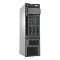
Juniper PTX5000 Hardware Manual (721 pages)
Packet Transport Router
Brand:
Juniper
| Category:
Network Router
| Size: 8.74 MB
Table of Contents
Table of Contents
3
About this Guide
18
Overview
19
Ptx5000 System Overview/Ptx5000 Description
20
Benefits of the PTX5000 Router
20
PTX5000 Description
20
PTX5000 System Overview
20
System Overview
21
PTX5000 Packet Forwarding Engine Architecture
24
PTX5000 System Architecture Description
24
PTX5000 Hardware Component Overview
25
PTX5000 Component Redundancy
29
PTX5000 Field-Replaceable Units
30
In this Section
31
PTX5000 Chassis
31
PTX5000 Chassis Description
32
PTX5000 Cable Management System
36
PTX5000 Midplane Description
36
PTX5000 Craft Interface Description
37
Ptx5000 Craft Interface Leds
41
Craft Interface Alarm Leds
42
Craft Interface SIB Leds
42
Craft Interface Host Subsystem Leds
43
CCG Leds
44
Fan Trays Leds
44
Power Distribution Unit Leds
45
Power Supply Modules Leds
45
PTX5000 Centralized Clock Generator Description
47
PTX5000 Centralized Clock Generator Leds
48
PTX5000 Cooling System
50
PTX5000 AC Power System
56
PTX5000 AC Power System Description
57
PTX5000 AC Power Distribution Unit Leds
76
PTX5000 AC Power Supply Module Leds
88
PTX5000 AC Power System Specifications
91
PTX5000 Three-Phase Delta AC Power Distribution Unit Specifications
92
PTX5000 Three-Phase Wye AC Power Distribution Unit Specifications
92
PTX5000 High Capacity Delta AC Power Distribution Unit Specifications
93
PTX5000 High Capacity Single-Phase AC Power Distribution Unit Specifications
94
PTX5000 High Capacity Wye AC Power Distribution Unit Specifications
94
PTX5000 AC Power Cord Specifications
95
PTX5000 DC Power System
104
PTX5000 DC Power System Description
104
PTX5000 DC Power Distribution Unit Leds
117
PTX5000 DC Power Supply Module Leds
123
PTX5000 DC Power System Electrical Specifications
127
PTX5000 DC Power Distribution Unit Specifications
128
PTX5000 DC Power Cable and Lugs Specifications
129
PTX5000 DC Power Distribution
132
PTX5000 Host Subsystem
134
PTX5000 Host Subsystem Description
134
Routing Engine Slots
135
PTX5000 Routing Engine Description
135
Routing Engine Functions
135
RE-DUO-C2600-16G Routing Engine Components
136
RE-PTX-X8-64G Routing Engine Components
138
RE-PTX-X8-128G Routing Engine Components
139
Routing Engine Boot Sequence
140
PTX5000 Routing Engine Leds
141
Routing Engines Supported on PTX Series Routers
144
PTX5000 Control Board Description
149
PTX5000 Control Board Leds
153
PTX5000 Switch Interface Boards
157
PTX5000 Switch Interface Board Description
158
PTX5000 Switch Interface Board Leds
160
PTX5000 FPC Description
161
PTX5000 Interface Modules
161
Fpcs Supported on the PTX5000
165
PTX5000 FPC Leds
166
PTX5000 PIC Description
166
Pics Supported on the PTX Series
168
PTX Series PIC/FPC Compatibility
171
Site Planning, Preparation, and Specifications
177
Overview of Preparing the Site for the PTX5000
178
PTX5000 Environmental Specifications
180
PTX5000 Site Guidelines and Requirements
180
General Site Guidelines
181
PTX5000 Chassis Grounding Cable and Lug Specifications
182
PTX5000 AC and DC PDU Electrical and External Circuit Breaker Specifications
184
PTX5000 Clearance Requirements for Airflow and Hardware Maintenance
186
PTX5000 Physical Specifications
187
Site Electrical Wiring Guidelines
191
Rack Requirements for the PTX5000
192
Calculating PTX5000 Power Consumption
195
PTX5000 Power Planning
195
Power Requirements for PTX5000 Components
196
Calculating Power Consumption for Your Configuration
198
Calculating System Thermal Output
200
Understanding Normal-Capacity Power System Power Zones
200
Determining Transceiver Support and Specifications
205
Network Cable and Transceiver Planning
205
Fiber-Optic Cable Signal Loss, Attenuation, and Dispersion
206
Calculating Power Budget and Power Margin for Fiber-Optic Cables
208
How to Calculate Power Budget for Fiber-Optic Cables
208
How to Calculate Power Margin for Fiber-Optic Cables
208
PTX5000 Alarm and Management Cable Specifications and Pinouts
210
PTX5000 Alarm Relay Contact Wire Specifications
210
PTX5000 Management Interface Cable Specifications
211
RJ-45 Connector Pinouts for the PTX5000 Auxiliary and Console Ports
212
Connector Pinouts for the PTX5000 Management HOST/ETHERNET Port
213
Initial Installation and Configuration
214
Overview of Installing the PTX5000
215
PTX5000 Installation Overview
215
PTX5000 Installation Safety Guidelines
216
Overview of Unpacking the PTX5000
218
Tools and Parts Required to Unpack the PTX5000
218
Unpacking the PTX5000
218
Unpacking the PTX5000
219
Verifying the PTX5000 Parts Received
221
Installing Cage Nuts, if Needed
224
Installing the PTX5000 in a Rack
224
Installing the PTX5000 Mounting Hardware for a Four-Post Rack or Cabinet
224
Installing the Four-Post Mounting Shelf and Rear Support Bracket
226
Removing the Center-Mounting Brackets
227
Installing Cage Nuts, if Needed
229
Installing the PTX5000 Mounting Hardware for an Open-Frame Rack
229
Installing the Open-Frame Rack Mounting Shelf
230
Overview of Installing a PTX5000 Using a Mechanical Lift
231
Installing the PTX5000 by Using a Mechanical Lift
232
Tools Required to Install the PTX5000 Using a Mechanical Lift
232
Connecting the PTX5000 Grounding Cable
238
Connecting the PTX5000 to Earth Ground
238
Tools and Parts Required to Ground the PTX5000
238
Juniper PTX5000 Hardware Manual (320 pages)
Packet Transport Switch
Brand:
Juniper
| Category:
Switch
| Size: 9.51 MB
Table of Contents
Table of Contents
3
About the Documentation
21
Junos os Documentation and Release Notes
21
Objectives
21
Audience
22
Documentation Conventions
22
Table 1: Notice Icons
22
Table 2: Text and Syntax Conventions
22
Documentation Feedback
23
About the Documentation
23
Requesting Technical Support
24
Self-Help Online Tools and Resources
24
Opening a Case with JTAC
25
Chapter 1 PTX5000 Packet Transport Switch Overview
27
PTX5000 Packet Transport Switch Overview
29
PTX5000 Packet Transport Switch Description
29
Figure 1: Front View of the PTX5000 Packet Transport Switch
30
Figure 2: Rear View of the PTX5000 Packet Transport Switch
31
Chapter 3 PTX5000 Hardware Components Overview
27
Chapter 2 PTX5000 Packet Transport Switch System Architecture Overview
33
PTX5000 System Architecture Description
33
PTX5000 Packet Forwarding Engine Architecture
33
PTX5000 Hardware Components Overview
35
PTX5000 Hardware Component Overview
35
Table 3: PTX5000 Hardware Components
35
PTX5000 Component Redundancy
37
PTX5000 Chassis Description
38
Figure 3: Front View of PTX5000 Chassis
39
PTX5000 Midplane Description
40
Figure 4: Rear View of PTX5000 Chassis
40
PTX5000 Cable Management System
41
PTX5000 Centralized Clock Generator Overview
41
PTX5000 Centralized Clock Generator Description
42
CCG Slots
42
CCG Function
42
CCG Components
42
Figure 5: CCG
42
PTX5000 Centralized Clock Generator Leds
43
PTX5000 Cooling System Overview
43
Table 4: CCG Leds
43
Table 5: CCG Port Leds
43
PTX5000 Cooling System Description
44
Fan Trays
44
Figure 6: Vertical Fan Tray
44
Airflow
45
Figure 7: Horizontal Fan Tray
45
Air Filters
46
Figure 8: Airflow through the Chassis
46
Figure 9: Vertical Fan Tray Air Filter
46
Power Supply Cooling System
47
Figure 10: Horizontal Fan Tray Air Filter
47
Figure 11: PSM Door Air Filter
47
PTX5000 Control Board Overview
48
PTX5000 Control Board Description
48
Control Board Slots
48
Control Board Function
48
Control Board Components
48
Figure 12: Control Board
49
PTX5000 Control Board Leds
50
Figure 13: Control Board Leds
50
Table 6: Control Board Leds
50
PTX5000 Craft Interface Overview
51
Table 7: Control Board Port Leds
51
PTX5000 Craft Interface Description
52
Craft Interface Front Panel
52
Figure 14: Craft Interface
52
Craft Interface LCD
53
Figure 15: LCD in Idle Mode
53
LCD Navigation Buttons
54
PTX5000 Craft Interface Leds
54
Figure 16: LCD in Alarm Mode
54
Craft Interface Alarm Leds
55
Figure 17: Craft Interface Leds
55
Table 8: Alarm Leds on the PTX5000 Craft Interface
55
CCG Leds
56
Craft Interface Host Subsystem Leds
56
Craft Interface SIB Leds
56
Table 10: PTX5000 Host Subsystem Leds
56
Table 9: SIB Leds on the PTX5000 Craft Interface
56
Fan Trays Leds
57
Table 11: PTX5000 CCG Leds
57
Table 12: Power Supply Module Leds on the Craft Interface
57
Table 13: Fan Tray Leds on the Craft Interface
57
PTX5000 FPC Overview
58
PTX5000 FPC Description
58
FPC Slots
58
FPC Function
58
FPC Components
58
FPC Terminology
59
Identifying the Fpcs
59
Figure 18: FPC Edges
59
PTX5000 FPC Leds
60
Figure 19: FPC Supported by the Packet Transport Switch
60
Table 14: PTX5000 FPC Leds
60
PTX5000 Fpcs Supported
61
PTX5000 Host Subsystem Description
61
Table 15: Fpcs Supported by the PTX5000 Packet Transport Switch
61
PTX5000 PIC Overview
62
PTX Series PIC Description
62
PTX5000 Power System Overview
63
PTX5000 Power System Description
63
PTX5000 DC Power Distribution Unit
63
Figure 20: PIC
63
Figure 21: PDU
64
Table 16: Supported Power Distribution Units
64
PTX5000 DC Power Supply Module
65
Table 17: Supported Power Distribution Units
65
Figure 22: PSM
66
Table 18: Components Powered by each Zone
66
Table 19: Power Zone Fault Tolerance
67
PTX5000 Power Distribution Unit Leds
68
Figure 23: PDU
68
Table 20: Power Distribution Unit Leds
68
PTX5000 Power Supply Module Leds
69
Figure 24: PSM Leds
69
Table 21: Power Supply Module Leds
69
PTX5000 Routing Engine Overview
70
PTX5000 Routing Engine Description
70
Routing Engine Slots
70
Routing Engine Functions
70
Routing Engine Components
71
Routing Engine Boot Sequence
72
Figure 25: C2600 Routing Engine
72
PTX5000 Routing Engine Leds
73
Figure 26: Routing Engine Leds
73
Table 22: Routing Engine Leds
73
PTX5000 Switch Interface Board Overview
74
PTX5000 Switch Interface Board Description
74
SIB Slots
74
SIB Function
74
Supported Sibs
74
SIB Components
74
Figure 27: SIB
74
PTX5000 Switch Interface Board Leds
75
Figure 28: SIB
75
Table 23: SIB Leds
75
PTX5000 Packet Transport Switch Initial Installation
77
Chapter 5 Preparing for PTX5000 Packet Transport Switch Installation
77
Grounding the PTX5000 Packet Transport Switch
77
Installing the PTX5000 Packet Transport Switch Mounting Hardware
77
Chapter 4 PTX5000 Packet Transport Switch Installation Summary
79
Overview of Installing the PTX5000 Packet Transport Switch
79
Preparing for PTX5000 Packet Transport Switch Installation
81
Overview of Preparing the Site for the PTX5000 Packet Transport Switch
81
Rack Requirements for the PTX5000 Packet Transport Switch
82
Rack Size and Strength
82
Spacing of Mounting Bracket and Flange Holes
84
Connection to Building Structure
84
Figure 29: Typical Open-Frame Rack
84
PTX5000 Clearance Requirements for Airflow and Hardware Maintenance
85
Figure 30: Chassis Dimensions and Clearance Requirements
85
Unpacking the PTX5000 Packet Transport Switch
87
Chapter 6 Unpacking the PTX5000 Packet Transport Switch
87
Overview of Unpacking the PTX5000 Packet Transport Switch
87
Tools and Parts Required to Unpack the PTX5000 Packet Transport Switch
87
Unpacking the PTX5000 Packet Transport Switch
88
Figure 31: Contents of the Shipping Crate
89
Verifying the PTX5000 Packet Transport Switch Parts Received
89
Table 24: Packet Transport Switch Parts List
90
Table 25: Accessory Box Parts List
90
Chapter 7 Installing the PTX5000 Packet Transport Switch Mounting Hardware
93
Installing the PTX5000 Mounting Hardware for a Four-Post Rack or Cabinet
93
Installing Cage Nuts, if Needed
93
Table 26: Mounting Hole Locations for Installing the Four-Post Mounting Shelf and Rear-Support Bracket
93
Table 27: Mounting Hole Locations for Installing a PTX5000 Packet Transport Switch Chassis in a Four-Post Rack
94
Installing the Four-Post Mounting Shelf and Rear Support Bracket
95
Installing the PTX5000 Packet Transport Switch Mounting Hardware
95
Removing the Center-Mounting Brackets
96
Figure 32: Installing the Mounting Hardware for a Four-Post Rack
96
Installing the PTX5000 Mounting Hardware for an Open-Frame Rack
97
Installing Cage Nuts, if Needed
97
Figure 33: Center-Mounting Bracket Removal
97
Installing the Open-Frame Rack Mounting Shelf
99
Figure 34: Installing the Mounting Hardware for an Open-Frame Rack
99
Chapter 8 Installingtheptx5000Packettransportswitchusingamechanical
101
Lift
101
Overview of Installing a PTX5000 Packet Transport Switch Using a Mechanical
101
Installing the PTX5000 Packet Transport Switch Using a Mechanical
101
Mechanical Lift
102
Installing the PTX5000 Packet Transport Switch Using a Mechanical Lift
102
Figure 35: Loading the PTX5000 Onto the Lift
104
Figure 36: Installing the PTX5000 Packet Transport Switch in an Open-Frame
105
Figure 37: Installing the PTX5000 Packet Transport Switch in a Four-Post
106
Table 30: Mounting Hole Locations for Installing a Chassis in an Open-Frame
106
Table 31: Mounting Hole Locations for Installing a PTX5000 Packet Transport
107
Chapter 9 Grounding the PTX5000 Packet Transport Switch
109
Tools and Parts Required to Ground the PTX5000 Packet Transport Switch
109
Connecting the PTX5000 Grounding Cable
109
Figure 38: Connecting the Grounding Cable
110
Chapter 10 Connectingtheptx5000Packettransportswitchtoexternal
111
Devices
111
Tools and Parts Required to Connect the PTX5000 Packet Transport Switch to External Devices
111
Connecting the PTX5000 Packet Transport Switch to External
111
Connecting the PTX5000 Packet Transport Switch to a Management Console or Auxiliary Device
112
Figure 39: Connecting to the Console or Auxiliary Port on the Control Board
112
Connecting the PTX5000 Packet Transport Switch to a Management Console or
112
Auxiliary Device
112
Connecting the PTX5000 Packet Transport Switch to an External Alarm-Reporting Device
113
Connecting PIC Cables to the PTX5000 Packet Transport Switch
113
Device
113
Figure 40: Connecting PIC Cables
115
Device
116
Figure 41: Routing Engine Ethernet Cable Connector
116
Connecting the PTX5000 Packet Transport Switch to an External Clocking Device
117
Figure 42: Connecting to the Host/Ethernet Port on the Control Board
117
Chapter 11 Providing Power to the PTX5000 Packet Transport Switch
119
Switch
119
Connecting DC Power to the PTX5000 Packet Transport Switch
120
Figure 43: Removing the Input Power Tray
120
Figure 44: Connecting the DC Source Power Cable Lugs to an Input Power
121
Powering on the DC Powered PTX5000 Packet Transport Switch
122
Figure 45: Installing an Input Power Tray
122
Powering off the PTX5000 Packet Transport Switch
124
Chapter 12 Configuring the Junos os
127
Advertisement
Juniper PTX5000 Quick Start Manual (82 pages)
Packet Transport Router
Brand:
Juniper
| Category:
Network Router
| Size: 4.55 MB
Table of Contents
Table of Contents
1
Quick Start Description
3
Step 1: Prepare the Site for the PTX5000
4
Rack-Mounting Requirements
4
Tools Required to Unpack and Install the PTX5000
5
Step 2: Unpack the PTX5000
6
Step 3: Install the PTX5000 Mounting Hardware
7
Install the PTX5000 Mounting Hardware for a Four-Post Rack or Cabinet
7
Install Cage Nuts, if Needed
7
Install the Four-Post Mounting Shelf and Rear Support Bracket
9
Remove the Center-Mounting Brackets
10
Install the PTX5000 Mounting Hardware for an Open-Frame Rack
11
Install Cage Nuts, if Needed
11
Install the Open-Frame Rack Mounting Shelf
13
Step 4: Install the PTX5000
14
Step 5: Connect the PTX5000 Grounding Cable
18
Step 6: Install the Front Door on a PTX5000
19
Step 7: Connect External Devices and PIC Cables to the PTX5000
19
Connect to a Console or Auxiliary Device
19
Connect to a Network for Out-Of-Band Management
21
Connect the PIC Cables
22
Step 8: Connect Power to the PTX5000 Router
24
Connect Power to the PTX5000 60-A DC Input Power Trays
24
Connect Power to the PTX5000 120-A DC Input Power Trays
29
Connect Power to the PTX5000 Three-Phase Delta AC Pdus
32
Connect Power to the PTX5000 Three-Phase Wye AC Pdus
36
Connect Power to the PTX5000 High Capacity DC Pdus
42
Connect Power to the PTX5000 High Capacity Delta AC Pdus
45
Connect Power to the PTX5000 High Capacity Wye AC Pdus
52
Connect Power to the PTX5000 High Capacity Single-Phase AC Pdus
57
Step 9: Power on the PTX5000
62
Power on a PTX5000 with 60-A DC Pdus
62
Power on a PTX5000 with 120-A DC Pdus
64
Power on a PTX5000 with High Capacity DC Pdus
66
Power on a PTX5000 with Three-Phase AC Pdus
68
Power on a PTX5000 with High Capacity Single-Phase AC Pdus
69
Step 10: Perform the PTX5000 Initial Software Configuration
71
Enter Configuration Mode
72
Configure User Accounts and Passwords
72
Configure System Attributes
73
Commit the Configuration
75
Safety Warnings
76
PTX5000 Compliance Statements for NEBS
78
Compliance Statements for EMC Requirements
78
Canada
79
European Community
79
Israel
79
Japan
79
United States
80
Junos os Documentation and Release Notes
80
Requesting Technical Support
80
Self-Help Online Tools and Resources
81
Creating a Service Request with JTAC
81
Revision History
81
Advertisement
Related Products
Juniper PTX10002-60C
Juniper PTX10003-160C
Juniper PTX10003-80C
Juniper PTX3000
Juniper PTX1000
Juniper PTX10001-36MR
Juniper PTX10004
Juniper PTX10016
Juniper PTX10008
Juniper PTX10004-BASE3
Juniper Categories
Network Router
Switch
Gateway
Software
Network Hardware
More Juniper Manuals
Login
Sign In
OR
Sign in with Facebook
Sign in with Google
Upload manual
Upload from disk
Upload from URL