Xerox Phaser 6180MFP Service Manual
Multifunction printer
Hide thumbs
Also See for Phaser 6180MFP:
- User manual (248 pages) ,
- Features setup manual (103 pages) ,
- Quick use manual (17 pages)
Table of Contents
Advertisement
Quick Links
Advertisement
Table of Contents
Troubleshooting

Related Manuals for Xerox Phaser 6180MFP


Summary of Contents for Xerox Phaser 6180MFP
- Page 1 Service Manual 701P47020 Phaser 6180MFP ® Multifunction Printer...
-
Page 3: Service Manual
Service Manual 701P47020 ® Phaser 6180MFP Warning The following servicing instructions are for use by qualified service personnel only. To avoid personal injury, do not perform any servicing other than that contained in the operating instructions, unless you are qualified to do so. First Printing: September 2007... - Page 4 Xerox technical training materials and service manuals are intended for use by authorized Xerox service technicians and service partners only and are not for resale. These materials may not be distributed, copied, or otherwise reproduced without prior written consent from Xerox Corporation.
-
Page 5: Service Terms
Caution: A personal injury hazard exists that may not be apparent. For example, a panel may cover the hazardous area. Danger: A personal injury hazard exists in the area where you see the sign. Phaser 6180MFP Multifunction Printer Service Manual... -
Page 6: Symbols Marked On The Product
Do not touch the item. Do not expose the item to sunlight. Do not expose the item to light. Do not burn the Print Cartridge. Do not expose the Print Cartridge to sunlight. Recycle the item. Phaser 6180MFP Multifunction Printer Service Manual... -
Page 7: Power Safety Precautions
Phaser 6180MFP Multifunction Printer Service Manual... -
Page 8: Electrostatic Discharge Precautions
Handle IC’s and Erasable Programmable Read-Only Memories (EPROM’s) carefully to avoid bending pins. Pay attention to the direction of parts when mounting or inserting them on Printed Circuit Boards (PCB’s). Phaser 6180MFP Multifunction Printer Service Manual... -
Page 9: Service Safety Summary
Class 1 Laser Product The Phaser 6180MFP is certified to comply with Laser Product Performance Standards set by the U.S. Department of Health and Human Services as a Class 1 Laser Product. This means that this product does not emit hazardous laser radiation;... -
Page 10: Servicing Electrical Components
This printer uses heat to fuse the toner image to paper. The Fuser is VERY HOT. Turn the printer power Off and wait at least 5 minutes for the Fuser to cool before attempting to service the Fuser or adjacent components. viii Phaser 6180MFP Multifunction Printer Service Manual... -
Page 11: Regulatory Information
Consult the dealer or an experienced radio/television technician for help. Any changes or modifications not expressly approved by Xerox could void the user's authority to operate the equipment. To ensure compliance with Part 15 of the FCC rules, use shielded interface cables. - Page 12 European Union The CE mark applied to this product symbolizes Xerox’s declaration of conformity with the following applicable Directives of the European Union as of the dates indicated: January 1, 1995: Low Voltage Directive 73/23/EEC as amended by 93/68/EEC January 1, 1996: Electromagnetic Compatibility Directive 89/336/EEC March 9, 1999: Radio &...
-
Page 13: Copy Regulations
Certificates may be photographed. Passports. Foreign Passports may be photographed. Immigration papers. Draft Registration Cards. Selective Service Induction papers that bear any of the following Registrant’s information: Earnings or Income Court Record Physical or mental condition Phaser 6180MFP Multifunction Printer Service Manual... - Page 14 The above list is provided for your convenience and assistance, but it is not all-inclusive, and no liability is assumed for its completeness or accuracy. In case of doubt, consult your solicitor. Phaser 6180MFP Multifunction Printer Service Manual...
- Page 15 Copyright material or trademarks without the consent of the owner Postage stamps and other negotiable instruments This list is not inclusive and no liability is assumed for either its completeness or accuracy. In case doubts, contact your legal counsel. Phaser 6180MFP Multifunction Printer Service Manual xiii...
-
Page 16: Fax Regulations
0.3). For earlier products, the REN is separately shown on the label. To order the correct service from the local telephone company, please provide the Facility Interface Code (FIC) and Service Order Code (SOC) listed below: FIC: 02LS2 SOC: 9.0F Phaser 6180MFP Multifunction Printer Service Manual... - Page 17 If your office has specially wired alarm equipment connected to the telephone line, make sure that the installation of the Xerox equipment does not disable your alarm equipment. If you have any question about what will disable alarm equipment, consult your telephone company or a qualified installer.
- Page 18 (tone) signaling, it is recommended that it is set to use DTMF signaling. DTMF signaling provides reliable and faster call setup. Modification of this product, connection to external control software or to external control apparatus not authorized by Xerox, will invalidate its certification. Phaser 6180MFP Multifunction Printer Service Manual...
-
Page 19: Manual Organization
Manual Organization The Phaser 6180MFP Multifunction Printer Service Manual is the primary document used for repairing, maintaining, and troubleshooting the printer. Use this manual as your primary resource for understanding the operational characteristics of the printer and all available options. This manual describes specifications, theory, and the diagnosis and repair of problems occurring in the print engine and attached options. - Page 20 Phaser 6180MFP Multifunction Printer Service Manual...
-
Page 21: Table Of Contents
Admin Reports ..............1-47 Phaser 6180MFP Multifunction Printer Service Manual... - Page 22 Phaser 6180MFP Operational Overview ........
- Page 23 Non-Xerox Print Cartridge Error (Yellow/Magenta/Cyan/Black) ........3-59...
- Page 24 Invalid Email Address ..............3-165 xxii Phaser 6180MFP Multifunction Printer Service Manual...
- Page 25 EEPROM Error..............3-223 Phaser 6180MFP Multifunction Printer Service Manual...
- Page 26 UNIX / Linux ............... 4-112 xxiv Phaser 6180MFP Multifunction Printer Service Manual...
- Page 27 Pattern in the Halftone (Moire) ............5-68 Phaser 6180MFP Multifunction Printer Service Manual...
- Page 28 Left Pole Cover (PL1.1.11) ............. 8-25 xxvi Phaser 6180MFP Multifunction Printer Service Manual...
- Page 29 Speaker Assembly (PL9.2.6) ............8-102 Phaser 6180MFP Multifunction Printer Service Manual...
- Page 30 Xerox Supplies and Accessories ........
- Page 31 Phaser 6180MFP Menu Map ........
- Page 32 Phaser 6180MFP Multifunction Printer Service Manual...
-
Page 33: General Information
General Information In this chapter... Printer Introduction and Overview Printer Configurations Parts of the Printer Printer Options Maintenance Items Consumables Specifications Controller Functions Chapter... -
Page 34: Printer Introduction And Overview
Printer Introduction and Overview The Xerox Phaser 6180MFP Multifunction Printer combines a color laser print engine, a Scanner, Copier, and Fax. The Phaser 6180MFP has a single-pass color laser-design architecture, which offers color and mono print speed at 20/ 31-ppm, and resolutions up to 600 x 600 dots-per-inch (dpi). The printer supports Adobe PostScript 3 and PCL6, USB 2.0, Parallel port, and 10/100... -
Page 35: Printer Configurations
General Information Printer Configurations The Phaser 6180MFP printer is available in two configurations. Phaser 6180MFP Configurations Features Printer Configurations 6180MFP/N 6180MFP/D Processor and Clock Speed 400 MHz 400 MHz Memory Configuration* 384 MB 384 MB Print Speed (Color/Mono) (ppm) 20/31... -
Page 36: Parts Of The Printer
General Information Parts of the Printer Front and Side Views s6180mfp-131 Front Door Control Panel Output Tray Power Switch Button A (for opening the Front Cover) Tray 1 (MPT) Tray 2 Tray 3 (Optional) Phaser 6180MFP Multifunction Printer Service Manual... -
Page 37: Rear View
General Information Rear View s6180mfp-132 Power Cord Connector USB Port Parallel Port Telephone Line Connector Fax Line Connector Memory Slot (Optional) Multi-Protocol Network Card (MPC) Network Connector Phaser 6180MFP Multifunction Printer Service Manual... -
Page 38: Internal View
General Information Internal View s6180mfp-387 Fuser Print Cartridge Transfer Unit Button A (for opening the Front Door) s6180mfp-388 Duplex Unit Phaser 6180MFP Multifunction Printer Service Manual... -
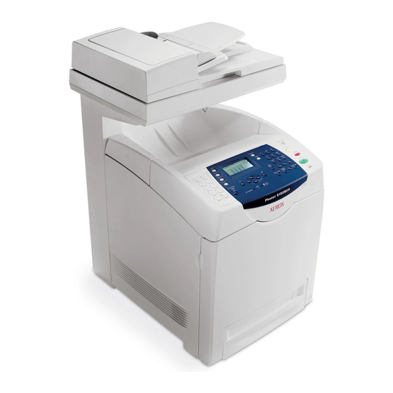
Page 39: Scanner
General Information Scanner s6180mfp-386 Automatic Document Feeder (ADF) Cover Document Guides Document Feed Tray Document Glass Scanner Lock Lever Phaser 6180MFP Multifunction Printer Service Manual... -
Page 40: Control Panel
Control Panel - Left Side The left side of the Control Panel contains One Touch Buttons. One Touch button – Provides access to the first 10 entries in the Fax address book. s6180mfp-380 Phaser 6180MFP Multifunction Printer Service Manual... - Page 41 Clear button – Deletes a single 16. Exit button – Moves up one level in character each time the button is the menu. pressed. For use when entering e- mail addresses and telephone numbers. Phaser 6180MFP Multifunction Printer Service Manual...
- Page 42 Buttons Pressed at Power On Enter Service Diagnostics Up + Down Arrow buttons Reset Password to 0000 Menu (used when the Control Panel menus are locked) Boot Controller Update Up + Down + OK buttons 1-10 Phaser 6180MFP Multifunction Printer Service Manual...
-
Page 43: Printer Options
General Information Printer Options Phaser 6180MFP Multifunction printer options include: Additional Memory (256 MB/ 512 MB/ 1GB) Optional 550-Sheet Feeder (Tray 3) Duplex Unit Multi-Protocol Network Card Additional Memory The printer features one slot that accepts 256 or 512 MB, or 1 GB of DDR2 DIMMs. -
Page 44: Multi-Protocol Network Card
General Information Multi-Protocol Network Card The Multi-Protocol Network Card provides additional protocols and security features including Netware, IPP, SMB, WINS, DDNS, SSL/HTTPS, and IPv6. s6180mfp-136 1-12 Phaser 6180MFP Multifunction Printer Service Manual... -
Page 45: Optional 550-Sheet Feeder (Tray 3)
The Optional 550-Sheet Feeder increases the input capacity of the printer and can be attached to the printer underneath Tray 2 with 2 thumb screws. The Optional 550-Sheet Feeder is customer installable. Note Only one Optional 550-Sheet Feeder is supported. s6180mfp-200 Phaser 6180MFP Multifunction Printer Service Manual 1-13... -
Page 46: Maintenance Items
Print life is based on “typical” office printing and 5% coverage per color on 24 lb. paper. The 100,000 life is not guaranteed and varies depending on usage habits. Fuser Transfer Unit Feed Rollers Tray 2 Tray 2 Retard Rollers s6180mfp-116 1-14 Phaser 6180MFP Multifunction Printer Service Manual... - Page 47 General Information Optional 550-Sheet Feeder Feed Roller Optional 550-Sheet Feeder Retard Roller s6180mfp-141 Phaser 6180MFP Multifunction Printer Service Manual 1-15...
-
Page 48: Consumables
Maintenance Items life usage. Life ratings are based on A-size sheets at 5% coverage. Print Cartridge Print Life Color Mono Standard Capacity 2,000 pages 3,000 pages High Capacity 6,000 pages 8,000 pages s6180mfp-137 1-16 Phaser 6180MFP Multifunction Printer Service Manual... -
Page 49: Specifications
Less than 30 seconds from power On Operating System Windows 2000/ 2003 Server/ XP Pro/ XP/ Vista Macintosh OS 10.2 or higher Linux Redhat, SuSe, and TurboLinux 10 Desktop * Assumes a 30 day month of printing. Phaser 6180MFP Multifunction Printer Service Manual 1-17... -
Page 50: Scanning Specifications
Up to 100 e-mail addresses & up to 10 e-mail group addresses stored in device memory. Each e-mail group may have up to 10 addresses associated with it. (Addresses stored in device memory.) 1-18 Phaser 6180MFP Multifunction Printer Service Manual... - Page 51 Manager) Network Scan to Document Glass, 150 dpi, 9 sec. 8 sec. Computer via SMB mixed, letter size Network Scan to E-mail Document Glass, 150 dpi, 9 sec. 10 sec. mixed, letter size Phaser 6180MFP Multifunction Printer Service Manual 1-19...
-
Page 52: Copy Specifications
Copy Speeds from Document Feeder (Simplex Output) 1st Copy, 1st Copy, 1st 1st Copy, 2nd & Subsequent Subsequent Mode Simplex Page 3rd Simplex Simplex Copies Simplex Pages (sec.) Pages (ppm) (ppm) (ppm) Mono Color 1-20 Phaser 6180MFP Multifunction Printer Service Manual... -
Page 53: Fax Specifications
PS driver - not support Color Not support Delayed Start Up to 24 hours Broadcast Sending Up to 30 destinations Zoom 25%-400% (same as printer driver) Auto Reduction/ On/Off (same as printer driver) Enlarge (Auto Fit) Phaser 6180MFP Multifunction Printer Service Manual 1-21... -
Page 54: Memory Specifications
15 to 80% RH Standby 5 to 85% RH Altitude Operating 0 to 3,100 meters (10,171 feet) Acoustic Noise Sound Power Level (Bels) Sound Pressure (Decibels) Printing 6.59 B 51.6 dB(A) Standby 4.18 B 26.8 dB(A) 1-22 Phaser 6180MFP Multifunction Printer Service Manual... -
Page 55: Electrical Specifications
Data and information are guaranteed for more than 5 years of accumulated power Off time under the condition where ambient temperature is 22° C. The battery is recyclable and does not cause fire or smoke. Phaser 6180MFP Multifunction Printer Service Manual 1-23... -
Page 56: Print Speed
Letter/B5/Executive Legal Custom Size Paper Type (105 - 162gsm) Letter A5/B5/Executive Legal Custom Size Paper Type (163 - 216gsm) Letter/A5/B5/Executive Legal Custom Transparencies, Envelopes, Cards Letter/A4 C5, D5, #10 Commercial Envelope Post Card 1-24 Phaser 6180MFP Multifunction Printer Service Manual... -
Page 57: Operating Mode
General Information Operating Mode The Phaser 6180MFP consists of the following operating modes: Running Mode: The Printer, Scanner, and Fax communication operates in the Print mode, Scan mode, and Fax mode respectively. More than one of these three modes can exist concurrently. - Page 58 Lamp Off Control Panel Back light off... LCD displays Ready. Power Saver LED is On. Press the Wake Up button to wake up the printer. Scanner Wake Up key function is provided. Controller 1-26 Phaser 6180MFP Multifunction Printer Service Manual...
- Page 59 Up part. Engine Fan Stopped NOTE The Deep Sleep mode is cancelled under the following conditions: Any button on the Control Panel is pressed A print job is started A Fax job is started Phaser 6180MFP Multifunction Printer Service Manual 1-27...
-
Page 60: Warm-Up Time
Paper is A size Short-Edge Feed (SEF). Document is on the document glass (Document setting: Platen mode). Media: Media feed from the standard media tray. Mode FCOT (sec.) Color As fast as 11.1 Mono As fast as 20.0 1-28 Phaser 6180MFP Multifunction Printer Service Manual... -
Page 61: Image Specifications
Vertical Duplex 234 mm (9.2 in.) ± 0.8 mm (.03 in.) Registration Leading Edge 10.0 mm (.40 in.) ± 2.0 mm (.08 in.) Side Edge 8.5 mm (.33 in.) ± 2.5 mm (.09 in.) Phaser 6180MFP Multifunction Printer Service Manual 1-29... -
Page 62: Alignment Specifications
Linearity (slant) ±2.1 mm ±2.9 mm ± 1.2 mm ±2.0 mm ±0.9 mm (200 mm) (±1.1 mm/ 254.5 mm conversion) Parallelism ±3.3 mm ±4.1 mm ±2.0 mm ±2.8 mm ±1.3 mm (280 mm) 1-30 Phaser 6180MFP Multifunction Printer Service Manual... -
Page 63: Physical Dimensions And Clearances
20.0 kg (44.0 lb.) Minimum Clearances 66 cm 122.0 cm (26.0 in.) (48.0 in.) 108 cm (42.5 in.) 10 cm 10 cm (4 in.) (4 in.) 10 cm (4 in.) 60 cm (23.6 in.) s6180mfp-115 Phaser 6180MFP Multifunction Printer Service Manual 1-31... -
Page 64: Mounting Surface Specifications
60 cm (23.6 in.) (23.6 in.) 10 cm (4.0 in.) 10 cm (4.0 in.) s6180mfp-138 Mounting surface flatness must be within the specified range. Right Hand Side 5 mm (2.0 in.) Max s6180mfp-139 1-32 Phaser 6180MFP Multifunction Printer Service Manual... - Page 65 Color-to-Color mis-registration, primarily in the horizontal (laser scan) direction. A smear or line of toner approximately 40 mm from the training edge of the print. Phaser 6180MFP Multifunction Printer Service Manual 1-33...
-
Page 66: Media And Tray Specifications
General Information Media and Tray Specifications The following tables list the recommended Xerox paper for the printer. Supported Paper Size Paper Type Dimension Tray 1 (MPT) Tray 2, 3 Letter 8.5 x 11 in. Legal 8.5 x 14 in. US Folio 8.5 x 13 in. - Page 67 4.12 x 9.5 in. Monarch Envelope 3.87 x 7.5 in. C5 Envelope 162 x 229 mm DL Envelope 110 x 220 mm Note: Do not use envelopes with hot melt glue, windows, or metal clasps. Phaser 6180MFP Multifunction Printer Service Manual 1-35...
-
Page 68: Controller Functions
Time-out setting can be changed and unlimited time can be selected using the menu on the printer’s Control Panel. Print Volume Management Print Volume (PV) Management manages print volume per user and can manage up to 50 users. 1-36 Phaser 6180MFP Multifunction Printer Service Manual... - Page 69 Off. This function is not available for Mac OS 10.2 and Linux operating systems. Phaser 6180MFP Multifunction Printer Service Manual 1-37...
-
Page 70: Id Print
This mode can be changed so the printer will not stop at the end of the print cartridge rated life; however, the printer will display an end of life message on the Control Panel. 1-38 Phaser 6180MFP Multifunction Printer Service Manual... -
Page 71: Toner Remaining Amount
Via Network (port 9100) Image Processor Board Available Available Multi-Protocol Network Card Available Available MCU Board* Available Available * MCU Board cannot be updated when ROM starts to be used for MCU Board. Phaser 6180MFP Multifunction Printer Service Manual 1-39... -
Page 72: Diagnostics
Service Mode in the Control Panel. Information Pages Demo Page Demo Page provides sample print for the Phaser 6180MFP Multifunction Printer. The Demo Page is printed in color from the selected paper tray. 1-40 Phaser 6180MFP Multifunction Printer Service Manual... - Page 73 > Configuration. The Configuration Page is printed from the default tray which contains the following information. Configuration Page Information General Description Detail Description Title Prints Title of the document Product Name (Logo) Prints organization’s logo Phaser 6180MFP Multifunction Printer Service Manual 1-41...
- Page 74 Quantity, Image Enhance, Hex Dump, Draft Mode, Line Termination, Default Color PostScript PS Error Report, PS Job Time-Out, Paper Select Mode Secure Settings Panel Lock, Scan/Fax Lock, Secure Receive Lock Tray Settings Tray 1 (MPT), Tray 2 1-42 Phaser 6180MFP Multifunction Printer Service Manual...
- Page 75 User can print the PostScript Fonts List default on A size paper from default tray. The PostScript Fonts List contains: Print Fonts, Fonts Sample Stored Documents List The Stored Documents report provides list of Secure Print and Proof Print jobs. Phaser 6180MFP Multifunction Printer Service Manual 1-43...
- Page 76 Time passed Facsimile information field: Facsimile control field: since the Information regarding the 8bit information that communication content of each signal. identifies each signal started. s6180mfp-430 by type. 1-44 Phaser 6180MFP Multifunction Printer Service Manual...
- Page 77 The Job History Report contains: Job sent data and time Input Port (Port 9100, USB,...etc.) Host/User Name Document Name (File Name) Default Color Paper Size Pages Sheets Result (completed, error,...etc.) s6180mfp-384 Phaser 6180MFP Multifunction Printer Service Manual 1-45...
- Page 78 Control Panel. The Error History Report contains the following information: System Fail History – Item No., Total Print Count, Chain-Link Paper Jam History Item No. – Item No., Total Print Count, Paper Jam Type 1-46 Phaser 6180MFP Multifunction Printer Service Manual...
-
Page 79: Admin Reports
The Server Address report provides a list of servers connected to the printer. Fax Pending Report The Fax Pending report provides a list of pending fax jobs that has been stored in the memory. Phaser 6180MFP Multifunction Printer Service Manual 1-47... - Page 80 50 jobs. This report is automatically printed when sent/received faxes exceeds 50 jobs. The report can also be printed via the Control Panel menu. This can indicate send mode is OK. Can monitor the status history or errors. s6180mfp-429 1-48 Phaser 6180MFP Multifunction Printer Service Manual...
- Page 81 Print Meter (Print Volume Report) User can print the Print Meter page on A paper size from default tray. The Print Meter page contains: Date of Initialization, Job Accounting User Name, Pages, Sheets, Date/ Time s6180mfp-385 Phaser 6180MFP Multifunction Printer Service Manual 1-49...
- Page 82 General Information 1-50 Phaser 6180MFP Multifunction Printer Service Manual...
-
Page 83: Theory Of Operation
Theory of Operation In this chapter... Phaser 6180MFP Operational Overview Printing Process Paper Path of the Printer Major Assemblies and Functions Printer Modes Printer Control Drive Transmission Optional 550-Sheet Feeder Drive Scanner Assembly Fax System Chapter... -
Page 84: Phaser 6180Mfp Operational Overview
Theory of Operation Phaser 6180MFP Operational Overview The Phaser 6180MFP is a full-color laser printer that uses Raster Output Scanner (ROS) lasers with an electrophotographic four-color CMYK process. The tandem system consists of four color print cartridges (C, M, Y, and K) which creates the toner image. - Page 85 NCU, and sends the data to the Printer Controller. Automatic Document Feeder Scanner Assembly Lamp (Inverter) Sensor Motor Print Engine Control Panel Network Scanner Control PSTN/PBX Controller Unit Network Laser Printer IEEE 1264 Unit Controller s6180mfp-424 Phaser 6180MFP Multifunction Printer Service Manual...
-
Page 86: Print Process Block Diagram
Theory of Operation Print Process Block Diagram The following block diagram provides the sequence of events for the xerographic process (dashed lines) and the paper flow (solid lines) into and out of the Phaser 6180MFP. Phaser 6180MFP Multifunction Printer Service Manual... -
Page 87: Printing Process
Theory of Operation Printing Process The Phaser 6180MFP print process consists of the following steps: Charging – The Drum surfaces are charged with electricity. Exposure – The Drums are exposed to laser beams. Development – Image is developed with toner. -
Page 88: Charging
The Drum surface is a photoreceptor (which is an insulator in a dark area and a conductor when receiving light) and the Drum inside is composed of conductor. The BCR Cleaner contacts with the BCR to catch the toner. Photoreceptor Conductor Cleaning Roll Drum HVPS s6180mfp-030 Phaser 6180MFP Multifunction Printer Service Manual... -
Page 89: Exposure
Polygon Mirror Laser Beam (C) Laser Beam (M) Laser Beam (Y) Mirror Drum (K) Mirror Mirror Mirror Drum (C) Mirror Mirror Drum (M) Lens Lens Mirror Drum (Y) Polygon Mirror Mirror Mirror Mirror s6180mfp-031 Phaser 6180MFP Multifunction Printer Service Manual... - Page 90 Negative Electric Charge Positive Electric Charge Photoreceptor Conductor Laser Beams Drum Surface Drum Laser Beam Electrostatic Latent Image Concept of Drum Electrostatic Potential on Laser Beam Latent Image Drum Surface Laser Beam Photoreceptor Conductor s6180mfp-032 Phaser 6180MFP Multifunction Printer Service Manual...
-
Page 91: Development
Trimmer Bar as the carrier magnetic substance is attracted to the Magnetic Roll. Negative Electric Charge Positive Electric Charge Toner Carrier Developer Print Cartridge Trimmer Bar Waste Toner Collecting Area Drum Magnet Roll HVPS Auger Agitator s6180mfp-033 Phaser 6180MFP Multifunction Printer Service Manual... - Page 92 Electric Potential Drum Surface on Drum Developing Bias Toner Image s6180mfp-183 2-10 Phaser 6180MFP Multifunction Printer Service Manual...
-
Page 93: Transfer (Drum
Drum Surface (Black Toner Image) Drum Surface (Cyan Toner Image) Paper Black Toner Image Cyan Toner Image Drum Surface Magenta (Magenta Toner Image) Toner Image Yellow Toner Image Drum Surface (Yellow Toner Image) s6180mfp-035 Phaser 6180MFP Multifunction Printer Service Manual 2-11... - Page 94 HVPS and discharges to the paper to improve the toner transfer efficiency. Negative Electric Charge Paper Postive Electric Charge Toner Drum (K) Drum (C) Drum Surface Drum (M) Drum (Y) HVPS HVPS ESA Roll Transfer Unit s6180mfp-034 2-12 Phaser 6180MFP Multifunction Printer Service Manual...
-
Page 95: Cleaning (Print Cartridge)
The excess charge on the surface of the Drum is eliminated by irradiating light of the Erase Lamp (LED). Positive Electric Charge Erase Lamp (LED) Negative Electric Charge Toner Blade Conductor Drum Photoreceptor Cleaning Roll BCR s6180mfp-036 Phaser 6180MFP Multifunction Printer Service Manual 2-13... -
Page 96: Neutralization
Negative Electric Charge Paper Positive Electric Charge Detack Saw Drum Detack Saw Drum Detack Saw Drum Detack Saw Drum HVPS Transfer Unit s6180mfp-037 2-14 Phaser 6180MFP Multifunction Printer Service Manual... -
Page 97: Fusing
A cleaning blade in the Print Cartridge scrapes off toner remaining on the drum surface after transfer has occurred. Then, the latent charge pattern remaining on the photoconductive drum is neutralized by the Erase Lamp to prepare the drum for the next Exposure cycle. Phaser 6180MFP Multifunction Printer Service Manual 2-15... -
Page 98: Paper Path Of The Printer
Registration Motor Drive/ Clutch/Regi Roll Transfer Unit Motor Drive/Belt Fuser Motor Drive/Heat Roll/ Pressure Belt Exit Roll in the Fuser Motor Drive/Clutch/ Exit Roll Duplex Module Output Tray Motor Drive/Clutch/ Dup Roll s6180mfp-039 2-16 Phaser 6180MFP Multifunction Printer Service Manual... -
Page 99: Paper Path Components
Tray 1 (MPT) No Paper Sensor Turn Roller (550-Sheet Feed Roller Feeder) (250-Sheet Feeder) Feed Roller Tray 2 Retard Roller (550-Sheet Feeder) (250-Sheet Feeder) Turn Roller Tray 3 Retard Roller (550-Sheet Feeder) (550-Sheet Feeder) s6180mfp-040 Phaser 6180MFP Multifunction Printer Service Manual 2-17... -
Page 100: Major Assemblies And Functions
Tray 2 End Guide Left Side Guide Right Side Guide Retard Roller s6180mfp-041 Tray 2 Left/Right Side Guide The Side Guides move at a right angle toward the paper transfer direction to align the paper width. 2-18 Phaser 6180MFP Multifunction Printer Service Manual... - Page 101 Bottom Lock Oneway Gear Rear of Tray Front of Tray Bottom Lock Lever Support Nudger Bottom Rack Lock Bottom Lock Lever Gear Left Guide Bottom Lock Oneway Gear Stopper Actuator Lock Part (Tray Housing) Stopper s6180mfp-043 Phaser 6180MFP Multifunction Printer Service Manual 2-19...
- Page 102 Feed Roller and Retard Roller rotate to allow the sheet to pass. Feed Roller (Takeaway Roller) Single Feed Feed Roller (Nudger Roller) Retard Roller (Separator) Friction Clutch Retard Roller (Separator) s6180mfp-085 2-20 Phaser 6180MFP Multifunction Printer Service Manual...
- Page 103 The Retard Roller is pushed toward the Feed Roller by spring pressure, and controlled by the Friction Clutch with which it is coupled. Feed Roller (Takeaway Roller) Multiple Feed Feed Roller (Nudger Roller) Retard Roller (Separator) Friction Clutch Retard Roller (Separator) s6180mfp-042 Phaser 6180MFP Multifunction Printer Service Manual 2-21...
-
Page 104: Paper Feeder
Tray 2 Feed Roller The Feed Roller (Takeaway Roller) feeds the paper when the Feed Clutch operates. Tray 2 Feed Clutch The Feed Clutch transmits drive energy from the Drive Assembly to the Feed Roller. 2-22 Phaser 6180MFP Multifunction Printer Service Manual... - Page 105 Legal 14" (SEF) A4 (SEF) Legal 13" (SEF) All paper should be loaded SEF. s6180mfp-044 Note Refer to “Paper Size Detection” on page 2-56 for detailed information on paper size switches and paper size. Phaser 6180MFP Multifunction Printer Service Manual 2-23...
- Page 106 The No Paper Sensor detects the presence of the paper in the tray based on the Tray 2 No Paper Actuator position. No Paper Sensor No Paper Actuator Actuator (No Paper Position) s6180mfp-046 2-24 Phaser 6180MFP Multifunction Printer Service Manual...
-
Page 107: Tray 1 (Mpt) & Registration
Registration Chute. When paper is fed from Tray 1 (MPT), the Registration Sensor measures the paper length. The On time of the Registration Sensor is converted into the paper length. Note On: The paper activates the Actuator. Phaser 6180MFP Multifunction Printer Service Manual 2-25... - Page 108 Tray 1 (MPT) Feed Solenoid The Feed Solenoid controls drive energy from the Drive Assembly to the Tray 1 (MPT) Feed Roller. Tray 1 (MPT) Feed Roller Tray 1 (MPT) Feed Solenoid Retard Roller Drive Assembly s6180mfp-048 2-26 Phaser 6180MFP Multifunction Printer Service Manual...
- Page 109 Normally, when only one sheet is fed, both the Feed Roller and Retard Roller rotate to allow the sheet to pass. Tray 1 (MPT) Feed Roller Torque Limiter Retard Roller Retard Roller Single Feed s6180mfp-086 Phaser 6180MFP Multifunction Printer Service Manual 2-27...
- Page 110 The Retard Roller is pushed toward the Feed Roller by spring pressure, and controlled by the Torque Limiter (Friction Clutch Retard) with which it is coupled. Tray 1 (MPT) Feed Roller Multiple Feed Torque Limiter Retard Roller Retard Roller s6180mfp-050 2-28 Phaser 6180MFP Multifunction Printer Service Manual...
- Page 111 By pushing the edge of the sheet coming out of Tray 1 (MPT) against the Registration Roller that is not turning, the lead edge of the sheet is registered. Registration Rollers Skewed Paper s6180mfp-052 Phaser 6180MFP Multifunction Printer Service Manual 2-29...
- Page 112 Registration Sensor Spring (A) Normal Position From Tray 1 (MPT) or Duplex Registration Registration Sensor Sensor Paper Actuator A Actuator A Actuator B Registration From Paper Tray Sensor Paper Actuator A Actuator B s6180mfp-053 2-30 Phaser 6180MFP Multifunction Printer Service Manual...
-
Page 113: Fuser Unit
The Heat Roller is a metal tube with coated surface and a Heater inside. As the paper passes between the Heat Roller and Pressure Belt, heat that is applied to the paper, melts the toner, and fuses it to the paper. Phaser 6180MFP Multifunction Printer Service Manual 2-31... - Page 114 Heat Roller. The pressure bonds the melted toner to the paper. Exit Roller The Exit Roller transports paper from the Fuser to the output tray. Exit Sensor The Exit Sensor detects passage of printed pages after fusing on the Actuator’s position changes. 2-32 Phaser 6180MFP Multifunction Printer Service Manual...
-
Page 115: Transfer Unit
On, the ADC Solenoid activates the ADC Pad, which cleans contamination on the ADC Sensor surface. ESA Roller The ESA Roller discharges a positive voltage to the paper. Toner transfer efficiency is raised by applying a positive charge to the paper. Phaser 6180MFP Multifunction Printer Service Manual 2-33... -
Page 116: Laser Unit
The Laser Unit is an exposure unit that generates laser beams to form electrostatic latent image on the drum surface. The Laser Unit consists of the following components: Laser Diode (LD), Scanner, Start of Scan (SOS) Board, Lenses, Mirror, and Window. 2-34 Phaser 6180MFP Multifunction Printer Service Manual... - Page 117 Lenses, Mirror, and Window. The Lenses correct aberration. Mirror The Mirror directs the laser beam and secure an optical path. Window The window prevents debris from entering into the Laser Unit. Phaser 6180MFP Multifunction Printer Service Manual 2-35...
-
Page 118: Print Cartridge
Black. Print Life for the Print Cartridges are: Standard Capacity: 2,000 pages for color print, and 3,000 pages for black & white prints High Capacity: 6,000 pages for color prints, and 8,000 pages for black & white prints 2-36 Phaser 6180MFP Multifunction Printer Service Manual... - Page 119 Erase Lamp (LED) The light of the LED passes through the lens of the Print Cartridge, illuminates the Drum, and eliminates the charge on the Drum. Erase Lens Erase Lamp Drum Print Cartridge s6180mfp-056 Phaser 6180MFP Multifunction Printer Service Manual 2-37...
-
Page 120: Main Drive
Fuser. Sub Motor The Sub Motor provides drive energy for the Black Developer, Cyan, Magenta, and Yellow Drums. Developer Motor The Developer Motor provides drive energy for the Cyan, Magenta, and Yellow Developers. 2-38 Phaser 6180MFP Multifunction Printer Service Manual... - Page 121 The Drive Assembly provides drive energy for Tray 1 (MPT), Tray 2, and Registration. The Tray 2 Motor is part of the Drive Assembly. Note Refer to “Mechanical Components” on page 2-62 for detailed diagrams. Phaser 6180MFP Multifunction Printer Service Manual 2-39...
-
Page 122: Electrical
Theory of Operation Electrical Switches, Sensor, and Boards Interlock Switch Humidity/Temperature Sensor s6180mfp-150 Main Fan Control Panel HVPS Power Switch EEPROM Board Humidity/Temperature Sensor Interlock Switch s6180mfp-149 2-40 Phaser 6180MFP Multifunction Printer Service Manual... - Page 123 The Control Panel displays the machine status and operates the printer/ scanner/copier/fax. Power Saver Copy Job Status @:./ System Clear All E-mail PQRS WXYZ Stop Scan Color Mode Start B&W Redial/ Color Manual Dial Speed Dial Pause Job in Memory Error s6180mfp-133 Phaser 6180MFP Multifunction Printer Service Manual 2-41...
- Page 124 Heater; the LVPS also generates and supplies stable low-voltage DC power used for the logic circuit. The LVPS contains a control circuit for the heater of the Fuser, in addition to the power circuit. s6180mfp-374 2-42 Phaser 6180MFP Multifunction Printer Service Manual...
- Page 125 The High-Voltage Power Supply (HVPS) provides high-voltage power to the components in the Transfer Unit and Print Cartridge to perform charging, development, and primary transfer of the print process to the BCR, BTR, Developer, and ESA Roller. s6180mfp-152 Phaser 6180MFP Multifunction Printer Service Manual 2-43...
- Page 126 Diagnostic, Interface, and Image Processing. The I/P Board is one of the major elements of the Phaser 6180MFP. The primary function of the I/P Board is to receive host data through one of the following available ports (Parallel, USB, or Ethernet). The received host data is buffered, stored, and sent to the print engine in a rasterized format.
- Page 127 Distributes low-voltage DC power generated from the LVPS to each component. Controls the Laser Unit. NVRAM s6180mfp-154 Note When replacing an MCU Board, be sure to transfer the NVRAM from the old MCU Board to the new MCU Board. Phaser 6180MFP Multifunction Printer Service Manual 2-45...
- Page 128 Scanner Controller Board for further processing. Outgoing fax data is passed from the Scanner Controller Board at the appropriate timing sequence when a clear transmission line has been established. s6180mfp-426 2-46 Phaser 6180MFP Multifunction Printer Service Manual...
- Page 129 Laser Unit (Laser Beams) Laser Unit Print Electrostatic Latent On Cartridges (4x) Drum (Invisible Image) Print Toner Image On Drum Cartridges (4x) Toner Image On Paper Transfer Unit Fuser Print Image On Paper s6180mfp-057 Phaser 6180MFP Multifunction Printer Service Manual 2-47...
-
Page 130: Duplex Unit
Roller), Upper Roller (Duplex 1 Roller), and Exit Roller on the Fuser. Duplex Board The Duplex Board controls the Motor, Sensor, and Clutch. Duplex Fan The Duplex Fan removes heat from inside of the printer to prevent overheating. 2-48 Phaser 6180MFP Multifunction Printer Service Manual... -
Page 131: Tray 3 - Optional 550-Sheet Feeder
The On/Off of the Size Switches adjust according to the Tray 3 End Guide position to detect the paper size. Tray 3 Retard Roller The Retard Roller and the Feed Roller (Pick Up Unit) pinch the paper to feed. Phaser 6180MFP Multifunction Printer Service Manual 2-49... - Page 132 Bottom Lock Oneway Gear Rear of Tray Front of Tray Bottom Lock Lever Support Nudger Bottom Rack Lock Bottom Lock Lever Gear Left Guide Bottom Lock Oneway Gear Stopper Actuator Lock Part (Tray Housing) Stopper s6180mfp-059 2-50 Phaser 6180MFP Multifunction Printer Service Manual...
- Page 133 Optional 550-Sheet Feeder Drive The Optional 550-Sheet Feeder Drive drives the rollers of the Optional Feeder. Optional 550-Sheet Feeder Board The Optional 550-Sheet Feeder Board controls the Motor, Sensor, and Clutch. Phaser 6180MFP Multifunction Printer Service Manual 2-51...
- Page 134 Letter (SEF) Legal 14" (SEF) Legal 13" (SEF) All paper should be loaded SEF. s6180mfp-156 Note Refer to “Paper Size Detection” on page 2-56 for detailed information on paper size switches and paper size. 2-52 Phaser 6180MFP Multifunction Printer Service Manual...
- Page 135 Feed Roller and Retard Roller rotate to allow the sheet to pass. Feed Roller (Takeaway Roller) Single Feed Feed Roller (Nudger Roller) Retard Roller (Separator) Friction Clutch Retard Roller (Separator) s6180mfp-085 Phaser 6180MFP Multifunction Printer Service Manual 2-53...
- Page 136 The Retard Roller is pushed toward Feed Roller by spring pressure, and controlled by the Friction Clutch with which it is coupled. Feed Roller (Takeaway Roller) Multiple Feed Feed Roller (Nudger Roller) Retard Roller (Separator) Friction Clutch Retard Roller (Separator) s6180mfp-042 2-54 Phaser 6180MFP Multifunction Printer Service Manual...
-
Page 137: Printer Modes
Printing Feed Jam Occurred Error Life Over s6180mfp-061 The Phaser 6180MFP includes the following modes: Diagnostics Mode The printer is ready to receive diagnostic commands, or the printer diagnostic function is operating. Wait Mode The printer is preforming Print Quality adjustment. -
Page 138: Printer Control
Letter (SEF) A4 (SEF) B5 (SEF) Legal 13” (SEF) Legal 14” (SEF) Executive (SEF) No Tray Note On: The Actuator is pushing the Size Switch. Switch 1 Switch 2 Switch 3 Size Switch s6180mfp-062 2-56 Phaser 6180MFP Multifunction Printer Service Manual... -
Page 139: Selective Control On Paper Tray
The patches of respective colors (Yellow, Magenta, Cyan, and Black) for the potential control are generated and transferred on the Transfer Belt. The ADC Sensor (Density Sensor) detects the density of the patch on the Belt. Phaser 6180MFP Multifunction Printer Service Manual 2-57... - Page 140 ADC Sensor falls far below the standard value, by dispensing extra toner. If the toner density level cannot be recovered after this operation, it is determined that toner has run out. 2-58 Phaser 6180MFP Multifunction Printer Service Manual...
- Page 141 ADC Sensor for the specified range. If the output value is low, the light intensity is increased by the specified amount at the next ADC, or if high, the light intensity is reduced at the next ADC. Phaser 6180MFP Multifunction Printer Service Manual 2-59...
-
Page 142: Color Registration Control
The adjusting amount of registration shift is calculated from the threshold value determined in step 1 and the patch density measured in step 3. The Laser Unit write timing is changed from the adjusting amount of registration shift. 2-60 Phaser 6180MFP Multifunction Printer Service Manual... -
Page 143: Fuser Control
Sensor itself is below -5° C. Therefore, the Sensor will be warmed up when the temperature is below -5° C. This process is called Sensor Warm-Up. Phaser 6180MFP Multifunction Printer Service Manual 2-61... -
Page 144: Drive Transmission
Gear stops rotating. The Clutch makes very soft noise. When verifying the Clutch operation, ensure to stay close to the component in order to hear the sound. Shaft Case Coil Rotor Armature Gear s6180mfp-083 2-62 Phaser 6180MFP Multifunction Printer Service Manual... - Page 145 On the basis of whether or not the light path is blocked due to the actuator, etc., the sensor detects the paper absence/ presence or the moving parts position such as at the home position or elsewhere. Actuator Optic Sensor/Actuator Phaser 6180MFP Multifunction Printer Service Manual 2-63...
- Page 146 When the door or cover is opened, the leaf spring returns to its original position and the button is pushed up by the spring in the Switch, allowing the internal contacts to open. Actuator Button Blade Contact 2-64 Phaser 6180MFP Multifunction Printer Service Manual...
-
Page 147: Main Drive
Print Cartridge (M) Print Cartridge (Y) Magnet Roller Gear (K) Developer Idler Gear (K) Auger Gear (K) Auger Gear (K) [Magnet Roller (K)] [Supply Auger (K)] [Admix Auger (K)] Print Cartridge (K) s6180mfp-065 Phaser 6180MFP Multifunction Printer Service Manual 2-65... -
Page 148: Front View
Drum Gear (K) [Supply Auger (K)] [Drum (K)] Auger Gear (K) [Admix Auger (K)] Drum Gear (C) [Drum (C)] Drum Gear (M) [Drum (M)] Sub Motor Drum Gear (Y) [Drum (Y)] Front s6180mfp-066 2-66 Phaser 6180MFP Multifunction Printer Service Manual... - Page 149 [Supply Auger (M)] [Supply Auger (Y)] Auger Gear (C) Auger Gear (M) Auger Gear (Y) [Admix Auger (C)] [Admix Auger (M)] [Admix Auger (Y)] Print Cartridge (Y) Print Cartridge (C) Print Cartridge (M) s6180mfp-067 Phaser 6180MFP Multifunction Printer Service Manual 2-67...
- Page 150 Auger Gear (M) Drum Gear (Y) [Supply Auger (M)] [Drum (Y)] Magnet Roller Gear (Y) Front [Magnet Roller (Y)] Developer Idler Gear (Y) Auger Gear (Y) Auger Gear(Y) [Supply Auger (Y)] [Admix Auger (Y)] s6180mfp-068 2-68 Phaser 6180MFP Multifunction Printer Service Manual...
- Page 151 Duplex Idler Gear 1 Duplex Idler Gear 2 [Exit Roller] [Heat Roller] [Name of Moving Parts] Fuser Duplex Gear 25Z Duplex Gear 21Z 25Z Duplex Idler Gear 21Z Duplex Clutch Duplex Module s6180mfp-069 Phaser 6180MFP Multifunction Printer Service Manual 2-69...
- Page 152 Exit Idler Gear 6 Duplex Idler Heat Roller Gear 21Z Idler Gear Duplex Main Drive Clutch Duplex Module Front Main Motor Exit Clutch Heat Roller Gear [Heat Roller] [Name of Moving Parts] s6180mfp-070 2-70 Phaser 6180MFP Multifunction Printer Service Manual...
-
Page 153: Dispenser (C) (M) (Y) (K)
Main Developer Main Developer Agitator Gear Agitator Gear Dispenser Idler Gear 1 [Front Main Agitator] [Rear Main Agitator] Dispenser Gear [Name of Moving Parts] [Dispenser Auger] Print Cartridge (C) (M) (Y) (K) s6180mfp-071 Phaser 6180MFP Multifunction Printer Service Manual 2-71... - Page 154 Dispenser Idler Gear 1 Dispenser Gear Print Cartridge [Dispenser Auger] (C) (M) (Y) (K) Main Developer Agitator Gear [Front Main Agitator] Dispenser Idler Gear 1 Main Developer Agitator Gear [Rear Main Agitator] s6180mfp-072 2-72 Phaser 6180MFP Multifunction Printer Service Manual...
-
Page 155: Drive Assembly
Registration Clutch Feed Clutch Oneway Nudger Clutch [Turn Roller] [Rubber Registration Roller] Rubber Registration Gear [Feed Roller] Metal Registration Gear Nudger Idler Gear Nudger Roller Gear [Metal Registration Roller] [Feed Roller] Feeder s6180mfp-073 Phaser 6180MFP Multifunction Printer Service Manual 2-73... - Page 156 Feed Clutch Feed Solenoid Tray 1 (MPT) Gear [Tray 1 (MPT) Roller] Nudger Roller Front Gear [Feed Roller] Nudger Idler Gear Drive Assembly Oneway Nudger Clutch [Name of Moving Parts] [Feed Roller] s6180mfp-074 2-74 Phaser 6180MFP Multifunction Printer Service Manual...
-
Page 157: Duplex Drive
Duplex Clutch Exit Gear Exit Idler Gear 5 Duplex Idler Gear 21Z Exit Idler Gear 6 [Exit Roller] Duplex Gear 21Z 25Z Exit Clutch [Name of Moving Parts] Duplex Gear 25Z Main Drive s6180mfp-075 Phaser 6180MFP Multifunction Printer Service Manual 2-75... - Page 158 Exit Idler Gear 5 Exit Idler Gear 6 Duplex Idler Gear 21Z Duplex Clutch [Duplex Roller 1] Main Drive Duplex Module Exit Clutch [Duplex Belt] Duplex Motor Duplex Gear 40Z [Duplex Roller 2] Front s6180mfp-076 2-76 Phaser 6180MFP Multifunction Printer Service Manual...
-
Page 159: Optional 550-Sheet Feeder Drive
Optional Turn Clutch [Turn Roller] Oneway Nudger Clutch [Optional 550-Sheet Feeder Tray Feed Roller] Nudger Idler Gear Nudger Roller Gear [Optional 550-Sheet Feeder Tray Feed Roller] Optional 550-Sheet Feeder [Name of Moving Parts] 6180mfp-077 Phaser 6180MFP Multifunction Printer Service Manual 2-77... - Page 160 Optional Feeder Drive [Name of Moving Parts] Optional Turn Clutch [Turn Roller] Feed Clutch Nudger Roller Gear [Optional 550-Sheet Feeder Front Tray Feed Roller] Oneway Nudger Clutch Nudger Idler Gear [Optional 550-Sheet Feeder] s6180mfp-078 2-78 Phaser 6180MFP Multifunction Printer Service Manual...
-
Page 161: Scanner Assembly
Scanner Assembly: Exposure Lamp that illuminates light onto the document, CCD Image Sensor that reads light reflected from the document, and Lenses and mirrors comprising the light path for the optical image. Phaser 6180MFP Multifunction Printer Service Manual 2-79... -
Page 162: Scanning At Automatic Document Feeder
The Nudger Roller moves down with normal rotation of the ADF Motor. Upon completion of media feed, the ADF Motor reverses rotation to return the Nudger Roller to its normal position. 2-80 Phaser 6180MFP Multifunction Printer Service Manual... - Page 163 ADF Separator Pad, feeds the media (coming from the Nudger Roller) one by one. When the Feed Sensor detects the media, the printer recognizes that first media feeding is complete. Feed Sensor Feed Roller Nudger Roller Takeaway Roller ADF Separator Pad s6180mfp-090 Phaser 6180MFP Multifunction Printer Service Manual 2-81...
-
Page 164: Preregistration
When the media passes the CVT position at the specified speed, the images on the media are exposed by scanning with the Exposure Lamp of the Scanner Assembly, and read by the CCD Image Sensor. 2-82 Phaser 6180MFP Multifunction Printer Service Manual... - Page 165 The image data from the media set on the Scanner or ADF goes through the following components before it is printed at the Engine section. Media CCD Image Sensor (Scanner Assy) Scanner Engine Scanner Controller Board Controller (Image Processor Board) Laser Unit Drum (CRU) s6180mfp-095 Phaser 6180MFP Multifunction Printer Service Manual 2-83...
-
Page 166: Drive Torque Transfer
Gear C / Takeaway Roller Belt Gear D Regi Roller Exit Roller Gear G Oneway Clutch Gear H Gear I Friction Clutch Feed Roller Gear J Gear K Gear L Nudger Roller s6180mfp-098 2-84 Phaser 6180MFP Multifunction Printer Service Manual... - Page 167 Gear G Gear L Gear D Gear H Gear E Gear F Oneway Gear J Clutch Gear B Feed Roller (ADF Feed Roller) Exit Roller Belt Gear C Registration Roller Takeaway Roller s6180mfp-093 Phaser 6180MFP Multifunction Printer Service Manual 2-85...
-
Page 168: Functions Of Components
Scanner Home Position Sensor, thus detecting the Registration position. Cold Cathode Fluorescent Lamp (Exposure Lamp) The Cold Cathode Fluorescent Lamp exposes the document. Charged Coupled Device Board The Charged Coupled Device (CCD) Board (Image Sensor) converts optical images into electrical signals. 2-86 Phaser 6180MFP Multifunction Printer Service Manual... - Page 169 Registration Roller, thereby determining the next document feed can be started. Document Present: Shielded (blocked) Document Absent: Unshielded (unblocked) ADF Motor The ADF Motor rotates the Nudger Roller, Feed Roller, Takeaway Roller, Registration Roller, and Exit Roller. Phaser 6180MFP Multifunction Printer Service Manual 2-87...
-
Page 170: Control
Shading compensation compensates for pixel-by-pixel sensitivity variations and the non-uniformity of lamp light in the fast scanning direction. The AGC and AOC adjustment values are used to compensate for the image data read by the CCD Image Sensor. 2-88 Phaser 6180MFP Multifunction Printer Service Manual... -
Page 171: Ccd Image Sensor Overview
R G B Sensor Signal Sensor/Lamp Y M C K Switch Signal Control Panel Message Signal/ Controller Drive Signal Switch/Display/LED Switch Printer Status Image Signal Signal Image Processor Board Status Command MCU Board Printer s6180mfp-097 Phaser 6180MFP Multifunction Printer Service Manual 2-89... -
Page 172: Fax System
Both the microphone and speaker utilize this process. The microphone transduces sound into electrical signals using electromagnetic induction that occurs as a moving coil coupled to a diaphragm picking up sound wave. 2-90 Phaser 6180MFP Multifunction Printer Service Manual... - Page 173 Magnet (N Polarity) Magnet (S Polarity) a. The coil in the magnetic field is vibrated. The magnetic field around the coil is altered. b. An electric current (alternating current) is generated in the coil. s6180mfp-099 Phaser 6180MFP Multifunction Printer Service Manual 2-91...
- Page 174 The signal is converted to 1 or 0 depending on whether it is higher or lower than a threshold value. In other words, the waveform is quantified. Higher = 1 Threshold Lower = 0 Value Time Digital signal Time s6180mfp-100 2-92 Phaser 6180MFP Multifunction Printer Service Manual...
- Page 175 Fax communications that use an analog telephone network perform DA conversion before transmitting the scanned image from the phone, and AD conversion before printing the received data. Phaser 6180MFP Multifunction Printer Service Manual 2-93...
-
Page 176: Telephone Call Connection Mechanism
Subscriber line Transmission route Subscriber line s6180mfp-101 Switching Equipment Network Tandem Switch Telephone Set Local Switch Local Switch Tandem Switch Telephone Set Tandem Switch Local Switch Local Switch Telephone Set Telephone Set s6180mfp-102 2-94 Phaser 6180MFP Multifunction Printer Service Manual... - Page 177 Pulse Dialing & Tone Dialing Pulse Dialing "3, 5, .." 5 ..Switch Tone Dialing "3, 5, 2, .." 2 ..Switch DTMF Matrix 697Hz 770Hz Frequency 852Hz 941Hz 1209Hz 1336Hz 1447Hz High Frequency s6180mfp-103 Phaser 6180MFP Multifunction Printer Service Manual 2-95...
- Page 178 Dial the Number 3) Lines Are Automatically Connected. Connection 2) Phone Established Number c. Calling 4) Ringing Signal 4) Ring Back Tone d. Line Established Hello Hello 5) Response Signal Communications Path is Established. s6180mfp-104 2-96 Phaser 6180MFP Multifunction Printer Service Manual...
-
Page 179: Fax (Facsimile) System Overview
Fax System (Overview) Image Scanner Control Circuit Control Circuit Printer Telephone Line Scanning Printing Conversion Conversion Original Printing Digital Signal Analog Signal Digital Signal s6180mfp-105 Phaser 6180MFP Multifunction Printer Service Manual 2-97... - Page 180 (modulator/demodulator) in the control circuit. A modem consists of a Network Control Unit (NCU) for connecting to the telephone line and an A/D conversion unit for performing DA and AD conversions. 2-98 Phaser 6180MFP Multifunction Printer Service Manual...
- Page 181 When a connection between local switches is established, the local switch of the called party sends a ringing signal to the telephone of the called party. The telephone that receives the ringing signal emits its ringtone. At Phaser 6180MFP Multifunction Printer Service Manual 2-99...
- Page 182 The printer prints image data from the control circuit onto the surface of paper. The principle is the same as that of an ordinary printer in that black is applied to specified locations on the paper. 2-100 Phaser 6180MFP Multifunction Printer Service Manual...
-
Page 183: Protocol Monitor
The following flow chart provides a typical G3 fax session of a one-page document. Sending Fax Station Receiving Fax Station Phase A NSF/CSI/DIS (NSS)/TSI/DCS Phase B Training Signal Phase C PIX (Image Data) Phase D Phase E s6180mfp-431 Phaser 6180MFP Multifunction Printer Service Manual 2-101... - Page 184 Therefore, the session may show a looped sequence such as ABCDCD...E, ABCDBCDBCD...E. etc., depending on the remainder of the document or the transmission parameters for the subsequent page. 2-102 Phaser 6180MFP Multifunction Printer Service Manual...
- Page 185 ECM feature. Phase E – Call Release This phase terminates the entire fax session and releases the line. Before releasing the line, the sending side sends out Disconnect (DCN), which expects no response. Phaser 6180MFP Multifunction Printer Service Manual 2-103...
- Page 186 Time passed Facsimile information field: Facsimile control field: since the Information regarding the 8bit information that communication identifies each signal content of each signal. started. s6180mfp-430 by type. 2-104 Phaser 6180MFP Multifunction Printer Service Manual...
-
Page 187: Fax Standards (Itu-T Recommendations)
Image data in digital format. Data compression. Most common standard in use. Group 4 1988 Approx. 3 sec. 400 x 400 dpi 64kbps Digital transmission. (G4) (using ISDN) Supported by various digital transmission services. Halftone supported. Phaser 6180MFP Multifunction Printer Service Manual 2-105... - Page 188 Theory of Operation 2-106 Phaser 6180MFP Multifunction Printer Service Manual...
-
Page 189: Error Messages And Codes
Error Messages and Codes In this chapter... Introduction Servicing Instructions Messages, Chain Link Codes, and Procedures Jam Errors Consumable/Routine Maintenance Errors Tray and Paper Errors Options Errors Configuration, Memory, and Firmware Errors E-Mail Errors Scanner and Copier Errors Fax Errors Chapter... -
Page 190: Introduction
42 Jam errors and 42 System Fail errors. Examples of Error message and Chain Link code: System Fail History Chain Link: 018-310 Paper Jam History Paper Jam Type: IOT Remain Registration Jam Phaser 6180MFP Multifunction Printer Service Manual... - Page 191 The Error History page contains two types of history information. System Fail History System Fail History contains: Item Number, Total Print Count, and Chain-Link code. Paper Jam History Paper Jam History contains: Item No., Total Print Count, and Paper Jam Type information. s6180mfp-378 Phaser 6180MFP Multifunction Printer Service Manual...
-
Page 192: Servicing Instructions
2. Use the FRU Disassembly procedures to replace the part. Step 5: Final Checkout 1. Test the printer to be sure you have corrected the initial problem and there are no additional problems present. Phaser 6180MFP Multifunction Printer Service Manual... -
Page 193: Messages, Chain Link Codes, And Procedures
Media Access Control Address Machine Control Unit Multi-Protocol Network Card Non-Volatile Memory. Used instead of NVRAM. NVRAM Non-Volatile Random Access Memory Printer Control Language Page Description Language Random Access Memory Registration Read Only Memory TRAN Transfer Unit Phaser 6180MFP Multifunction Printer Service Manual... -
Page 194: Chain Link Definition
Chain Number numbering guide. Link Number - Assigned based on Link Number numbering guide. The Fault type is defined by the Link Number. The following table contains Chain Link definition for the Phaser 6180MFP. Chain Link Definition for Printer Chain... -
Page 195: Error Message And Chain Link Code Summary
3-34 077-907 Jam at Duplexer (IOT Remain Duplex Jam) page 3-42 Consumable/Routine Maintenance Errors (page 3-46) 010-317 Insert Fuser (IOT Fuser Detached) page 3-46 010-351 Fuser Error (IOT Fuser Life Over) page 3-48 Phaser 6180MFP Multifunction Printer Service Manual... - Page 196 Tray and Paper Errors (page 3-70) 024-910 Load Tray 2 (IOT Paper Size Mismatch) page 3-72 024-911 Load Tray 3 (IOT Paper Size Mismatch) page 3-74 024-946 Insert Tray 2 (Tray Missing) (Tray Detached) page 3-76 Phaser 6180MFP Multifunction Printer Service Manual...
- Page 197 3-111 016-745 Header Error (Download Header Error) page 3-112 016-799 Invalid Job (Job Environment Violation) page 3-113 016-982 Hard Drive Full (Disk Full) page 3-99 018-310 MPC Error (NIC-ESS Communication Fail) page 3-114 Phaser 6180MFP Multifunction Printer Service Manual...
- Page 198 3-134 116-310 Font ROM Error (ESS Font ROM Error) (Main) page 3-146 116-311 Font ROM Option (Option) page 3-146 116-314 MAC Address Error (On Board Network MAC page 3-147 Address Checksum Error) 3-10 Phaser 6180MFP Multifunction Printer Service Manual...
- Page 199 3-159 117-354 Task Error (ESSMGR Task Error) page 3-159 117-355 Task Error (ESSMGR Task Error) page 3-159 142-700 Printer Too Hot page 3-124 (IOT Over Heat Forced Half Speed) E-Mail Errors (page 3-161) Phaser 6180MFP Multifunction Printer Service Manual 3-11...
- Page 200 (Time Out in Scan to Application Job) 033-785 Scan Codec Error page 3-176 062-311 Scanner Initial Error page 3-177 062-320 Scanner Error (Imaging Scanning Error) page 3-178 062-321 Scanner Error (Scanner Malfunction) page 3-177 3-12 Phaser 6180MFP Multifunction Printer Service Manual...
- Page 201 Fax Error (File Open Error) page 3-193 033-503 Memory Full page 3-184 033-510 Fax Codec Error page 3-186 033-511 Fax Codec Error (MH/MR/MMR Decode Error) page 3-206 033-512 Fax Communication Error (Modem Parameter page 3-196 Exchange Error) Phaser 6180MFP Multifunction Printer Service Manual 3-13...
- Page 202 3-204 033-773 Fax Codec Error (BIH Error) page 3-205 033-774 Fax Codec Error page 3-210 (FAX TX Encode Output Buffer Over) 033-775 Fax Codec Error page 3-206 (FAX RX Encode Output Buffer Over) 3-14 Phaser 6180MFP Multifunction Printer Service Manual...
- Page 203 (G3 Receive RTN Send) 035-718 Target Fax No Answer (Receive T1 Time Out) page 3-217 035-720 Fax Communication Error (No Receive Ability) page 3-221 035-728 Fax Communication Error (G3 EOL Not Receive) page 3-218 Phaser 6180MFP Multifunction Printer Service Manual 3-15...
- Page 204 Fax Communication Error page 3-196 (T-FAXCOM Data Receive I/F Error) 133-234 Fax Error (JBIG Parameter Error) page 3-193 133-235 Fax Error (MHR Parameter Error) page 3-193 133-236 Fax Error (MHR Encode Error) page 3-193 3-16 Phaser 6180MFP Multifunction Printer Service Manual...
- Page 205 133-282 Fax Error (Memory Pool Get Error) page 3-193 133-283 Fax Error (Message Send Error) page 3-193 133-286 Fax Error (OS Call Error) page 3-193 133-287 Fax Error (File Open Error) page 3-193 Phaser 6180MFP Multifunction Printer Service Manual 3-17...
- Page 206 Chain Link Control Panel Message Go to Page Code 133-288 Fax Error (File Close Error) page 3-193 133-289 Fax Error (File Erase Error) page 3-193 133-290 Fax Error (Print Decode Error) page 3-193 3-18 Phaser 6180MFP Multifunction Printer Service Manual...
-
Page 207: Jam Errors
2. Does the paper size in use match the setting on the paper size setting on the printer printer Control Control Panel? Panel. Does the error still occur when Go to step 4. Complete. printing? Phaser 6180MFP Multifunction Printer Service Manual 3-19... - Page 208 Check the Right Side Harness for Go to step 12. Replace the continuity. Right Side Harness. 1. Disconnect P/J23 from the MCU Board. 2. Disconnect P/J232 from the Registration Sensor Harness. 3. Check continuity between P/J23 <=> P/J232. 3-20 Phaser 6180MFP Multifunction Printer Service Manual...
- Page 209 Replace the continuity. Feed Drive MCU Board Assembly (page 8-88). 1. Disconnect P/J25 from the MCU (page 8-78). Board. 2. Disconnect P/J235 from the Feed Clutch Assembly. 3. Check continuity between P/J23 <=> P/J235. Phaser 6180MFP Multifunction Printer Service Manual 3-21...
-
Page 210: Jam At Scanner
1. Check the ADF Feed Roller for Go to step 6. Is the ADF Feed correct installation and damages. Roller damaged? 2. Is the ADF Feed Roller correctly Replace the installed? ADF Feed Roller (page 8-110). 3-22 Phaser 6180MFP Multifunction Printer Service Manual... - Page 211 2. Does the error still occur when copying? 1. Replace the ADF Scanner Assembly Replace the Complete. (page 8-103). Scanner Controller Board 2. Does the error still occur whe (page 8-99). copying? Phaser 6180MFP Multifunction Printer Service Manual 3-23...
-
Page 212: Jam At Tray 2 (Iot Feed Jam)
2. Does the number on the Control Panel increase by 1 when the Actuator of the Registration Sensor is activated? 1. Check the paper feed. Go to step 4. Go to step 5. 2. Does multiple feed occur? 3-24 Phaser 6180MFP Multifunction Printer Service Manual... - Page 213 Replace the Replace the MCU Board Registration 1. Disconnect P/J23 from the MCU (page 8-88). Sensor Board. (page 8-44). 2. Is there +3.3 V across ground <=> J23-8 pin on the MCU Board? Phaser 6180MFP Multifunction Printer Service Manual 3-25...
-
Page 214: Jam At Tray 3 (Illegal Settings)
Go to step 3. Does the error still occur when Go to step 4. Complete. printing? 1. Reseat Tray 3. Go to step 5. Complete. 2. Does the error still occur when printing? 3-26 Phaser 6180MFP Multifunction Printer Service Manual... - Page 215 1. Check the wiring harness Go to step 12. Reconnect the connectors P/J27, P/J273, and P/ connectors. J419 between the Optional Feeder Board and the MCU Board. 2. Are the connectors securely connected? Phaser 6180MFP Multifunction Printer Service Manual 3-27...
- Page 216 1. Check the wiring harness Go to step 19. Reconnect the connectors P/J422 and P/J4222 connectors. between the Optional Feeder Drive and the Optional Feeder Board. 2. Are the connectors securely connected? 3-28 Phaser 6180MFP Multifunction Printer Service Manual...
- Page 217 Feeder (page 8-88). 1. Disconnect P/J27 from the MCU (page 8-116). Board. 2. Is there +24 V across ground <=> J27-B4 pin/J27-B5 pin on the MCU Board when the Interlock Switch is activated? Phaser 6180MFP Multifunction Printer Service Manual 3-29...
-
Page 218: Jam At Tray 1 (Mpt)
2. Does the paper in use match with on the printer the paper settings on the printer Control Panel. Control Panel? Go to step 3. Does the error still occur when Go to step 4. Complete. printing? 3-30 Phaser 6180MFP Multifunction Printer Service Manual... - Page 219 (page 8-13) 1. Check the wiring harness Go to step 11. Reconnect the connectors P/J23, P/J232, and P/ connectors. J2322 between the MCU Board and the Registration Sensor. 2. Are the connectors securely connected? Phaser 6180MFP Multifunction Printer Service Manual 3-31...
- Page 220 Go to step 17. Replace the continuity. Right Side Harness. 1. Disconnect P/J23 from the MCU Board. 2. Disconnect P/J236 from the Tray 1 Feed Solenoid. 3. Check continuity between P/J23 <=> P/J236. 3-32 Phaser 6180MFP Multifunction Printer Service Manual...
- Page 221 MCU Board 1. Disconnect P/J25 from the MCU Assembly (page 8-88). Board. (page 8-78). 2. Is there +24 V across ground <=> J25-1/J25-2 pin on the MCU Board when the Interlock Switch is activated? Phaser 6180MFP Multifunction Printer Service Manual 3-33...
-
Page 222: Jam At Tray 2 (Feed Jam)
1. Check the wiring harness Go to step 3. Reconnect the connectors P/J23, P/J232, and P/ connectors. J2322 between the MCU Board and the Registration Sensor. 2. Are the connectors securely connected? 3-34 Phaser 6180MFP Multifunction Printer Service Manual... - Page 223 MCU Board 2. Check the paper feed. part(s): (page 8-88). 3. Does multiple feed occur? Go to step 4. Retard Holder (page 8-38) Tray 2 Feed Roller (page 8-14) Feeder Unit (page 8-47). Phaser 6180MFP Multifunction Printer Service Manual 3-35...
-
Page 224: Jam At Exit/Jam At Registration Roll
Clean the paper Feed and Retard Rollers in the paper tray and tray slot using a slightly damp (water only) lint free cloth. Cycle printer power. If the problem persists, follow the procedure below. 3-36 Phaser 6180MFP Multifunction Printer Service Manual... - Page 225 Service Mode > Printer Diag > Engine Diag > Sensor Test > Regi Sensor. 2. Does the number on the Control Panel increase by 1 when the Actuator of the Registration Sensor is activated? Phaser 6180MFP Multifunction Printer Service Manual 3-37...
- Page 226 Check the Fuser Harness for Go to step 15. Replace the continuity. Fuser Harness. 1. Disconnect P/J17 from the MCU Board. 2. Disconnect P/J171 from the Fuser. 3. Check continuity between P/J17 <=> P/J171. 3-38 Phaser 6180MFP Multifunction Printer Service Manual...
- Page 227 Feeder Unit 1. Measure the voltage across ground (page 8-88). (page 8-47). <=> J23-10 pin on the MCU Board. 2. Does the voltage change when the Actuator of the Registration Sensor is activated? Phaser 6180MFP Multifunction Printer Service Manual 3-39...
- Page 228 Board when the Interlock Switch is activated? 1. Check the wiring harness Go to step 29. Reconnect the connectors P/J25 and P/J251 connectors. between the MCU Board and the Feed Drive Assembly. 2. Are the connectors securely connected? 3-40 Phaser 6180MFP Multifunction Printer Service Manual...
- Page 229 MCU Board 1. Disconnect P/J23 from the MCU Clutch (page 8-88). Board. (page 8-45). 2. Is there +24 V across ground <=> J23-11 pin on the MCU Board when the Interlock Switch is activated? Phaser 6180MFP Multifunction Printer Service Manual 3-41...
-
Page 230: Jam At Duplexer
Complete. and close the Front Cover. 2. Does the error still occur when printing? 1. Reseat the Fuser (page 8-12). Go to step 3. Complete. 2. Does the error still occur when printing? 3-42 Phaser 6180MFP Multifunction Printer Service Manual... - Page 231 2. Does the Motor operate properly? 1. Check the wiring harness Go to step 10. Reconnect the connectors P/J23 and P/J234 connectors. between the Tray 2 Turn Clutch and the MCU Board. 2. Are the connectors securely connected? Phaser 6180MFP Multifunction Printer Service Manual 3-43...
- Page 232 Go to step 18. Replace the continuity. Duplex Unit Harness. 1. Disconnect P/J28 from the Duplex Unit Board. 2. Disconnect P/J2720 from the Front Cover Harness. 3. Check continuity between P/J428 <=> P/J2720. 3-44 Phaser 6180MFP Multifunction Printer Service Manual...
- Page 233 2. Is there +3.3 V across ground <=> J27-A15 pin on the MCU Board when the Interlock Switch is activated? Does the error occur when the printer Replace the Complete. is turned On? Duplex Unit (page 8-115). Phaser 6180MFP Multifunction Printer Service Manual 3-45...
-
Page 234: Consumable/Routine Maintenance Errors
1. Check the wiring harness Go to step 4. Reconnect the connectors P/J17, P/J171, P/J47, P/ connectors. J501, and P/J14 between the MCU Board and the Fuser Unit. 2. Are the connectors securely connected? 3-46 Phaser 6180MFP Multifunction Printer Service Manual... - Page 235 Go to step 7. Complete. 2. Does the error still occur? 1. Replace the LVPS (page 8-83). Replace the Complete. MCU Board 2. Does the error still occur when the (page 8-88). printer is turned On? Phaser 6180MFP Multifunction Printer Service Manual 3-47...
-
Page 236: Fuser Error (Iot Fuser Life Over)
Does the error still occur when the power is Go to step 4. Complete. turned On? 1. Replace the Fuser (page 8-12). Replace the Complete. MCU Board 2. Does the error still occur? (page 8-88). 3-48 Phaser 6180MFP Multifunction Printer Service Manual... -
Page 237: Fuser Crum Id Error
2. Does the error still occur when the printer is turned On? 1. Check the Fuser type. Go to step 3. Complete. 2. Is the Fuser for the Phaser 6180MFP? Check the Fuser Harness for continuity. Go to step 4. Replace the Fuser 1. -
Page 238: Fuser Error
1. Check the wiring harness connectors P/ Go to step 4. Reconnect J17, P/J171, P/J47, P/J501, and P/J14 between the MCU Board and the Fuser connectors. Unit. 2. Are the connectors securely connected? 3-50 Phaser 6180MFP Multifunction Printer Service Manual... - Page 239 Go to step 7. Complete. 2. Does the error still occur? 1. Replace the LVPS (page 8-83). Replace the Complete. MCU Board 2. Does the error still occur when the printer (page 8-88). is turned On? Phaser 6180MFP Multifunction Printer Service Manual 3-51...
-
Page 240: Check Print Cartridge Error (Yellow/Magenta/Cyan/Black)
Go to step 2. installed? Does the error still occur? Go to step 3. Complete. 1. Replace the Print Cartridge Replace the Complete. (page 8-11). MCU Board (page 8-88). 2. Does the error still occur? 3-52 Phaser 6180MFP Multifunction Printer Service Manual... -
Page 241: Remove Print Cartridge Tape (Yellow/Magenta/Cyan/Black)
Print Cartridge. Go to step 2. Does the error still occur? Go to step 3. Complete. 1. Replace the Print Cartridge Go to step 4. Complete. (page 8-11). 2. Does the error still occur? Phaser 6180MFP Multifunction Printer Service Manual 3-53... - Page 242 Board. 2. When the Interlock Switch is activated, is there +24 V across: Ground <=> P/J18-A1/P/J18-A2 pin (Yellow) Ground <=> P/J18-A7/P/J18-A8 pin (Magenta) Ground <=> P/J18-B1/P/J18-B2 pin (Black) Ground <=> P/J18-B7/P/J18-B8 pin (Cyan) 3-54 Phaser 6180MFP Multifunction Printer Service Manual...
-
Page 243: Replace Print Cartridge (Yellow/Magenta/Cyan/Black)
Go to step 2. installed? Does the error still occur? Go to step 3. Complete. 1. Replace the Print Cartridge Replace the Complete. (page 8-11). MCU Board (page 8-88). 2. Does the error still occur? Phaser 6180MFP Multifunction Printer Service Manual 3-55... -
Page 244: Empty Print Cartridge (Yellow/Magenta/Cyan/Black)
Go to step 2. installed? Does the error still occur? Go to step 3. Complete. 1. Replace the Print Cartridge Replace the Complete. (page 8-11). MCU Board (page 8-88). 2. Does the error still occur? 3-56 Phaser 6180MFP Multifunction Printer Service Manual... -
Page 245: Print Cartridge Crum Error (Yellow/Magenta/Cyan/Black)
Does the error still occur when the Go to step 4. Complete. printer is turned On? Is the Print Cartridge a Xerox Print Go to step 5. Install a Xerox Cartridge? Print Cartridge. 1. Check the CRUM Connector for Go to step 5. - Page 246 (page 8-56). 2. Does the error still occur when the printer is turned On? 1. Replace the Print Cartridge Replace the Complete. (page 8-11). MCU Board (page 8-88). 2. Does the error still occur? 3-58 Phaser 6180MFP Multifunction Printer Service Manual...
-
Page 247: Non-Xerox Print Cartridge Error (Yellow/Magenta/Cyan/Black)
Error Messages and Codes Non-Xerox Print Cartridge Error (Yellow/Magenta/Cyan/Black) The Print Cartridge CRUM ID error indicates that a non-Xerox Print Cartridge is installed. The following troubleshooting procedure applies to these errors. Applicable Chain Link Chain Link 093-960: Non-Xerox Toner, Invalid Yellow... -
Page 248: Insert Print Cartridge (Yellow/Cyan/Magenta/Black)
2. Is the Print Cartridge correctly installed? Does the error still occur? Go to step 3. Complete. 1. Replace the Print Cartridge Go to step 4. Complete. (page 8-11). 2. Does the error still occur? 3-60 Phaser 6180MFP Multifunction Printer Service Manual... - Page 249 2. Is there +3.3 V across the Toner Sensor Harness? Yellow: J19-1 pin <=> J19-2 pin Magenta: J19-4 pin <=> J19-5 pin Black: J19-7 pin <=> J19-8 pin Cyan: J19-10 pin <=> J19-11 pin Phaser 6180MFP Multifunction Printer Service Manual 3-61...
- Page 250 Ground <=> P/J19-6 pin Yellow/ (Magenta) Magenta/Cyan Ground <=> P/J19-9 pin (Black) (page 8-58) Ground <=> P/J19-12 pin (Cyan) 2. Does the voltage change when the paper is inserted into the sensor detecting point? 3-62 Phaser 6180MFP Multifunction Printer Service Manual...
-
Page 251: Non-Xerox Print Cartridge Installed
Error Messages and Codes Non-Xerox Print Cartridge Installed The Printer does not have a genuine Xerox Print Cartridge installed. The following troubleshooting procedure applies to this error. Applicable Chain Link Chain Link 193-700: Non-Xerox Toner (Custom Toner Mode) Initial Actions Check the Print Cartridge life using CentreWare IS. - Page 252 (page 8-56). 2. Does the error still occur when the printer is turned On? 1. Replace the Print Cartridge Replace the Complete. (page 8-11). MCU Board (page 8-88). 2. Does the error still occur? 3-64 Phaser 6180MFP Multifunction Printer Service Manual...
-
Page 253: Insert Transfer Unit
Check the Right Side Harness for continuity. Go to step 5. Replace the Right Side 1. Disconnect P/J27 from the MCU Board. Harness. 2. Disconnect P/J272 from the Front Cover Harness. 3. Check continuity between P/J27 <=> P/ J272. Phaser 6180MFP Multifunction Printer Service Manual 3-65... - Page 254 3. Check continuity between P/J272 <=> P/ J2721. 1. Replace the Transfer Unit (page 8-9). Replace the Complete. MCU Board 2. Does the error still occur when the printer (page 8-88). is turned On? 3-66 Phaser 6180MFP Multifunction Printer Service Manual...
-
Page 255: Transfer Unit Crum Error
Go to step 3. Complete. turned On? 1. Replace the Transfer Unit (page 8-9). Replace the Complete. MCU Board 2. Does the error still occur when the printer (page 8-88). is turned On? Phaser 6180MFP Multifunction Printer Service Manual 3-67... -
Page 256: Ready Transfer Unit Life
Go to step 2. CentreWare IS. Transfer Unit (page 8-9). 2. Does the Level show 0%? Does the error still occur when the printer is Replace the Complete. turned On? MCU Board (page 8-88). 3-68 Phaser 6180MFP Multifunction Printer Service Manual... -
Page 257: Replace Transfer Unit
Go to step 2. CentreWare IS. Transfer Unit (page 8-9). 2. Does the Level show 0%? Does the error still occur when the Replace the Complete. printer is turned On? MCU Board (page 8-88). Phaser 6180MFP Multifunction Printer Service Manual 3-69... -
Page 258: Tray And Paper Errors
2. Does the paper match with the on the printer settings on the printer Control Control Panel. Panel? Go to step 3. Does the error still occur when Go to step 4. Complete. printing? 3-70 Phaser 6180MFP Multifunction Printer Service Manual... - Page 259 1. Measure the voltage across ground (page 8-88). (page 8-47). <=> J23-10 on the MCU Board. Go to step 10. 2. Does the voltage change when the Actuator of the Registration Sensor is activated? Phaser 6180MFP Multifunction Printer Service Manual 3-71...
-
Page 260: Load Tray 2 (Paper Size Mismatch)
1. Reseat the Tray Paper End Guide. Go to step 5. Complete. 2. Does the error still occur? 1. Replace Tray 2. Go to step 6. Complete. 2. Does the error still occur when printing? 3-72 Phaser 6180MFP Multifunction Printer Service Manual... - Page 261 Assembly (page 8-74). 2. Does Size Switch operate properly? 1. Check the Rollers for operation. Replace the Replace the MCU Board Retard Roller 2. Do the Rollers rotate smoothly? (page 8-88). (page 8-15). Phaser 6180MFP Multifunction Printer Service Manual 3-73...
-
Page 262: Load Tray 3 (Paper Mismatch)
1. Reseat the Tray Paper End Guide. Go to step 5. Complete. 2. Does the error still occur? 1. Replace Tray 2. Go to step 6. Complete. 2. Does the error still occur when printing? 3-74 Phaser 6180MFP Multifunction Printer Service Manual... - Page 263 Assembly (page 8-129). 2. Does Size Switch operate properly? 1. Check the Rollers for operation. Replace the Replace the MCU Board Retard Roller 2. Do the Rollers rotate smoothly? (page 8-88). (page 8-17). Phaser 6180MFP Multifunction Printer Service Manual 3-75...
-
Page 264: Insert Tray 2
1. Perform the Tray 2 Paper Size test Complete. Go to step 4. (page 4-52): Service Mode > Printer Diag > Engine Diag > Sensor Test > Tray2 Paper Size. 2. Does the switch operate properly? 3-76 Phaser 6180MFP Multifunction Printer Service Manual... - Page 265 3. Check continuity between P/J23 <=> P/J231. 1. Replace the Tray 2 Size Switch Replace the Complete. (page 8-74). MCU Board (page 8-88). 2. Does the error still occur when the printer is turned On? Phaser 6180MFP Multifunction Printer Service Manual 3-77...
-
Page 266: Insert Tray 3
1. Perform the Tray 3 Paper Size test Complete. Go to step 4. (page 4-53): Service Mode > Printer Diag > Engine Diag > Sensor Test > Tray3 Paper Size. 2. Does the Switch operate properly? 3-78 Phaser 6180MFP Multifunction Printer Service Manual... - Page 267 Optional Size Switch Assembly. 3. Check continuity between P/J421 <=> P/J4211. 1. Replace the Tray 3 Size Switch Replace the Complete. (page 8-129). MCU Board (page 8-88). 2. Does the error still occur? Phaser 6180MFP Multifunction Printer Service Manual 3-79...
-
Page 268: Load Tray 1 (Mpt) (No Suitable Paper)
Correct the paper type Paper in the tray setting on the Paper type setting in the Control Panel printer Control Paper type of the printing job Panel. 2. Are the paper types the same? 3-80 Phaser 6180MFP Multifunction Printer Service Manual... - Page 269 MCU Board Tray 1 No Paper (page 8-88). Sensor 1. Measure the voltage across ground (page 8-44). <=> J27-B1 pin. 2. Does the voltage change when the Tray 1 No Paper Sensor is activated? Phaser 6180MFP Multifunction Printer Service Manual 3-81...
-
Page 270: Load Tray 2 (No Suitable Paper)
Correct the paper type Paper in the tray setting on the Paper type setting in the Control Panel printer Control Paper type of the printing job Panel. 2. Are these paper types the same? 3-82 Phaser 6180MFP Multifunction Printer Service Manual... - Page 271 MCU Board Paper Sensor (page 8-88). (page 8-44). 1. Measure the voltage across ground <=> J23-7 on the MCU Board. 2. Does the voltage change when the No Paper Sensor is activated? Phaser 6180MFP Multifunction Printer Service Manual 3-83...
-
Page 272: Load Tray 3 (No Suitable Paper)
1. Check the paper size setting. Go to step 3. Correct the paper settings 2. Does the paper match with the in the Control settings in the Control Panel? Panel. Go to step 3. 3-84 Phaser 6180MFP Multifunction Printer Service Manual... - Page 273 1. Check the wiring harness Go to step 11. Reconnect the connectors P/J419, P/J273, and P/ connectors. J27 between the Optional Feeder Board and the MCU Board. 2. Are the connectors securely connected? Phaser 6180MFP Multifunction Printer Service Manual 3-85...
- Page 274 Replace the Replace the signal. 550-Sheet MCU Board Feeder (page 8-88). 1. Disconnect P/J27 from the MCU (page 8-116). Board. 2. Is there +3.3 V across ground <=> J27-B7 pin on the MCU Board? 3-86 Phaser 6180MFP Multifunction Printer Service Manual...
-
Page 275: Multiple Feed
2. Does multiple feed still occur? MPT Feed Roller (page 8-13) Tray 2 Feed Roller (page 8-14) Tray 3 Feed Roller (page 8-16) Tray 2 Retard Roller (page 8-15) Tray 3 Retard Roller (page 8-17) Phaser 6180MFP Multifunction Printer Service Manual 3-87... - Page 276 Troubleshooting Procedure Table (continued) Step Actions and Questions 1. Check the paper. Replace the paper. Replace the Complete. Feeder Unit. 2. Does multiple feed still occur? Tray 1/2 (page 8-47) Tray 3 (page 8-127) 3-88 Phaser 6180MFP Multifunction Printer Service Manual...
-
Page 277: Options Errors
J419 between the MCU Board and Go to step 4. the Tray 3 Feeder Board. 2. Are the connectors securely connected? Does the error still occur when the Go to step 5. Complete. printer is turned On? Phaser 6180MFP Multifunction Printer Service Manual 3-89... - Page 278 3. Check continuity between P/J27 <=> P/J273. 1. Replace the Optional 550-Sheet Replace the Complete. Feeder (page 8-116). MCU Board (page 8-88). 2. Does the error still occur when the printer is turned On? 3-90 Phaser 6180MFP Multifunction Printer Service Manual...
-
Page 279: Motor Error (Optional 550-Sheet Feeder)
Go to step 5. Reconnect the connectors P/J422, P/J4221, and P/ connectors. J4222 between the Tray 3 Feeder Go to step 5. Board and the Tray 3 Feeder Drive. 2. Are the connectors securely connected? Phaser 6180MFP Multifunction Printer Service Manual 3-91... - Page 280 MCU Board Feeder (page 8-88). 1. Disconnect P/J27 from the MCU (page 8-116). Board. 2. Is there +24 V across ground <=> J27-B4/J27-B5 pin on the MCU Board when the Interlock Switch is activated? 3-92 Phaser 6180MFP Multifunction Printer Service Manual...
-
Page 281: Duplexer Error
P/J428 between the Duplex Go to step 4. Board and the MCU Board. 2. Are the connectors securely connected? Does the error still occur when the Go to step 5. Complete. printer is turned On? Phaser 6180MFP Multifunction Printer Service Manual 3-93... - Page 282 3. Check continuity between P/J272 <=> P/J27. 1. Replace the Duplex Unit Replace the Complete. (page 8-115). MCU Board (page 8-88). 2. Does the error still occur when the printer is turned On? 3-94 Phaser 6180MFP Multifunction Printer Service Manual...
-
Page 283: Configuration, Memory, And Firmware Errors
2. Did the user enter the correct password for password for PagePack? PagePack. Does the error still occur when the Replace the Complete. printer is turned On? Image Processor Board (page 8-90). Phaser 6180MFP Multifunction Printer Service Manual 3-95... -
Page 284: Flash Error
1. Check the Image Processor Board Replace the Complete. for correct installation. Reseat the Image Image Processor Board Processor Board (page 8-90). (page 8-90). 2. Does the error still occur when the printer is turned On? 3-96 Phaser 6180MFP Multifunction Printer Service Manual... -
Page 285: Control Panel Language Set Unsupported
Wiring and Plug/Jack Map References MCU Board, PL9.2.13 Troubleshooting Procedure Table Step Actions and Questions 1. Turn the printer power Off and back Replace the Complete. MCU Board (page 8-88). 2. Does the error still occur? Phaser 6180MFP Multifunction Printer Service Manual 3-97... -
Page 286: Engine Model Mismatch
Wiring and Plug/Jack Map References MCU Board, PL9.2.13 Troubleshooting Procedure Table Step Actions and Questions 1. Turn the printer power Off and back Replace the Complete. MCU Board (page 8-88). 2. Does the error still occur? 3-98 Phaser 6180MFP Multifunction Printer Service Manual... -
Page 287: Out Of Memory/Hard Drive Full
Board (page 8-90). 2. Does the memory meet the print job requirements? 1. Replace the memory card Replace the Complete. (page 8-94). Image Processor Board 2. Does the error still occur? (page 8-90). Phaser 6180MFP Multifunction Printer Service Manual 3-99... -
Page 288: Pdl Error
1. Print a small print job (example as a Windows test print). 2. Does the error still occur? 1. Reseat the Image Processor Board Replace the Complete. (page 8-90). Image Processor Board 2. Does the error still occur? (page 8-90). 3-100 Phaser 6180MFP Multifunction Printer Service Manual... -
Page 289: Format Error
Update” on page A-3). 1. Check the Image Processor Board Replace the Complete. for correct installation. Reseat the Image Image Processor Board Processor Board (page 8-90). (page 8-90). 2. Does the error still occur? Phaser 6180MFP Multifunction Printer Service Manual 3-101... -
Page 290: Mpc Error
1. Check the Image Processor Board Go to step 5. Complete. for correct installation. Reseat the Image Processor Board (page 8-90). 2. Does the error still occur after the firmware has been updated? 3-102 Phaser 6180MFP Multifunction Printer Service Manual... - Page 291 Troubleshooting Procedure Table (continued) Step Actions and Questions 1. Replace the MPC (page 8-95). Replace the Complete. Image 2. Does the error still occur when the Processor Board printer is turned On? (page 8-90). Phaser 6180MFP Multifunction Printer Service Manual 3-103...
-
Page 292: Reseat Mpc Error
1. Check the Image Processor Board Go to step 5. Complete. for correct installation. Reseat the Image Processor Board (page 8-90). 2. Does the error still occur after the firmware has been updated? 3-104 Phaser 6180MFP Multifunction Printer Service Manual... - Page 293 Troubleshooting Procedure Table (continued) Step Actions and Questions 1. Replace the MPC (page 8-95). Replace the Complete. Image 2. Does the error still occur when the Processor Board printer is turned On? (page 8-90). Phaser 6180MFP Multifunction Printer Service Manual 3-105...
-
Page 294: Mpc Communication Error
1. Check the Image Processor Board Go to step 5. Complete. for correct installation. Reseat the Image Processor Board (page 8-90). 2. Does the error still occur after the firmware has been updated? 3-106 Phaser 6180MFP Multifunction Printer Service Manual... - Page 295 Troubleshooting Procedure Table (continued) Step Actions and Questions 1. Replace the MPC (page 8-95). Replace the Complete. Image 2. Does the error still occur when the Processor Board printer is turned On? (page 8-90). Phaser 6180MFP Multifunction Printer Service Manual 3-107...
-
Page 296: Protection Error
Update” on page A-3). 1. Check the Image Processor Board Replace the Complete. for correct installation. Reseat the Image Image Processor Board Processor Board (page 8-90). (page 8-90). 2. Does the error still occur? 3-108 Phaser 6180MFP Multifunction Printer Service Manual... -
Page 297: Invalid Id
Update” on page A-3). 1. Check the Image Processor Board Replace the Complete. for correct installation. Reseat the Image Image Processor Board Processor Board (page 8-90). (page 8-90). 2. Does the error still occur? Phaser 6180MFP Multifunction Printer Service Manual 3-109... -
Page 298: Range Check Error
Update” on page A-3). 1. Check the Image Processor Board Replace the Complete. for correct installation. Reseat the Image Image Processor Board Processor Board (page 8-90). (page 8-90). 2. Does the error still occur? 3-110 Phaser 6180MFP Multifunction Printer Service Manual... -
Page 299: Check Sum Error
Update” on page A-3). 1. Check the Image Processor Board Replace the Complete. for correct installation. Reseat the Image Image Processor Board Processor Board (page 8-90). (page 8-90). 2. Does the error still occur? Phaser 6180MFP Multifunction Printer Service Manual 3-111... -
Page 300: Header Error
Update” on page A-3). 1. Check the Image Processor Board Replace the Complete. for correct installation. Reseat the Image Image Processor Board Processor Board (page 8-90). (page 8-90). 2. Does the error still occur? 3-112 Phaser 6180MFP Multifunction Printer Service Manual... -
Page 301: Invalid Job
1. Set the paper size settings in the Replace the Complete. Control Panel to match the paper in Image the tray. Processor Board (page 8-90). 2. Does the error still occur when printing? Phaser 6180MFP Multifunction Printer Service Manual 3-113... -
Page 302: Mpc Error
Initial Actions Cycle printer power. If the problem persists, follow the procedure below. Troubleshooting Reference Table Applicable Parts Wiring and Plug/Jack Map References Image Processor Board, PL9.1.20 Multi-Protocol Network Card (Option), PL9.1.23 3-114 Phaser 6180MFP Multifunction Printer Service Manual... - Page 303 Does the error still occur when the Go to step 3. Complete. printer is turned On? 1. Replace the Multi-Protocol Network Replace the Complete. Card (page 8-95). Image Processor Board 2. Does the error still occur? (page 8-90). Phaser 6180MFP Multifunction Printer Service Manual 3-115...
-
Page 304: Network Error
2. Is the Image Processor Board Board correctly installed? (page 8-90). Go to step 2. Does the error still occur when the Replace the Complete. printer is turned On? Image Processor Board (page 8-90). 3-116 Phaser 6180MFP Multifunction Printer Service Manual... -
Page 305: Mcu Firmware Error
2. Does the error still occur? 1. Replace the MCU Board Refer to Complete. (page 8-88). “Electrical Noise” on 2. Does the error still occur when the page 4-108, printer is turned On? Troubleshooting chapter. Phaser 6180MFP Multifunction Printer Service Manual 3-117... -
Page 306: Download Mode
2. Does the firmware have the correct page A-3). version? 1. Check the MCU Board for correct Replace the Complete. installation. Reseat the MCU Board MCU Board (page 8-88). (page 8-88). 2. Does the error still occur? 3-118 Phaser 6180MFP Multifunction Printer Service Manual... -
Page 307: Mcu Communication Error
8-90) (and the MCU Board (page 8-88). 2. Does the error still occur? 1. Replace the Image Processor Board Replace the Complete. (page 8-90). MCU Board (page 8-88). 2. Does the error still occur? Phaser 6180MFP Multifunction Printer Service Manual 3-119... -
Page 308: Mcu Nvram Error
2. Does the error still occur when the (page 8-12). printer is turned On? 1. Check the error on the Control Menu Go to step 6. Go to step 7. display. 2. Is the “ADDR:3A**” error displayed? 3-120 Phaser 6180MFP Multifunction Printer Service Manual... - Page 309 2. Does the error still occur after the (page 8-64). printer is turned On? 1. Reseat the MCU Board (page 8-88). Replace the Complete. MCU Board 2. Does the error still occur after the (page 8-88). printer is turned On? Phaser 6180MFP Multifunction Printer Service Manual 3-121...
-
Page 310: Fan Motor Error (Duplex Fan)
1. Check the wiring harness Go to step 4. Go to step 8. connectors P/J27, P/J272, P/J2720, and P/J428 between the Duplex Board and the MCU Board. 2. Are the connectors securely connected? 3-122 Phaser 6180MFP Multifunction Printer Service Manual... - Page 311 MCU Board (page 8-88). 2. Does the error still occur? 1. Reconnect the wiring harness Go to step 4. Complete. connectors. 2. Does the error still occur when the printer is turned On? Phaser 6180MFP Multifunction Printer Service Manual 3-123...
-
Page 312: Printer Too Hot
Check the Humidity Harness for Go to step 5. Replace the continuity. Humidity Harness. 1. Disconnect P/J26 from the MCU Board. 2. Disconnect P/J261 from the Humidity/Temperature Sensor. 3. Check continuity between P/J26 <=> P/J261. 3-124 Phaser 6180MFP Multifunction Printer Service Manual... - Page 313 (page 8-88). Feeder Assembly 2. Does the error still occur when (page 8-47). printing? Does the error still occur after the Go to step 3. Complete. printer has cooled down for about five minutes? Phaser 6180MFP Multifunction Printer Service Manual 3-125...
-
Page 314: Main Motor Error
MCU Board and the Go to step 4. Main Drive. 2. Are the connectors securely connected? Does the error still occur when the Go to step 5. Complete. printer is turned On? 3-126 Phaser 6180MFP Multifunction Printer Service Manual... - Page 315 Replace the Main Drive MCU Board 1. Disconnect P/J21 on the MCU Assembly (page 8-88). Board. (page 8-75). 2. Is there +24 V across ground <=> J21-2/J21-4 pin when the Interlock Switch is activated? Phaser 6180MFP Multifunction Printer Service Manual 3-127...
-
Page 316: Sub Motor Error
Go to step 5. (page 4-55): Service Mode > MCU Board Printer Diag > Engine Diag > Motor (page 8-88). Test > Motor. During the test, close the Front Cover. 2. Does the Motor operate properly? 3-128 Phaser 6180MFP Multifunction Printer Service Manual... - Page 317 Replace the Main Drive MCU Board 1. Disconnect P/J22 from the MCU (page 8-75). (page 8-88). Board. 2. Is there +24 V across ground <=> J22-A2/J22-A4 pin when the Interlock Switch is activated? Phaser 6180MFP Multifunction Printer Service Manual 3-129...
-
Page 318: Fan Motor Error (Main Fan)
2. Disconnect P/J14 from the MCU Board. 3. Check continuity between P/J501 <=> P/J14. 1. Replace the Main Fan (page 8-84). Go to step 5. Complete. 2. Does the error still occur when the printer is turned On? 3-130 Phaser 6180MFP Multifunction Printer Service Manual... - Page 319 Troubleshooting Procedure Table (continued) Step Actions and Questions 1. Replace the MCU Board Replace the Complete. (page 8-88). LVPS (page 8-83). 2. Does the error still occur when the printer is turned On? Phaser 6180MFP Multifunction Printer Service Manual 3-131...
-
Page 320: Laser Error
Reseat the MCU installation. Board (page 8-88). 2. Is the MCU Board correctly Go to step 6. installed? Does the error still occur when the Go to step 7. Complete. printer is turned On? 3-132 Phaser 6180MFP Multifunction Printer Service Manual... - Page 321 Troubleshooting Procedure Table (continued) Step Actions and Questions 1. Replace the Laser Unit (page 8-52). Replace the Complete. MCU Board 2. Does the error still occur when the (page 8-88). printer is turned On? Phaser 6180MFP Multifunction Printer Service Manual 3-133...
-
Page 322: Deve Motor Error
(page 4-57): Service Mode > MCU Board Printer Diag > Engine Diag > Motor (page 8-88). Test > Deve Motor. Close the Front Door while running the test. 2. Does the Motor operate properly? 3-134 Phaser 6180MFP Multifunction Printer Service Manual... - Page 323 Replace the Main Drive MCU Board 1. Disconnect P/J22 from the MCU Assembly (page 8-88). Board. (page 8-75). 2. Is there +24 V across ground <=> J22-B2/J22-B4 pin when the Interlock Switch is activated? Phaser 6180MFP Multifunction Printer Service Manual 3-135...
-
Page 324: Motor Error (Tray 2)
2. Does the Motor operate properly? 1. Check the Feed Drive Assembly for Go to step 5. Reseat the Feed correct installation. Drive Assembly (page 8-78). 2. Is the Feed Drive Assembly correctly Go to step 5. installed? 3-136 Phaser 6180MFP Multifunction Printer Service Manual... - Page 325 MCU Board 1. Disconnect P/J25 from the MCU Assembly (page 8-88). Board. (page 8-78). 2. Is there +24 V across ground <=> J25-1/J25-2 pin on the MCU Board when the Interlock Switch is activated? Phaser 6180MFP Multifunction Printer Service Manual 3-137...
-
Page 326: Door A Open
2. Does the Switch operate properly? 1. Replace the Interlock Switch Replace the Complete. Harness (page 8-82). MCU Board (page 8-88). 2. Does the error still occur when the printer is turned On? 3-138 Phaser 6180MFP Multifunction Printer Service Manual... -
Page 327: Adc Sensor Error (Error Code 01)
MCU Board (page 8-88). 1. Perform Gradation Test Print (page 5-16): Service Mode > Printer Diag > Test Print > Gradation ESS. 2. Is there dark color on the print? Phaser 6180MFP Multifunction Printer Service Manual 3-139... - Page 328 Replace the Replace the Transfer Unit MCU Board 1. Disconnect P/J27 from the MCU (page 8-9). (page 8-88). Board. 2. Is there +5 V across ground <=> J27-A7 pin on the MCU Board? 3-140 Phaser 6180MFP Multifunction Printer Service Manual...
-
Page 329: Adc Sensor Error (Error Code 02)
Reseat the Print correct installation. Cartridges (page 8-11). 2. Are the Print Cartridges correctly Go to step 4. installed? Does the error still occur when the Go to step 5. Complete. printer is turned On? Phaser 6180MFP Multifunction Printer Service Manual 3-141... - Page 330 Replace the Replace the Transfer Unit MCU Board 1. Disconnect P/J27 from the MCU (page 8-9). (page 8-88). Board. 2. Is there +5 V across ground <=> J27-A7 pin on the MCU Board? 3-142 Phaser 6180MFP Multifunction Printer Service Manual...
- Page 331 2. Does the error still occur when the printer is turned On? 1. Replace the corresponding Print Replace the Complete. Cartridge (page 8-11). Laser Unit (page 8-52). 2. Does the error still occur when the printer is turned On? Phaser 6180MFP Multifunction Printer Service Manual 3-143...
-
Page 332: Environmental (Humidity/Temperature) Sensor Error
On? 1. Check the wiring harness Go to step 4. Reconnect the connectors P/J26 and P/J261 connectors. between the MCU Board and the Humidity/Temperature Sensor. 2. Are the connectors securely connected? 3-144 Phaser 6180MFP Multifunction Printer Service Manual... - Page 333 Replace the Sensor signal. Humidity/ MCU Board Temperature (page 8-88). 1. Disconnect P/J26 from the MCU Sensor Board. (page 8-87). 2. Is there +5 V across ground <=> J26-4 pin on the MCU Board? Phaser 6180MFP Multifunction Printer Service Manual 3-145...
-
Page 334: Font Rom Error
Image Processor 2. Is the Image Processor Board Board correctly installed? (page 8-90). Does the error still occur when the Replace the Complete. printer is turned On? Image Processor Board (page 8-90). 3-146 Phaser 6180MFP Multifunction Printer Service Manual... -
Page 335: Mac Address Error
Image Processor 2. Is the Image Processor Board Board correctly installed? (page 8-90). Does the error still occur when the Replace the Complete. printer is turned On? Image Processor Board (page 8-90). Phaser 6180MFP Multifunction Printer Service Manual 3-147... -
Page 336: Ram Error
Image Processor 2. Is the Image Processor Board Board correctly installed? (page 8-90). Does the error still occur when the Replace the Complete. printer is turned On? Image Processor Board (page 8-90). 3-148 Phaser 6180MFP Multifunction Printer Service Manual... - Page 337 2. Is the Memory Card correctly installed? 1. Replace the Memory Card Replace the Complete. (page 8-94). Image Processor Board 2. Does the error still occur when the (page 8-90). printer is turned On? Phaser 6180MFP Multifunction Printer Service Manual 3-149...
-
Page 338: Nvram Error
Image Processor 2. Is the Image Processor Board Board correctly installed? (page 8-90). Does the error still occur when the Replace the Complete. printer is turned On? Image Processor Board (page 8-90). 3-150 Phaser 6180MFP Multifunction Printer Service Manual... -
Page 339: Controller Error
Image Processor 2. Is the Image Processor Board Board correctly installed? (page 8-90). Does the error still occur when the Replace the Complete. printer is turned On? Image Processor Board (page 8-90). Phaser 6180MFP Multifunction Printer Service Manual 3-151... -
Page 340: Asic Error
Image Processor 2. Is the Image Processor Board Board correctly installed? (page 8-90). Does the error still occur when the Replace the Complete. printer is turned On? Image Processor Board (page 8-90). 3-152 Phaser 6180MFP Multifunction Printer Service Manual... -
Page 341: Parallel Port Error
2. Is the cable securely connected? Go to step 2. Does the error still occur? Replace the Complete. Parallel Cable. Go to step 3. Does the error still occur? Replace the Complete. Image Processor Board (page 8-90). Phaser 6180MFP Multifunction Printer Service Manual 3-153... -
Page 342: Macphy Chip Test Error
1. Reboot the printer. Go to step 2. Complete. 2. Does the error still occur? 1. Reseat the Image Processor Board. Replace the Complete. Image 2. Does the error still occur? Processor Board (page 8-90). 3-154 Phaser 6180MFP Multifunction Printer Service Manual... -
Page 343: Macphy Internal Loop Test Error
1. Reboot the printer. Go to step 2. Complete. 2. Does the error still occur? 1. Reseat the Image Processor Board. Replace the Complete. Image 2. Does the error still occur? Processor Board (page 8-90). Phaser 6180MFP Multifunction Printer Service Manual 3-155... -
Page 344: Macphy External Loop Test Error
1. Reboot the printer. Go to step 2. Complete. 2. Does the error still occur? 1. Reseat the Image Processor Board. Replace the Complete. Image 2. Does the error still occur? Processor Board (page 8-90). 3-156 Phaser 6180MFP Multifunction Printer Service Manual... -
Page 345: Controller Error
2. Does the error still occur when copying? 1. Check the wiring harness connector Go to step 4. Complete. P/J48 on the Scanner Controller Board. Reseat the connector. 2. Does the error still occur when copying? Phaser 6180MFP Multifunction Printer Service Manual 3-157... - Page 346 Processor Board. 3. Check continuity between P/J48 <=> P/J480. 1. Replace the Scanner Controller Replace the Complete. Board (page 8-99). Image Processor Board 2. Does the error still occur when (page 8-90). copying? 3-158 Phaser 6180MFP Multifunction Printer Service Manual...
-
Page 347: Task Error
2. Does the error still occur when copying? 1. Check the wiring harness connector Go to step 4. Complete. P/J48 on the Scanner Controller Board. Reseat the connector. 2. Does the error still occur when copying? Phaser 6180MFP Multifunction Printer Service Manual 3-159... - Page 348 Processor Board. 3. Check continuity between P/J48 <=> P/J480. 1. Replace the Scanner Controller Replace the Complete. Board (page 8-99). Image Processor Board 2. Does the error still occur when (page 8-90). copying? 3-160 Phaser 6180MFP Multifunction Printer Service Manual...
-
Page 349: E-Mail Errors
> Speed Dial/Group Dial. information. 2. Is the Address Book setting correct? 1. Check the printer specification. Go to step 4. Change the server. 2. Does the printer specification meet the server specification? Phaser 6180MFP Multifunction Printer Service Manual 3-161... - Page 350 1. Check the Image Processor Board Replace the Complete. for correct installation. Reseat the Image Image Processor Board Processor Board (page 8-90). (page 8-90). 2. Does the error still occur when connecting to the server? 3-162 Phaser 6180MFP Multifunction Printer Service Manual...
-
Page 351: Email Login Error
> Speed Dial/Group Dial. information. 2. Is the Address Book setting correct? 1. Check the printer specification. Go to step 4. Change the server. 2. Does the printer specification meet the server specification? Phaser 6180MFP Multifunction Printer Service Manual 3-163... - Page 352 1. Check the Image Processor Board Replace the Complete. for correct installation. Reseat the Image Image Processor Board Processor Board (page 8-90). (page 8-90). 2. Does the error still occur when connecting to the server? 3-164 Phaser 6180MFP Multifunction Printer Service Manual...
-
Page 353: Invalid Email Address
1. Check the Scanner Controller Board Replace the Complete. for correct installation. Reseat the Scanner Scanner Controller Board Controller Board (page 8-99). (page 8-99). 2. Does the error still occur when connecting to the server? Phaser 6180MFP Multifunction Printer Service Manual 3-165... - Page 354 1. Check the Image Processor Board Replace the Complete. for correct installation. Reseat the Image Image Processor Board Processor Board (page 8-90). (page 8-90). 2. Does the error still occur when connecting to the server? 3-166 Phaser 6180MFP Multifunction Printer Service Manual...
-
Page 355: Scanner And Copier Errors
2. Does the error still occur when the printer is turned On? 1. Replace the ADF Scanner Assembly Replace the Complete. (page 8-103). Scanner Controller Board 2. Does the error still occur when the (page 8-99). printer is turned On? Phaser 6180MFP Multifunction Printer Service Manual 3-167... -
Page 356: Network Scan Error
Multi-Protocol Card, PL9.1.23 Troubleshooting Procedure Table Step Actions and Questions 1. Check the network connection using Go to step 2. Go to step 5. ping command. 2. Does the printer connect to the network? 3-168 Phaser 6180MFP Multifunction Printer Service Manual... - Page 357 1. Check the Image Processor Board Replace the Complete. for correct installation. Reseat the Image Image Processor Board Processor Board (page 8-90). (page 8-90). 2. Does the error still occur when connecting to the server? Phaser 6180MFP Multifunction Printer Service Manual 3-169...
-
Page 358: Network Not Ready Error
1. Check the network connection. Go to step 6. Complete. Reseat the network connector. If an MPC Card is not installed, 2. Does the error still occur? go to step 7. 3-170 Phaser 6180MFP Multifunction Printer Service Manual... - Page 359 1. Check the Image Processor Board Replace the Complete. for correct installation. Reseat the Image Image Processor Board Processor Board (page 8-90). (page 8-90). 2. Does the error still occur when connecting to the server? Phaser 6180MFP Multifunction Printer Service Manual 3-171...
-
Page 360: Network Not Ready, Scan Aborted Error
1. Check the Image Processor Board Replace the Complete. for correct installation. Reseat the Image Image Processor Board Processor Board (page 8-90). (page 8-90). 2. Does the error still occur when the printer power is turned On? 3-172 Phaser 6180MFP Multifunction Printer Service Manual... -
Page 361: File Size Limit
1. Check the Scanner Controller Board Replace the Complete. for correct installation. Reseat the Scanner Scanner Controller Board Controller Board (page 8-99). (page 8-99). 2. Does the error still occur when the printer is turned On? Phaser 6180MFP Multifunction Printer Service Manual 3-173... -
Page 362: Pc Scan Time Out
1. Check the scanner software on the Go to step 5. Install the computer: Start > Programs > scanner utility Xerox > Phaser 6180MFP. software. 2. Is the Phaser 6180MFP Scan Manager software installed? 3-174 Phaser 6180MFP Multifunction Printer Service Manual... - Page 363 Scan Manager 5. Verify the software program to be within 30 used with the scanner. Is Phaser seconds. 6180MFP Express Scan Manager selected? (Actions > Start this program > Phaser 6180MFP Express Scan Manager) Phaser 6180MFP Multifunction Printer Service Manual 3-175...
-
Page 364: Scan Codec Error
1. Check the Scanner Controller Board Replace the Complete. for correct installation. Reseat the Scanner Scanner Controller Board Controller Board (page 8-99). (page 8-99). 2. Does the error still occur when the printer is turned On? 3-176 Phaser 6180MFP Multifunction Printer Service Manual... -
Page 365: Scanner Error
On? 1. Replace the ADF Scanner Assembly Replace the Complete. (page 8-103). Scanner Controller Board 2. Does the error still occur when the (page 8-99). printer is turned On? Phaser 6180MFP Multifunction Printer Service Manual 3-177... - Page 366 2. Does the error still occur when the printer is turned On? 1. Replace the ADF Scanner Assembly Replace the Complete. (page 8-103). Scanner Controller Board 2. Does the error still occur when the (page 8-99). printer is turned On? 3-178 Phaser 6180MFP Multifunction Printer Service Manual...
-
Page 367: Scanner Error
Complete. 2. Does the error still occur? 1. Replace the Scanner Control Board Replace the ADF Complete. (page 8-99). Scanner Assembly 2. Does the error still occur when (page 8-103). copying and faxing? Phaser 6180MFP Multifunction Printer Service Manual 3-179... -
Page 368: Copier Error
2. Does the error still occur when copying or scanning? 1. Replace the Scanner Controller Replace the ADF Complete. Board (page 8-99). Scanner Assembly 2. Does the error still occur when (page 8-103). copying or scanning? 3-180 Phaser 6180MFP Multifunction Printer Service Manual... -
Page 369: Scan Error
1. Check the Scanner Controller Board Replace the Complete. for correct installation. Reseat the Scanner Scanner Controller Board Controller Board (page 8-99). (page 8-99). 2. Does the error still occur when the printer is turned On? Phaser 6180MFP Multifunction Printer Service Manual 3-181... -
Page 370: Controller Error
On? 1. Replace the ADF Scanner Assembly Replace the Complete. (page 8-103). Scanner Controller Board 2. Does the error still occur when the (page 8-99). printer is turned On? 3-182 Phaser 6180MFP Multifunction Printer Service Manual... -
Page 371: Control Panel Error
2. Does the error still occur when the printer is turned On? 1. Replace the Scanner Controller Replace the Complete. Board (page 8-99). Control Panel (page 8-30). 2. Does the error still occur when the printer is turned On? Phaser 6180MFP Multifunction Printer Service Manual 3-183... -
Page 372: Fax Errors
Information Pages > wait until the Stored Documents. data will be sent. 2. Are there any stored data? For the Delayed Print, print the stored data. For the Secure Receive, enter password to print. 3-184 Phaser 6180MFP Multifunction Printer Service Manual... - Page 373 2. Is the Interval Timer Value long? Default Value: 8 1. Replace the Scanner Controller Replace the ADF Complete. Board (page 8-99). Scanner Assembly 2. Does the error still occur when (page 8-103). receiving fax? Phaser 6180MFP Multifunction Printer Service Manual 3-185...
-
Page 374: Fax Codec Error
1. Check the Scanner Controller Board Replace the Complete. for correct installation. Reseat the Scanner Scanner Controller Board Controller Board (page 8-99). (page 8-99). 2. Does the error still occur when faxing? 3-186 Phaser 6180MFP Multifunction Printer Service Manual... -
Page 375: Memory Full
1. Check the Scanner Controller Board Replace the Complete. for correct installation. Reseat the Scanner Scanner Controller Board Controller Board (page 8-99). (page 8-99). 2. Does the error still occur when the printer is turned On? Phaser 6180MFP Multifunction Printer Service Manual 3-187... -
Page 376: Controller Error
Chain Link 117-344: Error (Flash File Task Error) Chain Link 117-348: Error (IITRX Task Error) Chain Link 117-349: Error (SCANMGR Task Error) Chain Link 117-350: Error (Task Initialize Error) Initial Actions Cycle printer power. 3-188 Phaser 6180MFP Multifunction Printer Service Manual... - Page 377 1. Check the Scanner Controller Board Replace the Complete. for correct installation. Reseat the Scanner Scanner Controller Board Controller Board (page 8-99). (page 8-99). 2. Does the error still occur when the printer is turned On? Phaser 6180MFP Multifunction Printer Service Manual 3-189...
-
Page 378: Nvm Error
1. Check the Scanner Controller Board Replace the Complete. for correct installation. Reseat the Scanner Scanner Controller Board Controller Board (page 8-99). (page 8-99). 2. Does the error still occur when the printer is turned On? 3-190 Phaser 6180MFP Multifunction Printer Service Manual... -
Page 379: Task Error
1. Check the Country setting Go to step 3. Change the information on the Control Panel: Country Setting System > Admin Menu > to the correct Settings > Country. country. 2. Is the Country setting correct? Phaser 6180MFP Multifunction Printer Service Manual 3-191... - Page 380 1. Check the Scanner Controller Board Replace the Complete. for correct installation. Reseat the Scanner Scanner Controller Board Controller Board (page 8-99). (page 8-99). 2. Does the error still occur when the printer is turned On? 3-192 Phaser 6180MFP Multifunction Printer Service Manual...
-
Page 381: Fax Error
133-273: Fax Error (Memory Pool Release Error) Chain Link 133-274: Fax Error (Message Receive Error) Chain Link 133-275: Fax Error (OS Call Error) Chain Link 133-276: Fax Error (File Open Error) Chain Link 133-277: Fax Error (File Close Error) Phaser 6180MFP Multifunction Printer Service Manual 3-193... - Page 382 1. Check the Scanner Controller Board Replace the Complete. for correct installation. Reseat the Scanner Scanner Controller Board Controller Board (page 8-99). (page 8-99). 2. Does the error still occur when the printer is turned On? 3-194 Phaser 6180MFP Multifunction Printer Service Manual...
-
Page 383: Report Error
1. Check the Scanner Controller Board Replace the Complete. for correct installation. Reseat the Scanner Scanner Controller Board Controller Board (page 8-99). (page 8-99). 2. Does the error still occur when the printer is turned On? Phaser 6180MFP Multifunction Printer Service Manual 3-195... -
Page 384: Fax Communication Error
2. Does the error still occur? 1. Check the Country setting: System > Go to step 3. Change the Admin Menu > Fax Settings > Country Setting Country. to the correct country. 2. Is the Country setting correct? 3-196 Phaser 6180MFP Multifunction Printer Service Manual... - Page 385 1. Check the Scanner Controller Board Replace the Complete. for correct installation. Reseat the Scanner Scanner Controller Board Controller Board (page 8-99). (page 8-99). 2. Does the error still occur when the printer is turned On? Phaser 6180MFP Multifunction Printer Service Manual 3-197...
-
Page 386: Target Fax Busy Error
1. Check the Scanner Controller Board Replace the Complete. for correct installation. Reseat the Scanner Scanner Controller Board Controller Board (page 8-99). (page 8-99). 2. Does the error still occur when faxing? 3-198 Phaser 6180MFP Multifunction Printer Service Manual... - Page 387 2. Does the error still occur when faxing? 1. Check the Scanner Controller Board Replace the Complete. installation. Reseat the Scanner Scanner Controller Board (page 8-99). Controller Board (page 8-99). 2. Does the error still occur when faxing? Phaser 6180MFP Multifunction Printer Service Manual 3-199...
-
Page 388: Fax Communication Error
Troubleshooting Reference Table Applicable Parts Wiring and Plug/Jack Map References Scanner Controller Board, PL9.1.1 Troubleshooting Procedure Table Step Actions and Questions Is the dial number correct? Go to step 2. Set the correct dial number. 3-200 Phaser 6180MFP Multifunction Printer Service Manual... - Page 389 2. Does the error still occur when faxing? 1. Check the Scanner Controller Board Replace the Complete. installation. Reseat the Scanner Scanner Controller Board (page 8-99). Controller Board (page 8-99). 2. Does the error still occur when faxing? Phaser 6180MFP Multifunction Printer Service Manual 3-201...
-
Page 390: Fax Communication Error
2. Is Junk Fax Filter On? 1. Check the Scanner Controller Board Replace the Complete. for correct installation. Reseat the Scanner Scanner Controller Board Controller Board (page 8-99). (page 8-99). 2. Does the error still occur? 3-202 Phaser 6180MFP Multifunction Printer Service Manual... -
Page 391: Fax Communication Error
Complete. 2. Does the error still occur when faxing? 1. Replace the Scanner Controller Replace the ADF Complete. Board (page 8-99). Scanner Assembly 2. Does the error still occur when (page 8-103). faxing? Phaser 6180MFP Multifunction Printer Service Manual 3-203... -
Page 392: Fax Codec Error
2. Does the error still occur when faxing? 1. Check the Scanner Controller Board Replace the Complete. installation. Reseat the Scanner Scanner Controller Board (page 8-99). Controller Board (page 8-99). 2. Does the error still occur when faxing? 3-204 Phaser 6180MFP Multifunction Printer Service Manual... -
Page 393: Fax Codec Error
1. Check the Scanner Controller Board Replace the Complete. for correct installation. Reseat the Scanner Scanner Controller Board Controller Board (page 8-99). (page 8-99). 2. Does the error still occur when faxing? Phaser 6180MFP Multifunction Printer Service Manual 3-205... -
Page 394: Fax Codec Error
2. Does the error still occur? 1. Check the Fax protocol: System > Go to step 3. Change the Information Pages > Protocol sending fax side Monitor. setting. 2. Does the sending fax meet the specifications? 3-206 Phaser 6180MFP Multifunction Printer Service Manual... - Page 395 2. Is the country setting correct? 1. Check Scanner Controller Board for Replace the Complete. correct installation. Reseat the Scanner Scanner Controller Board Controller Board (page 8-99). (page 8-99). 2. Does the error still occur when faxing? Phaser 6180MFP Multifunction Printer Service Manual 3-207...
-
Page 396: Incorrect Password
1. Check the Scanner Controller Board Replace the Complete. for correct installation. Reseat the Scanner Scanner Controller Board Controller Board (page 8-99). (page 8-99). 2. Does the error still occur when the printer is turned On? 3-208 Phaser 6180MFP Multifunction Printer Service Manual... -
Page 397: Fax Codec Error
2. Does the error still occur when faxing? 1. Replace the ADF Scanner Assembly Replace the Complete. (page 8-103). Scanner Controller Board 2. Does the error still occur when the (page 8-99). printer power is turned On? Phaser 6180MFP Multifunction Printer Service Manual 3-209... -
Page 398: Fax Codec Error
2. Does the error still occur? 1. Check the Country setting: System > Go to step 3. Change the Admin Menu > Fax Settings > Country Setting Country. to the correct country. 2. Is the Country setting correct? 3-210 Phaser 6180MFP Multifunction Printer Service Manual... - Page 399 1. Check the Scanner Controller Board Replace the Complete. for correct installation. Reseat the Scanner Scanner Controller Board Controller Board (page 8-99). (page 8-99). 2. Does the error still occur when the printer is turned On? Phaser 6180MFP Multifunction Printer Service Manual 3-211...
-
Page 400: Fax Job Cancelled
1. Check the Scanner Controller Board Replace the Complete. for correct installation. Reseat the Scanner Scanner Controller Board Controller Board (page 8-99). (page 8-99). 2. Does the error still occur when the printer is turned On? 3-212 Phaser 6180MFP Multifunction Printer Service Manual... -
Page 401: Fax Send Error
1. Check the Scanner Controller Board Replace the Complete. for correct installation. Reseat the Scanner Scanner Controller Board Controller Board (page 8-99). (page 8-99). 2. Does the error still occur when faxing? Phaser 6180MFP Multifunction Printer Service Manual 3-213... -
Page 402: Fax Communication Error
Complete. 2. Does the error still occur? 1. Replace the Scanner Control Board Replace the ADF Complete. (page 8-99). Scanner Assembly 2. Does the error still occur when (page 8-103). copying and faxing? 3-214 Phaser 6180MFP Multifunction Printer Service Manual... -
Page 403: Fax Communication Error
2. Does the error still occur when faxing? 1. Replace the ADF Scanner Assembly Replace the Complete. (page 8-103). Scanner Controller Board 2. Does the error still occur when the (page 8-99). printer power is turned On? Phaser 6180MFP Multifunction Printer Service Manual 3-215... -
Page 404: Fax Number Error
2. Is the country setting correct? 1. Check the Scanner Controller Board Replace the Complete. for correct installation. Reseat the Scanner Scanner Controller Board Controller Board (page 8-99). (page 8-99). 2. Does the error still occur when faxing? 3-216 Phaser 6180MFP Multifunction Printer Service Manual... -
Page 405: Target Fax No Answer
2. Does the error still occur? 1. Check the Scanner Controller Board Replace the Complete. for correct installation. Reseat the Scanner Scanner Controller Board Controller Board (page 8-99). (page 8-99). 2. Does the error still occur when faxing? Phaser 6180MFP Multifunction Printer Service Manual 3-217... -
Page 406: Fax Communication Error
035-742: Fax Communication Error (ECM Receive EOR-Q Receive) Initial Actions Cycle printer power. If the problem persists, follow the procedure below. Troubleshooting Reference Table Applicable Parts Wiring and Plug/Jack Map References Scanner Controller Board, PL9.1.1 3-218 Phaser 6180MFP Multifunction Printer Service Manual... - Page 407 2. Is the country setting correct? 1. Check Scanner Controller Board for Replace the Complete. correct installation. Reseat the Scanner Scanner Controller Board Controller Board (page 8-99). (page 8-99). 2. Does the error still occur when faxing? Phaser 6180MFP Multifunction Printer Service Manual 3-219...
-
Page 408: Target Fax No Answer
2. Is the Country setting correct? 1. Check the Scanner Controller Board Replace the Complete. for correct installation. Reseat the Scanner Scanner Controller Board Controller Board (page 8-99). (page 8-99). 2. Does the error still occur when faxing? 3-220 Phaser 6180MFP Multifunction Printer Service Manual... -
Page 409: Fax Communication Error
2. Does the error still occur when faxing? 1. Fax to a different location. Replace the Complete. Scanner Check the 2. Does the error still occur when Controller Board receiving Fax faxing? (page 8-99). side. Phaser 6180MFP Multifunction Printer Service Manual 3-221... -
Page 410: No Dial Tone
2. Is the country setting correct? 1. Check the Scanner Controller Board Replace the Complete. for correct installation. Reseat the Scanner Scanner Controller Board Controller Board (page 8-99). (page 8-99). 2. Does the error still occur when faxing? 3-222 Phaser 6180MFP Multifunction Printer Service Manual... -
Page 411: Eeprom Error
1. Check the Scanner Controller Board Replace the Complete. for correct installation. Reseat the Scanner Scanner Controller Board Controller Board (page 8-99). (page 8-99). 2. Does the error still occur when the printer is turned On? Phaser 6180MFP Multifunction Printer Service Manual 3-223... - Page 412 Error Messages and Codes 3-224 Phaser 6180MFP Multifunction Printer Service Manual...
-
Page 413: General Troubleshooting
General Troubleshooting In this chapter... Introduction System Startup Power On Self Test (POST) Service Diagnostics Service Diagnostics Menu Map Printer Components Duplex Components Service Diagnostics Tests Control Panel Troubleshooting Inoperable Printer Troubleshooting AC Power Supply Troubleshooting DC Power Supply Troubleshooting +24 VDC Interlock Switch Fax Troubleshooting Abnormal and Electrical Noise... -
Page 414: Introduction
The Control Panel LED turns Green and Red and Please Wait... message is displayed. The Control Panel message changes to Ready Calibrating and then Xerox (TM) Print Cartridge. The Control Panel LED turns Green and the Ready message is displayed. Phaser 6180MFP Multifunction Printer Service Manual... -
Page 415: Power On Self Test (Post)
HDD driver (Chain Link 116-350 is displayed if the communication error occurs) Video DMA driver Starts up all tasks Checks and initializes CRU Register. Initializes the Print Engine Controller. Chain Link 024-371 is displayed if the communication error occurs. Printer is Ready. Phaser 6180MFP Multifunction Printer Service Manual... - Page 416 This test performs PHY internal loopback. 116-392 116-393 116-394 ASIC 116-343 Performs register test. 024-371 This test performs communication test with the Engine. This test also checks for communication failure between the Engine and Controller. Phaser 6180MFP Multifunction Printer Service Manual...
-
Page 417: Service Diagnostics
General Troubleshooting Service Diagnostics The Phaser 6180MFP has built-in diagnostics that allow access to Sensors, Clutches, Solenoids, printer status, turning the motors On and Off, and some NVRAM access. Using these tests, service technicians should be able to diagnose the problems quickly and isolate which component or sub assembly part needs replacement. -
Page 418: Service Diagnostics Control Panel Button Descriptions
Moves the cursor to the right. Confirms settings or executes a task. Exit Resets a diagnostic item, cancels a task, or exit the menu. System Exit out of the current menu. Wake Up Function not available in Diagnostics mode. Phaser 6180MFP Multifunction Printer Service Manual... -
Page 419: Service Diagnostics Menu Map
Auto Adjust (ADF) System Clear User&System Clear Index [Hex] : 00 Value [Hex] : System Data Init FB : 0x00000000 Document Clear ADF : 0x00000000 Complete Counter Clear (FB) Complete? Counter Clear (ADF) s6180mfp-394 Phaser 6180MFP Multifunction Printer Service Manual... -
Page 420: Printer Diag
ADC (CTD) Sensor Solenoid ADC (CTD) Sensor LED OHP Sensor LED Drum Erase Lamp K Drum Erase Lamp YMC Exit Clutch Do not use greyed-out features Duplex Fan Scrolling controls for these menus are reversed s6180mfp-379 Phaser 6180MFP Multifunction Printer Service Manual... -
Page 421: Printer Diag (Cont.)
FullColor Error Color 2 Error B/W Error Color Total Color Backup B/W Backup Total Backup Color Error B/W Error SMB/FTP Email SMB/FTP Backup Email Backup SMB/FTP Error Email Error Do not use greyed-out features s6180mfp-392 Phaser 6180MFP Multifunction Printer Service Manual... - Page 422 Life Tray3 Feed Fast Scan 2 KtoM Life Duplex Feed: nnnn Life Duplex Feed Fast Scan 2 KtoY Print Ready* Fast Scan 2 KtoC Exit Mode Complete Exit Exit? *Prints current parameters s6180mfp-393 4-10 Phaser 6180MFP Multifunction Printer Service Manual...
-
Page 423: Printer Components
Tray 2 Motor Toner Motor Magenta Tray 2 Toner Motor Feed Clutch Cyan Toner Motor Tray 3 Feed Clutch Turn Clutch Tray 3 Turn Clutch Tray 3 Feed Motor MPT Feed Solenoid s6180mfp-157 Phaser 6180MFP Multifunction Printer Service Manual 4-11... -
Page 424: Sensors
Tray 2 No Paper Sensor Magenta Toner Cartridge Tray 1 (MPT) Sensor No Paper Yellow Toner Sensor Cartridge Sensor Tray 3 No Paper Tray 2 Paper Sensor Size Switch Tray 3 Paper Size Switch s6180mfp-158 4-12 Phaser 6180MFP Multifunction Printer Service Manual... -
Page 425: Duplex Components
General Troubleshooting Duplex Components Clutch, Fan, Motor, Sensor Duplex Jam Sensor Duplex Clutch Duplex Fan Duplex Motor s6180mfp-159 Phaser 6180MFP Multifunction Printer Service Manual 4-13... -
Page 426: Service Diagnostics Tests
DRAM SIMM is checked Check OK and found, it checks the optional memory area. DRAM slot* ERROR Note: Run this test when errors 116- (*: 0,1) 315,116-316, 116-318, 116-332, and 116-335 occur. 4-14 Phaser 6180MFP Multifunction Printer Service Manual... - Page 427 L - 0 H - 0 Exit Sensor Exit Sensor Tests the Exit Sensor. L - 0 H - 0 Regi Sensor Regi Sensor Tests the Registration Sensor. L - 0 H - 0 Phaser 6180MFP Multifunction Printer Service Manual 4-15...
- Page 428 Tests Tray 3 Feed Motor Alarm. Motor Alarm (Do not use) L - 0 H - 0 MPT No Paper MPT No Paper Tests the Tray 1 No Paper Sensor. L - 0 H - 0 4-16 Phaser 6180MFP Multifunction Printer Service Manual...
- Page 429 Tests the Motors of the printer. button to move from one item to another> Main Motor Main Motor (FULL2) Tests the Main Motor. (Full2) Ready EXEC Main Motor Main Motor (FULL1) (Full1) Ready EXEC Phaser 6180MFP Multifunction Printer Service Manual 4-17...
- Page 430 Tests the Developer Motor. (Full2) Ready EXEC Deve Motor Deve Motor (FULL1) (Full1) Ready EXEC Deve Motor Deve Motor (HALF) (Half) Ready EXEC Duplex Motor Duplex Motor (HIGH) Tests the Duplex Motor. (High) Ready EXEC 4-18 Phaser 6180MFP Multifunction Printer Service Manual...
- Page 431 Tests the yellow Toner Motor. Motor Ready EXEC Magenta Toner Magenta Toner Motor Tests the magenta Toner Motor. Motor Ready EXEC Cyan Toner Cyan Toner Motor Tests the cyan Toner Motor. Motor Ready EXEC Phaser 6180MFP Multifunction Printer Service Manual 4-19...
- Page 432 Tests the black Erase Lamp. Lamp K Ready EXEC Drum Erase Drum Erase Lamp YMC Tests the yellow, magenta, and cyan Lamp YMC Erase Lamps. Ready EXEC Exit Clutch Exit Clutch Tests the Exit Clutch. Ready EXEC 4-20 Phaser 6180MFP Multifunction Printer Service Manual...
- Page 433 Please wait Controller NVM can be initialized using <Press the OK button to Clear All NVM. save the value in the Controller NVM> <Press the Exit button to move one level up the menu> Phaser 6180MFP Multifunction Printer Service Manual 4-21...
- Page 434 <Press the Up or Down button to move from one item to another> <Press the Exit button to move one level up the menu> <Press the OK button to move to the execution level> 4-22 Phaser 6180MFP Multifunction Printer Service Manual...
- Page 435 <Press the Exit button to to the text. move one level up the Note: This information can be menu without saving the initialized by Initialize NVM (System > value> Admin Menu > Maintenance > Initialize NVM). Phaser 6180MFP Multifunction Printer Service Manual 4-23...
- Page 436 Dip Switch0 Available values are 0 and 1. 00000000 * Development Note: This information is initialized by Dip Switch1 Only) Clear All NVM. 00000000 * Dip Switch2 00000000 * Dip Switch3 00000000 * 4-24 Phaser 6180MFP Multifunction Printer Service Manual...
- Page 437 Type3 Type4 <Press the Up or Down button to change counter type> <Press the OK button to save the setting> <Press the Exit button to move one level up the menu> Phaser 6180MFP Multifunction Printer Service Manual 4-25...
- Page 438 Print Counter Print Service Full Color Color 1 Color 2 Total FullColor Backup Color 1 Backup Color 2 Backup B/W Backup Total Backup FullColor Error Color 1 Error Color 2 Error B/W Error 4-26 Phaser 6180MFP Multifunction Printer Service Manual...
- Page 439 Total FullColor Backup Color 2 Backup B/W Backup Total Backup FullColor Error Color 2 Error B/W Error Print Counter Fax Service Color Total Color Backup B/W Backup Total Backup Color Error B/W Error Phaser 6180MFP Multifunction Printer Service Manual 4-27...
- Page 440 Clear All NVM Clear All NVM Clears all NVRAM of the Controller including billing. Processing Initialized <Press the Exit button to move one level up the menu> <Press the OK button to run the test> 4-28 Phaser 6180MFP Multifunction Printer Service Manual...
- Page 441 Yellow 20% ESS Prints 20% density paint pattern of yellow on the whole page. Ready Processing Black 20% ESS Black 20% ESS Prints 20% density paint pattern of black on the whole page. Ready Processing Phaser 6180MFP Multifunction Printer Service Manual 4-29...
- Page 442 -30 * 30 * Slow Scan Slow Scan 600C 600C -30 * 30 * Slow Scan Slow Scan 1200M 1200M -60 * 60 * Slow Scan Slow Scan 1200Y 1200Y -60 * 60 * 4-30 Phaser 6180MFP Multifunction Printer Service Manual...
- Page 443 -30 * 30 * Fast Scan 2 Fast Scan 2 KtoM KtoM -1 * Fast Scan 2 Fast Scan 2 KtoY KtoY -1 * Fast Scan 2 Fast Scan 2 KtoC KtoC -1 * Phaser 6180MFP Multifunction Printer Service Manual 4-31...
- Page 444 Reads life counter of the yellow OPC Drum. nnnn Life M Drum Life M Drum Reads life counter of the magenta OPC Drum. nnnn Life C Drum Life C Drum Reads life counter of the cyan OPC Drum. nnnn 4-32 Phaser 6180MFP Multifunction Printer Service Manual...
- Page 445 All Tests OK Check NG All Tests NG SDRAM Test <1st> Code ROM Test <1st> RTC Test EEPROM Test SDRAM Test <2nd> Code ROM Test <2nd> Image ROM Test SRAM Test Video Memory Test Phaser 6180MFP Multifunction Printer Service Manual 4-33...
- Page 446 SRAM (128 KByte). Ready Run this test when error occurs: 017- Now checking 970, 033-503, 117-311, 117-363, or Check OK/Check NG 133-254. Note: After writes and reads test, the values are not restored. 4-34 Phaser 6180MFP Multifunction Printer Service Manual...
- Page 447 Set OFF (closed): Connected <Press the Up or Down selectively to the telephone line. button to change the value at the cursor> Hook Test Hook Test Switches the telephone line between the on-hook and off-hook states. Phaser 6180MFP Multifunction Printer Service Manual 4-35...
- Page 448 Note: Unplug phone line before Send <Press the Up or Down performing this test to prevent a call button to change the connection. value at the cursor> <Press the Left or Right button to move the cursor> 4-36 Phaser 6180MFP Multifunction Printer Service Manual...
- Page 449 V.29 9600bps V.29 7200bps V.27ter 4800bps V.27ter 2400bps V.21 300 bps V.17 14400bps V.17 12000bps V.17 9600bps V.17 7200bps Pattern All 0 Pattern All 1 Pattern 0101010101 Pattern 0000100001 Pattern 1111011110 Now Sending Signal Phaser 6180MFP Multifunction Printer Service Manual 4-37...
- Page 450 <Press the Up or Down correction value when replacing the button to change the scanner (refer to “Scanner Calibration” value at the cursor> on page 6-8). <Press the Left or Right button to move the cursor> 4-38 Phaser 6180MFP Multifunction Printer Service Manual...
- Page 451 Counters (in SRAM) Number of Scan Number of Fax sending Number of FlashROM erase User Clear User Clear Clears stored document data and address information. (displays a list of Initializes system data. country) Phaser 6180MFP Multifunction Printer Service Manual 4-39...
- Page 452 (provides a list of country) Document Document Clear Clears all stored data including calling table, substitute queue. Clear Ready Processing Complete Complete Exits the Fax/Scanner Diag menu. Complete Complete? Exits the Service Diagnostic menu. 4-40 Phaser 6180MFP Multifunction Printer Service Manual...
-
Page 453: Sensor Tests
Control Panel display. The Low and High values change from 0 up to 99. Actuator Control Panel Duplex JamSensor Normal Duplex JamSensor s6180mfp-160 Press the Stop button to stop the Duplex Jam Sensor test. Phaser 6180MFP Multifunction Printer Service Manual 4-41... - Page 454 Move the Sensor up and down and check the information on the Control Panel display. The Low and High values change from 0 up to 99. Control Panel Normal Exit Sensor Exit Sensor s6180mfp-161 Press the Stop button to stop the Exit Sensor test. 4-42 Phaser 6180MFP Multifunction Printer Service Manual...
- Page 455 Slowly pull out the sheet of paper while checking the information on the Control Panel display. The Low and High values change from 0 up to 99. Control Panel Normal Regi Sensor Regi Sensor s6180mfp-162 Press the Stop button to stop the Regi Sensor test. Phaser 6180MFP Multifunction Printer Service Manual 4-43...
- Page 456 Open and close the Front Door while checking the information on the Control Panel display. The Low and High values change from 0 up to 99. Control Panel Normal Interlock Switch Interlock Switch s6180mfp-163 Press the Stop button to stop the Interlock Switch test. 4-44 Phaser 6180MFP Multifunction Printer Service Manual...
- Page 457 Control Panel display. The Low and High values change from 0 up to 99. Operator Panel Normal CRU Sensor Y CRU Sensor Y s6180mfp-164 Press the Stop button to stop the CRU Sensor Y test. Phaser 6180MFP Multifunction Printer Service Manual 4-45...
- Page 458 Control Panel display. The Low and High values change from 0 up to 99. Control Panel Normal CRU Sensor M CRU Sensor M s6180mfp-165 Press the Stop button to stop the CRU Sensor M test. 4-46 Phaser 6180MFP Multifunction Printer Service Manual...
- Page 459 Control Panel display. The Low and High values change from 0 up to 99. Control Panel Normal CRU Sensor K CRU Sensor K s6180mfp-166 Press the Stop button to stop the CRU Sensor K test. Phaser 6180MFP Multifunction Printer Service Manual 4-47...
- Page 460 Control Panel display. The Low and High values change from 0 up to 99. Control Panel Normal CRU Sensor C CRU Sensor C s6180mfp-167 Press the Stop button to stop the CRU Sensor C test. 4-48 Phaser 6180MFP Multifunction Printer Service Manual...
- Page 461 Control Panel display. The Low and High values change from 0 up to 99. Actuator Control Panel Tray 3 NoPaper Normal Tray 3 NoPaper s6180mfp-168 Press the Stop button to stop the Tray 3 No Paper test. Phaser 6180MFP Multifunction Printer Service Manual 4-49...
- Page 462 Control Panel display. The Low and High values change from 0 up to 99. Control Panel Actuator MPT No Paper Normal MPT No Paper s6180mfp-169 Press the Stop button to stop the Tray 1 No Paper test. 4-50 Phaser 6180MFP Multifunction Printer Service Manual...
- Page 463 Control Panel display. The Low and High values change from 0 up to 99. Actuator Control Panel Tray 2 No Paper Normal Tray 2 No Paper s6180mfp-170 Press the Stop button to stop the Tray 2 No Paper test. Phaser 6180MFP Multifunction Printer Service Manual 4-51...
- Page 464 Tray 2. Control Panel Tray2 Paper Size (Displays Paper Type and Size) Normal Tray2 Paper Size No Cassette s6180mfp-171 Press the Stop button to stop the Tray 2 Paper Size test. 4-52 Phaser 6180MFP Multifunction Printer Service Manual...
- Page 465 Tray 3. Control Panel Tray3 Paper Size (Displays Paper Type and Size) Normal Tray3 Paper Size No Cassette s6180mfp-172 Press the Stop button to stop the Tray 3 Paper Size test. Phaser 6180MFP Multifunction Printer Service Manual 4-53...
-
Page 466: Motor Tests
Main Motor (FULL2/FULL1/HALF/LOW). Verify that the Main Motor is running and the gear is rotating. s6180mfp-173 Press the Stop button to stop the Main Motor test. Remove the paper clip from the Interlock Switch. 4-54 Phaser 6180MFP Multifunction Printer Service Manual... - Page 467 (FULL2/FULL1/HALF/LOW). Verify that the Sub Motor is running and the three gears are rotating. s6180mfp-174 Press the Stop button to stop the Sub Motor test. Remove the paper clip from the Interlock Switch. Phaser 6180MFP Multifunction Printer Service Manual 4-55...
- Page 468 Verify that the Tray 2 Motor is running and the gear is rotating. s6180mfp-175 Press the Stop button to stop the Tray 2 Motor test. Remove the paper clip from the Interlock Switch. 4-56 Phaser 6180MFP Multifunction Printer Service Manual...
- Page 469 (FULL2/FULL1/HALF). Verify that the Deve Motor is running and the three gears are rotating. s6180mfp-176 Press the Stop button to stop the Deve Motor test. Remove the paper clip from the Interlock Switch. Phaser 6180MFP Multifunction Printer Service Manual 4-57...
- Page 470 Verify that the Duplex Motor is running and the four Duplex Rollers are rotating. Duplex Rollers s6180mfp-177 Press the Stop button to stop the Duplex Motor test. Remove the paper clip from the Interlock Switch. 4-58 Phaser 6180MFP Multifunction Printer Service Manual...
- Page 471 > Tray 3 Feed Motor (FULL2/FULL1/ HALF/LOW). Verify that the Tray 3 Feed Motor is running. Tray 3 Feed Motor s6180mfp-178 Press the Stop button to stop the Tray 3 Feed Motor test. Phaser 6180MFP Multifunction Printer Service Manual 4-59...
- Page 472 Enter the Service Diagnostic menu (page 4-5). Perform the Fan (HIGH/LOW) test: Printer Diag > Engine Diag > Motor Test > (HIGH/LOW). Verify that the fan is running. s6180mfp-179 Press the Stop button to stop the Fan test. 4-60 Phaser 6180MFP Multifunction Printer Service Manual...
- Page 473 Verify that the Yellow Toner Motor is running and the gear is rotating. s6180mfp-180 Press the Stop button to stop the Yellow Toner Motor test. Remove the paper clip from the Interlock Switch. Phaser 6180MFP Multifunction Printer Service Manual 4-61...
- Page 474 Verify that the Magenta Toner Motor is running and the gear is rotating. s6180mfp-181 Press the Stop button to stop the Magenta Toner Motor test. Remove the paper clip from the Interlock Switch. 4-62 Phaser 6180MFP Multifunction Printer Service Manual...
- Page 475 Verify that the Cyan Toner Motor is running and the gear is rotating. s6180mfp-182 Press the Stop button to stop the Cyan Toner Motor test. Remove the paper clip from the Interlock Switch. Phaser 6180MFP Multifunction Printer Service Manual 4-63...
- Page 476 Verify that the Black Toner Motor is running and the gear is rotating. s6180mfp-184 Press the Stop button to stop the Black Toner Motor test. Remove the paper clip from the Interlock Switch. 4-64 Phaser 6180MFP Multifunction Printer Service Manual...
- Page 477 Press the Stop button to stop the Regi Clutch test. Press the Down Arrow button to find Tray 2 Motor (FULL2). Press the Stop button to stop the Tray 2 Motor test. Remove the paper clip from the Interlock Switch. Phaser 6180MFP Multifunction Printer Service Manual 4-65...
- Page 478 Press the Stop button to stop the Tray 1 Turn Clutch test. Press the Down Arrow button to find Tray 2 Motor (FULL2). Press the Stop button to stop the Tray 2 Motor test. 4-66 Phaser 6180MFP Multifunction Printer Service Manual...
- Page 479 Press the Stop button to stop the Tray 1 Feed Solenoid test. Press the Down Arrow button to find Tray 2 Motor (FULL2). Press the Stop button to stop the Tray 2 Motor test. Phaser 6180MFP Multifunction Printer Service Manual 4-67...
- Page 480 Press the Stop button to stop the Tray 2 Feed Clutch test. Press the Down Arrow button to find Tray 2 Motor (FULL2). Press the Stop button to stop the Tray 2 Motor test. 4-68 Phaser 6180MFP Multifunction Printer Service Manual...
- Page 481 Press the Stop button to stop the Tray 3 Feed Clutch test. Press the Down Arrow button to find Tray 3 Feed Motor (FULL2). Press the Stop button to stop the Tray 3 Feed Motor test. Phaser 6180MFP Multifunction Printer Service Manual 4-69...
- Page 482 Press the Stop button to stop the Tray 3 Turn Clutch test. Press the Down Arrow button to find Tray 3 Feed Motor (FULL2). Press the Stop button to stop the Tray 3 Feed Motor test. 4-70 Phaser 6180MFP Multifunction Printer Service Manual...
- Page 483 Verify that the Duplex Motor is working and the gear is rotating. s6180mfp-191 Press the Stop button to stop the Duplex Clutch test. Press the Down Arrow button to display Duplex Motor (HIGH). Press the Stop button to stop the Duplex Motor test. Phaser 6180MFP Multifunction Printer Service Manual 4-71...
- Page 484 Verify that there is a clicking sound when the Solenoid is operating. The ADC Sensor LED turns off (inside the Transfer Unit). s6180mfp-192 Press the Stop button to stop the ADC Sensor Solenoid test. Remove the paper clip from the Interlock Switch. 4-72 Phaser 6180MFP Multifunction Printer Service Manual...
- Page 485 LED. Verify that the LED is working (red light inside the Transfer Unit). s6180mfp-400 Press the Stop button to stop the ADC Sensor LED test. Remove the paper clip from the Interlock Switch. Phaser 6180MFP Multifunction Printer Service Manual 4-73...
- Page 486 Drum Erase Lamp Verify that the Lamp is operating. Black Erase Lamp s6180mfp-193 Press the Stop button to stop the Drum Erase Lamp K test. Remove the paper clip from the Interlock Switch. 4-74 Phaser 6180MFP Multifunction Printer Service Manual...
- Page 487 Verify that the Lamps are operating. Cyan Erase Lamp Magenta Erase Lamp Yellow Erase Lamp s6180mfp-194 Press the Stop button to stop the Drum Erase Lamp YMC test. Remove the paper clip from the Interlock Switch. Phaser 6180MFP Multifunction Printer Service Manual 4-75...
- Page 488 Exit Roll s6180mfp-195 Press the Stop button to stop the Exit Clutch test. Press the Down Arrow button to find Main Motor (FULL2). Press the Stop button to stop the Main Motor test. 4-76 Phaser 6180MFP Multifunction Printer Service Manual...
- Page 489 > Motor Test > Duplex Fan. Verify that the Fan is operating. Duplex Fan s6180mfp-196 Press the Stop button to stop the Duplex Fan test. Remove the paper clip from the Interlock Switch. Phaser 6180MFP Multifunction Printer Service Manual 4-77...
-
Page 490: Control Panel Troubleshooting
Control Panel LED is On, Control Panel Display is Blank Remove and reseat the Image Processor Board (page 8-90). Replace the Control Panel (page 8-30). Replace the Control Panel wiring harness (page 8-30). Replace the Image Processor Board (page 8-90). 4-78 Phaser 6180MFP Multifunction Printer Service Manual... -
Page 491: Engine Test Print
Panel will be blank). Short the two pins on the MCU Board. Did the printer print the Pattern IOT page? Replace the Replace the Image MCU Board Processor (page 8-88). Board (page 8-90). s6180mfp-401 Phaser 6180MFP Multifunction Printer Service Manual 4-79... -
Page 492: Inoperable Printer Troubleshooting
Image Processor Board POST Diagnostic check Printer Continually Displays Warming Up Verify the correct Fuser (110 V vs. 220 V) is installed in the printer. Refer to the Engine Power-Up Sequence (page 4-80). 4-80 Phaser 6180MFP Multifunction Printer Service Manual... -
Page 493: Printer Continually Displays Insert Print Cartridge
Go to step 6. Yellow: P/J19 and P/J191 Magenta: P/J19 and P/J192 Black: P/J19 and P/J193 Cyan: P/J19 and P/J194 2. Are the connectors securely connected? Does the error still occur? Go to step 7. Complete. Phaser 6180MFP Multifunction Printer Service Manual 4-81... - Page 494 Ground <=> P/J19-6 (Magenta) (page 8-57) Ground <=> P/J19-9 (Black) Yellow/ Ground <=> P/J19-12 (Cyan) Magenta/ 2. Does the voltage change when the paper Cyan is inserted into the sensor detecting (page 8-58) point? 4-82 Phaser 6180MFP Multifunction Printer Service Manual...
-
Page 495: Ac Power Supply Troubleshooting
AC wall outlet? the outlet. 1. Check the power cord for defects or loose Replace or Replace the connection. reconnect the LVPS power cord. (page 8-83). 2. Is the power cord loose or defective? Phaser 6180MFP Multifunction Printer Service Manual 4-83... -
Page 496: Dc Power Supply Troubleshooting
2. Turn the AC power switch On. 3. Verify the DC voltages between the following pins on the LVPS: P501-1 <=> P501-2 = +5 V P501-3 <=> P501-4 = +3.3 V P502-1 <=> P501-2 = +24 V 4-84 Phaser 6180MFP Multifunction Printer Service Manual... - Page 497 3. Check continuity between P502-1 <=> P502-2? 4. Is there +24 V present? 1. Check the LVPS Harness for fault or Replace the Complete. damage. part if damaged. 2. Is the LVPS Harness damaged? Phaser 6180MFP Multifunction Printer Service Manual 4-85...
-
Page 498: +24 Vdc Interlock Switch
1. Disconnect the wiring harness Go to “LVPS” Replace the connectors P/J501 and P/J14. on page 4-84. LVPS Harness. 2. Check continuity between P/J44-1 <=> P/ J44-3. 3. Is there +24 V present? 4-86 Phaser 6180MFP Multifunction Printer Service Manual... -
Page 499: Fax Troubleshooting
Note If the telephone line condition is degraded, white horizontal lines, missing rows, and/or cut-off top/bottom may occur. Branch connections or incoming call (call waiting) may also cause image corruption. Phaser 6180MFP Multifunction Printer Service Manual 4-87... -
Page 500: Reception Fault
Branch connections or an incoming call (Call Waiting) may also cause image corruption. If copy function is faulty. Cause: Dirt or fault in printer. Corrective Action: Clean all parts of the printer or repair the printer. 4-88 Phaser 6180MFP Multifunction Printer Service Manual... -
Page 501: Other Problems
VDSL (Very high Bit Rate Digital Subscriber Line) – An xDSL technology that provides faster data transmission over a single twisted pair of copper wires. VDSL transmits data from 13 Mbps ~ 55 Mbps range over short distances, usually between 1000 and 4500 feet. Phaser 6180MFP Multifunction Printer Service Manual 4-89... - Page 502 Also, a telephone line, acting as an antenna, may absorb electric waves generated from wireless or broadcasting equipment. Because Fax data is audio data, the line quality affects the quality/stability of image data as well as that of conversation. 4-90 Phaser 6180MFP Multifunction Printer Service Manual...
-
Page 503: Fax Failure After Installation/Relocation
1. Manually dial any local phone number Go to step 3. Request the using touch tone, pulse 20PPM and pulse phone 10PPM in this order. company for a line repair. 2. Is there a connection? Phaser 6180MFP Multifunction Printer Service Manual 4-91... - Page 504 1. Check the outside line prefix is added. Check the Retry the fax following transmission. 2. Is the fax number correct? information: System > Admin Menu > Settings. Ans Select Line Type Dialing Type 4-92 Phaser 6180MFP Multifunction Printer Service Manual...
- Page 505 1. Check the Auto Answer Fax value: Set the value Replace the System > Admin Menu > Fax Settings > to below 30. Scanner Auto Answer Fax. Controller Board 2. Does the value exceed 30? (page 8-99). Phaser 6180MFP Multifunction Printer Service Manual 4-93...
-
Page 506: Fax Failure After Continuous Normal Operation
Go to step 6. for the line type (Pulse to Tone, Tone to Line Type Pulse, etc.)? setting. Is a dial tone present at Off hook? Go to step 7. Go to step 9. 4-94 Phaser 6180MFP Multifunction Printer Service Manual... - Page 507 Is the modem sound present? Analyze the Replace the Protocol Scanner Monitor Controller Report. Board (page 8-99). Is the setting correct for the line type? Replace the Correct the Scanner setting. Controller Board (page 8-99). Phaser 6180MFP Multifunction Printer Service Manual 4-95...
- Page 508 > Admin Menu > Fax Settings > Junk Fax Protocol Filter. Monitor Report. 2. Is the Junk Fax Filter On? Is the number of sending fax registered? Analyze the Complete. Protocol Monitor Report. 4-96 Phaser 6180MFP Multifunction Printer Service Manual...
-
Page 509: Color Fax Troubleshooting
If the Fax machine on the other party side is made by other supplier or other Xerox model, there may be a case that color transmission or color reception of Fax cannot be made. - Page 510 1. Check the original document. Go to step 5. Complete. 2. Is the customer using a color document? Did the user select Color Fax mode? Replace the Complete. Scanner Controller Board (page 8-99). 4-98 Phaser 6180MFP Multifunction Printer Service Manual...
-
Page 511: Fax Configuration Settings
This feature is available when you set Send Header to On, and must be set to On when you set Junk Fax Filter to On. Phaser 6180MFP Multifunction Printer Service Manual 4-99... - Page 512 DRPD settings for fax detection to be configured when the Ans Select menu is set to DRPD. Disable: Disable DRPD Pattern 1 to 5: Register one of the DRPD patterns provided by your telephone company. 4-100 Phaser 6180MFP Multifunction Printer Service Manual...
-
Page 513: Abnormal And Electrical Noise
Complete. (page 8-11). 2. Perform the Main Motor test (page 4-54): Service Mode > Printer Diag > Engine Diag > Motor Test > Main Motor. 3. Does the noise come from the printer? Phaser 6180MFP Multifunction Printer Service Manual 4-101... - Page 514 Go to step 11. Complete. 2. Perform the Sub Motor test (page 4-55): Service Mode > Printer Diag > Engine Diag > Motor Test > Motor. 3. Does the noise come from the printer? 4-102 Phaser 6180MFP Multifunction Printer Service Manual...
- Page 515 Service Mode > Printer Diag > Engine Print Cartridges (C/ Diag > Motor Test > Deve Motor. M/Y/K) 3. Does the noise come from the printer? (page 8-11) Main Drive Assembly (page 8-75) Phaser 6180MFP Multifunction Printer Service Manual 4-103...
- Page 516 Complete. (page 4-59): Service Mode > Printer Optional 550- Diag > Engine Diag > Motor Test > Tray Sheet Feeder 3 Feed Motor. (page 8-116). 2. Does the noise come from the printer? 4-104 Phaser 6180MFP Multifunction Printer Service Manual...
-
Page 517: Abnormal Noise During Printing
Go to step 6. Complete. 2. Does the noise still come from the printer? 1. Replace the paper. Replace the Complete. Tray 2 Retard 2. Does the noise still come from the Roller printer? (page 8-15). Phaser 6180MFP Multifunction Printer Service Manual 4-105... - Page 518 2. Does the noise still occur? 1. Check the Feed Drive Assembly for Go to step 18. Complete. correct installation. Reseat the Feed Drive Assembly (page 8-78). 2. Does the noise still occur? 4-106 Phaser 6180MFP Multifunction Printer Service Manual...
- Page 519 1. Perform the Tray 3 Feed Motor test Replace the Complete. (page 4-59): Service Mode > Engine Optional 550- Diag > Motor Test > Tray 3 Motor. Sheet Feeder (page 8-116). 2. Does the noise come from the motor? Phaser 6180MFP Multifunction Printer Service Manual 4-107...
-
Page 520: Electrical Noise
Transfer Unit (page 8-9). 2. Does the electrical noise still occur? 1. Check the Print Cartridges for stains or Clean the Reseat the debris. Print HVPS Cartridges. (page 8-64). 2. Are the Print Cartridges dirty? 4-108 Phaser 6180MFP Multifunction Printer Service Manual... -
Page 521: High Pitched Noise
1. Turn the printer power Off. Complete. Replace the LVPS 2. Disconnect the printer power cord and (page 8-83). wait for one minute. 3. Reconnect the power cord. 4. Turn the printer power On. Is the printer working? Phaser 6180MFP Multifunction Printer Service Manual 4-109... -
Page 522: Operating System And Application Problems
Following Ports list is identical to the one on the Configuration page. You may need to click the Configure Port button to see the IP address. If necessary, re-select the TCP/IP number used for the printer. 4-110 Phaser 6180MFP Multifunction Printer Service Manual... -
Page 523: Macintosh Troubleshooting (Mac Os 10.2 And Higher)
Note If the job prints, no further system troubleshooting is necessary. If there are print-quality problems, refer to the User Guide at www.xerox.com/ office/6180MFPsupport. Macintosh Troubleshooting OS 10.2 Step-by-Step Perform these steps only for Mac OS 10.2 and higher. -
Page 524: Unix / Linux
As root untar the Driver and Printer package, this will create two subdirectories. Cd to <O/S>InstallPackage and type ./setup to install the driver. CD to the PrinterPackagexpxx and type ./setup to install the printer specific data files. 4-112 Phaser 6180MFP Multifunction Printer Service Manual... - Page 525 Additional Resources For users that want to use the CUPS driver instead of CentreWare for Unix, access the Xerox web site for the latest CUPS ppd package at www.xerox.com/office/6180MFPdrivers. To download printer drivers: Find your printer. Click the Drivers & Downloads link. Select the platform you are running (UNIX), and the files you would like to download (Drivers).
- Page 526 General Troubleshooting 4-114 Phaser 6180MFP Multifunction Printer Service Manual...
-
Page 527: Print-Quality Troubleshooting
Print-Quality Troubleshooting In this chapter... Print-Quality Problems Overview Checklist Before Troubleshooting Print-Quality Test Prints Print-Quality Specifications Print-Quality Troubleshooting Chapter... -
Page 528: Print-Quality Problems Overview
Refer to “Media and Tray Specifications” on page 1-34 for supported and specialty media that have been tested and approved for use in the Phaser 6180MFP. Use paper from a fresh ream that is acclimated to room temperature and humidity. - Page 529 Faded or Missing Image (page 5-42) Random Spots (page 5-44) Defects in One Color (C, M, Y, or K) (page 5-46) Repeating Bands, Lines, Marks, or Spots (page 5-48) Background Contamination (page 5-52) Unfused Image (page 5-60) Phaser 6180MFP Multifunction Printer Service Manual...
- Page 530 Print-Quality Troubleshooting Lines or Streaks (from ADF) (page 5-66) Spots (from ADF) (page 5-67) Scanner Repeating Bands, Lines, Marks, or Spots (page 5-48) Spots (from ADF) (page 5-67) Pattern in the Halftone (Moire) (page 5-68) Phaser 6180MFP Multifunction Printer Service Manual...
-
Page 531: Checklist Before Troubleshooting Print-Quality
Cartridge (page 8-11) from the printer, and gently shaking the Print Cartridge from side-to-side. Cleaning Paper, toner, and dust particles can accumulate inside the printer and cause print-quality problems such as Smearing or Toner Specks. Clean the inside of the printer to prevent these problems. Phaser 6180MFP Multifunction Printer Service Manual... -
Page 532: Checklist
Color Registration Clean the Laser Unit lenses using a Q-tip or a dry, lint-free cloth to wipe the lenses. Lenses s6180mfp-397 Check the Transfer Unit for damage. Perform Color Registration Adjustment (page 6-3). Phaser 6180MFP Multifunction Printer Service Manual... - Page 533 If you are printing on a thick or an uneven media, change the Media Type settings in the Tray Settings menu to a heavier type. Verify that the paper is within the printer specifications (refer to “Media and Tray Specifications” on page 1-34). Phaser 6180MFP Multifunction Printer Service Manual...
- Page 534 Check the Print Cartridge to make sure that it is installed correctly. The toner may be low. Change the Print Cartridge. Streaks appear on the page. Horizontal Band, Void, or Streaks The toner may be low. Change the Print Cartridge(s). Phaser 6180MFP Multifunction Printer Service Manual...
- Page 535 From the Start menu, go to Settings > Printers and Faxes. Select Phaser 6180MFP-N/DN PCL. Right click on the printer icon and select Printing Preferences. Click the Image Options tab. Under Image Quality, select Standard.
- Page 536 Ensure the Media Size settings in the Tray Settings are correct. Ensure the margins are set correctly in your software application. Perform internal test prints (i.e., printer’s Demo Page, service diagnostics Test Prints, etc.,) and evaluate the prints. 5-10 Phaser 6180MFP Multifunction Printer Service Manual...
- Page 537 Printing on both ends of the transparencies is faded. This occurs when the printer is operating at a location where relative humidity reaches 85° or more. Light Print on Transparency Adjust the humidity or relocate the printer to an appropriate environment. Phaser 6180MFP Multifunction Printer Service Manual 5-11...
-
Page 538: Test Prints
This test print provides a sample of blank page. This test is used to identify problems with the printer function. Fail: Check the printer function. Pass: Check the network connection, cable, PC...etc. Blank Print 5-12 Phaser 6180MFP Multifunction Printer Service Manual... -
Page 539: Pattern Iot
Compare the print with following chart to determine the problem. Fail: Check the printer function and the Image Processor Board. Pass: Check the network connection, cable, PC...etc. Grid 2 Phaser 6180MFP Multifunction Printer Service Manual 5-13... -
Page 540: Cyan 20% Ess
Compare the print with the following chart to determine the problem. Fail: Check the magenta Print Cartridge. Pass: Check another Print Cartridge. Magenta 20% 5-14 Phaser 6180MFP Multifunction Printer Service Manual... -
Page 541: Yellow 20% Ess
Compare the print with the following chart to determine the problem. Fail: Check the black Print Cartridge. Pass: Check another Print Cartridge. Black 20% Phaser 6180MFP Multifunction Printer Service Manual 5-15... -
Page 542: Cmy 20% Ess
This test is used to identify problems with the printer function or the Image Processor Board. Compare the print with the following chart to determine the problem. Fail: Check the printer function. Pass: Check the Image Processor Board. Gradation 5-16 Phaser 6180MFP Multifunction Printer Service Manual... -
Page 543: Print-Quality Specifications
The print-quality is best when quality paper is fed from the tray. The print quality is evaluated on the maximum size of each standard paper. Color Print Quality: Xerox-brand X-Pression paper Black and White Quality: Xerox-brand 4200 paper Paper Condition Paper should be fresh and stored in the operating environment for 12 hours before use for printing. -
Page 544: Specifications
Measure the margin of the paper at the leading edge of each corner, and then take the difference between them. Skew = b - a (within ±1.2 mm) Lead Edge 190 mm Skew Image Area Skew 3 5-18 Phaser 6180MFP Multifunction Printer Service Manual... - Page 545 190 mm Assumed Perfect Line Printed Real Line Linearity of Horizontal Line (within ±0.5 mm) 234 mm Linearity of Slant Linearity of (within ±1.2 mm) Vertical Line (mm) (within ±0.5 mm) 269 mm Linearity Phaser 6180MFP Multifunction Printer Service Manual 5-19...
- Page 546 Vertical Simplex: 234.0 mm (9.2 in.) ± 0.5% Vertical Duplex: 234.0 mm (9.2 in.) ± 0.8% Magnification = Measured Length / Nominal (within ±0.5%) Nominal = 190 mm Nominal = 234 mm Magnification 5-20 Phaser 6180MFP Multifunction Printer Service Manual...
- Page 547 Guaranteed Print Area: 207.9 mm (8.2 in.) x 347.6 mm (13.7 in.) 4 mm 4 mm 4 mm 355.6 mm 347.6 mm (14 inch) Guaranteed printing area 351.6 mm 207.9 mm 4 mm 210.9 mm 215.9 mm (8.5 inch) Guaranteed and Maximum Area Phaser 6180MFP Multifunction Printer Service Manual 5-21...
-
Page 548: Print-Quality Troubleshooting
A printed yellow or black image is not page 5-62 overlapped on a cyan or magenta image correctly. Wavy Lines The printed image has wavy column line in the page 5-64 direction of the paper travel. 5-22 Phaser 6180MFP Multifunction Printer Service Manual... - Page 549 (from ADF) ADF. Spots (from ADF) There are spots on copies from the ADF. page 5-67 Pattern in the There are patterns on the image when copying page 5-68 Halftone (Moire) in Standard mode. Phaser 6180MFP Multifunction Printer Service Manual 5-23...
-
Page 550: Repeating Defect Measurement
18.8 mm Fuser PL6.1.10 (.24 in.) (.74 in.) Exit Roll 13.75 mm 43.2 mm Fuser PL6.1.10 (.54 in.) (1.7 in.) Exit Pinch Roll 10.0 mm 31.4 mm Fuser PL6.1.10 (.4 in.) (1.24 in.) 5-24 Phaser 6180MFP Multifunction Printer Service Manual... - Page 551 Pinch Roller Fuser Belt Print Cartridge (K) Heat Roller Drive Roller Laser Unit Transfer Unit Print Cartridge (C) Print Cartridge (M) Drum Print Cartridge (Y) ESA Roller BCR Cleaner Roller Magnet Roller s6180mfp-082 Phaser 6180MFP Multifunction Printer Service Manual 5-25...
-
Page 552: Light Or Undertone Print
1. Check the Scanner Controller Board Replace the ADF Complete. wiring harness connectors P/J64 Scanner and P/J65. Reseat the connectors. Assembly (page 8-103). 2. Does the error still occur? Go to step 4. 5-26 Phaser 6180MFP Multifunction Printer Service Manual... - Page 553 Reseat the HVPS (page 8-64). 2. Does the image quality improve? 1. Replace the Print Cartridge Complete. Replace the (page 8-11). Image Processor 2. Does the image quality improve? Board (page 8-90). Phaser 6180MFP Multifunction Printer Service Manual 5-27...
-
Page 554: Blank Print (No Print)
1. Check the Scanner Controller Board Replace the ADF Complete. wiring harness connectors P/J64 Scanner and P/J65. Reseat the connectors. Assembly (page 8-103). 2. Does the error still occur? Go to step 5. 5-28 Phaser 6180MFP Multifunction Printer Service Manual... - Page 555 Reseat the MCU Board (page 8-88). 2. Does the image quality improve? 1. Check the HVPS for correct Complete. Go to step 15. installation. Reseat the HVPS (page 8-64). 2. Does the image quality improve? Phaser 6180MFP Multifunction Printer Service Manual 5-29...
- Page 556 Reseat the Scanner Controller Board (page 8-99). 2. Does the image quality improve? 1. Replace the Laser Unit (page 8-52). Complete. Replace the Image 2. Does the image quality improve? Processor Board (page 8-90). 5-30 Phaser 6180MFP Multifunction Printer Service Manual...
-
Page 557: Black Print
1. Check the Scanner Controller Board Replace the ADF Complete. wiring harness connectors P/J64 Scanner and P/J65. Reseat the connectors. Assembly (page 8-103). 2. Does the error still occur? Go to step 4. Phaser 6180MFP Multifunction Printer Service Manual 5-31... - Page 558 Go to step 13. installation. Reseat the HVPS (page 8-64). 2. Does the image quality improve? 1. Replace the Print Cartridge Complete. Go to step 14. (page 8-11). 2. Does the image quality improve? 5-32 Phaser 6180MFP Multifunction Printer Service Manual...
- Page 559 Print-Quality Troubleshooting Troubleshooting Procedure Table (continued) Step Actions and Questions 1. Replace the Laser Unit (page 8-52). Complete. Replace the Image 2. Does the image quality improve? Processor Board (page 8-90). Phaser 6180MFP Multifunction Printer Service Manual 5-33...
-
Page 560: Vertical Blank Lines
Does the paper feed through the ADF? Go to step 5. Go to step 6. 1. Check the document path. Remove the Go to step 6. debris. 2. Are there any debris on the document path? 5-34 Phaser 6180MFP Multifunction Printer Service Manual... - Page 561 1. Check for debris in the laser beam Remove the Go to step 12. path between the Laser Unit and debris. Transfer Unit. 2. Are there any debris? Does the image quality improve? Complete. Replace the Laser Unit (page 8-52). Phaser 6180MFP Multifunction Printer Service Manual 5-35...
-
Page 562: Horizontal Band, Voids, Or Streaks
Is the original document normal? Go to step 4. Replace the original document. 1. Check the document path. Remove the Go to step 5. debris. 2. Are there any debris on the document path? 5-36 Phaser 6180MFP Multifunction Printer Service Manual... - Page 563 Remove the Go to step 12. path between the Laser Unit and the debris. Transfer Unit. 2. Are there any debris? Does the image quality improve? Complete. Replace the Laser Unit (page 8-52). Phaser 6180MFP Multifunction Printer Service Manual 5-37...
-
Page 564: Vertical Stripes
2. Does the error still occur when printing? 1. Perform a copy job. Go to step 3. Complete. 2. Does the error still occur when copying? Is the original document normal? Go to step 4. Replace the original document. 5-38 Phaser 6180MFP Multifunction Printer Service Manual... - Page 565 2. Does the media selection have the correct type? 1. Check the Fuser for correct Complete. Replace the installation. Reseat the Fuser Fuser (page 8-12). (page 8-12). 2. Does the image quality improve? Phaser 6180MFP Multifunction Printer Service Manual 5-39...
-
Page 566: Horizontal Stripes
2. Does the error still occur when printing? 1. Perform a copy job. Go to step 3. Complete. 2. Does the error still occur when copying? Is the original document normal? Go to step 4. Replace the original document. 5-40 Phaser 6180MFP Multifunction Printer Service Manual... - Page 567 2. Are there any toner contaminations on the paper path? 1. Check the Fuser for correct Complete. Replace the installation. Reseat the Fuser Fuser (page 8-12). (page 8-12). 2. Does the image quality improve? Phaser 6180MFP Multifunction Printer Service Manual 5-41...
-
Page 568: Faded Or Missing Image
2. Does the error still occur when printing? 1. Perform a copy job. Go go step 3. Complete. 2. Does the error still occur when copying? Is the original document normal? Go to step 4. Replace the original document. 5-42 Phaser 6180MFP Multifunction Printer Service Manual... - Page 569 2. Are there any damages on the (page 8-9). Transfer Unit surface? 1. Check the Transfer Unit for correct Complete. Replace the installation. Reseat the Transfer Unit Transfer Unit (page 8-9). (page 8-9). 2. Does the image quality improve? Phaser 6180MFP Multifunction Printer Service Manual 5-43...
-
Page 570: Random Spots
2. Does the error still occur when printing? 1. Perform a copy job. Go to step 3. Complete. 2. Does the error still occur when copying? Is the original document normal? Go to step 4. Replace the original document. 5-44 Phaser 6180MFP Multifunction Printer Service Manual... - Page 571 2. Are there any toner contaminations on the paper path? 1. Check the Fuser for correct Complete. Replace the installation. Reseat the Fuser Print Cartridge (page 8-12). (page 8-11). 2. Does the image quality improve? Phaser 6180MFP Multifunction Printer Service Manual 5-45...
-
Page 572: Defects In One Color (C, M, Y, Or K)
Go to step 3. Complete. 2. Is there a faint toner? 1. Check the Print Cartridge (C/M/Y/K) Replace the Go to step 4. for damages. Print Cartridge (page 8-11). 2. Is the Print Cartridge damaged? 5-46 Phaser 6180MFP Multifunction Printer Service Manual... - Page 573 Go to step 6. debris. 2. Are there any debris between the Laser Unit and Transfer Unit? 1. Replace the Laser Unit (page 8-52). Complete. Replace the HVPS 2. Does the image quality improve? (page 8-64). Phaser 6180MFP Multifunction Printer Service Manual 5-47...
-
Page 574: Repeating Bands, Lines, Marks, Or Spots
Is the original document normal? Go to step 4. Replace the original document. 1. Check the document path. Remove the Go to step 5. debris. 2. Are there any debris on the document path? 5-48 Phaser 6180MFP Multifunction Printer Service Manual... - Page 575 Remove the Go to step 12. path between the Laser Unit and the debris. Transfer Unit. 2. Are there any debris? Does the image quality improve? Complete. Replace the Laser Unit (page 8-52). Phaser 6180MFP Multifunction Printer Service Manual 5-49...
-
Page 576: Residual Image Or Ghosting
1. Print a page including color Complete. Go to step 3. photograph. If not possible, perform Test Print (Cyan 20%, Magenta 20%, Yellow 20%): Service Mode > Printer Diag > Test Print. 2. Does the image quality improve? 5-50 Phaser 6180MFP Multifunction Printer Service Manual... - Page 577 1. Replace the Fuser (page 8-12). Complete. Go to step 7. 2. Does the image quality improve? 1. Replace the Print Cartridge Complete. Replace the (page 8-11). Image Processor 2. Does the image quality improve? Board (page 8-90). Phaser 6180MFP Multifunction Printer Service Manual 5-51...
-
Page 578: Background Contamination
Go to step 5. Replace the original document. 1. Check the Scanner Controller Board Complete. Go to step 5. wiring harness connectors P/J64 and P/J65. Reseat the connectors. 2. Does the image quality improve? 5-52 Phaser 6180MFP Multifunction Printer Service Manual... - Page 579 (page 8-9). 2. Does the image quality improve? 1. Check the HVPS for correct Complete. Replace the installation. Reseat the HVPS Printer (page 8-64). Cartridge (page 8-11). 2. Does the image quality improve? Phaser 6180MFP Multifunction Printer Service Manual 5-53...
-
Page 580: Skew
2. Does the error still occur when copying? Is the original document normal? Go to step 4. Replace the original document. Does the paper feed through the ADF? Go to step 5. Go to step 7. 5-54 Phaser 6180MFP Multifunction Printer Service Manual... - Page 581 Go to step 16. Complete. Reset the Paper Guides. 2. Does the error still occur? 1. Check the paper path. Remove the Go to step 17. debris. 2. Are there any debris on the paper path? Phaser 6180MFP Multifunction Printer Service Manual 5-55...
- Page 582 1. Replace the Feed Roller (Tray 2, Replace the Complete. page 8-14) (Tray 3, page 8-16). Retard Roller (Tray 2, 2. Does the error still occur? page 8-15) (Tray 3, page 8-17). 5-56 Phaser 6180MFP Multifunction Printer Service Manual...
-
Page 583: Damaged Paper
Go to step 4. the side guide setting. 2. Does the document feed correctly? 1. Replace the ADF Feed Roller and Complete. Go to step 5. Separator Pad (page 8-110). 2. Does the document feed correctly? Phaser 6180MFP Multifunction Printer Service Manual 5-57... - Page 584 Reseat the Duplex Unit (page 8-115). 2. Does the error still occur? 1. Check the paper path. Remove the Replace the debris. Duplex Unit 2. Are there any debris on the paper (page 8-103). path? 5-58 Phaser 6180MFP Multifunction Printer Service Manual...
- Page 585 1. Replace the Feed Roller (Tray 2 - Replace the Complete. page 8-14, Tray 3 - page 8-16). Retard Roller (Tray 2 - 2. Does the error still occur? page 8-15, Tray 3 - page 8-17). Phaser 6180MFP Multifunction Printer Service Manual 5-59...
-
Page 586: Unfused Image
2. Is the paper dry, recommended type, and loaded in the correct position? 1. Check the Print Cartridge (C/M/Y/K) Go to step 4. Replace the for damages. Print Cartridge (page 8-11). 2. Is the Print Cartridge damaged? 5-60 Phaser 6180MFP Multifunction Printer Service Manual... - Page 587 Print-Quality Troubleshooting Troubleshooting Procedure Table (continued) Step Actions and Questions 1. Check the Fuser for correct Complete. Replace the installation. Reseat the Fuser Fuser (page 8-12). (page 8-12). 2. Does the image quality improve? Phaser 6180MFP Multifunction Printer Service Manual 5-61...
-
Page 588: Color Registration
Go to step 3. 2. Does the image quality improve? 1. Check the paper condition. Go to step 4. Replace the paper. 2. Is the paper dry, recommended type, and loaded in the correct position? 5-62 Phaser 6180MFP Multifunction Printer Service Manual... - Page 589 Replace the (page 4-65): Service Mode > MCU Board Feeder Unit Printer Diag > Engine Diag > Motor (page 8-88). (page 8-47). Test > Regi Clutch. 2. Does the Registration Clutch operate properly? Phaser 6180MFP Multifunction Printer Service Manual 5-63...
-
Page 590: Wavy Lines
2. Is the paper dry, recommended, document glass loaded in the correct position, and mode. meet the ADF specifications? Is the ADF closed against the Replace the ADF Close the ADF. document glass completely? Scanner Assembly (page 8-129). 5-64 Phaser 6180MFP Multifunction Printer Service Manual... -
Page 591: Incorrect Magnification
Go to step 3. Close the ADF. document glass completely? 1. Perform Scanner Calibration Replace the ADF Complete. procedure (“Scanner Calibration” on Scanner page 6-8). Assembly (page 8-129). 2. Does the error still occur? Phaser 6180MFP Multifunction Printer Service Manual 5-65... -
Page 592: Lines Or Streaks (From Adf)
Go to step 3. glass? document glass using a lint-free cloth. Does the image quality improve? Complete. Go to step 4. Are there scratches on the document Replace the ADF Complete. glass? Scanner Assembly (page 8-129). 5-66 Phaser 6180MFP Multifunction Printer Service Manual... -
Page 593: Spots (From Adf)
CVT debris and clean window. the document glass using a 2. Are there any debris? lint-free cloth. Does the image quality improve? Complete. Replace the ADF Scanner Assembly (page 8-103). Phaser 6180MFP Multifunction Printer Service Manual 5-67... -
Page 594: Pattern In The Halftone (Moire)
There are patterns on the image when copying in Standard mode. Initial Actions Check the document glass. Ensure there are no debris on the document glass. Troubleshooting Reference Table Example Print Standard Mode Enhanced Mode s6180mfp-396 5-68 Phaser 6180MFP Multifunction Printer Service Manual... - Page 595 5. Verity the Ready Copy menu displays “Output Quality...Enhanced.” 6. Press the Start button to begin scanning. NOTE Enhanced mode copies may take a couple of seconds longer to complete. 7. Does the image quality improve? Phaser 6180MFP Multifunction Printer Service Manual 5-69...
- Page 596 Print-Quality Troubleshooting 5-70 Phaser 6180MFP Multifunction Printer Service Manual...
-
Page 597: Adjustments And Calibrations
Adjustments and Calibrations In this chapter... Adjustments Calibrations Parameter Setting Chapter... -
Page 598: Adjustments
Color Regi Chart and press the OK button two times. The Color Registration Chart is printed. When printing is finished, the Ready menu is displayed. Y (Yellow) M (Magenta) C (Cyan) Horizontal Color Registration YMC Phaser 6180MFP Multifunction Printer Service Manual... -
Page 599: Enabling/Disabling Automatic Color Registration
Select Yes and press the OK button to start the Auto Adjustment procedure. The printer starts the auto Color Registration process. When the auto Color Registration is completed, the Ready menu is displayed. Print the Color Registration Chart (page 6-2) and verify the adjustments. Phaser 6180MFP Multifunction Printer Service Manual... - Page 600 The Color Registration adjustment is complete when the straightest Y (yellow), M (magenta), and C (cyan) lines are next to the “0” line. Note If “0” is not next the straightest lines, determine and adjust the values again. Phaser 6180MFP Multifunction Printer Service Manual...
-
Page 601: Resetting The Fuser
Fuser. Press the OK button. 5. Are You Sure? message is displayed. Select and press the OK button to start the process. Maintenance - Reset Fuser menu is displayed when the process is completed. Phaser 6180MFP Multifunction Printer Service Manual... -
Page 602: Calibrations
Section. Press the OK button. 6. Are You Sure? message is displayed. Select and press the OK button to start the process. 7. Please wait message is displayed. Ready menu is displayed when the process is completed. Phaser 6180MFP Multifunction Printer Service Manual... -
Page 603: Saving Nvm (Nvram)
Mode. Press the OK button. 12. Complete Exit message is displayed. Press the OK button. 13. Exit? message is displayed. Press the OK button. 14. Please wait... --> Ready messages are displayed on the printer Control Panel. Phaser 6180MFP Multifunction Printer Service Manual... -
Page 604: Scanner Calibration
Select Fax/Scanner Diag and press the OK button. Press the Up Arrow or Down Arrow button to find Scanner Maintenance. Press the OK button. Press the Up Arrow or Down Arrow button to find Parameter. Press the OK button. Phaser 6180MFP Multifunction Printer Service Manual... - Page 605 Index and Value information using the provided scanner calibration information. Parameter Index (Hex) : 04 Value (Hex) : 51 04 : 51 05 : 28 06 : 1E 07 : 24 08 : 34 09 : 21 0A : 1F s6180mfp-422 Phaser 6180MFP Multifunction Printer Service Manual...
-
Page 606: Parameter Setting
Enter the appropriate value and press the OK button. Press the Stop button three times to return to the Parameter menu. Press the Up Arrow or Down Arrow button to find Complete. Press the OK button two times to exit. 6-10 Phaser 6180MFP Multifunction Printer Service Manual... -
Page 607: Printer Parameter Setting
Press the OK button. 11. Exit? message is displayed. Press the OK button. 12. Please wait... --> Ready messages are displayed on the printer Control Panel. Note “*” = data has been saved Phaser 6180MFP Multifunction Printer Service Manual 6-11... - Page 608 -30 to 30 Slow Scan 1200 Y/M/C -60 to 60 Fast Scan (all items) -30 to 30 Sets the registration in the scanning direction. Life Counter Reads the life counter and the printer. 6-12 Phaser 6180MFP Multifunction Printer Service Manual...
- Page 609 1 print (shifts 0.17 mm/1 count) Fast Scan Reg Duplex Black registration adjustment at -30 to 30 (shifts 0.17 mm/1 count) side 2 print Note The default values are different in each printer. Phaser 6180MFP Multifunction Printer Service Manual 6-13...
- Page 610 Life Y Drum (Cycle count) 3,000,000 Life M Drum (Cycle count) 3,000,000 Life C Drum (Cycle count) 3,000,000 Life K Drum (Cycle count) 3,000,000 Life Tray 1 (MPT) Feed Life Tray 2 Feed Life Duplex Feed Print 6-14 Phaser 6180MFP Multifunction Printer Service Manual...
-
Page 611: Cleaning And Maintenance
Cleaning and Maintenance In this chapter... Service Maintenance Procedure Cleaning Maintenance Chapter... -
Page 612: Service Maintenance Procedure
Remove any debris or foreign objects from the Fuser, Transfer Unit, Print Cartridges, Duplex Unit, and inside of the printer. Remove and clean the paper trays. Clean all rubber rollers with a lint-free cloth slightly dampened with cold water. Phaser 6180MFP Multifunction Printer Service Manual... -
Page 613: Cleaning The Print Cartridge
Using a flash light, inspect the gaps between the Print Cartridges. Remove the Print Cartridge if necessary. Using tweezers, remove any paper debris from the area. Gaps s6180mfp-198 Check for any debris around the Print Cartridge gear areas. s6180mfp-199 Phaser 6180MFP Multifunction Printer Service Manual... -
Page 614: Cleaning The Laser Unit
Remove the Print Cartridges (page 8-11). Insert the Q-Tip between the gap on the Laser Unit and move the Q-Tip side to side to clean the len. Lenses s6180mfp-397 Phaser 6180MFP Multifunction Printer Service Manual... -
Page 615: Cleaning The Document Glass
Open the Scanner Cover. Wipe the document glass using a moistened lint-free cloth. Ensure there are no scratches on the document glass surface. s6180mfp-389 Phaser 6180MFP Multifunction Printer Service Manual... -
Page 616: Cleaning The Adf Roller
Cleaning and Maintenance Cleaning the ADF Roller Open the ADF Cover. s6180mfp-390 Wipe the Roller using a moistened lint-free cloth. s6180mfp-391 Phaser 6180MFP Multifunction Printer Service Manual... -
Page 617: Maintenance
Review proper printer operation using a customer file, if possible. Check with the customer regarding any special applications they may be using. Review with the customer all work that was performed and discuss proper printer care. Phaser 6180MFP Multifunction Printer Service Manual... - Page 618 Cleaning and Maintenance Phaser 6180MFP Multifunction Printer Service Manual...
-
Page 619: Service Parts Disassembly
Service Parts Disassembly In this chapter... Overview Maintenance Items and Consumables Covers Paper Tray Paper Feeder Xerographics Exit Chute Frame Drive Electrical Automatic Document Feeder and Scanner Assembly Options Chapter... -
Page 620: Overview
Paper Tray (page 8-38) Paper Feeder (page 8-40) Xerographics (page 8-52) Exit Chute (page 8-67) Frame (page 8-69) Drive (page 8-75) Electrical (page 8-81) Automatic Document Feeder and Scanner Assembly (page 8-103) Options (page 8-115) Phaser 6180MFP Multifunction Printer Service Manual... -
Page 621: Standard Orientation Of The Printer
When needed, the orientation of the printer is called out in the procedure as an aid for locating the printer parts. The following figure identifies the Front, Rear, Left, and Right sides of the printer. Rear Left Right Front s6180mfp-117 Phaser 6180MFP Multifunction Printer Service Manual... -
Page 622: Preparation
Print Cartridges performance. Fuser (page 8-12) Warning The Fuser may be hot. Turn the printer power Off and allow at least 5 minutes for the Fuser to cool before removing the Fuser. Phaser 6180MFP Multifunction Printer Service Manual... -
Page 623: Notations In The Disassembly Text
Bold arrows in an illustration show direction of movement when removing or replacing a component. The notation “(tap, plastic, 10 mm)” or “(metal, 6 mm)” refer to the type of screw being removed. Note Provides information specific to the replacement of parts or assemblies. Phaser 6180MFP Multifunction Printer Service Manual... -
Page 624: Fastener Types
Always use the correct type and size screw. Using the wrong screw can damage tapped holes. Do not use excessive force to remove or install either a screw or a printer part. Phaser 6180MFP Multifunction Printer Service Manual... -
Page 625: Disassembly Flow Charts
HVPS Laser Unit Main Fan ADF Scanner Assembly Interlock Switch ADF Assembly, Scanner Assembly ADF Feed Roller, ADF Separator Pad, Main Drive ADF Separator Spring Print Cartridge Sensor Assembly (K) Main Tray Kit s6180mfp-202 Phaser 6180MFP Multifunction Printer Service Manual... -
Page 626: Tray 1 (Mpt) And Optional 550-Sheet Feeder Disassembly Flow Charts
Tray 1 (MPT) Feed Roller Tray 2 Feed Roller 550 Sheet Feeder Assembly Removal Flow Optional 550-Sheet Feeder Tray 3 Rear Cover Removing Tray 3 Tray 3 Feed Roller Tray 3 Retard Roller s6180mfp-203 Phaser 6180MFP Multifunction Printer Service Manual... -
Page 627: Maintenance Items And Consumables
Do not touch the Transfer Unit belt area. Open the Front Cover (PL13.2.1). Release the levers on the left and right sides of the Transfer Unit and lift the Transfer Unit at a 90° angle. s6180mfp-124 Phaser 6180MFP Multifunction Printer Service Manual... - Page 628 Replacement Note Replacement Note If there is a Duplex Unit installed, be sure to align the arrows on the bottom of the Transfer Unit with the arrows on top of the Duplex Unit. s6180mfp-205 8-10 Phaser 6180MFP Multifunction Printer Service Manual...
-
Page 629: Print Cartridge (C/M/Y/K) (Pl5.1.17-20)
Do not expose the Print Cartridges to light for more than 5 minutes. Cover the Print Cartridges to avoid damage. Open the Front Cover. Hold the levers on the left and right sides of the Print Cartridge and slowly pull it out. s6180mfp-127 Phaser 6180MFP Multifunction Printer Service Manual 8-11... -
Page 630: Fuser Unit (Pl6.1.10)
Release the levers on the left and right sides of the Fuser to unlock the Fuser from the printer. Lift the green latches, push the Fuser toward the front, and lift the Fuser up to remove it. Duplex Gate Chute s6180mfp-129 8-12 Phaser 6180MFP Multifunction Printer Service Manual... -
Page 631: Tray 1 (Mpt) Feed Roller (Pl3.1.10)
Slide the MPT Roller to the right to release the groove on the MPT Roller from the vertical pin mounted on the MPT Shaft (PL3.1.12). Rotate the Tray 1 (MPT) Feed Roller 180° and remove it from the Shaft. 180° s6180mfp-206 Phaser 6180MFP Multifunction Printer Service Manual 8-13... -
Page 632: Tray 2 Feed Roller (Pl3.2.53)
Replacement Note Replacement Note Be sure to align the convex section of the Tray 2 Feed Roll with the concave section of the Nudger Roll Gear (PL3.2.46) and the Oneway Feed Clutch (PL3.2.52). 8-14 Phaser 6180MFP Multifunction Printer Service Manual... -
Page 633: Tray 2 Retard Roller (Pl2.2.17)
Release the hooks on the left and right sides of the Retard Tray Cover (PL2.2.13) and open the Retard Tray Cover. Release the hooks on the left and right sides of the Retard Roller and remove the Retard Roller from the Retard Shaft (PL2.2.15). s6180mfp-208 Phaser 6180MFP Multifunction Printer Service Manual 8-15... -
Page 634: Tray 3 Feed Roller (Pl13.2.10)
Service Parts Disassembly Tray 3 Feed Roller (PL13.2.10) Remove Tray 3 from the Optional 550-Sheet Feeder (PL13.1.1). Release the Tray 3 Feed Roller hooks and remove the Feed Roller from the Shafts. s6180mfp-209 8-16 Phaser 6180MFP Multifunction Printer Service Manual... -
Page 635: Tray 3 Retard Roller (Pl13.4.10)
Release the hooks on the left and right sides of the Retard Tray Cover (PL13.4.6) and open the Retard Tray Cover. Release the hooks of the Tray 3 Retard Roller and remove the Tray 3 Retard Roller from the Retard Shaft (PL13.4.8). s6180mfp-210 Phaser 6180MFP Multifunction Printer Service Manual 8-17... -
Page 636: Covers
Rear Cover Hook Frame Hook Frame s6180mfp-211 Replacement Note Replacement Note Be sure to hold down the metal clips on the Parallel connector while inserting the Rear Cover to prevent bending the clips. 8-18 Phaser 6180MFP Multifunction Printer Service Manual... -
Page 637: Bottom Cover (Pl1.1.5)
Remove 2 screws (6 mm) securing the Bottom Cover. Push the Bottom Cover from the front while sliding the Bottom Cover back to release the 5 latches and remove the Bottom Cover from the printer. s6180mfp-215 Phaser 6180MFP Multifunction Printer Service Manual 8-19... - Page 638 Service Parts Disassembly Replacement Note Replacement Note Be sure to align the 3 front tabs with the holes to seat the Bottom Cover correctly. s6180mfp-373 8-20 Phaser 6180MFP Multifunction Printer Service Manual...
-
Page 639: Right Pole Inner Cover (Pl1.1.4)
Release the 2 hooks on the bottom side of the Right Pole Inner Cover from the holes on the Top Cover (PL1.1.1) and remove the Right Pole Inner Cover from the printer. s6180mfp-217 Phaser 6180MFP Multifunction Printer Service Manual 8-21... -
Page 640: Right Pole Cover (Pl1.1.8)
Slide the rear section of the Right Pole Cover outward. Release the rims on the front section of the Right Pole Cover from the Top Cover and from the inside of the Right Cover (PL1.1.9) and remove the Right Pole Cover. s6180mfp-241 8-22 Phaser 6180MFP Multifunction Printer Service Manual... -
Page 641: Right Cover (Pl1.1.9)
Insert the top and bottom tabs of the Right Side Cover at an angle in order to fit the Right Side Cover in the correct position. Be sure the notch on the printer frame is secured to the top tab of the Left Cover. Phaser 6180MFP Multifunction Printer Service Manual 8-23... -
Page 642: Left Pole Inner Cover (Pl1.1.3)
Left Pole Inner Cover. Release the 2 hooks on the bottom side of the Left Pole Inner Cover from the holes of the Top Cover and remove the Left Pole Inner Cover. s6180mfp-242 8-24 Phaser 6180MFP Multifunction Printer Service Manual... -
Page 643: Left Pole Cover (Pl1.1.11)
Slide the rear section of the Left Pole Cover outward. Release the rim on the front section of the Left Pole Cover from the Top Cover (PL1.1.1) and from the inside of the Left Cover (PL1.1.10). Remove the Left Pole Cover. s6180mfp-243 Phaser 6180MFP Multifunction Printer Service Manual 8-25... -
Page 644: Left Cover (Pl1.1.10)
Insert the top and bottom tabs of the Left Side Cover at an angle in order to fit the Left Side Cover in the correct position. Be sure the notch on the printer frame is secured to the top tab of the Left Cover. 8-26 Phaser 6180MFP Multifunction Printer Service Manual... -
Page 645: Top Cover (Pl1.1.1)
Top Cover from the hook and hole on the printer. Slightly rotate the Top Cover at angle and slide the Top Cover forward to remove it. 6 mm 8 mm 6 mm 10 mm 6 mm s6180mfp-244 Phaser 6180MFP Multifunction Printer Service Manual 8-27... -
Page 646: Front Cover (Pl1.2.1)
Disconnect the Front Cover connector P/J272 and the A-OP-OPP Harness (Control Panel) connector P/J5301 (PL1.2.24). Release the Ground Wire and the wiring harness from the Drive Duct (PL8.1.8). P/J5301 P/J272 s6180mfp-214 8-28 Phaser 6180MFP Multifunction Printer Service Manual... - Page 647 Be sure to tilt the Front Cover accordingly when mounting the Front Cover. Push the Shaft Pivot in all the way to secure the hooks of the Shaft Pivots to the Left and Right Links. Phaser 6180MFP Multifunction Printer Service Manual 8-29...
-
Page 648: Control Panel (Pl1.2.2)
Control Panel (PL1.2.2) Open the Front Cover. Remove the Transfer Unit (page 8-9). Remove the Exit Out Chute (page 8-67). Remove 2 screws (10 mm) securing the Control Panel to the printer. s6180mfp-367 8-30 Phaser 6180MFP Multifunction Printer Service Manual... - Page 649 Release the hooks securing the Control Panel to the Front Cover (2 on the top, 1 on the left, and 1 on the right). Use a flat tip screwdriver to release the hidden hook on the right. s6180mfp-368 Phaser 6180MFP Multifunction Printer Service Manual 8-31...
- Page 650 Service Parts Disassembly Release the Control Panel forward away from the Front Cover. Disconnect the Control Panel connector P/J220 and remove the Control Panel. P/J220 s6180mfp-249 8-32 Phaser 6180MFP Multifunction Printer Service Manual...
-
Page 651: Tray 2 Rear Cover (Pl1.1.7)
Pull the Tray 2 Rear Cover all the way out until it stops. Press the center part of the Tray 2 Rear Cover to release the hooks (on the left and right sides) and remove the Tray 2 Rear Cover from the printer. s6180mfp-119 Phaser 6180MFP Multifunction Printer Service Manual 8-33... -
Page 652: Tray 1 (Mpt) Cover (Pl1.2.26)
Use a small flat tip screwdriver to press on the lip of the Shaft Pivots to release the Shaft Pivots (PL1.2.33) securing the left and right sides of the Tray 1 (MPT) Cover and remove the Shaft Pivots. Remove the Tray 1 (MPT) Cover. s6180mfp-252 8-34 Phaser 6180MFP Multifunction Printer Service Manual... - Page 653 Service Parts Disassembly Replacement Note Replacement Note Be sure to place the Tray 1 (MPT) Lever on top of Tray 1 (MPT). s6180mfp-253 Phaser 6180MFP Multifunction Printer Service Manual 8-35...
-
Page 654: Wiring Harness A-Op-Opp (Pl1.2.24)
Remove the Right Cover (page 8-23). Remove the Control Panel (page 8-30). Disconnect the Control Panel (PL1.2.2) wiring harness connector P/ J5301. Release the A-OP-OPP Wiring Harness from the Drive Duct (PL8.1.8). P/J5301 s6180mfp-410 8-36 Phaser 6180MFP Multifunction Printer Service Manual... - Page 655 Remove the Harness Cover from the Front Cover. Remove the A-OP-OPP Wiring Harness from the Front Cover. Harness Assembly A-OP-OPP Harness Assy A-OP-OPP Harness Cover Pivot Bracket Front Cover Harness Front Cover Assembly Harness Assembly s6180mfp-411 Phaser 6180MFP Multifunction Printer Service Manual 8-37...
-
Page 656: Paper Tray
Tray 1 (MPT) Retard Holder Kit (PL2.1.3) Remove Tray 2 (PL2.1.1). Press the left and right tabs of the Retard Holder toward the inside to release and remove the Holder from Tray 2. s6180mfp-254 8-38 Phaser 6180MFP Multifunction Printer Service Manual... -
Page 657: Tray 1 (Mpt) No Paper Actuator (Pl2.1.24)
Expand the left and right Actuator Holder mounting sections and remove the Shaft. Remove the No Paper Actuator together with the No Paper Spring. Remove the No Paper Spring from the No Paper Actuator. s6180mfp-259 Phaser 6180MFP Multifunction Printer Service Manual 8-39... -
Page 658: Paper Feeder
Remove the Right Pole Cover (page 8-22). Remove the Right Cover (page 8-23). Remove the MPT Feed Spring (PL3.1.4). Release the hook and remove the MPT Gear (PL3.1.5) from the MPT Shaft (PL3.1.12). Printer Side MPT Gear Side s6180mfp-266 8-40 Phaser 6180MFP Multifunction Printer Service Manual... - Page 659 Release the Feed Solenoid wiring harness from the Solenoid Duct (PL3.1.2) and the Drive Duct (PL8.1.8). Remove 1 screw (8 mm) securing the Feed Solenoid to the printer. Remove the Tray 1 (MPT) Feed Solenoid. P/J256 10mm s6180mfp-265 Phaser 6180MFP Multifunction Printer Service Manual 8-41...
-
Page 660: Tray 1 (Mpt) Roller (Pl3.1.8)
Remove the Right Cover (page 8-23). Remove the MPT Feed Spring (PL3.1.4). Release the hook of the MPT Gear (PL3.1.5) and remove the Gear from the MPT Shaft (PL3.1.12). Printer Side MPT Gear Side s6180mfp-266 8-42 Phaser 6180MFP Multifunction Printer Service Manual... - Page 661 Be sure the D cut surface of the Shaft faces upward which makes the installation process easier. Attach the elliptical side of the mounting section of the MPT Feed Spring to the Gear. Phaser 6180MFP Multifunction Printer Service Manual 8-43...
-
Page 662: Tray 1 (Mpt) No Paper Sensor (Pl3.1.15)
MPT Chute (PL3.1.14). Release the hooks and remove the Tray 1 (MPT) No Paper Sensor from the MPT Chute. Disconnect the Tray 1 (MPT) No Paper Sensor connector P/J2751. P/J2751 s6180mfp-268 8-44 Phaser 6180MFP Multifunction Printer Service Manual... -
Page 663: Registration Clutch (Pl3.1.19)
Remove the Registration Clutch from the Feeder. P/J233 Grey Grey s6180mfp-269 Replacement Note Replacement Note Be sure to match the color of the Clutch Harness and the color of the Clutch positioning rib. The Registration Clutch Harness is Gray. Phaser 6180MFP Multifunction Printer Service Manual 8-45... -
Page 664: Feeder Clutch (Pl3.1.20)
Remove the Feeder Clutch from the Feeder. P/J235 s6180mfp-270 Replacement Note Replacement Note Be sure to match the color of the Clutch Harness and the color of the Clutch positioning rib. The Feeder Clutch Harness is Yellow. 8-46 Phaser 6180MFP Multifunction Printer Service Manual... -
Page 665: Tray 2 Feeder Unit (Pl3.2.1)
It is not necessary to remove the Tray 1 (MPT) No Paper Sensor (PL3.1.15) and the Cover Sensor (PL3.1.16). Remove 2 screws (10 mm) securing the MPT Chute (PL3.1.14) to the printer. Remove the MPT Chute from the printer. s6180mfp-271 Phaser 6180MFP Multifunction Printer Service Manual 8-47... - Page 666 Service Parts Disassembly Disconnect the Feeder connectors P/J232 and P/J241. Disconnect the Turn Clutch (PL3.2.25) connector P/J234. Release the wiring harnesses from the clamp and the hook. P/J234 P/J241 P/J232 s6180mfp-370 8-48 Phaser 6180MFP Multifunction Printer Service Manual...
- Page 667 1 on the right side of the Feeder Unit) out of the holes on the printer. Pull the Shaft section and the Clutch on the right side of the Feeder Unit out of the hole on the printer and remove the Feeder Unit. s6180mfp-371 Phaser 6180MFP Multifunction Printer Service Manual 8-49...
- Page 668 Attach the Bottom Cover (page 8-19). Attach the Rear Cover (page 8-18). Install the Transfer Unit (page 8-9). Install the Print Cartridges (C/M/Y/K) (page 8-11). Insert the Fuser (page 8-12). Close the Front Cover. Insert Tray 2. 8-50 Phaser 6180MFP Multifunction Printer Service Manual...
-
Page 669: Turn Clutch (Pl3.2.25)
Turn Clutch (PL3.2.25) Remove the Feeder Unit (page 8-47). Release the Turn Clutch wiring harness from the Clamps. Remove the E-ring securing the Turn Clutch. Remove the Turn Clutch from the Feeder Unit. s6180mfp-274 Phaser 6180MFP Multifunction Printer Service Manual 8-51... -
Page 670: Xerographics
Slide the Earth Frame Assembly backward, release the 2 hooks on the front side of the Earth Frame Assembly from the holes of the printer, and remove the Earth Frame Assembly. s6180mfp-285 8-52 Phaser 6180MFP Multifunction Printer Service Manual... - Page 671 (PL9.2.13) and remove the Ferrite Core (PL5.1.13) from the harness. Release the Laser Unit wiring harness from the 3 clamps and pull the wiring harness from the hole of the printer. Clamp P/J12 Ferrite Clamps s6180mfp-286 Phaser 6180MFP Multifunction Printer Service Manual 8-53...
- Page 672 Remove 4 screws (10 mm) securing the 2 Laser Unit springs (PL5.1.11) to the left and right sides of the printer and remove the Springs. Slowly pull up the Laser Unit from the printer using the handle. Handle s6180mfp-287 8-54 Phaser 6180MFP Multifunction Printer Service Manual...
- Page 673 Service Parts Disassembly Replacement Note Replacement Note Be sure the Earth Frame Assembly is under the Earth Plate when securing the Laser Unit to the printer. s6180mfp-412 Phaser 6180MFP Multifunction Printer Service Manual 8-55...
-
Page 674: Crum Connector (Pl5.2.1)
Remove the Print Cartridge Assembly (Black - page 8-57) (Cyan, Magenta, Yellow - page 8-58). Shift the CRUM Connector to the right and remove the groove of the CRUM Connector from the printer. Disconnect and remove the CRUM Connector. P/J311-P/J314 s6180mfp-428 8-56 Phaser 6180MFP Multifunction Printer Service Manual... -
Page 675: Print Cartridge Sensor Assembly (Black) (Pl5.2.2)
Remove 1 screw (10 mm) securing the Black Print Cartridge Sensor Assembly to the printer. Remove the Black Print Cartridge Sensor Assembly. Disconnect the Black Print Cartridge Sensor Assembly connector P/J193. P/J193 s6180mfp-288 Phaser 6180MFP Multifunction Printer Service Manual 8-57... -
Page 676: Print Cartridge Sensor Assembly (Cyan/Magenta/Yellow) (Pl5.2.2)
Remove 1 screw (10 mm) securing the Print Cartridge Sensor Assembly to the printer. Remove the Print Cartridge Sensor Assembly. Disconnect the Print Cartridge Sensor Assembly connectors. Print Cartridge Sensor Assembly (C) Print Cartridge Sensor Assembly (M) Print Cartridge Sensor Assembly (Y) s6180mfp-289 8-58 Phaser 6180MFP Multifunction Printer Service Manual... -
Page 677: Toner Dispenser Motor (C/M/Y/K) (Pl5.2.10)
Slightly shift the Motor Harness Duct upward and release the convex sections of the Duct from the printer. Pass the 4 connectors through the hole of the Motor Harness Duct and remove the Duct. s6180mfp-291 Phaser 6180MFP Multifunction Printer Service Manual 8-59... - Page 678 Toner Dispenser Motor (Y) s6180mfp-292 Replacement Note Replacement Note Be sure to align the convex sections of the Toner Dispenser Motor with the holes on the printer and shift the Motor toward the rear. 8-60 Phaser 6180MFP Multifunction Printer Service Manual...
-
Page 679: Bias Assembly (Pl5.2.11)
Release the 2 hooks securing the Motor Harness Duct. Slightly shift the Motor Harness Duct upward to release the convex section from the printer. Pass the connectors through the hole of the Motor Harness Duct and remove the Duct. s6180mfp-291 Phaser 6180MFP Multifunction Printer Service Manual 8-61... - Page 680 Service Parts Disassembly Remove 1 screw (10 mm) securing the ESA Roll Spring (PL5.2.12) and remove the ESA Roll Spring. Remove 3 screws (10 mm) securing the Bias and remove the BIAS. s6180mfp-293 8-62 Phaser 6180MFP Multifunction Printer Service Manual...
-
Page 681: Led Assembly (Pl5.2.13)
Remove 2 screws (8 mm) securing the Left Side Duct (PL7.1.23) and remove the Duct. Remove 1 screw (10 mm) securing the LED Assembly. Release the 2 hooks securing the LED Assembly and remove the LED Assembly. Disconnect the LED connector P/J141. P/J141 s6180mfp-294 Phaser 6180MFP Multifunction Printer Service Manual 8-63... -
Page 682: Hvps (Pl5.2.15)
(page 8-92). Remove the Fax Shield Box Assembly (page 8-96). Note When performing the following step, it is not necessary to remove the connector and Fan wiring harness. Remove the Main Fan (page 8-84). 8-64 Phaser 6180MFP Multifunction Printer Service Manual... - Page 683 Duct (PL9.2.8) and slide the Upper Duct backward to remove it. Remove 1 screw (6 mm) securing the Lower Duct to the printer. Release the 2 Lower Duct hooks from the hole of the printer and remove the Lower Duct. s6180mfp-295 Phaser 6180MFP Multifunction Printer Service Manual 8-65...
- Page 684 Remove 5 screws (10 mm) and 3 screws (6 mm) securing the HVPS to the printer. Release the upper part of the HVPS from the 2 tabs on printer, pull out the connector through the hole of the printer, and remove the HVPS. P/J16 s6180mfp-298 8-66 Phaser 6180MFP Multifunction Printer Service Manual...
-
Page 685: Exit Chute
Remove 2 screws (silver,10 mm, flanged) securing the Exit Out Chute to the Front Cover. Remove the Exit Out Chute. s6180mfp-247 Replacement Note Replacement Note When installing the Exit Out Chute, DO NOT overtighten the screws. Phaser 6180MFP Multifunction Printer Service Manual 8-67... -
Page 686: Duplex Gate Chute (Pl6.1.13)
Be sure to open the Duplex Gate Chute at approximately 45° angle and align the cuter surface of the shaft on the right side of the Chute with the notch on the printer. 8-68 Phaser 6180MFP Multifunction Printer Service Manual... -
Page 687: Frame
Service Parts Disassembly Frame Star Wheel (Spur Assembly)(PL7.1.1) Open the Front Cover. Remove the Fuser (page 8-12). Remove 1 screw (8 mm, flanged) securing the Star Wheel to the printer. Remove the Star Wheel. s6180mfp-300 Phaser 6180MFP Multifunction Printer Service Manual 8-69... -
Page 688: Left Arm Assembly (Pl7.1.3)
Remove the Left Link Support. Caution The Support Spring may come loose when removing the Left Link Support. Cover the area with your hand to prevent the Support Spring from coming loose. s6180mfp-301 8-70 Phaser 6180MFP Multifunction Printer Service Manual... - Page 689 Remove the Damper Holder (PL7.1.6) together with the Oil Damper (PL7.1.7). s6180mfp-302 Replacement Note Replacement Note Be sure the orientation of the Damper Holder is correct. Push the cylinder of the Release Lever toward the Damper Holder side. Phaser 6180MFP Multifunction Printer Service Manual 8-71...
-
Page 690: Right Arm Assembly (Pl7.1.13)
Remove the Right Link Support. Caution The Support Spring may come loose when removing the Right Link Support. Cover the area with your hand to prevent the Support Spring from coming loose. s6180mfp-303 8-72 Phaser 6180MFP Multifunction Printer Service Manual... - Page 691 Remove the Damper Holder (PL7.1.6) together with the Oil Damper (PL7.1.7). s6180mfp-304 Replacement Note Replacement Note Be sure the orientation of the Damper Holder is correct. Push the cylinder of the Release Lever toward the Damper Holder side. Phaser 6180MFP Multifunction Printer Service Manual 8-73...
-
Page 692: Tray 2 Size Switch Assembly (Pl7.1.18)
Remove 1 screw (10 mm) securing the Size Switch to the printer. Release the 2 notches of the Size Switch and the notch located on the bottom from the holes of the printer and remove the Size Switch. P/J231 s6180mfp-305 8-74 Phaser 6180MFP Multifunction Printer Service Manual... -
Page 693: Drive
Release the notches on the Main Drive Duct and slide the Main Drive Duct backward to remove it. Disconnect the following 4 connectors: Main Motor - P/J211 Sub Motor - P/J221 Developer Motor - P/J222 Exit Clutch: P/J2761 Phaser 6180MFP Multifunction Printer Service Manual 8-75... - Page 694 Service Parts Disassembly Remove the wiring harness together with the Clamp. P/J211 P/J2761 P/J221 P/J222 s6180mfp-306 8-76 Phaser 6180MFP Multifunction Printer Service Manual...
- Page 695 Remove 6 screws (10 mm) securing the Main Drive to the printer. Remove the Main Drive. s6180mfp-307 Replacement Note Replacement Note Be sure to place the wiring harness connecting the Developer Motor through the back of the hook on the Drive Assembly (PL8.1.7). Phaser 6180MFP Multifunction Printer Service Manual 8-77...
-
Page 696: Feed Drive Assembly (Pl8.1.7)
Remove the Right Cover (page 8-23). Remove the MPT Feed Spring (PL3.1.4). Release the hook on the MPT Gear (PL3.1.5) to remove the Gear from the MPT Shaft (PL3.1.12). Printer Side MPT Gear Side s6180mfp-130 8-78 Phaser 6180MFP Multifunction Printer Service Manual... - Page 697 Release the hook of the Drive Duct from the Feed Drive Assembly. Shift the Drive Duct toward the rear side of the printer and remove it from the Feed Drive Assembly. s6180mfp-308 Phaser 6180MFP Multifunction Printer Service Manual 8-79...
- Page 698 Main Drive (PL8.1.2) through the back of the hook on top of the Feed Drive Assembly. Pay attention to the direction of the MPT Feed Spring. Attach the hyperelliptic side of the Tray 1 (MPT) Feed Spring to the Tray 1 (MPT) Gear. 8-80 Phaser 6180MFP Multifunction Printer Service Manual...
-
Page 699: Electrical
Remove the Right Pole Cover (page 8-22). Remove the Right Cover (page 8-23). Disconnect the EEPROM Board connector P/J144. Remove 1 screw (10 mm) securing the EEPROM Board to the printer. Remove the EEPROM Board. P/J144 s6180mfp-310 Phaser 6180MFP Multifunction Printer Service Manual 8-81... -
Page 700: Interlock Switch (Pl9.2.3)
Remove the Interlock Switch from the Main Drive Duct (PL8.1.9). Remove 1 screw (16 mm) securing the Interlock Switch to the printer. Remove the Interlock Switch. P/J44 Clamp s6180mfp-311 8-82 Phaser 6180MFP Multifunction Printer Service Manual... -
Page 701: Lvps (Pl9.2.14)
Remove the Fax Shield Assembly (page 8-96). Disconnect all the LVPS connectors. Remove the 7 screws (6 mm) securing the LVPS to the printer. Remove the LVPS. P502 P501 P504 P503 P40a P40b s6180mfp-312 Phaser 6180MFP Multifunction Printer Service Manual 8-83... -
Page 702: Main Fan (Pl9.2.10)
Remove 2 screws (8 mm) securing the Main Fan to the Duct Plate (PL9.2.9) Remove 2 screws (32 mm) securing the Main Fan to the printer. Remove Duct Plate and Main Fan from the printer. P/J503 s6180mfp-313 8-84 Phaser 6180MFP Multifunction Printer Service Manual... - Page 703 Service Parts Disassembly Remove 1 screw (32 mm) securing the Duct Plate to the Fan. Remove the Fan from the Duct Plate. Label Notch s6180mfp-314 Phaser 6180MFP Multifunction Printer Service Manual 8-85...
-
Page 704: Power Switch (Pl9.2.4)
Remove 2 screws (6 mm) securing the SW Main Bracket (PL9.2.5) to the printer. Remove the SW Main Bracket together with the Power Switch. Release the hooks on the Power Switch from the SW Main Bracket and remove the Power Switch. s6180mfp-315 8-86 Phaser 6180MFP Multifunction Printer Service Manual... -
Page 705: Humidity/Temperature Sensor (Pl9.2.11)
Humidity/Temperature Sensor Bracket together with the Humidity/Temperature Sensor. Disconnect the Humidity/Temperature Sensor connector P/J261. Release the hooks on the Humidity/Temperature Sensor Bracket and remove the Humidity/Temperature Sensor. P/J261 s6180mfp-316 Phaser 6180MFP Multifunction Printer Service Manual 8-87... -
Page 706: Mcu Board (Pl9.2.13)
Remove the Controller Shield Box Assembly (page 8-92). Remove the Fax Shield Box Assembly (page 8-96). Remove the Humidity/Temperature Sensor (page 8-87). Disconnect all the MCU Board connectors and release the wiring harnesses from the Clamps. 8-88 Phaser 6180MFP Multifunction Printer Service Manual... - Page 707 Load the data from the I/P Board. Enter Service Diagnostics menu: Service Mode > Printer Diag > Engine Diag > NVM Settings > Load NVM from ESS. Refer to ”Loading NVM (NVRAM)” on page 6-7 for detailed procedures. Phaser 6180MFP Multifunction Printer Service Manual 8-89...
-
Page 708: Image Processor Board (Pl9.1.20)
Remove 3 screws (6 mm) securing the Image Processor Board connector connections to the Controller Shield (PRT AIO Box Assembly) (PL9.1.13). Remove 5 screws (6 mm) securing the Image Processor Board to the Controller Shield. Remove the Image Processor Board. s6180mfp-318 8-90 Phaser 6180MFP Multifunction Printer Service Manual... - Page 709 Make sure to move the NVRAM ROM from the old I/P Board to the new I/P Board. Carefully check the correct orientation of the NVRAM ROM when installing the NVRAM ROM. Old Image Processor Board Notch New Image Processor Board s6180mfp-319 Phaser 6180MFP Multifunction Printer Service Manual 8-91...
-
Page 710: Controller Shield Box Assembly (Prt Aio Box Assembly) (Pl9.1.13)
Loosen 9 screws securing the Controller Shield Window Assembly (PL9.1.7) to the printer. Slightly slide the Controller Shield Window Plate upward until the U- shaped grooves on the Controller Shield Window Plate are disengaged from the 9 screws. s6180mfp-320 8-92 Phaser 6180MFP Multifunction Printer Service Manual... - Page 711 Image Processor Board. Release the wiring harness clip to remove the wiring harnesses from the Controller Shield Box Assembly. Remove the Controller Shield together with the Image Processor Board. P401 P101 P111 P480 s6180mfp-375 Phaser 6180MFP Multifunction Printer Service Manual 8-93...
-
Page 712: Memory Card (Pl9.1.22)
Memory Card. Loosen the Knurling Screw (PL9.1.12) and open the Controller Shield Window Plate (PL9.1.10). Gently release both tabs on the memory socket until the Memory Card releases. Remove the Memory Card. s6180mfp-321 8-94 Phaser 6180MFP Multifunction Printer Service Manual... -
Page 713: Multi-Protocol Network Card (Pl9.1.23)
Loosen 1 Knurling Screw (PL9.1.12) and open the Controller Shield Window Plate (PL9.1.10). Remove 2 Knurling Screws (PL9.1.12) securing the Multi-Protocol Card to the printer. Remove the Multi-Protocol Card from the Image Processor Board (PL9.1.20). s6180mfp-322 Phaser 6180MFP Multifunction Printer Service Manual 8-95... -
Page 714: Fax Shield Box Assembly (Pl9.1.4)
Remove 1 screw (6 mm) securing the ground wire of the ADF Scanner Assembly (PL11.1.1) to the Fax Shield Box Assembly. Release the wiring harnesses from the Clamps. Clamps P/J65 P/J52 P/J50 P/J62 P/J64 P/J63 P/J61 P/J60 P/J53 P/J48 s6180mfp-323 8-96 Phaser 6180MFP Multifunction Printer Service Manual... - Page 715 Remove 3 screws securing the Controller Shield to the printer. Remove the Fax Shield Box Assembly together with the Scanner Controller Board and the Fax Board (PL9.1.3) while passing the wiring harnesses through the hole on the Fax Shield Box Assembly. s6180mfp-324 Phaser 6180MFP Multifunction Printer Service Manual 8-97...
-
Page 716: Fax Board (Pl9.1.3)
Remove 2 screws (6 mm) securing the Fax Board to the Fax Shield Box Assembly (PL9.1.4). Release the hooks on the Fax Support (PL9.1.2) and remove the Fax Board form the Scanner Controller Board (PL9.1.1). s6180mfp-325 8-98 Phaser 6180MFP Multifunction Printer Service Manual... -
Page 717: Scanner Controller Board (Pl9.1.1)
Remove 5 screws (6 mm) securing the Scanner Controller Board to the Fax Shield Box Assembly (PL9.1.4). Remove the Scanner Controller Board from the Fax Shield Box Assembly. Release the hooks and remove the Fax Support (PL9.1.2) from the Scanner Controller Board. s6180mfp-326 Phaser 6180MFP Multifunction Printer Service Manual 8-99... - Page 718 Press the OK button. Press the Up Arrow or Down Arrow to find Settings..Press the OK button. Press the Up Arrow or Down Arrow to find Country..Press the OK button. 8-100 Phaser 6180MFP Multifunction Printer Service Manual...
- Page 719 OK button to start system initialization. 10. Restart System menu with Print, Initialize NVM, Initializing... messages are displayed. When the process is completed, the Please wait... --> Ready messages are displayed on the printer’s Control Panel. Phaser 6180MFP Multifunction Printer Service Manual 8-101...
-
Page 720: Speaker Assembly (Pl9.2.6)
Release the Speaker Assembly wiring harness from the 2 clamps and pull them out of the hole on the printer. Remove 2 screws (6 mm) securing the Speaker Assembly to the printer. Slide the Speaker Assembly upward to remove it. P/J52 s6180mfp-327 8-102 Phaser 6180MFP Multifunction Printer Service Manual... -
Page 721: Automatic Document Feeder And Scanner Assembly
Remove the Left Pole Inner Cover (page 8-24). Remove the Left Pole Cover (page 8-25). Remove the Left Cover (page 8-26). Remove the Top Cover (page 8-27). Remove the Controller Shield Box Assembly (page 8-92). Phaser 6180MFP Multifunction Printer Service Manual 8-103... - Page 722 When performing the following step, it is not necessary to remove the Fan connector and wiring harness. Remove 4 screws securing the Main Fan to the printer. Move the Main Fan to the left side and sit the Fan on the printer frame. s6180mfp-355 8-104 Phaser 6180MFP Multifunction Printer Service Manual...
- Page 723 Remove the FCR27-12-1.3 Core (PL11.1.14) and the FCR27 Core (PL11.1.13) from the 2 flat cables. Remove the two SC-18 Core Assemblies (PL11.1.15) on the connectors J62 and J63. P/J64 Cores P/J65 Core Assemblies P/J62 P/J61 P/J60 P/J63 s6180mfp-356 Phaser 6180MFP Multifunction Printer Service Manual 8-105...
- Page 724 Remove 1 screw (6 mm) securing the Lower Duct to the printer. Release the 2 hooks on the bottom of the Lower Duct from the holes of the printer and remove the Lower Duct. s6180mfp-295 8-106 Phaser 6180MFP Multifunction Printer Service Manual...
- Page 725 Release the 2 hooks on the SFT-25SN Core (PL11.1.12) and remove the Core from the wiring harness. Release the 2 flat cables from underneath the Film. Release the 2 flat cables from the FFC Spacer Assembly (PL5.1.14). Clamp Clamps Film Clamp Clamps s6180mfp-357 Phaser 6180MFP Multifunction Printer Service Manual 8-107...
- Page 726 Assembly. Caution When performing the following step, be sure that wiring harness of the ADF Scanner Assembly is not caught inside the printer. Slowly lift the ADF Scanner Assembly to remove it. s6180mfp-358 8-108 Phaser 6180MFP Multifunction Printer Service Manual...
- Page 727 ADF Scanner Assembly using Diagnostics procedures (”Scanner Calibration” on page 6-8). Note the ADF Scanner correction values under the ADF Scanner Assembly prior to installing the ADF Scanner Assembly to the printer. Index(Hex) Value(Hex) s6180mfp-414 Phaser 6180MFP Multifunction Printer Service Manual 8-109...
-
Page 728: Adf Feeder Roller (Pl11.1.3, Adf Separator Pad, Pl11.1.5), Adf Separator Spring (Pl11.1.6)
Release the front shaft of the ADF Feed Roller (PL11.1.3) from the ADF Assembly. Release the rear shaft of the ADF Feed Roller from the ADF Assembly to remove the ADF Feed Roller. Rear Front s6180mfp-361 8-110 Phaser 6180MFP Multifunction Printer Service Manual... - Page 729 Slide the ADF Separator Pad backward until the front shaft of the ADF Separator Pad is released from the hole on the ADF Assembly. Release the rear shaft and remove the ADF Separator Pad. s6180mfp-362 Phaser 6180MFP Multifunction Printer Service Manual 8-111...
- Page 730 Service Parts Disassembly Remove the ADF Separator Spring (PL11.1.6) from the notch on the ADF Assembly. s6180mfp-363 Replacement Note Replacement Note Be sure the ADF Separator Spring (PL11.1.6) sits correctly. s6180mfp-364 8-112 Phaser 6180MFP Multifunction Printer Service Manual...
- Page 731 Service Parts Disassembly Be sure the ADF Feed Roller flaps (black) sit on top of the ADF Assembly Cover flaps (white). s6180mfp-365 Remove the ADF Feed Roller Cover from the Feed Roller. s6180mfp-372 Phaser 6180MFP Multifunction Printer Service Manual 8-113...
-
Page 732: Main Tray Kit (Pl11.1.10)
Main Tray Kit from the hole of the ADF Assembly (PL11.1.2). Release the front side notch of the Main Tray Kit from the hole of the ADF Assembly and remove the Main Tray Kit. Rear Side Front Side s6180mfp-366 8-114 Phaser 6180MFP Multifunction Printer Service Manual... -
Page 733: Options
Replacement Note Replacement Note Be sure to remove the plastic Connector Cover from the Duplex Unit connector location (if installed). The cover is only installed if the printer never had a Duplex Unit installed. Phaser 6180MFP Multifunction Printer Service Manual 8-115... -
Page 734: Optional 550-Sheet Feeder (Pl13.1.1)
Remove 2 Joint screws (PL13.1.2) securing the Optional 550-Sheet Feeder to the printer. Caution Lifting the printer requires two people. Use care when removing the printer from the Optional 550-Sheet Feeder. Lift the printer up from the Optional 550-Sheet Feeder. s6180mfp-142 8-116 Phaser 6180MFP Multifunction Printer Service Manual... -
Page 735: Optional Feeder Assembly (Pl13.2.8)
Remove the Tray 3 Rear Cover (page 8-118). Remove 2 Joint screws securing the Optional Feeder Assembly to the Cart Assembly (PL13.1.5). Lift up the Optional Feeder Assembly to separate it from the Cart Assembly. s6180mfp-415 Phaser 6180MFP Multifunction Printer Service Manual 8-117... -
Page 736: Tray 3 Rear Cover (Pl13.2.3)
Press the center part of the Tray 3 Cover to release the 2 hooks (on the left and right sides), and remove the Tray 3 Cover from the Optional 550- Sheet Feeder. s6180mfp-335 8-118 Phaser 6180MFP Multifunction Printer Service Manual... -
Page 737: Tray 3 Front Left Cover (Pl13.2.1)
Remove 2 screws (6 mm) securing the Front Left Cover to the Optional Feeder Assembly. Release the Front Left Cover hooks and remove the Front Left Cover from the Optional Feeder Assembly (PL13.2.8). s6180mfp-416 Phaser 6180MFP Multifunction Printer Service Manual 8-119... -
Page 738: Tray 3 Opf Left Cover (Pl13.2.2)
Rotate the Optional Feeder Assembly 90° from left to right. Remove 6 screws (6 mm) securing the Tray 3 Left Cover to the Optional Frame Assembly (PL13.3.1). Remove the Tray 3 Left Cover from the Optional Frame Assembly. s6180mfp-417 8-120 Phaser 6180MFP Multifunction Printer Service Manual... -
Page 739: Tray 3 Front Right Cover (Pl13.2.7)
Remove the Optional Feeder Assembly (page 8-117). Remove 4 screws (6 mm) securing the Front Right Cover to the Optional Feeder Assembly. Remove the Front Right Cover from the Optional Feeder Assembly. s6180mfp-418 Phaser 6180MFP Multifunction Printer Service Manual 8-121... -
Page 740: Tray 3 Opf Right Cover (Pl13.2.6)
Rotate the Optional Feeder Assembly 90° from right to left. Remove 6 screws (6 mm) securing the Tray 3 Right Cover to the Optional Frame Assembly (PL13.3.1). Remove the Tray 3 Right Cover from the Optional Frame Assembly. s6180mfp-419 8-122 Phaser 6180MFP Multifunction Printer Service Manual... -
Page 741: Tray 3 Turn Clutch (Pl13.2.4)
Release the 2 Clamps securing the Tray 3 Turn Clutch wiring harness and remove the harness. Remove the KL-ring securing the Tray 3 Turn Clutch to the Turn Roller. Remove the Tray 3 Turn Clutch from the Turn Roller. P/J4201 s6180mfp-336 Phaser 6180MFP Multifunction Printer Service Manual 8-123... -
Page 742: Tray 3 Feed Clutch (Pl13.2.5)
Release the Clamp securing the Tray 3 Feed Clutch wiring harness to the Feed Shaft. Remove the KL-ring securing the Optional Feed Clutch to the Optional Feed Shaft. Remove the Optional Feed Clutch from the Optional Feed Shaft. P/J4213 s6180mfp-337 8-124 Phaser 6180MFP Multifunction Printer Service Manual... -
Page 743: Tray 3 Right Guide (Pl13.3.11)
Shift the Tray 3 Right Guide toward the front to release the 12 hooks on the Tray 3 Right Guide from the Optional Frame Assembly. Tilt the Tray 3 Right Guide toward the inside and remove the Tray 3 Right Guide from the Optional Frame Assembly. s6180mfp-420 Phaser 6180MFP Multifunction Printer Service Manual 8-125... -
Page 744: Tray 3 Left Tray Guide (Pl13.3.13)
Tray 3 Left Guide toward to release the 9 hooks on the Tray 3 Left Guide from the holes of the Optional Frame Assembly. Tilt the Tray 3 Left Guide toward the inside and remove the Tray 3 Left Guide from the Optional Frame Assembly. s6180mfp-421 8-126 Phaser 6180MFP Multifunction Printer Service Manual... -
Page 745: Tray 3 Feeder Unit (Pl13.2.9)
Remove 4 screws (8 mm) securing the Tray 3 Feeder to the Optional Frame Assembly. Release the 2 hooks securing the Tray 3 Feeder to the Optional Frame Assembly and release the 2 notches from the hole of the Frame. P/J4212 s6180mfp-338 Phaser 6180MFP Multifunction Printer Service Manual 8-127... - Page 746 Release the convex parts on the left and right sides of the Tray 3 Feeder from the flange on the left and right sides of the Optional Frame Assembly to remove the Tray 3 Feeder. s6180mfp-339 8-128 Phaser 6180MFP Multifunction Printer Service Manual...
-
Page 747: Tray 3 Size Switch (Pl13.3.5)
Remove 1 screw (8 mm) securing the Tray 3 Size Switch to the Tray 3 Right Guide (PL13.3.11). Release the tabs on the Tray 3 Size Switch from the holes of the Tray 3 Right Guide and remove the Tray 3 Size Switch. P/J4211 s6180mfp-340 Phaser 6180MFP Multifunction Printer Service Manual 8-129... - Page 748 Service Parts Disassembly 8-130 Phaser 6180MFP Multifunction Printer Service Manual...
-
Page 749: Parts List
Parts List In this chapter... Serial Number Format Using the Parts List Print Engine Parts Options Xerox Supplies and Accessories Service Kits Chapter... -
Page 750: Serial Number Format
6180MFP V_D, 220V Engine 50001 99999 Example GNX130001: Xerox Serial Number GNX: Product Code for the Phaser 6180MFP, configuration N or D, 110V printer 1 = Revision Level 30001 = Serial Number for 6180MFP_N M AN U FAC TU R ED: September 2007... -
Page 751: Using The Parts List
J2 is attached to the other end that is plugged into P2. Note Only parts showing part numbers are available for ordering by support. Parts not showing part numbers are available on the parent assembly. Abbreviations Abbreviation Meaning C-ring E-ring K-clip Screw Phaser 6180MFP Multifunction Printer Service Manual... -
Page 752: Print Engine Parts
Parts List Print Engine Parts Parts List 1.1 Covers (1 of 2) Front s6180mfp-218 Phaser 6180MFP Multifunction Printer Service Manual... - Page 753 Cover Pole In Left Cover Pole In Right Cover Bottom Cover Rear 848E06720 Cover CST 848E07990 Cover Pole Right 848E06700 Cover Right Assy 848E03080 Cover Left Assy 848E03070 Cover Pole Left 848E06690 Cap Screw Phaser 6180MFP Multifunction Printer Service Manual...
-
Page 754: Parts List 1.2 Covers (2 Of 2)
Parts List Parts List 1.2 Covers (2 of 2) (J53) (J202) (P5301) (J5301) 1 (with 3-12,17-23,26,34,36) (P2721) (P2720) (J272) 21 22 26 (with 27-32) Front s6180mfp-219 Phaser 6180MFP Multifunction Printer Service Manual... - Page 755 Tray Assy MPT Base Link Assy MPT Right Tray MPT Spring Tray Cover MPT Shaft Pivot MPT (Pin Kit) 675K47432 Spring ----- Cover OPP Left Plate Earth FC Dup Connector Cap Kit Cap Connector Drawer Phaser 6180MFP Multifunction Printer Service Manual...
- Page 756 Parts List Parts List 1.2 Covers (2 of 2) (continued) ID No. Name/Description Part Number Label, Overlay, French (World Kit) 650K29130 Label, Overlay, Spanish (World Kit) 650K29130 Label, Overlay, Brazilian/Portuguese (World Kit) 650K29130 Phaser 6180MFP Multifunction Printer Service Manual...
-
Page 757: Parts List 2.1 Tray 2 (1 Of 2)
Parts List Parts List 2.1 Tray 2 (1 of 2) 1 (with 2-28, PL2.2.1) [Ref PL2.2.1] 2 (with 3,12~24) 3 (with 4~11) Front 24 (with 25~28) s6180mfp-231 Phaser 6180MFP Multifunction Printer Service Manual... - Page 758 Housing Base FR 250 Plate Assy Bottom Holder MPT Left Cover Front MPT Handle CST (Tray Handle) Actuator Assy MPT (with 25-28) 120K92151 Holder Actuator Actuator No Paper MPT Roll Actuator No Paper Spring No Paper 9-10 Phaser 6180MFP Multifunction Printer Service Manual...
-
Page 759: Parts List 2.2 Tray 2 (2 Of 2)
Parts List Parts List 2.2 Tray 2 (2 of 2) 1 (with 2~33) 12 (with 13~18) Front s6180mfp-232 Phaser 6180MFP Multifunction Printer Service Manual 9-11... - Page 760 Housing Base RE 250 Actuator Release PB Spring Stopper Gear Gear PB Right Cover BTM Up 250 Rack BTM Lock 250 Spring BTM Lock Gear BTM Lock Pinion Gear Lever BTM Lock Lever BTM Lock 9-12 Phaser 6180MFP Multifunction Printer Service Manual...
-
Page 761: Parts List 3.1 Paper Feeder (1 Of 2)
Parts List Parts List 3.1 Paper Feeder (1 of 2) J233 [Ref PL3.2.1] J235 J236 No Paper Sensor 8 (with 7,9~12,18) J275 P2751 J2751 Front s6180mfp-233 Phaser 6180MFP Multifunction Printer Service Manual 9-13... - Page 762 Sensor Photo (Tray 1 No Paper Sensor) 930W00113 Cover Sensor 802E89292 Harness Assy MPT NPP (J275-J2751) - (Harness Kit) 604K44690 CAM MPT Left Clutch Assy PH Regi 121K37160 Clutch Assy PH Feeder 121K37170 9-14 Phaser 6180MFP Multifunction Printer Service Manual...
-
Page 763: Parts List 3.2 Paper Feeder (2 Of 2)
13 14 J234 28 (with 29, 30) Regi Sensor P2322 P2412 33 (with 30, 34~36) J2322 J2321 J232 Tray 2 P241 No Paper P2411 Sensor P2321 J2411 J241 J2412 59 (with 44~50) Front s6180mfp-399 Phaser 6180MFP Multifunction Printer Service Manual 9-15... - Page 764 Sensor Photo (Regi Sensor, Tray No Paper Sensor) ----- Roll Assy Turn Chute Assy Top (with 30, 34, 35) Holder No Sensor Chute Assy Separator Clamp Harness Assy Regi Sensor (J232-J2321, J2322) - (Harness Kit) 604K44690 ----- ----- ----- 9-16 Phaser 6180MFP Multifunction Printer Service Manual...
- Page 765 PWBA OHP LED (Not used on 6180MFP) Cover OHP Sensor PWBA OHP Sensor (Not used on 6180MFP) Harness Assy OHP Sensor (J241-J2411, J2412) Harness Assy OHP (J24-P241) Nudger Assy (with 44-50) 068K29482 Guide Film Phaser 6180MFP Multifunction Printer Service Manual 9-17...
-
Page 766: Parts List 4.1 Transfer Unit
Parts List Parts List 4.1 Transfer Unit [Ref PL1.2.3] J2721 Front s6180mfp-234 Parts List 4.1 Transfer ID No. Name/Description Part Number Kit Belt CRU (Transfer Unit) (Periodic Replacement Part - per 100K prints) 675K47085 9-18 Phaser 6180MFP Multifunction Printer Service Manual... -
Page 767: Parts List 5.1 Xerographics (1 Of 2)
Parts List Parts List 5.1 Xerographics (1 of 2) (J12) 16 15 Front s6180mfp-220 Phaser 6180MFP Multifunction Printer Service Manual 9-19... - Page 768 Cartridge Assy (Print Cartridge) (Y) (Periodic Replacement Part - per 6K prints) 113R00725 Cartridge Assy (Print Cartridge) (Y) (Periodic Replacement Part - per 2K prints) 113R00721 Cartridge Assy (Print Cartridge) (Y) (Periodic Replacement Part - Metered Print) 113R00733 9-20 Phaser 6180MFP Multifunction Printer Service Manual...
-
Page 769: Parts List 5.2 Xerographics (2 Of 2)
Parts List 5.2 Xerographics (2 of 2) (P161) (J16) CRUM Sensor (P314) (J183) (P141) (P313) (J184) (P312) (P311) (J182) (J181) 2 (with 3-6) Toner Cartridge (P193) (K) Sensor (P194) (C) (P192) (M) (P191) (Y) Front s6180mfp-409 Phaser 6180MFP Multifunction Printer Service Manual 9-21... - Page 770 Bracket Sensor CRU Sensor Photo (Print Cartridge Sensor) Stopper Spring Spring CRU Right Spring CRU Left Dispenser Assy 094K91880 Bias Assy Spring ESA Roll LED Assy 122K93900 Duct Harness Motor HVPS 105K22441 Spacer ROS Shaft 9-22 Phaser 6180MFP Multifunction Printer Service Manual...
-
Page 771: Parts List 6.1 Fuser & Exit
Parts List Parts List 6.1 Fuser & Exit [Ref PL1.2.9] 1 (with 2~9,16,17) 110V: Black and White 230V: Blue and Brown P171 J171 Front s6180mfp-236 Phaser 6180MFP Multifunction Printer Service Manual 9-23... - Page 772 Harness Assy Fuser AIO 200V (P171-J17, J47) - (Harness Kit, Blue & Brown) 604K44690 Bracket Fuser Chute Dup Gate 675K53460 Plate Latch FSR AD Plate Latch FSR D Tape Eliminator Plate Earth Exit 9-24 Phaser 6180MFP Multifunction Printer Service Manual...
-
Page 773: Parts List 7.1 Frame
Parts List Parts List 7.1 Frame 98 (with 2~8) 99 (with 4, 6~8, 12, 13) JP231 Front 19 (with 20, 22) s6180mfp-237 Phaser 6180MFP Multifunction Printer Service Manual 9-25... - Page 774 Guide Tray Assy Left 250 (with 20, 22) Guide Tray Left 250 ----- Spring Tray Lock Duct Side Left Stopper Frame Left Kit Link Assy Left (with 2-8) 675K35434 Kit Link Assy Right (with 4, 6-8, 12, 13) 675K48081 9-26 Phaser 6180MFP Multifunction Printer Service Manual...
-
Page 775: Parts List 8.1 Drive
Parts List Parts List 8.1 Drive J2761 P211 P221 P222 P251 Front s6180mfp-238 Phaser 6180MFP Multifunction Printer Service Manual 9-27... - Page 776 Parts List Parts List 8.1 Drive ID No. Name/Description Part Number Bracket Gear T1 Drive Assy Main 675K45142 ----- ----- ----- ----- Drive Assy PH 675K47390 Duct Drive PH Duct Drive Main 9-28 Phaser 6180MFP Multifunction Printer Service Manual...
-
Page 777: Parts List 9.1 Electrical (1 Of 2)
Parts List Parts List 9.1 Electrical (1 of 2) 1 (with 2,26) 4 (with 5,6,27) 7 (with 8-12) Front 20 (with 21) 13 (with 11,12,15,17-19,28,29) s6180mfp-221 Phaser 6180MFP Multifunction Printer Service Manual 9-29... - Page 778 512 MB DDR2 Memory Card (1x 512 MB) (Option) 604K48400 256 MB DDR2 Memory Card (1x 256 MB) (Option) 604K48180 Multi-Protocol Card (Option) 675K47113 ----- ----- NVM ROM Film Assy Insulation FFC Gasket SSTG 5-14 Gasket SSTG 1-5 9-30 Phaser 6180MFP Multifunction Printer Service Manual...
-
Page 779: Parts List 9.2 Electrical (2 Of 2)
Parts List Parts List 9.2 Electrical (2 of 2) (J52) (J503) (J44) (P144) (P261) (J48) (J481) s6180mfp-222 Phaser 6180MFP Multifunction Printer Service Manual 9-31... - Page 780 Power Cord, Cable Assy, UK, 240V 117E29510 Power Cord, Cable Assy, EUR, 240V 117E29500 Harness Assy Inlet AIO 100V (J48~J481) (Harness Kit) 604K44710 Harness Assy Inlet AIO 220V (J48~J481) (Harness Kit) 604K44710 Bracket Inlet 9-32 Phaser 6180MFP Multifunction Printer Service Manual...
-
Page 781: Parts List 10.1 Wiring Harness (With Scanner)
(P276) (J251) (J232) (J50) (J222) (J274) (P273) (J221) (J231) (P233) (P234) (P272) (J276) (P235) (P236) (P275) (J40A) (J504) (J10) (J11) (J211) (J48) (P2761) (J26) (J101) (T1000) (J480) (J111) (J5041) (J401) (J261) (T1001) s6180mfp-223 Phaser 6180MFP Multifunction Printer Service Manual 9-33... - Page 782 Harness Assy HUM (J26-J261) (Harness Kit) 604K44710 Harness Assy Exit Clutch (J276-P2761) (Harness Kit) 604K44690 Harness Assy Video AIO (J11-J111) (Harness Kit) 604K44710 Harness Assy Drive Earth AIO (T1000-T1001) CORE TFT-102010N CORE TFT-102010N 9-34 Phaser 6180MFP Multifunction Printer Service Manual...
-
Page 783: Parts List 11.1 Scanner Assembly
Parts List Parts List 11.1 Scanner Assembly 1 (with 2,7-9) 2 (with 3-6,10,11) (P64) (P65) (J63) (J62) (J61) (J60) Front s6180mfp-224 Phaser 6180MFP Multifunction Printer Service Manual 9-35... - Page 784 ADF Separator Spring Scanner Assy Plate Sub Screw Kit Tray Main 604K43720 Tray Extension Core SFT-25SN Core Assy FRC27 Core FRC27-12-1.3 Core Assy SC-18 Kit ADF Roll & Pad (with 3, 4, 5, 6) 604K44130 9-36 Phaser 6180MFP Multifunction Printer Service Manual...
-
Page 785: Options
Parts List Options Parts List 12.1 Duplex J427 1 (with 2~7, 9~20, 22~26) 9 10 Duplex Jam Sensor P4301 J4301 J430 J428 P430 P431 J2711 P427 P428 P429 Front s6180mp-239 Phaser 6180MFP Multifunction Printer Service Manual 9-37... - Page 786 Cover PWBA Duplex Cover Connect Duplex Harness Assy Duplex Unit (J428-J2711) Holder Connect Duplex Spring Connect Duplex ----- Bracket Fan Duplex Cover Harness Fan Cover Harness Chute Fan Duplex Seal Duplex Cover Chute Duplex 9-38 Phaser 6180MFP Multifunction Printer Service Manual...
-
Page 787: Parts List 13.1 Optional-550 Sheet Feeder - Tray 3 (1 Of 4)
Parts List Parts List 13.1 Optional-550 Sheet Feeder - Tray 3 (1 of 4) 1 (with 2-10, PL13.2-13.4) 11 (with 2, 12, PL13.2.8) [Ref PL13.2] [Ref PL13.4.1] 12 (with 5-8) Front s6180mfp-225 Phaser 6180MFP Multifunction Printer Service Manual 9-39... - Page 788 059K63430 Screw Joint Block Safety Screw BTR Cabinet Assy Caster Caster-S Frame Base Foot Assy FL RR Foot Assy FR RL Cabinet Assy (with 2, 12, PL13.2.8) Cabinet Assy AIO FDR (with 5-8) 9-40 Phaser 6180MFP Multifunction Printer Service Manual...
-
Page 789: Parts List 13.2 Optional 550-Sheet Feeder - Tray 3 (2 Of 4)
Parts List Parts List 13.2 Optional 550-Sheet Feeder - Tray 3 (2 of 4) 8 (with 1~7, PL 13.3) [Ref PL13.3] (J4201) (J4213) Front s6180mfp-2 Phaser 6180MFP Multifunction Printer Service Manual 9-41... - Page 790 Clutch Assy Turn Opt Clutch Assy Feed Opt Cover OPF Right Cover Front Right Feeder Assy Opt Cabinet (with 1-7, PL13.3) Feeder Assy Option 059K48273 Roll Assy Feed (Periodic Replacement Part - per 100K prints) 675K47670 9-42 Phaser 6180MFP Multifunction Printer Service Manual...
-
Page 791: Parts List 13.3 Optional 550-Sheet Feeder - Tray 3 (3 Of 4)
Parts List 13.3 Optional 550-Sheet Feeder - Tray 3 (3 of 4) (J273) 19 (with 1, 11, 12, 16) (J419) (J421) (P4211) (J4211) (P4213) (P4212) (J420) (P4202) (P4201) (J422) (J4222) (P4222) (P4221) (J4221) (P421) (P422) (P423) (P420) (P1) 12 (with 13,17) (P419) Front s6180mfp-227 Phaser 6180MFP Multifunction Printer Service Manual 9-43... - Page 792 Drive Assy Opt Feeder Guide Tray Right 550 Guide Assy 550 Left (with 13, 17) Guide Tray Left 550 ----- Foot Clamp Mini Spring CST Lock Clamp Locking Frame Assy Opt (with 1, 11, 12, 16) 9-44 Phaser 6180MFP Multifunction Printer Service Manual...
-
Page 793: Parts List 13.4 Optional 550-Sheet Feeder - Tray 3 (4 Of 4)
Parts List Parts List 13.4 Optional 550-Sheet Feeder - Tray 3 (4 of 4) 1 (with 2) 5 (with 6~11) 2 (with 3,4) Front s6180mfp-229 Phaser 6180MFP Multifunction Printer Service Manual 9-45... - Page 794 Holder Assy Separator (with 6-11) CVR RTD CST (Tray 3 Retard Cover) Holder Separator Shaft Separator Clutch Friction RET (Clutch Friction Retard) Roller Assy Retard (Periodic Replacement Part - per 100K prints) 657K47670 Spring Separator 9-46 Phaser 6180MFP Multifunction Printer Service Manual...
-
Page 795: Xerox Supplies And Accessories
Part Number PL9.1.22 512 MB DDR2 Memory (1x 512 MB) 604K48400 256 MB DDR2 Memory (1x 256 MB) 604K48180 PL9.1.23 Multi-Protocol Network Card 675K47113 PL12.1.1 Kit Duplex Unit 675K47079 PL13.1.1 550-Sheet Feeder 059K63430 Phaser 6180MFP Multifunction Printer Service Manual 9-47... -
Page 796: Service Kits
Service Kits are developed to provide an easy means to obtain spare parts normally associated with larger assemblies. A number of Service Kits have been developed for the Phaser 6180MFP. The following tables list the contents for each kit. Kits... - Page 797 (J40N-6N - J401-6N) PL10.1.13 Harness Assy IF AIO (J10, J40A, J504- 962K54503 J101, J111, J401, J5041) PL10.1.14 Harness Assy AIO-ESS (J48-J480) 962K54503 PL10.1.15 Harness Assy HUM (J26-J261) 962K39480 PL10.1.17 Harness Assy Video AIO (J11-J111) 962K55422 Phaser 6180MFP Multifunction Printer Service Manual 9-49...
- Page 798 Parts List 9-50 Phaser 6180MFP Multifunction Printer Service Manual...
-
Page 799: Plug/Jack And Wiring Diagrams
Plug/Jack and Wiring Diagrams In this chapter... Plug/Jack Diagrams and Designators Plug/Jack Locators Notations Used in the Wiring Diagrams Print Engine Wiring Diagrams Optional 550-Sheet Feeder Wiring Diagram Duplex Wiring Diagram Fax Controller Wiring Diagram Scanner Wiring Diagram Automatic Document Feeder Wiring Diagram Chapter... -
Page 800: Plug/Jack Diagrams And Designators
Connects the MCU Board and Right Side Harness. H-158 Connects the MCU Board and Right Side Harness. H-159 Connects the MCU Board and Right Side Harness. I-159 Connects the MCU Board and Overhead Paper (OHP) Harness. 10-2 Phaser 6180MFP Multifunction Printer Service Manual... - Page 801 Connects the Image Processor Board and AIO I/F Harness. I-158 Not connected (Debug only). F-138 Connects the Image Processor Board and AIO I/F Harness. G-123 Connects the Laser Unit and Laser Unit Harness. I-136 Connects the LED and LVPS Harness. Phaser 6180MFP Multifunction Printer Service Manual 10-3...
- Page 802 Connects the Feeder Unit (Feed Clutch) with Right Side AIO Harness. G-112 Connects the Tray 1 (MPT) Feed Solenoid with Right Side AIO Harness. H-126 Connects the OHP Sensor Harness with OHP Harness (not used on 6180MFP). 10-4 Phaser 6180MFP Multifunction Printer Service Manual...
- Page 803 Connects the Transfer Unit and Front Cover Harness. 2751 E-112 Connects the Tray 1 (MPT) No Paper Sensor and Tray 1 (MPT) No Paper Harness. 2761 H-109 Connects the Main Drive (Exit Clutch) and Exit Clutch Harness. Phaser 6180MFP Multifunction Printer Service Manual 10-5...
- Page 804 Not connected (used in Production process only). 5301 H-111 Connects the A-OP-OPP Harness and A-OP-ESS Harness. 27212 D-108 Connects the ADC Sensor and Transfer Unit Harness. 27213 D-108 Connects the ADC Solenoid and Transfer Unit Harness. 10-6 Phaser 6180MFP Multifunction Printer Service Manual...
-
Page 805: Duplex Plug/Jack Designators
Connects the Optional Feeder Drive (Optional Feeder Motor) and Tray 3 Motor Harness. 42121 D-183 Connects the Tray 3 No Paper Sensor and Tray 3 No Paper Sensor Harness. G-180 Not connected (Debug only). Phaser 6180MFP Multifunction Printer Service Manual 10-7... - Page 806 Plug/Jack and Wiring Diagrams Optional Feeder Plug/Jack Designators (continued) Remarks Coordinates G-180 Not connected. 4202 H-185 10-8 Phaser 6180MFP Multifunction Printer Service Manual...
-
Page 807: Plug/Jack Locators
Map 2 - Laser Unit and Feeder Map 3 - Image Processor Board and Dispenser Motors Map 4 - LVPS and MCU Board Map 5 - Duplex Unit Map 6 - Optional 550-Sheet Feeder Phaser 6180MFP Multifunction Printer Service Manual 10-9... -
Page 808: Map 1 - Electrical And Drive
Plug/Jack and Wiring Diagrams Map 1 - Electrical and Drive 27212 2761 27213 2721 5301 2751 s6180mfp-402 10-10 Phaser 6180MFP Multifunction Printer Service Manual... -
Page 809: Map 2 - Laser Unit And Feeder
Plug/Jack and Wiring Diagrams Map 2 - Laser Unit and Feeder 2321 2322 2412 2411 s6180mfp-403 Phaser 6180MFP Multifunction Printer Service Manual 10-11... -
Page 810: Map 3 - Image Processor Board And Dispenser Motors
Plug/Jack and Wiring Diagrams Map 3 - Image Processor Board and Dispenser Motors 5041 64 65 s6180mfp-404 10-12 Phaser 6180MFP Multifunction Printer Service Manual... -
Page 811: Map 4 - Lvps And Mcu Board
Plug/Jack and Wiring Diagrams Map 4 - LVPS and MCU Board *(CN1) *The CN1 is printed on the board. 27 26 24 31 s6180mfp-405 Phaser 6180MFP Multifunction Printer Service Manual 10-13... -
Page 812: Map 5 - Duplex Unit
Plug/Jack and Wiring Diagrams Map 5 - Duplex Unit 4301 2720 s6180mfp-406 10-14 Phaser 6180MFP Multifunction Printer Service Manual... -
Page 813: Map 6 - Optional 550-Sheet Feeder
Plug/Jack and Wiring Diagrams Map 6 - Optional 550-Sheet Feeder 4211 4212 4213 4202 42121 4201 4222 4221 *(CN2) *(CN1) *The CN1 and CN2 are printed on the board. s6180mfp-407 Phaser 6180MFP Multifunction Printer Service Manual 10-15... -
Page 814: Notations Used In The Wiring Diagrams
Jumper Denotes the parts. PL X.Y.Z implies the item “Z” of plate (PL) “X.Y” Fuser in Parts List. PL X.Y.Z Subassembly 1 Denotes functional parts attached with functional parts name. Heater Subassembly 2 10-16 Phaser 6180MFP Multifunction Printer Service Manual... - Page 815 The given voltage is for signal in high status. The arrow indicates the direction of signal. Function Logic 2 Denotes a connection between wires. Connection of Wires Denotes a Clutch or Solenoid. Solenoid/Clutch Denotes a Motor. Motor Phaser 6180MFP Multifunction Printer Service Manual 10-17...
- Page 816 Denotes an On-Off Switch (Temperature - normally close). Temperature Switch Denotes an NPN Photo-transistor. NPN Phototransistor Represents an interconnection between parts using wiring harness or wire. Interconnection Represents an interconnection which differs according to the specifications. Interconnection, Differing 10-18 Phaser 6180MFP Multifunction Printer Service Manual...
- Page 817 Interconnection, Conductive Part I/L +24 VDC Denotes DC voltage when the Interlock Switch in the MCU Board turns On. +5 VDC Denotes DC voltage. +3.3 VDC Denotes signal ground. Denotes analog ground. Denotes return. Phaser 6180MFP Multifunction Printer Service Manual 10-19...
-
Page 818: Print Engine Wiring Diagrams
Connections of the Humidity/Temperature Sensor with MCU Board. Connections of the EEPROM Board with MCU Board. Connections of the LED Assembly and MCU Board. High Voltage Connections of the HVPS with MCU Board. 10-20 Phaser 6180MFP Multifunction Printer Service Manual... - Page 819 Connections of the Duplex Jam Sensor with Duplex Board. Connections of the Duplex Clutch with Duplex Board. Connections of the Duplex Motor with Duplex Board. Connections of the Duplex Fan with Duplex Board. Phaser 6180MFP Multifunction Printer Service Manual 10-21...
- Page 820 Connections of the ADF Open Sensor with Scanner Controller Board. Connections of the Empty Sensor with Scanner Controller Board. Connections of the Sensor Board with Scanner Controller Board. Connections of the ADF Motor with Scanner Controller Board. 10-22 Phaser 6180MFP Multifunction Printer Service Manual...
-
Page 821: General Wiring Diagram
Plug/Jack and Wiring Diagrams General Wiring Diagram Phaser 6180MFP Multifunction Printer Service Manual 10-23... -
Page 822: Dc Power Supply
Plug/Jack and Wiring Diagrams DC Power Supply 10-24 Phaser 6180MFP Multifunction Printer Service Manual... - Page 823 The circuit is reset when the power is turned Off, and then On again after certain time. Sleep Mode and Deep Sleep Mode The output of the following power supply are stopped according to the signals. Signal +3.3 VDC +5 VDC +24 VDC Sleep Deep Sleep Phaser 6180MFP Multifunction Printer Service Manual 10-25...
-
Page 824: Tray 1 (Mpt) And Registration
Plug/Jack and Wiring Diagrams Tray 1 (MPT) and Registration 10-26 Phaser 6180MFP Multifunction Printer Service Manual... - Page 825 Detects signal of the transparency sheet by the Photo Sensor (OHP Sensor) (not used on 6180MFP). TEMP. Detects temperature data inside the printer. TRAY2 MOT ON (X) +XX Drives control signal of the Drive Assembly. TRAY2 MOT CLK TRAY2 MOT ALARM Phaser 6180MFP Multifunction Printer Service Manual 10-27...
-
Page 826: Main Drive
Plug/Jack and Wiring Diagrams Main Drive 10-28 Phaser 6180MFP Multifunction Printer Service Manual... - Page 827 DEVE MOT ON Drives control signal of the Developer Motor. DEVE MOT ALARM DEVE MOT CLK DEVE MOT LO DEVE MOT BRAKE EXIT CL ON (L) +24 VDC On/Off signal of the Exit Clutch. Phaser 6180MFP Multifunction Printer Service Manual 10-29...
-
Page 828: Feeder
Detects signal of the Feeder by the Photo Sensor (No (L) +3.3 VDC Paper Sensor). TURN CL ON (L) +24 VDC On/Off signal of the Turn Clutch. FEED CL ON (L) +24 VDC On/Off signal of the Feed Clutch. 10-30 Phaser 6180MFP Multifunction Printer Service Manual... - Page 829 Letter (SEF) A4 (SEF) B5 (SEF) Legal 13” (SEF) Legal 14” (SEF) Executive (SEF) No Tray Note The Actuator is pushing the Size Switch. Switch 1 Switch 2 Switch 3 Size Switch s6180mfp-062 Phaser 6180MFP Multifunction Printer Service Manual 10-31...
-
Page 830: Laser Unit
Plug/Jack and Wiring Diagrams Laser Unit 10-32 Phaser 6180MFP Multifunction Printer Service Manual... - Page 831 V REF M V REF Y MONIT K Monitors voltage of the Laser Diode. MONIT C MONIT M MONIT Y DATA K Provides video signal of the Laser Diode. DATA C DATA M DATA Y Phaser 6180MFP Multifunction Printer Service Manual 10-33...
-
Page 832: Xerographic
Plug/Jack and Wiring Diagrams Xerographic 10-34 Phaser 6180MFP Multifunction Printer Service Manual... - Page 833 Humidity/Temperature Sensor (Analog value). HUMI. Provides Humidity/Temperature data in the printer by the Humidity/Temperature Sensor (Analog value). ERASE K ON (L) +3.3 VDC On/Off signal of the LED Assembly. ERASE Y/M/C ON (L) +3.3 Phaser 6180MFP Multifunction Printer Service Manual 10-35...
-
Page 834: High Voltage
Plug/Jack and Wiring Diagrams High Voltage 10-36 Phaser 6180MFP Multifunction Printer Service Manual... - Page 835 Plug/Jack and Wiring Diagrams Signal Line Name Description TR MON Controls signal of the HVPS. CF MON COLOR DATA Phaser 6180MFP Multifunction Printer Service Manual 10-37...
-
Page 836: Developer
Plug/Jack and Wiring Diagrams Developer 10-38 Phaser 6180MFP Multifunction Printer Service Manual... - Page 837 Controls signal of the CRUM Sensor (M). DATA M OUT DATA C IN Controls signal of the CRUM Sensor (C). DATA C Out DATA K IN Controls signal of the CRUM Sensor (K). DATA K OUT Phaser 6180MFP Multifunction Printer Service Manual 10-39...
-
Page 838: Fuser
Plug/Jack and Wiring Diagrams Fuser 10-40 Phaser 6180MFP Multifunction Printer Service Manual... - Page 839 Detects signal of the Fuser Exit by the Photo Sensor +3.3 VDC (Exit Sensor). FUSER ON Displays lighting signal of the Fuser Lamp. RELAY TEST LOW Tests signal of the LVPS (used in production process only) RELAY TEST HIGH Phaser 6180MFP Multifunction Printer Service Manual 10-41...
-
Page 840: Controller
Plug/Jack and Wiring Diagrams Controller 10-42 Phaser 6180MFP Multifunction Printer Service Manual... - Page 841 Y, M, C, and K. VSYNC C VSYNC M VSYNC Y HSYNC Detects signal for data. DATA K Provides video data of four colors. DATA C DATA M DATA Y Phaser 6180MFP Multifunction Printer Service Manual 10-43...
- Page 842 Description DATA Controls signal of the Control Panel. BACK LIGHT BL +5 VDC SPK+ Controls signal of the Speaker. Controls signal of the Control Panel. UI Reset Resets signal of the Control Panel. 10-44 Phaser 6180MFP Multifunction Printer Service Manual...
-
Page 843: Optional 550-Sheet Feeder Wiring Diagram
Plug/Jack and Wiring Diagrams Optional 550-Sheet Feeder Wiring Diagram Phaser 6180MFP Multifunction Printer Service Manual 10-45... - Page 844 PAPER SIZE SW 2 ON (L) +3.3 VDC PAPER SIZE SW 3 ON (L) +3.3 VDC FEED MOT ON Drives control signal of the Feed Motor. FEED MOT ALARM FEED MOT CLK FEED MOT LOW 10-46 Phaser 6180MFP Multifunction Printer Service Manual...
- Page 845 Letter (SEF) A4 (SEF) B5 (SEF) Legal 13” (SEF) Legal 14” (SEF) Executive (SEF) No Tray Note The Actuator is pushing the Size Switch. Switch 1 Switch 2 Switch 3 Size Switch s6180mfp-062 Phaser 6180MFP Multifunction Printer Service Manual 10-47...
-
Page 846: Duplex Wiring Diagram
Plug/Jack and Wiring Diagrams Duplex Wiring Diagram Signal Line Name Description Controls signal of the Duplex Board. 10-48 Phaser 6180MFP Multifunction Printer Service Manual... - Page 847 Detects signal of the Duplex by the Photo Sensor (Duplex Jam Sensor). DUP CL ON (L) +24 VDC On/Off signal of the Duplex Clutch. FAN +24 VDC Drives control signal of the Duplex Fan. FAN ALARM Phaser 6180MFP Multifunction Printer Service Manual 10-49...
-
Page 848: Fax Controller Wiring Diagram
Plug/Jack and Wiring Diagrams Fax Controller Wiring Diagram Signal Line Name Description DATA+ Controls signal of the Image Processor Board. DATA- VBUS 10-50 Phaser 6180MFP Multifunction Printer Service Manual... -
Page 849: Scanner Wiring Diagram
Plug/Jack and Wiring Diagrams Scanner Wiring Diagram Phaser 6180MFP Multifunction Printer Service Manual 10-51... - Page 850 ID4+ Controls signal of the Lamp Inverter. AFE*RST Controls signal of the CCD Board. AFEDATA AFECLK AFE*CS HP SENSED (H) +5 VDC Detects Home Position signal of the Carriage by the Photo Sensor. 10-52 Phaser 6180MFP Multifunction Printer Service Manual...
-
Page 851: Automatic Document Feeder Wiring Diagram
Plug/Jack and Wiring Diagrams Automatic Document Feeder Wiring Diagram Phaser 6180MFP Multifunction Printer Service Manual 10-53... - Page 852 Detects signal of the ADF Cover by the Photo Sensor. +5 VDC EMPTY SENSED (H) +5 VDC Provides Document empty signal of the ADF Tray by the Photo Sensor. ADF OPEN SENSED (H) +5 ADF opens signal by the Photo Sensor. 10-54 Phaser 6180MFP Multifunction Printer Service Manual...
- Page 853 Reference Contents... Phaser 6180MFP Menu Map Firmware Update Chain Link for Fax Parameter Setting Acronyms and Abbreviations Appendix...
-
Page 854: Phaser 6180Mfp Menu Map
Forward Setting Color Impression Forward Settings Number Polski Forward Set Print Black Impression Türkçe Prefix Dial Prefix Dial Number Discard Size Color Fax Extel Hook Threshhold Country Forward Error Print Requires: 550-Sheet Feeder s6180mfp-398 Phaser 6180MFP Multifunction Printer Service Manual... -
Page 855: Firmware Update
“Boot Controller Update” on page 5 “Firmware Controller Update” on page 6 Control Panel Bit Map Display Update Download applicable files from the Xerox support web site. Unzip (decompress) the files. Be sure the appropriate downloading option (Network, USB, or Parallel) is available and connected. - Page 856 Press the Up Arrow or Down Arrow button to find Version. Press the OK button. Press the Up Arrow or Down Arrow button to find Panel. Press the OK button. Verify the version number to ensure the Control Panel firmware has been updated. Phaser 6180MFP Multifunction Printer Service Manual...
-
Page 857: Boot Controller Update
Boot Controller Update Note Boot Code can be updated via USB or Parallel port only. Down load applicable files from the Xerox support web site. Unzip (decompress) the files. Be sure the appropriate downloading cable option (USB or Parallel) is available and connected. -
Page 858: Firmware Controller Update
Reference Firmware Controller Update Down load the applicable files from the Xerox support web site. Unzip (decompress) the files. Be sure your appropriate downloading option (Network, USB, or Parallel) is available and connected. Reboot the printer. On your computer, locate the decompressed files. Open the fw directory. - Page 859 “The firmware update has been sent” message is displayed. Click the Next button. Click the OK button. Print the Configuration page (System > Information Pages > Configuration) and verify the Firmware Version information. Phaser 6180MFP Multifunction Printer Service Manual...
-
Page 860: Firmware Mpc Update
Reference Firmware MPC Update Down load the applicable files from the Xerox support web site. Unzip (decompress) the files. Be sure your appropriate downloading cable option (Ethernet, USB, or Parallel) is available and connected. Reboot the printer. On your computer, locate the decompressed files. Double-click the Xeroxfwup.exe file. -
Page 861: Chain Link For Fax Parameter Setting
1 step) TIME 825-016 AUTO External telephone call up 0 to 255 sec ANSWER duration. (Duration for which TIME to emit ring sound from the speaker in case CNG was not detected upon reception.) Phaser 6180MFP Multifunction Printer Service Manual... - Page 862 2:V27ter (2400/ 4800bps) 3:V29 (7200/ 9600bps) 4:V33 (12000/ 14400bps) 5:V17 (7200/ 9600/12000/ 14400bps) 825-623 G3M RX Inbound transfer mode 0:V27ter+V29+V 33+V17 MODEM (rate). 1:V27ter SPEED (2400bps) 2:V27ter (2400/ 4800bps) 3:V29 (7200/ 9600bps) 4:V27ter+V29 5:V27ter+V29+V A-10 Phaser 6180MFP Multifunction Printer Service Manual...
- Page 863 0:MH CODING method. 1:MR 2:MMR 3:JBIG 825-662 G3M RX Inbound signal encoding 0:MH CODING method. 1:MR 2:MMR 3:JBIG 825-674 G3M Fix band rate to: 0:Disable BAUDRATE 1:2400bps FIXATION 2:4800bps 3:7200bps 4:9600bps 5:12000bps 6:14400bps Phaser 6180MFP Multifunction Printer Service Manual A-11...
-
Page 864: Acronyms And Abbreviations
BOOTP Boot Parameter Protocol Block Schematic Diagram Bottom Bias Transfer Roller Cam Shaft Charged Coupled Device (Photoelectric Converter) Counter-Clock Wise Circuit Diagram Compact Disc Called Station Identification Computational-Fluid Dynamics Confirmation to Receive Clutch A-12 Phaser 6180MFP Multifunction Printer Service Manual... - Page 865 Dot Per Inch DRPD Distinctive Ring Pattern Detection Drive Digital Subscriber Line DTMF Dual-Tone Multi-Frequency Duplex Duplex 2-sided printing Emulsion Aggregation (Toner) European Community Error Correction Mode European Economic Area European Economic Community Phaser 6180MFP Multifunction Printer Service Manual A-13...
- Page 866 Hertz (cycles per second) Intermediate Belt Transfer Integrated Circuit Intermediate Drum Transfer International Electrotechnical Commission Interface Image Output Terminal - the ROS/Xerox/paper handling/ fusing portion of the printer Image Processor Impression Per Minutes Internet Present Provider A-14 Phaser 6180MFP Multifunction Printer Service Manual...
- Page 867 Magnetic Ink Character Recognition Millimeters Marks On Belt Motor Multi-Protocol Network Card Multi-Page Signal Multi-Purpose Tray Non-Contact Sensor Network Control Unit No Paper Non-Standard Facilities Non-Standard Set-up Non-Volatile Memory NVRAM Non-Volatile Random Access Memory Phaser 6180MFP Multifunction Printer Service Manual A-15...
- Page 868 Print Volume Management Printed Wiring Board PWBA Printed Wiring Board Assembly Random Access Memory Ring Back Tone RegiCon Registration Control Ringer Equivalence Number Retard Three primary colors of light - Red Green Blue A-16 Phaser 6180MFP Multifunction Printer Service Manual...
- Page 869 Soft Touch Sensor Training Check Frame Tone Dialing Toner Density Control Toner TRNS Transport Transmitting Subscriber Identification User Interface Universal Serial Bus VDSL Very High Bit Rate Digital Subscriber Line WINS Wireless Integrated Network Sensor Phaser 6180MFP Multifunction Printer Service Manual A-17...
- Page 870 Reference A-18 Phaser 6180MFP Multifunction Printer Service Manual...
- Page 871 2-39 part number, 9-36 P/J location, 10-10 wiring diagram, 10-53 troubleshooting, 4-76 adjustments wiring diagram, 10-28 color registration, 6-2 Friction Clutch, 2-21, 2-28, 2-54 resetting Fuser, 6-5 setting Fax/Scanner parameter, 6-10 Phaser 6180MFP Multifunction Printer Service Manual I – 1...
- Page 872 1-20 Drive Assembly Cover flow diagram, 2-73 Bottom operation, 2-39 removal, 8-19 P/J location, 10-10 Front part number, 9-28 part number, 9-7 removal, 8-78 removal, 8-28 wiring diagram, 10-26 Left Assy I – 2 Phaser 6180MFP Multifunction Printer Service Manual...
- Page 873 2-49 operation, 2-97 envelopes Protocol Monitor, 1-44, 2-101 supported sizes, 1-35 specifications, 1-21 Erase Lamp standards, 2-105 operation, 2-37 troubleshooting, 4-87 troubleshooting, black, 4-74 wiring diagram, 10-50 troubleshooting, CMY, 4-75 Phaser 6180MFP Multifunction Printer Service Manual I – 3...
- Page 874 2-40 multi-protocol network card, A-8 operation, 2-42 free belt nip fusing (FBNF), 2-15 part number, 9-32 Front Cover troubleshooting, 4-44, 4-86 P/J location, 10-10 wiring diagram, 10-24 part number, 9-7 I – 4 Phaser 6180MFP Multifunction Printer Service Manual...
- Page 875 1-22 out of memory error, 3-99 part number, 9-30, 9-47 specifications, 1-22 supported types, 1-11, 1-22 menu map Macintosh Phaser 6180MFP, A-2 operating system, 1-17 Service Diagnostics, 4-7 troubleshooting, 4-111 Phaser 6180MFP Multifunction Printer Service Manual I – 5...
- Page 876 2-58 troubleshooting, 4-50 high area coverage mode, 2-58 wiring diagram, 10-26 potential control, 2-57 Tray 2 service diagnostics menu, 4-30 operation, 2-24 toner density control, 2-58 P/J location, 10-11 I – 6 Phaser 6180MFP Multifunction Printer Service Manual...
- Page 877 4-65 parallelism, 5-19 wiring diagram, 10-26 perpendicularity, 5-20 Registration Sensor registration, 5-21 operation, 2-25 skew, 5-18 P/J location, 10-11 troubleshooting, 5-22 troubleshooting, 4-43 print volume, 1-17 wiring diagram, 10-26 printer Phaser 6180MFP Multifunction Printer Service Manual I – 7...
- Page 878 10-50, 10-51, 10-53 measurement, 5-18 scanning troubleshooting, 5-54 ADF, 2-80 Solenoid, 2-63 Document Glass, 2-79 ADC, 2-33 specifications, 1-18 Tray 1 Feed, 2-26 to e-mail chain link code, 3-11 I – 8 Phaser 6180MFP Multifunction Printer Service Manual...
- Page 879 P/J location, 10-11 removal, 8-9 part number, 9-16 Tray 1 (MPT) troubleshooting, 4-51 components, 2-25 wiring diagram, 10-30 Feed Roller operation, 2-19 part number, 9-14 part number, 9-10 removal, 8-44 Feed Solenoid Phaser 6180MFP Multifunction Printer Service Manual I – 9...
- Page 880 Size Switch location, 2-52 operation, 2-52 voltage P/J location, 10-15 in-rush current, 1-23 wiring diagram, 10-45 leakage current, 1-23 Turn Clutch power consumption, 1-23 location, 2-51 power supply, 1-23 operation, 2-51 I – 10 Phaser 6180MFP Multifunction Printer Service Manual...
- Page 881 Laser Unit, 10-32 wiring diagram Main Drive, 10-28 ADF, 10-53 Optional 550-Sheet Feeder, 10-45 configurations, 10-20 Scanner, 10-51 Controller, 10-42 Tray 1 and Registration, 10-26 DC Power Supply, 10-24 Xerographic, 10-34 Developer, 10-38 Phaser 6180MFP Multifunction Printer Service Manual I – 11...
- Page 882 Index I-12 Phaser 6180MFP Multifunction Printer Service Manual...
- Page 884 701P47020...