Siemens SINAMICS DCM Operating Instructions Manual
Control module
Hide thumbs
Also See for SINAMICS DCM:
- List manual (1205 pages) ,
- Manual (705 pages) ,
- Operating instructions manual (554 pages)
Table of Contents
Advertisement
Quick Links
Advertisement
Table of Contents

Related Manuals for Siemens SINAMICS DCM


Summary of Contents for Siemens SINAMICS DCM
- Page 3 ___________________ Preface ___________________ Safety instructions ___________________ SINAMICS Ordering information ___________________ Description SINAMICS DCM Control Module ___________________ Technical data Transport, unpacking, ___________________ installation Operating Instructions ___________________ Connecting Additional system ___________________ components ___________________ Commissioning ___________________ Operation ___________________ Descriptions of functions ___________________ Maintenance...
-
Page 4: Legal Information
Note the following: WARNING Siemens products may only be used for the applications described in the catalog and in the relevant technical documentation. If products and components from other manufacturers are used, these must be recommended or approved by Siemens. Proper transport, storage, installation, assembly, commissioning, operation and maintenance are required to ensure that the products operate safely and without any problems. -
Page 5: Product Name
DCM Control Module and external converter power unit. Device firmware version As these Operating Instructions went to print, SINAMICS DCM Control Modules were being supplied from the factory with firmware version specified on the inside front page. However, these Operating Instructions can, in principle, also apply to other firmware versions. - Page 6 Contains all information on ordering, installation, connecting, commissioning, maintaining, description of functions, and service SINAMICS DCM List Manual (for DC converters and control modules) Contains parameter list, function diagrams, list of faults and alarms SINAMICS free function blocks, function description Includes a general description, list of parameters, the function block diagrams as well as the list of faults and alarms.
-
Page 7: Technical Support
Spares on Web (https://www.sow.siemens.com/) Websites of third parties This publication contains hyperlinks to websites of third parties. Siemens does not take any responsibility for the contents of these websites or adopt any of these websites or their contents as their own, because Siemens does not control the information on these websites and is also not responsible for the contents and information provided there. - Page 8 This product contains cryptographic software created by Eric Young. This product contains software developed by Eric Young. Compliance with the General Data Protection Regulation Siemens respects the principles of data protection, in particular the data minimization rules (privacy by design). For this product, this means: The product does not process neither store any person-related data, only technical function data (e.g.
- Page 9 Information on line-side harmonics produced by converter units in a fully-controlled two-pulse bridge circuit configuration (B6C and (B6)A(B6)C) ..........66 6.1.6 Data on the line-side harmonics from converter units in a fully-controlled AC bridge circuit B2C ..........................68 SINAMICS DCM Control Module Operating Instructions, 12/2018, A5E34888669A...
- Page 10 Firing pulse transformers ..................... 144 6.16.8 Firing pulse ........................... 148 6.16.9 Ribbon cables ........................150 6.16.10 Assignment of the RS485 cable to the AOP30 ..............155 6.16.11 Terminal assignment functional safety ................156 SINAMICS DCM Control Module Operating Instructions, 12/2018, A5E34888669A...
- Page 11 X524 electronic power supply ....................193 7.4.3.4 X520 bidirectional digital inputs/outputs ................193 7.4.3.5 X521 bidirectional digital inputs/outputs ................194 7.4.3.6 X522 bidirectional digital inputs/outputs ................194 7.4.4 Connection example ......................195 SINAMICS DCM Control Module Operating Instructions, 12/2018, A5E34888669A...
- Page 12 Switching on ......................... 238 Commissioning using the BOP20 Operator Panel ............... 239 8.3.1 Preconditions ........................239 8.3.2 Commissioning steps ......................240 Commissioning using the AOP30 Operator Panel ............... 247 8.4.1 First commissioning ......................247 SINAMICS DCM Control Module Operating Instructions, 12/2018, A5E34888669A...
- Page 13 Internal encoding of the binector/connector output parameters ........... 335 9.1.5.4 Example: Interconnecting digital signals................335 9.1.5.5 Information on BICO technology ................... 336 Parameterizing using the BOP20 (Basic Operator Panel 20)..........336 9.2.1 General information about the BOP20.................. 336 SINAMICS DCM Control Module Operating Instructions, 12/2018, A5E34888669A...
- Page 14 Central control and status words ..................401 10.3.2.7 Diagnostics channel for cyclic communication ..............404 10.3.3 Parallel operation of communication interfaces ..............406 10.3.4 Acyclic communication ......................409 10.3.4.1 General information about acyclic communication .............. 409 SINAMICS DCM Control Module Operating Instructions, 12/2018, A5E34888669A...
- Page 15 Function diagrams and parameters ..................492 10.7 EtherNet/IP ........................... 493 10.7.1 Connection of SINAMICS DCM with EtherNet/IP to Ethernet networks ....... 493 10.7.2 Configuration of SINAMICS DCM for EtherNet/IP ..............494 10.7.2.1 Setting the IP address and activating the EtherNet/IP protocol ........... 494 10.7.2.2...
- Page 16 Table of contents 10.7.3 Examples of the use of a Rockwell PLC ................501 10.7.3.1 Configuration of a Rockwell PLC for the communication with SINAMICS DCM ....501 10.7.3.2 Writing and reading parameters with Class 4xx ..............504 10.8 Communication via MODBUS TCP ..................506 10.8.1...
- Page 17 Serial interface with peer-to-peer protocol ................586 10.28.1 Examples of peer-to-peer connections ................. 588 10.29 Expanding the SINAMICS DCM to include a second CUD ..........590 10.30 Terminal Module Cabinet TMC (option G63) ................ 593 10.31 Runtime (operating hours counter) ..................593 10.32...
- Page 18 Using SINAMICS DCM in shipbuilding ................661 12.2 Connecting an incremental encoder ..................661 12.3 Use of the SINAMICS DCM in galvanizing and dip-painting plants ........662 12.4 Using SINAMICS DCM as thyristor controller in heating applications ......... 664 Functional safety ..........................665 13.1...
-
Page 19: General Safety Instructions
• Only use power supplies that provide SELV (Safety Extra Low Voltage) or PELV (Protective Extra Low Voltage) output voltages for all connections and terminals of the electronics modules. SINAMICS DCM Control Module Operating Instructions, 12/2018, A5E34888669A... - Page 20 Contact with live parts can result in death or serious injury. • Wait for 5 minutes before you check that the unit really is in a no-voltage condition and start work. SINAMICS DCM Control Module Operating Instructions, 12/2018, A5E34888669A...
- Page 21 • If you come closer than around 2 m to such components, switch off any radio devices or mobile phones. • Use the "SIEMENS Industry Online Support App" only on equipment that has already been switched off. SINAMICS DCM Control Module...
- Page 22 • Before carrying out a voltage/insulation check of the system/machine, disconnect the devices as all inverters and motors have been subject to a high voltage test by the manufacturer, and therefore it is not necessary to perform an additional test within the system/machine. SINAMICS DCM Control Module Operating Instructions, 12/2018, A5E34888669A...
- Page 23 The OFF switch on the AOP30 operator panel does not have an EMERGENCY OFF function. The OFF switch on the AOP30 operator panel does not have an STO function regarding functional safety. SINAMICS DCM Control Module Operating Instructions, 12/2018, A5E34888669A...
-
Page 24: Esd-Sensitive Components
ESD surface, conductive ESD foam, ESD packaging, ESD transport container). The necessary ESD protection measures are elucidated once again in the following illustration: Seated Standing Seated/standing Conductive floor ESD overall ESD Table ESD wrist strap ESD footwear Cubicle ground connection SINAMICS DCM Control Module Operating Instructions, 12/2018, A5E34888669A... -
Page 25: Industrial Security
Siemens' products and solutions undergo continuous development to make them more secure. Siemens strongly recommends to apply product updates as soon as available and to always use the latest product versions. Use of product versions that are no longer supported, and failure to apply latest updates may increase customer's exposure to cyber threats. -
Page 26: Residual Risks Of Power Drive Systems
6. Influence of network-connected communication systems, e.g. ripple-control transmitters or data communication via the network. For more information about residual risks of the components in a drive system, see the relevant sections in the technical user documentation. SINAMICS DCM Control Module Operating Instructions, 12/2018, A5E34888669A... -
Page 27: Ordering Information
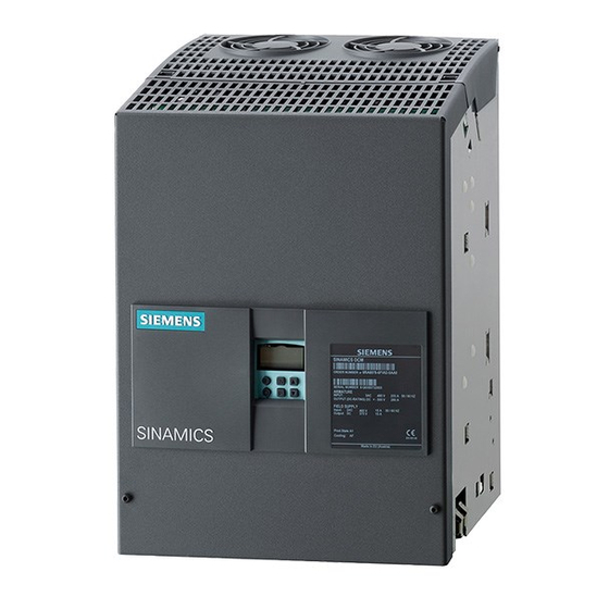
③ Order codes for options (according to ordering information for options) (order-specific) ④ Serial number bar code (order-specific) ⑤ Product version Rating plate on front cover Rating plate in the device SINAMICS DCM Control Module Operating Instructions, 12/2018, A5E34888669A... -
Page 28: Ordering Information For Options And Accessories
Figure 2-1 Packaging label Ordering information for options and accessories Ordering information for options with order codes Article number of SINAMICS DCM Control Module with Z designation and order codes (multiple order codes together) and/or plain text, if necessary Table 2- 1... -
Page 29: Ordering Information For Accessories
Fuse monitoring module 6RY1803-0CM02 Fuse monitoring distributor 6RY1803-0CM26 incl. 3 m ribbon cable to connect to the SINAMICS DCM Control Module; can be snapped onto mounting rails according to DIN EN 50022-35x7.5 SINAMICS DCM Control Module Operating Instructions, 12/2018, A5E34888669A... - Page 30 Drive Control Chart (DCC) for SINAMICS and SIMOTION 6AU1810-1JA20-1XA0 Please contact your local Siemens office. See Chapters "Line reactors (Page 112)" and "Fuses (Page 116)" or contact your local Siemens office Table 2- 4 Article numbers for the Advanced Operator Panel AOP30...
- Page 31 2.3 Ordering information for options and accessories Ordering information for cable sets The SINAMICS DCM Control Module is supplied with front and rear plates mounted one on top of the other. The correct ribbon cables for this mounting type are already in place.
- Page 32 XIMP5 or XIMP3, XIMP6 on PCB transformers "Firing pulse transformer module" (side sections) to firing pulse trans- former modules (single boards) with terminals X11, X12, X13, X14, X15, X16, X21, X22, X23, X24, X25, X26 SINAMICS DCM Control Module Operating Instructions, 12/2018, A5E34888669A...
- Page 33 Control Module" to XF1 on PCB "Field supply power unit" 1 x RJ45 patch cable X45 on PCB "Power interface for the shielded (L = 1 m) Control Module" to X45 on PCB "Voltage measurement" SINAMICS DCM Control Module Operating Instructions, 12/2018, A5E34888669A...
- Page 34 Ordering information 2.3 Ordering information for options and accessories SINAMICS DCM Control Module Operating Instructions, 12/2018, A5E34888669A...
- Page 35 SINAMICS DCM Control Module. This is a highly cost- effective solution for those interested in a modern DC drive with the entire range of functions associated with the fully digital units in the SINAMICS DCM range.
-
Page 36: Additional Components
– SMC10 (resolver evaluation for speed actual value sensing) – SMC30 (incremental encoder evaluation for actual speed value acquisition) An SMC10 or SMC30 and up to three TMx modules can be connected to each CUD. SINAMICS DCM Control Module Operating Instructions, 12/2018, A5E34888669A... -
Page 37: Extended Functions
Simple closed-loop control functions can be implemented with the technology controller, e.g.: – Liquid level control – Temperature control – Dancer roll position control – Pressure control – Flow control – Simple control without higher-level control – Tension control SINAMICS DCM Control Module Operating Instructions, 12/2018, A5E34888669A... - Page 38 Description SINAMICS DCM Control Module Operating Instructions, 12/2018, A5E34888669A...
-
Page 39: Technical Data
Tipping is not permitted. Climatic influences Air temperature of -40 °C to +70 °C is permitted Biological influences Hazardous chemical substances Mechanically hazardous materials Only applies when product is in its original packing SINAMICS DCM Control Module Operating Instructions, 12/2018, A5E34888669A... -
Page 40: Ambient Temperature
- Temperature coefficient of the tachometer generator with temperature compensation: 0.15‰ every 10 °C (for analog tachometer generator only) - Constant setpoint (14-bit resolution) The option of operating with an extended frequency range can be provided on request. SINAMICS DCM Control Module Operating Instructions, 12/2018, A5E34888669A... -
Page 41: Transport, Unpacking, Installation
If the general safety instructions and remaining risks are not observed, accidents can occur involving severe injuries or death. • Observe the general safety instructions. • When assessing the risk, take into account remaining risks. SINAMICS DCM Control Module Operating Instructions, 12/2018, A5E34888669A... -
Page 42: Dimension Drawings
Transport, unpacking, installation 5.2 Installation 5.2.1 Dimension drawings Device All dimensions in mm Tolerance for external dimensions is +2 mm Figure 5-1 Device components after assembly (on delivery) SINAMICS DCM Control Module Operating Instructions, 12/2018, A5E34888669A... - Page 43 Transport, unpacking, installation 5.2 Installation Figure 5-2 Device components arranged alongside each other SINAMICS DCM Control Module Operating Instructions, 12/2018, A5E34888669A...
- Page 44 Transport, unpacking, installation 5.2 Installation Firing pulse transformer module Dimensions of the complete module W × H = 260 × 298 mm Control PCB: Figure 5-3 Dimension drawing, control PCB SINAMICS DCM Control Module Operating Instructions, 12/2018, A5E34888669A...
-
Page 45: Dividing The Unit
② ③ Pull the front cover towards you and then upwards to remove it Unplug the cable connections between the two plates. ④ Loosen the screws Figure 5-4 Dividing the unit (1) SINAMICS DCM Control Module Operating Instructions, 12/2018, A5E34888669A... - Page 46 Transport, unpacking, installation 5.2 Installation ① ② Pull the plate towards you and remove it Figure 5-5 Dividing the unit (2) SINAMICS DCM Control Module Operating Instructions, 12/2018, A5E34888669A...
-
Page 47: Removal/Installation And Division Of Modules
To remove other modules, remove the shield by pulling it towards you. You will need to unscrew ④ ② the field terminal and then loosen the screws before doing this. Figure 5-6 Removing modules (1) SINAMICS DCM Control Module Operating Instructions, 12/2018, A5E34888669A... - Page 48 To remove the fuse monitoring equipment, pull the cables out from the module and loosen the ① screws To remove the voltage measurement equipment, pull the cables out from the module and loosen the ② screws Figure 5-7 Removing modules (2) SINAMICS DCM Control Module Operating Instructions, 12/2018, A5E34888669A...
- Page 49 Use the edge of a table to separate the two terminal parts ② Use the edge of a table to separate the small control boards Figure 5-8 Dividing the firing pulse transformer module SINAMICS DCM Control Module Operating Instructions, 12/2018, A5E34888669A...
- Page 50 Transport, unpacking, installation 5.2 Installation Installing terminal strips ① Leave the two crossbraces for supporting the side sections of the modules in the device. Figure 5-9 Firing pulse transformer module SINAMICS DCM Control Module Operating Instructions, 12/2018, A5E34888669A...
- Page 51 The two snap-on parts for the DIN rail, which satisfies DIN EN 50022-35x7.5, are mounted on the ② small control boards with M3x8 screws Figure 5-11 External mounting of the small firing pulse transformer boards SINAMICS DCM Control Module Operating Instructions, 12/2018, A5E34888669A...
- Page 52 External mounting of fuse monitoring equipment Mount the module on the spacing bolts. ① Ferrous fixing elements (x2) ② Insulating fixing elements (x5) Figure 5-12 External mounting of the fuse monitoring equipment SINAMICS DCM Control Module Operating Instructions, 12/2018, A5E34888669A...
- Page 53 External mounting of voltage measurement equipment Mount the module on the spacing bolts. ① Ferrous fixing elements (x2) ② Insulating fixing elements (x4) Figure 5-13 External mounting of the voltage measurement equipment SINAMICS DCM Control Module Operating Instructions, 12/2018, A5E34888669A...
-
Page 54: Installing Options And Accessories
Note the information provided on "Electrostatic sensitive devices (ESD)" in Chapter 1. Note Use the supplied mounting aid. See Chapter "Replacing the CUD (Page 656)". ① Unlock and tilt up the BOP support Figure 5-14 Installing a second CUD (1) SINAMICS DCM Control Module Operating Instructions, 12/2018, A5E34888669A... - Page 55 Secure the CUD using four screws (screw and washer assembly, M3×6), tightening torque 1 Nm Figure 5-15 Installing a second CUD (2) Lock the BOP support again. CAUTION: Do not clamp the BOP cable Figure 5-16 Installing a second CUD (3) SINAMICS DCM Control Module Operating Instructions, 12/2018, A5E34888669A...
- Page 56 Transport, unpacking, installation 5.2 Installation SINAMICS DCM Control Module Operating Instructions, 12/2018, A5E34888669A...
- Page 57 When required, additional covers should be provided in the control cabinet (for example, in the area around the busbars). To operate the SINAMICS DC MASTER, both front cover fixing screws must be tight. SINAMICS DCM Control Module Operating Instructions, 12/2018, A5E34888669A...
-
Page 58: Instructions For Emc-Compliant Drive Installation
Should you require further information or encounter specific problems which have not been dealt with in enough detail for your field of application, please contact your local Siemens office. 6.1.1... - Page 59 The term second environment refers to all locations outside residential areas. These are basically industrial areas which are powered from the medium-voltage network via their own transformers. Figure 6-1 Definition of the first and second environments SINAMICS DCM Control Module Operating Instructions, 12/2018, A5E34888669A...
- Page 60 If the drive forms part of a system, it does not initially need to fulfill any interference emission requirements, but the EMC Directive does require the system as a whole to be electromagnetically compatible with its environment. SINAMICS DCM Control Module Operating Instructions, 12/2018, A5E34888669A...
-
Page 61: Emc-Compliant Drive Installation (Installation Instructions)
For this reason, EMC rules do not need to be implemented to the letter in all cases, provided that measures are tested on a case-by- case basis. SINAMICS DCM Control Module Operating Instructions, 12/2018, A5E34888669A... - Page 62 (ground) at several points, and connected at several points outside the control cabinet. Foil shields should be avoided as they are are at least 5 times less effective than braided shields. SINAMICS DCM Control Module Operating Instructions, 12/2018, A5E34888669A...
- Page 63 Generally speaking, "ground" refers to all metallic conductive parts that can be connected to a protective conductor, such as the cabinet enclosure, motor enclosure or foundation ground. Cabinet configuration and shielding Figure 6-3 Shielding at control cabinet inlet SINAMICS DCM Control Module Operating Instructions, 12/2018, A5E34888669A...
- Page 64 Connecting 6.1 Instructions for EMC-compliant drive installation Figure 6-4 Shielding in control cabinet Connecting shields on the SINAMICS DC MASTER Figure 6-5 Connecting shields SINAMICS DCM Control Module Operating Instructions, 12/2018, A5E34888669A...
-
Page 65: Shield Connection
Notice! Risk of pinching cable if screws tightened too much ③ Ferrous tube or cable tie on bare ferrous comb-type/toothed bar ④ Clamp with ferrous backing plate on cable support rail Figure 6-7 Shield connection SINAMICS DCM Control Module Operating Instructions, 12/2018, A5E34888669A... -
Page 66: Arranging Components For Converter Units
An incorrect arrangement can destroy a thyristor (short-circuit) and rupture a fuse. • The components must be wired in the following order: Line supply – radio interference suppression filter – commutating reactor – power unit. SINAMICS DCM Control Module Operating Instructions, 12/2018, A5E34888669A... - Page 67 6RX1800 - 1GF04 Operating temperature 0 °C to 40 °C. Rated frequency 50/60 Hz (± 6%). Further information on the RFI suppression filters can be found on the Internet page of Epcos (Epcos (http://en.tdk.eu)). SINAMICS DCM Control Module Operating Instructions, 12/2018, A5E34888669A...
-
Page 68: Information On Line-Side Harmonics Produced By Converter Units In A Fully- Controlled Two-Pulse Bridge Circuit Configuration (B6C And (B6)A(B6)C)
Strom sechspulsiger netzgeführter Stromrichter (Harmonics in the Line-Side Current of Six-Pulse, Line-Commutated Converters)" by H. Arremann and G. Möltgen, Siemens Research and Development Division, Volume 7 (1978) No. 2, © Springer-Verlag 1978. In addition, the formulas are specified which, depending on the actual operating data in use... - Page 69 S and L that have been calculated in this way. If the actual values deviate from these, a separate calculation will have to be made. SINAMICS DCM Control Module Operating Instructions, 12/2018, A5E34888669A...
-
Page 70: Data On The Line-Side Harmonics From Converter Units In A Fully-Controlled Ac Bridge Circuit B2C
2.6% 2.7% 8.2% 8.7% 2.4% 2.6% 6.9% 7.4% 2.3% 6.0% 2.2% 2.3% 5.3% 5.6% 2.1% 2.2% 4.7% 5.0% 2.0% 4.3% 1.9% 2.0% 3.9% 4.2% 1.8% 2.0% 3.6% 3.8% Fundamental content converter circuit SINAMICS DCM Control Module Operating Instructions, 12/2018, A5E34888669A... -
Page 71: Cable Routing In The Unit
Cables, which are not mechanically fixed in the device, must be externally fixed. Figure 6-9 Example for cable routing when fully expanded Note The PROFINET cables must be routed into the device from the top (PROFINET is only available with Communication Board(s) CBE20). SINAMICS DCM Control Module Operating Instructions, 12/2018, A5E34888669A... - Page 72 XB, current transformer connection Route all cables into the device from the bottom. Cable clamps are provided at the side panels to mechanically fix the cables. Figure 6-10 Cable routing, power interface SINAMICS DCM Control Module Operating Instructions, 12/2018, A5E34888669A...
- Page 73 Note Routing the PROFIBUS connection If the PROFIBUS bus connector is connected and removed in a system during operation, the system manufacturer must ensure that the PROFIBUS connection is routed outwards. SINAMICS DCM Control Module Operating Instructions, 12/2018, A5E34888669A...
- Page 74 Strain relief of the cables through positioning on shield clamps on the lower edge of the housing. Figure 6-11 Routing the functional safety cable Note It is not required to use shielded cables and shield connection in the device. SINAMICS DCM Control Module Operating Instructions, 12/2018, A5E34888669A...
-
Page 75: Block Diagram With Connection Suggestion
Connecting 6.3 Block diagram with connection suggestion Block diagram with connection suggestion Figure 6-12 Open-loop/closed-loop control section block diagram SINAMICS DCM Control Module Operating Instructions, 12/2018, A5E34888669A... - Page 76 Connecting 6.3 Block diagram with connection suggestion Figure 6-13 Block diagram for power interface SINAMICS DCM Control Module Operating Instructions, 12/2018, A5E34888669A...
- Page 77 Connecting 6.3 Block diagram with connection suggestion Figure 6-14 Block diagram for fuse monitoring/voltage measurement equipment, firing pulse transformers, power unit SINAMICS DCM Control Module Operating Instructions, 12/2018, A5E34888669A...
-
Page 78: Connecting The External Power Unit
EN 61439-1. Please refer to the Chapter "Division options (Page 83)" for options on how to position the two plates and how the unit can be divided. SINAMICS DCM Control Module Operating Instructions, 12/2018, A5E34888669A... - Page 79 • Apply one of the following measures: – Use cables with double insulation. – Observe adequate clearances, e.g. through the use of spacers. – Route the cables in separate cable ducts or pipes. SINAMICS DCM Control Module Operating Instructions, 12/2018, A5E34888669A...
- Page 80 Connecting 6.4 Connecting the external power unit Figure 6-15 Connection of a 4-quadrant power unit (1) SINAMICS DCM Control Module Operating Instructions, 12/2018, A5E34888669A...
- Page 81 Connecting 6.4 Connecting the external power unit Figure 6-16 Connection of a 4-quadrant power unit (2) SINAMICS DCM Control Module Operating Instructions, 12/2018, A5E34888669A...
- Page 82 Connecting 6.4 Connecting the external power unit Figure 6-17 Connection of a 2-quadrant power unit (1) SINAMICS DCM Control Module Operating Instructions, 12/2018, A5E34888669A...
- Page 83 Connecting 6.4 Connecting the external power unit Figure 6-18 Connection of a 2-quadrant power unit (2) SINAMICS DCM Control Module Operating Instructions, 12/2018, A5E34888669A...
- Page 84 Electric shock in the event of voltage flashovers at the temperature sensor Voltage flashovers in the signal electronics can occur in motors without safe electrical separation of the temperature sensors. • Use temperature sensors that comply with the specifications relating to protective separation. SINAMICS DCM Control Module Operating Instructions, 12/2018, A5E34888669A...
-
Page 85: Division Options
Some examples are shown below: Note The SINAMICS DCM Control Module is supplied with front and rear plates mounted one on top of the other. The correct cables (connectors X21A, X22A, XS20, XS21, and X102) for this mounting type are already in place. - Page 86 Example 1: Rear plate and front plate mounted one on top of the other or at a distance from each other, firing pulse transformer module not divided Short-circuit proof cable installation Figure 6-20 Division options – Example 1 SINAMICS DCM Control Module Operating Instructions, 12/2018, A5E34888669A...
- Page 87 (for each fuse being monitored) Voltage sensing devices (XU1, XV1, Single wires (short-circuit proof See also Chapter XW1, XC1, XD1 etc.) routing), "Connecting the external U-V-W twisted, C-D twisted power unit (Page 76)" SINAMICS DCM Control Module Operating Instructions, 12/2018, A5E34888669A...
- Page 88 For mechanical modifications, see Chapter "Installation (Page 39)". Short-circuit proof cable installation Figure 6-21 Division options – Example 2 SINAMICS DCM Control Module Operating Instructions, 12/2018, A5E34888669A...
- Page 89 (for each fuse being monitored) Voltage sensing devices (XU1, XV1, Single wires (short-circuit proof See also Chapter XW1, XC1, XD1 etc.) routing), "Connecting the external U-V-W twisted, C-D twisted power unit (Page 76)" SINAMICS DCM Control Module Operating Instructions, 12/2018, A5E34888669A...
- Page 90 For mechanical modifications, see Chapter "Installation (Page 39)". Short-circuit proof cable installation Figure 6-22 Division options – Example 3 SINAMICS DCM Control Module Operating Instructions, 12/2018, A5E34888669A...
- Page 91 (for each fuse being monitored) Voltage sensing devices (XU1, XV1, Single wires (short-circuit proof See also Chapter XW1, XC1, XD1 etc.) routing), "Connecting the external U-V-W twisted, C-D twisted power unit (Page 76)" SINAMICS DCM Control Module Operating Instructions, 12/2018, A5E34888669A...
- Page 92 Connecting 6.5 Division options Example 4: Parallel connection of power units with a shared set of control electronics Short-circuit-proof routing Figure 6-23 Division options – Example 4 SINAMICS DCM Control Module Operating Instructions, 12/2018, A5E34888669A...
- Page 93 ● Please refer to the Chapter titled "Connecting fuse monitoring equipment (Page 110)" for information on fuse monitoring equipment. ● Please also note the information contained in Chapter "Parallel connection of power units (Page 111)". SINAMICS DCM Control Module Operating Instructions, 12/2018, A5E34888669A...
-
Page 94: Connecting Current Transformers
Connecting current transformers ① Current transformers ② Remove the connection between the current transformers and module A7 and connect the current transformer cables directly to the current transformers' screw terminals. Rear view SINAMICS DCM Control Module Operating Instructions, 12/2018, A5E34888669A... - Page 95 A3 (= AK3 = V), and A5 (= AK5 = W) (see circuit diagram below). <3> Do not connect X1, X2 <4> Measurement of armature voltage: connection of KW (AW) - C and AW (KW) - D Figure 6-24 Circuit (B6)A(B6)C (4-quadrant drive) SINAMICS DCM Control Module Operating Instructions, 12/2018, A5E34888669A...
- Page 96 (if SITOR sets 6QG12 are being used without a transformer module for measuring actual current values, there is no need for an A7 module) Figure 6-25 SITOR 4Q before modification SINAMICS DCM Control Module Operating Instructions, 12/2018, A5E34888669A...
- Page 97 Measurement of armature voltage: Connection of KW - C and AW - D (see the circuit diagram below for details of how to connect to Faston tabs on the thyristor blocks). Figure 6-26 Circuit B6C (2-quadrant drive) SINAMICS DCM Control Module Operating Instructions, 12/2018, A5E34888669A...
- Page 98 (if SITOR sets 6QG12 are being used without a transformer module for measuring actual current values, there is no need for an A7 module). Figure 6-27 SITOR 2Q before modification SINAMICS DCM Control Module Operating Instructions, 12/2018, A5E34888669A...
-
Page 99: Measurement Of The Armature Current
General information Measuring circuit on the power interface for the Control Module: Figure 6-28 Current measurement Arrangement on the power interface for the Control Module: Arrangement of X_I_IST Arrangement of terminals XB SINAMICS DCM Control Module Operating Instructions, 12/2018, A5E34888669A... - Page 100 On delivery, actual current value measurement on the SINAMICS DCM Control Module is configured in such a way as to ensure an actual current value signal of 1 V at the rated device current.
-
Page 101: Current Measurement With Two Current Transformers On The Line Side
Load voltage (= mean value over 1 current crest, not the rms value or mean value over the entire period); recommended value = 1 V ü = Transformation ratio of the current transformer (I2/I1) (in general, ü = 1/number of turns) Rated armature DC current SINAMICS DCM Control Module Operating Instructions, 12/2018, A5E34888669A... - Page 102 1: Measurement of armature actual current value via X177.1/2 2: Measurement of armature actual current value via X177.3/4 3: Measurement of armature actual current value via X177.5/6 4: Measurement of armature actual current value via X177.7/8 SINAMICS DCM Control Module Operating Instructions, 12/2018, A5E34888669A...
-
Page 103: Current Measurement Via Terminal Block Xb-1 To Xb-4 With External Measuring Circuit
The output signal of the V-circuit is connected to terminals XB-1 (+) and XB-2 (-). Terminals XB-3 and XB-4 are not used. S700 switch positions: 2 – 3 connected 5 – 6 connected 8 – 9 connected Remove R701! The difference amplifier is not used. SINAMICS DCM Control Module Operating Instructions, 12/2018, A5E34888669A... - Page 104 Input voltage at rated armature current/10 p51824 = Load The load resistor for the open-delta connection should be located externally, but must not be grounded externally. Terminal XB-2 is used for grounding. R701 should be removed. SINAMICS DCM Control Module Operating Instructions, 12/2018, A5E34888669A...
- Page 105 The load resistor of the LEM current transducer should be located externally and grounded with the power supply. Since shunt amplifiers generally have a ±10 V voltage output, they do not require a load. SINAMICS DCM Control Module Operating Instructions, 12/2018, A5E34888669A...
- Page 106 5 (bipolar) Load The load resistor should be located externally and grounded with the LEM transformer's power supply. The value should be dimensioned to produce a 1 V voltage at the rated current. SINAMICS DCM Control Module Operating Instructions, 12/2018, A5E34888669A...
-
Page 107: Offset Correction Via Xn1
6.6.4 External current measurement via X21A or X_I_IST For the arrangement of the terminals at the Power Interface of the SINAMICS DCM Control Module, see also the diagram in Chapter "General information (Page 97)". X21A-23 and X_I_IST-1 = I_IST, negative actual current value... -
Page 108: Information On The Differential Input, Control Limits, And Grounding
RATED be measured. It is vital for users of the SINAMICS DCM Control Module to realize that they need to check whether the method used for current measurement is really able to map the desired overcurrents and the expected peak values within the tolerance required. It is important to check the current measurement circuit to ensure that current mapping remains linear right through to the desired overcurrent capacity. -
Page 109: Connecting The Firing Pulse Transformers
X21A for operation with just one current direction. If the "Firing pulse transformer module" has been divided (broken up), each firing pulse transformer must be connected to the terminal strip via two twisted cables. SINAMICS DCM Control Module Operating Instructions, 12/2018, A5E34888669A... -
Page 110: Parallel Connection Of Firing Pulses
24 V (22 V to 30 V) via their own power supply. The supply lines for the external firing pulse amplifiers must be sufficiently interference-proof to prevent thyristors misfiring under the prevailing conditions. SINAMICS DCM Control Module Operating Instructions, 12/2018, A5E34888669A... -
Page 111: Connecting Voltage Measurement Equipment
The voltage level selected must be the same on the printed circuit board and in the firmware or the voltages measured will be highly inaccurate. Voltage measurement equipment does not generate any ground leakage current. SINAMICS DCM Control Module Operating Instructions, 12/2018, A5E34888669A... -
Page 112: Connecting Fuse Monitoring Equipment
Example 4 shows the use of the fuse monitoring distributor for connecting two fuse monitoring units to a power interface. Ordering modules When delivered, the SINAMICS DCM Control Module contains a fuse monitoring unit. Additional fuse monitoring units as well as the fuse monitoring distributor module are available as accessories. -
Page 113: Parallel Connection Of Power Units
(mainly 1V1). Where only one set of SINAMICS DCM control electronics is being used, with firing pulses connected in parallel accordingly, it is not easy to determine how the current is split between the power units. -
Page 114: Field Supply
Line reactors should be dimensioned to produce a short-circuit voltage of between 4% and 10% (based on the rated field current and taking supply impedance into account). Local regulations regarding line harmonic distortion need to be observed when selecting line reactors. SINAMICS DCM Control Module Operating Instructions, 12/2018, A5E34888669A... - Page 115 0.019 mH 464.7 W 819.9 W 75 kA (200 ms) 164.2 kg 1000 V 6RX1800-4FK18 2324 A AC 0.015 mH 671.8 W 1056.7 W 75 kA (200 ms) 258.2 kg 1000 V SINAMICS DCM Control Module Operating Instructions, 12/2018, A5E34888669A...
- Page 116 0.031 mH 596.0 W 1011.8 W 75 kA (200 ms) 257.2 kg 1000 V 6RX1800-4KK07 2158 A AC 0.024 mH 484.8 W 1185.6 W 75 kA (200 ms) 360.2 kg 1000 V SINAMICS DCM Control Module Operating Instructions, 12/2018, A5E34888669A...
- Page 117 ● The line reactors are suitable for 50 Hz and 60 Hz operation. In 60 Hz operation, the next highest voltage class should be selected e. g. 480 V at 50 Hz, 575 V at 60 Hz. Standards, approvals REACH, ROHS, CE, cULus SINAMICS DCM Control Module Operating Instructions, 12/2018, A5E34888669A...
- Page 118 T6.3 A/250 V F400 6RY1702-0BA00 T1 A / 250 V The slot for the fuses can be seen on Figure 6-34 Terminal/connector arrangement on the"Power interface for the Control Module" (Page 121). SINAMICS DCM Control Module Operating Instructions, 12/2018, A5E34888669A...
-
Page 119: Arrangement Of Printed Circuit Boards
Control Unit (CUD) (Advanced CUD and CUD on the right are options) ② Power interface for the Control Module ③ Firing pulse transformer module ④ Power unit field supply ⑤ Fuse monitoring ⑥ Voltage measurement Figure 6-30 Arrangement of printed circuit boards SINAMICS DCM Control Module Operating Instructions, 12/2018, A5E34888669A... -
Page 120: Arrangement Of Customer Connections (Connector Terminals, Faston Mounting Tabs)
6.15 Arrangement of customer connections (connector terminals, Faston mounting tabs) 6.15 Arrangement of customer connections (connector terminals, Faston mounting tabs) Control Unit (CUD) module Figure 6-31 Terminal/connector arrangement on the "Control Unit (CUD)" SINAMICS DCM Control Module Operating Instructions, 12/2018, A5E34888669A... - Page 121 The jumper STO to P24 must be removed for use of the safety function and the wiring performed according to one of the applications in Chapter "Functional safety (Page 665)" with a safety relay. SINAMICS DCM Control Module Operating Instructions, 12/2018, A5E34888669A...
- Page 122 Connecting 6.15 Arrangement of customer connections (connector terminals, Faston mounting tabs) Control Unit (CUD) module, option G63 Figure 6-33 Terminal/connector arrangement on the "Control Unit (CUD)" – Option G63 SINAMICS DCM Control Module Operating Instructions, 12/2018, A5E34888669A...
- Page 123 Connecting 6.15 Arrangement of customer connections (connector terminals, Faston mounting tabs) "Power interface for the Control Module" module Figure 6-34 Terminal/connector arrangement on the "Power interface for the Control Module" SINAMICS DCM Control Module Operating Instructions, 12/2018, A5E34888669A...
-
Page 124: "Voltage Measurement" Module
Modules for option G63 Figure 6-35 Terminal/connector arrangement on the "Cabinet Board" Figure 6-36 Terminal arrangement on the "Terminal Module Cabinet (TMC)" "Voltage measurement" module Figure 6-37 Terminal/connector arrangement on the "Voltage measurement" SINAMICS DCM Control Module Operating Instructions, 12/2018, A5E34888669A... - Page 125 Connecting 6.15 Arrangement of customer connections (connector terminals, Faston mounting tabs) "Fuse monitoring" module Figure 6-38 Terminal/connector arrangement on the "Fuse monitoring" SINAMICS DCM Control Module Operating Instructions, 12/2018, A5E34888669A...
- Page 126 • The terminals with the same names on terminal strips XIMP_4, XIMP_5, and XIMP_6. • X21A and X21PAR, X22A and X22PAR • Figure 6-39 Terminal/connector arrangement on the "Firing pulse transformer module" SINAMICS DCM Control Module Operating Instructions, 12/2018, A5E34888669A...
- Page 127 6.15 Arrangement of customer connections (connector terminals, Faston mounting tabs) "Connector Board" module Figure 6-40 Terminal/connector arrangement on the "Connector Board" "Fuse monitoring distributor" module Figure 6-41 Connector arrangement on the "Fuse monitoring distributor" SINAMICS DCM Control Module Operating Instructions, 12/2018, A5E34888669A...
-
Page 128: Connector Assignment (Terminals, Faston Mounting Tabs, Ribbon Cables)
Dimensioning the connection cables The information regarding terminal connection options in the tables below is based on values from the terminal data sheets. The connecting cables must be dimensioned for the prevailing currents. SINAMICS DCM Control Module Operating Instructions, 12/2018, A5E34888669A... -
Page 129: Connecting The Protective Conductor
Functional safety 6.16.1 Connecting the protective conductor The SINAMICS DCM Control Module has connecting lugs at the side of both cradles to connect the protective conductor. In the delivery condition (both cradles assembled), the protective conductor should be connected to one of these lugs. Minimum cross section 4 mm If the two cradles are installed separately, then a protective conductor must be connected to both cradles. - Page 130 Recommended conductor cross-section 1.5 mm Internal protection with F200 fuses (6.3 A, time-lag. See Chapter "Fuses (Page 116)"), external protection 6 A ... 16 A, B or C characteristic "Power interface for the Control Module" module SINAMICS DCM Control Module Operating Instructions, 12/2018, A5E34888669A...
-
Page 131: Open-Loop And Closed-Loop Control Section
Modular jack 8/4 (RJ45) XB-1... XB-8, X_I_IST, XM: Type Wago 256 spring-loaded terminal Connection capacity 0.08-2.5 mm , AWG 18-12 Stripped length 5-6 mm XT5, XT6: Type Faston connecting tabs, 2.8 × 0.8 mm SINAMICS DCM Control Module Operating Instructions, 12/2018, A5E34888669A... - Page 132 DO (CUD left X177:15-22 + CUD right DO 3 Digital output 3 X177:15-22): 800 mA internal protection circuit (freewheeling diode) 23, 24 Ground, digital If overload occurs: alarm A60018 SINAMICS DCM Control Module Operating Instructions, 12/2018, A5E34888669A...
- Page 133 Resolution approx. 0.66 mV (±14 bits) Common-mode controllability: ±15 V Note: An external armature voltage actual value can also be connected at this input. See function diagram 6902 in the SINAMICS DCM List Manual. Reference voltage Reference voltage ±10 V Tolerance ±1% at 25 °C...
- Page 134 X177 Connections for temperature sensor (motor interface 1) Temp 1 Sensor acc. to p50490 (refer to SINAMICS DCM List Manual) The cable to the temperature sensor on the motor must be shielded. Temp 2 (sense cable) The shield is to be connected to ground at both ends.
- Page 135 Differential voltage ≤ 27 V ≤ 22 V ≤ 18 V ≤ 16 V ≤ 14 V Differential voltage of encoder pulses without load (= approximately the supply voltage of the incremental encoder) SINAMICS DCM Control Module Operating Instructions, 12/2018, A5E34888669A...
- Page 136 The shield should be connected to the SINAMICS DC MASTER shield support over a large area. Note For connecting an incremental encoder see also Chapter "Applications (Page 661)". SINAMICS DCM Control Module Operating Instructions, 12/2018, A5E34888669A...
- Page 137 Current transformer T2 - k2 Amplifier output from T3 Configuration of current transformers in accordance with p51824 M_BUERDE Current transformer T3 - l3 M_BUERDE Current transformer T3 - k3 "Power interface for the Control Module" module SINAMICS DCM Control Module Operating Instructions, 12/2018, A5E34888669A...
- Page 138 Receive cable, RS232 standard (V.24) "Control Unit (CUD)" module Note Only one of the two interfaces – RS485 (X178-3, 4) or RS232 (X179-3, 4) – may be used. Figure 6-43 Arrangement X178 and X179 SINAMICS DCM Control Module Operating Instructions, 12/2018, A5E34888669A...
- Page 139 Transmit data - Receive data + Reserved, do not use Reserved, do not use Receive data - Reserved, do not use Reserved, do not use Shield Permanently connected to ground "Advanced CUD" module SINAMICS DCM Control Module Operating Instructions, 12/2018, A5E34888669A...
-
Page 140: Parallel Interface
See X177.25 and 26 setpoint 27, 28 AI 1 +, AI 1 - Analog input 1 See X177.27 and 28 29, 30 AI 2 +, AI 2 - Analog input 2 See X177.29 and 30 SINAMICS DCM Control Module Operating Instructions, 12/2018, A5E34888669A... - Page 141 Receive cable +, - See X177.39 and 40 "Cabinet Board" module Note: The terminals on X177_5 are connected in parallel to the terminals with the same name on the Terminal Module Cabinet (TMC). SINAMICS DCM Control Module Operating Instructions, 12/2018, A5E34888669A...
-
Page 142: Memory Card Slot
Soldering lugs for load resistor R708 (X707, X708) X707 Connection to XB-7 X708 Connection to XB-8 "Power interface for the Control Module" module Memory card slot Figure 6-44 "Control Unit (CUD)" module, memory card slot SINAMICS DCM Control Module Operating Instructions, 12/2018, A5E34888669A... - Page 143 ● Modbus TCP function: The Modbus TCP function requires that the memory card is always inserted. ● Saving the Diagstor.spd diagnostics file to the \USER\SINAMICS\DATA\LOG directory. See also Chapter "Trend recorder function (Page 595)" SINAMICS DCM Control Module Operating Instructions, 12/2018, A5E34888669A...
-
Page 144: Voltage Measurement Equipment
Rated line voltage (armature) ≤5.6 V Phases U-V-W (p51821 = 6) (5.6 V) Measurement of the armature Rated line voltage (armature) ≤5.6 V voltage (p51821 = 6) (5.6 V) "Voltage measurement" module SINAMICS DCM Control Module Operating Instructions, 12/2018, A5E34888669A... -
Page 145: Fuse Monitoring Equipment
Resistance between two associated connections: 100.4 kΩ **) XS3_3 Fuse 2 XS4_3 (250 V) XS5_3 Fuse 3 XS6_3 (250 V) XS7_3 Fuse 4 XS8_3 (250 V) XS9_3 Fuse 5 XS10_3 (250 V) XS11_3 Fuse 6 XS12_3 (250 V) SINAMICS DCM Control Module Operating Instructions, 12/2018, A5E34888669A... -
Page 146: Firing Pulse Transformers
5 - 6 mm X12_1, X14_1, X15_1, X16_1, X25_1 Type Faston mounting tabs, 6.3 mm The P24 on the "Power interface for the Control Module" is protected by F400 fuses (1 A, time-lag). SINAMICS DCM Control Module Operating Instructions, 12/2018, A5E34888669A... - Page 147 Only to be connected if the firing pulse transformer module is divided up (see terminal strip XIMP_1) G, K Firing cable, thyristor V11 Firing pulse (see below) gate (G) to auxiliary cathode (K) SINAMICS DCM Control Module Operating Instructions, 12/2018, A5E34888669A...
- Page 148 Only to be connected if the firing pulse transformer module is divided up (see terminal strip XIMP_4) G, K Firing cable, thyristor V23 Firing pulse (see below) gate (G) to auxiliary cathode (K) SINAMICS DCM Control Module Operating Instructions, 12/2018, A5E34888669A...
- Page 149 X25_1 Armature voltage 1D1 See also Chapter "Connecting the external power unit". "Firing pulse transformer module" SINAMICS DCM Control Module Operating Instructions, 12/2018, A5E34888669A...
-
Page 150: Firing Pulse
The pulse shape of the current depends on the length of the cable to the thyristor (cathode/gate). Cable inductance causes the rising edge of the current pulse to become slower as the cable length increases. SINAMICS DCM Control Module Operating Instructions, 12/2018, A5E34888669A... - Page 151 Substitution load 20 Ω in parallel with 2 diodes Substitution load 20 Ω in parallel with 4 diodes ① Control signal ② Voltage at load (0.5 V/div) ③ Current through load (0.5 A/div) Figure 6-46 Firing pulse – Oscillograms SINAMICS DCM Control Module Operating Instructions, 12/2018, A5E34888669A...
-
Page 152: Ribbon Cables
Power interface for the Control Module / firing pulse transformer module Connectors X21A and X21PAR are connected in parallel on the firing pulse transformer module, except for I_IST (pin 23) and M_I_IST (pin 24) SINAMICS DCM Control Module Operating Instructions, 12/2018, A5E34888669A... - Page 153 Electronic ground Free Free Electronic ground Free Power interface for the Control Module / firing pulse transformer module Connectors X22A and X22PAR are connected in parallel on the firing pulse transformer module SINAMICS DCM Control Module Operating Instructions, 12/2018, A5E34888669A...
- Page 154 Fuse monitoring SICHERUNG_OK 24 V logic Fuse monitoring SICHERUNG_OK 24 V logic Fuse monitoring SICHERUNG_OK 24 V logic Ground Ground Power interface for the Control Module / fuse monitoring or fuse monitoring distributor SINAMICS DCM Control Module Operating Instructions, 12/2018, A5E34888669A...
- Page 155 24 V logic Fuse monitoring SICHERUNG_OK 24 V logic Fuse monitoring SICHERUNG_OK 24 V logic Fuse monitoring SICHERUNG_OK 24 V logic Ground Ground Power interface for the Control Module / fuse monitoring distributor SINAMICS DCM Control Module Operating Instructions, 12/2018, A5E34888669A...
- Page 156 22...26 V +24 V firing supply P24_ZV 22...26 V Electronic ground Heat sink temperature sensor KK_TEMP_FELD Analog Electronic ground Electronic ground Power interface for the Control Module / field supply power unit SINAMICS DCM Control Module Operating Instructions, 12/2018, A5E34888669A...
- Page 157 A 24 V power supply is required to operate the AOP30. For a maximum cable length of 50 m, this can be taken from the CUD of the SINAMICS DCM. An external power supply must be used for cable lengths > 50 m.
- Page 158 Rated voltage 24 V, maximum current load 200 mA, leakage current maximum 0.5 mA. Connection to diagnostic circuit of the safety relay (PELV circuit). "Allocation Board" module Note The maximum cable length that can be connected is 30 m. SINAMICS DCM Control Module Operating Instructions, 12/2018, A5E34888669A...
-
Page 159: Additional System Components
Note The modules SMC10, SMC30, TM15, TM31 and TM150 must not be connected with the DRIVE-CLiQ hubs DME20 and DMC20 during operation with SINAMICS DCM. DRIVE-CLiQ interface On the SINAMICS DC MASTER, up to three terminal modules TM15/TM31/TM150 can be connected to the DRIVE-CLiQ in any desired combination and in addition one Sensor Module Cabinet-Mounted SMC10 or SMC30 can be connected. -
Page 160: Safety Instructions
• Only withdraw or insert the Option Board when the Control Unit is de-energized. NOTICE Qualified personnel The CBE20 must only be operated by qualified personnel. The ESD information must be observed. SINAMICS DCM Control Module Operating Instructions, 12/2018, A5E34888669A... -
Page 161: Interface Description
7.1 Option Board: CBE20 Communication Board Ethernet 7.1.3 Interface description 7.1.3.1 Overview Figure 7-1 Interface description CBE20 MAC address The MAC address of the Ethernet interface is located on the upper side of the board. SINAMICS DCM Control Module Operating Instructions, 12/2018, A5E34888669A... - Page 162 For diagnostic purposes, the ports have one green and one yellow LED. Cable and connector types Information on PROFINET cables and connectors can be found in the following catalog: Industrial Communication Catalog IK PI, 2009 Edition, SINAMICS DCM Control Module Operating Instructions, 12/2018, A5E34888669A...
-
Page 163: Meaning Of The Leds
Green Flashing light Control Unit task system has synchronized with the IRT clock and data is being exchanged. Continuous Task system and MC-PLL have synchronized with the IRT clock. light SINAMICS DCM Control Module Operating Instructions, 12/2018, A5E34888669A... - Page 164 CBE20. board, if required, Possible causes: replace. The CBE20 was withdrawn after booting. • The CBE20 is defective. • Orange 0.5 Hz Firmware of the CBE20 currently being updated. – flashing light SINAMICS DCM Control Module Operating Instructions, 12/2018, A5E34888669A...
-
Page 165: Installation
Tightening torque: 1 Nm Installing the CBE20 7.1.6 Technical data Table 7- 5 Technical data Communication Board CBE20 Unit Value 6SL3055-0AA00-2EBx Max. current requirements (at 24 V DC) Power loss Weight < 0.1 SINAMICS DCM Control Module Operating Instructions, 12/2018, A5E34888669A... - Page 166 DRIVE-CLiQ to the Control Unit. The SMC10 is used to evaluate sensor signals from resolvers. 7.2.2 Interface description 7.2.2.1 Overview Figure 7-2 Interface overview for the SMC10 SINAMICS DCM Control Module Operating Instructions, 12/2018, A5E34888669A...
-
Page 167: X500 Drive-Cliq Interface
The maximum cable length that can be connected is 30 m. Note The two "+" or "M" terminals are jumpered in the connector. This ensures that the supply voltage is looped through. SINAMICS DCM Control Module Operating Instructions, 12/2018, A5E34888669A... -
Page 168: X520 Encoder System Interface
Reserved, do not use Reserved, do not use Reserved, do not use Reserved, do not use Ground Ground (for internal shield) Connector type: 25-pin SUB D connector Measuring current via temperature sensor connection: 2 mA SINAMICS DCM Control Module Operating Instructions, 12/2018, A5E34888669A... -
Page 169: Connection Example
Note: Both options depend on the LED status when component recognition is activated. Red/ orange Parameters for activating the identification of components via LED are 1.p9210 and 1.p9211 (see DCM List Manual) SINAMICS DCM Control Module Operating Instructions, 12/2018, A5E34888669A... -
Page 170: Dimension Drawing
Cause and rectification of faults Cause and rectification of faults Additional information about the cause and how to resolve faults can be found here: ● SINAMICS DCM List Manual ● Chapter "Commissioning with the Starter commissioning tool" 7.2.5 Dimension drawing... - Page 171 1. First shift the mounting slide downwards at the lug to release the interlocking with the mounting rail. 2. Swivel the component to the front and withdraw it upwards from the DIN rail. ① Mounting slide ② Mounting rail Figure 7-5 Removing from a DIN mounting rail SINAMICS DCM Control Module Operating Instructions, 12/2018, A5E34888669A...
- Page 172 7500 rpm The ratio between the ohmic resistance R and the inductance L (the primary winding of the resolver) determines whether the resolver can be evaluated with the SMC10. See the figure below: SINAMICS DCM Control Module Operating Instructions, 12/2018, A5E34888669A...
- Page 173 To check as shown in the previous figure, the impedances Z or Z (impedance between R1 and R2 with short-circuited or open outputs) from the encoder manufacturer's data sheet must be used. SINAMICS DCM Control Module Operating Instructions, 12/2018, A5E34888669A...
-
Page 174: Sensor Module Cabinet-Mounted Smc30
The SMC30 is used to evaluate encoder signals from encoders with TTL, HTL, or SSI interfaces. A combination of a TTL/HTL signal and SSI absolute signal is possible at terminals X521/X531 if both signals are derived from the same measured variable. SINAMICS DCM Control Module Operating Instructions, 12/2018, A5E34888669A... -
Page 175: Safety Instructions
When disconnecting plug-in connections during operation, arcs can result in severe injury or death. • Only disconnect or connect the encoder cables to Siemens motors in a voltage-free state if hot-plugging has not been specifically released. When using direct measuring systems (third-party encoders), ask the manufacturer whether hot-plugging is permitted. - Page 176 Damage through the use of incorrect DRIVE-CLiQ cables Damage or malfunctions can occur on the devices or system when incorrect or unreleased DRIVE-CLiQ cables are used. • Only use suitable DRIVE-CLiQ cables that have been released by Siemens for the respective application. Note Malfunctions due to polluted DRIVE-CLiQ interfaces Malfunctions can occur in the system through the use of polluted DRIVE-CLiQ interfaces.
- Page 177 Additional system components 7.3 Sensor Module Cabinet-Mounted SMC30 7.3.3 Interface description 7.3.3.1 Overview Figure 7-7 SMC30 interface description SINAMICS DCM Control Module Operating Instructions, 12/2018, A5E34888669A...
-
Page 178: X524 Electronic Power Supply
The maximum cable length that can be connected is 30 m. Note The two "+" or "M" terminals are jumpered in the connector. This ensures that the supply voltage is looped through. SINAMICS DCM Control Module Operating Instructions, 12/2018, A5E34888669A... - Page 179 Destruction of the encoder due to an incorrect supply voltage The encoder supply voltage can be assigned as 5 V or 24 V. The encoder may be destroyed if you enter the wrong parameters. • Select the appropriate motor supply voltage. SINAMICS DCM Control Module Operating Instructions, 12/2018, A5E34888669A...
- Page 180 Electric shock due to unconnected cable shields Hazardous touch voltages can occur through capacitive cross-coupling due to unconnected cable shields. • Attach the cable shield to the component via terminals for the encoder system connection. SINAMICS DCM Control Module Operating Instructions, 12/2018, A5E34888669A...
- Page 181 • Only use temperature sensors that satisfy the specifications for electrical separation according to IEC 61800-5-1. Note The maximum length of the temperature sensor cable is 100 m. The cables must be shielded. SINAMICS DCM Control Module Operating Instructions, 12/2018, A5E34888669A...
-
Page 182: Connection Examples
Connection example 2: HTL encoder, unipolar, with reference signal Because the physical transmission properties are more robust, the bipolar connection should always be used. The unipolar connection should only be used if the encoder type does not output push-pull signals. SINAMICS DCM Control Module Operating Instructions, 12/2018, A5E34888669A... - Page 183 Additional system components 7.3 Sensor Module Cabinet-Mounted SMC30 Figure 7-10 Connection example 2 Note Diagram of the wire jumpers for connecting unipolar HTL encoders with reference signal. SINAMICS DCM Control Module Operating Instructions, 12/2018, A5E34888669A...
- Page 184 Make sure that the connected encoder can be operated with a 24 V power supply. If an encoder that is designed for a 5 V supply is operated with a 24 V supply, this can destroy the encoder electronics. SINAMICS DCM Control Module Operating Instructions, 12/2018, A5E34888669A...
-
Page 185: Dimension Drawing
2. Swivel the component onto the DIN rail until you hear the mounting slide at the rear latch into position. 3. Slide the components along the mounting rail to either the left or right up to their final position. SINAMICS DCM Control Module Operating Instructions, 12/2018, A5E34888669A... - Page 186 1. First shift the mounting slide downwards at the lug to release the interlocking with the mounting rail. 2. Swivel the component to the front and withdraw it upwards from the DIN rail. ① Mounting slide ② Mounting rail Figure 7-12 Removing from a DIN mounting rail SINAMICS DCM Control Module Operating Instructions, 12/2018, A5E34888669A...
-
Page 187: Protective Conductor Connection And Shield Support
If the correct shielding procedures and the permissible cable lengths are not observed, the machine can be damaged or may malfunction. • Only use shielded cables. • Do not exceed the cable lengths stated in the technical data. SINAMICS DCM Control Module Operating Instructions, 12/2018, A5E34888669A... -
Page 188: Technical Data
(HTL bipolar) Low signal level Ldiff (HTL bipolar) High signal level Hdiff (SSI bipolar at X520 or X521/X531) Low signal level Ldiff (SSI bipolar at X520 or X521/X531) Signal frequency Edge clearance SINAMICS DCM Control Module Operating Instructions, 12/2018, A5E34888669A... - Page 189 For TTL encoders at X520 → Remote Sense → 100 m Because the physical transmission properties are more robust, the bipolar connection should always be used. The unipolar connection should only be used if the encoder type does not output push-pull signals. SINAMICS DCM Control Module Operating Instructions, 12/2018, A5E34888669A...
- Page 190 For encoders with a 5 V supply at X521/X531, the cable length depends on the encoder current (for 0.5 mm cable cross-sections): Figure 7-15 Max. cable length as a function of the encoder current drawn SINAMICS DCM Control Module Operating Instructions, 12/2018, A5E34888669A...
- Page 191 (reason: The voltage drop depends on the cable length and the encoder current). Figure 7-16 Signal characteristic of track A and track B between two edges: Time between two edges with incremental encoders Figure 7-17 Position of the zero pulse to the track signals SINAMICS DCM Control Module Operating Instructions, 12/2018, A5E34888669A...
-
Page 192: Terminal Module Tm15
Damage through the use of incorrect DRIVE-CLiQ cables Damage or malfunctions can occur on the devices or system when incorrect or unreleased DRIVE-CLiQ cables are used. • Only use suitable DRIVE-CLiQ cables that have been released by Siemens for the respective application. SINAMICS DCM Control Module... -
Page 193: Interface Description
Malfunctions can occur in the system through the use of polluted DRIVE-CLiQ interfaces. • Cover unused DRIVE-CLiQ interfaces with the supplied blanking covers. 7.4.3 Interface description 7.4.3.1 Overview Figure 7-18 TM15 interface overview SINAMICS DCM Control Module Operating Instructions, 12/2018, A5E34888669A... -
Page 194: Terminal Type
Reserved, do not use + (24 V) Power supply M (0 V) Electronics ground Blanking plate for DRIVE-CLiQ interfaces included in the scope of delivery; blanking plate (50 pieces) Article number: 6SL3066-4CA00-0AA0 SINAMICS DCM Control Module Operating Instructions, 12/2018, A5E34888669A... - Page 195 M1: A ground reference for DI/DO 0 to 7 (first potential group) must always be connected if at least one DI/DO of the potential group is used as either an input or output. DI/DO: Bidirectional digital input/output SINAMICS DCM Control Module Operating Instructions, 12/2018, A5E34888669A...
- Page 196 M3: A ground reference for DI/DO 16 to 23 (third potential group) must always be connected if at least one DI/DO of the potential group is used as either input or output. DI/DO: Bidirectional digital input/output SINAMICS DCM Control Module Operating Instructions, 12/2018, A5E34888669A...
-
Page 197: Connection Example
Additional system components 7.4 Terminal Module TM15 7.4.4 Connection example Figure 7-19 Example connection of TM15 SINAMICS DCM Control Module Operating Instructions, 12/2018, A5E34888669A... - Page 198 Red/ orange See SINAMICS DCM Parameter Manual for the parameters to activate the recognition of components via LED Cause and rectification of faults The following documents contain information about the cause of faults and how they can be...
-
Page 199: Dimension Drawing
2. Swivel the component onto the DIN rail until you hear the mounting slide at the rear latch into position. 3. Slide the components along the mounting rail to either the left or right up to their final position. SINAMICS DCM Control Module Operating Instructions, 12/2018, A5E34888669A... - Page 200 1. First shift the mounting slide downwards at the lug to release the interlocking with the mounting rail. 2. Swivel the component to the front and withdraw it upwards from the DIN rail. ① Mounting slide ② Standard mounting rail Figure 7-21 Removing from a mounting rail SINAMICS DCM Control Module Operating Instructions, 12/2018, A5E34888669A...
-
Page 201: Protective Conductor Connection And Shield Support
X524). If the ground terminal is actually grounded, then the enclosure is also grounded. An additional ground connection using the M4 screw is especially necessary if high potential bonding currents can flow (e.g. through the cable shield). SINAMICS DCM Control Module Operating Instructions, 12/2018, A5E34888669A... -
Page 202: Connector Coding
● 3 connectors on one component are encoded differently (i.e. X520, X521 and X522). ● Different component types are encoded differently. ● Otherwise identical components are encoded differently on the same machine, (e.g. several TM15-type components). SINAMICS DCM Control Module Operating Instructions, 12/2018, A5E34888669A... -
Page 203: Technical Data
(100% amplitude, 50%/50% duty cycle; with 0.5 A and a resistive load) Voltage drop in ON state 0.75 (max.) for maximum load in all circuits Leakage current in OFF state μA Max. 10 per channel SINAMICS DCM Control Module Operating Instructions, 12/2018, A5E34888669A... - Page 204 • (approx. 1 DRIVE-CLiQ clock cycle). Evaluation on the Control Unit (see function diagram) • For additional information: SINAMICS DCM List Manual, Chapter "Function block diagrams" Weight Protective conductor connection On enclosure with M4/1.8 Nm screw Approvals UL and cULus, http://www.ul.com (www.ul.com) File: E164110, Vol.
-
Page 205: Terminal Module Tm31
Supported types The SINAMICS DC MASTER only supports one version of the Terminal Module TM31: Table 7- 31 TM31 types TM31 article number Use with SINAMICS DC MASTER 6SL3055-0AA00-3AA0 Not possible 6SL3055-0AA00-3AA1 Possible SINAMICS DCM Control Module Operating Instructions, 12/2018, A5E34888669A... -
Page 206: Safety Instructions
Damage through the use of incorrect DRIVE-CLiQ cables Damage or malfunctions can occur on the devices or system when incorrect or unreleased DRIVE-CLiQ cables are used. • Only use suitable DRIVE-CLiQ cables that have been released by Siemens for the respective application. Note Malfunctions due to polluted DRIVE-CLiQ interfaces Malfunctions can occur in the system through the use of polluted DRIVE-CLiQ interfaces. -
Page 207: Interface Description
Additional system components 7.5 Terminal Module TM31 7.5.3 Interface description 7.5.3.1 Overview Figure 7-24 Interface description TM31 SINAMICS DCM Control Module Operating Instructions, 12/2018, A5E34888669A... -
Page 208: Terminal Type
Reserved, do not use + (24 V) Power supply M (0 V) Electronics ground The blanking covers for the DRIVE-CLiQ interfaces are included in the scope of delivery. Blanking covers (50 x) Article number: 6SL3066-4CA00-0AA0 SINAMICS DCM Control Module Operating Instructions, 12/2018, A5E34888669A... - Page 209 The two "+" or "M" terminals are jumpered in the connector. This ensures that the supply voltage is looped through. The current consumption increases by the value for the DRIVE-CLiQ node and digital outputs. SINAMICS DCM Control Module Operating Instructions, 12/2018, A5E34888669A...
- Page 210 This is achieved through one of the following measures: 1. Provide the ground reference of the digital inputs 2. A jumper to terminal M Note:: This removes isolation for these digital inputs. SINAMICS DCM Control Module Operating Instructions, 12/2018, A5E34888669A...
-
Page 211: X521 Analog Inputs
• The back EMF at the auxiliary voltage connections may only be in the range between -15 V and +15 V. Note The power supply for the analog inputs can be taken internally or from an external power supply unit SINAMICS DCM Control Module Operating Instructions, 12/2018, A5E34888669A... -
Page 212: Analog Inputs Current/Voltage Switch
If a KTY temperature sensor is connected with incorrect polarity, it is not possible to detect when the motor overheats. Overheating can cause damage to the motor. • Connect a KTY temperature sensor with the correct polarity. SINAMICS DCM Control Module Operating Instructions, 12/2018, A5E34888669A... - Page 213 This power supply is only used for powering the digital inputs. Note If the 24 V supply is briefly interrupted, the auxiliary voltage for the digital inputs is deactivated for this time. SINAMICS DCM Control Module Operating Instructions, 12/2018, A5E34888669A...
-
Page 214: X541 Bidirectional Digital Inputs/Outputs
Max. total load current of +24 V auxiliary voltage for terminals X540 and X541 combined: 150 mA DI/DO: Bidirectional digital input/output; M: Electronics ground Note An open input is interpreted as "low". SINAMICS DCM Control Module Operating Instructions, 12/2018, A5E34888669A... -
Page 215: X542 Relay Outputs
Overvoltage category: Class II acc. to EN 61800-5-1 DO: Digital output; NO: Normally open contact; NC: Normally closed contact; COM: Mid- position contact Depending on the parameterization and the supply voltage (P24) of the TM31 SINAMICS DCM Control Module Operating Instructions, 12/2018, A5E34888669A... - Page 216 Additional system components 7.5 Terminal Module TM31 7.5.4 Connection example Figure 7-25 TM31 connection example SINAMICS DCM Control Module Operating Instructions, 12/2018, A5E34888669A...
-
Page 217: Meanings Of The Leds On The Terminal Module Tm31
Red/ orange See SINAMICS DCM Parameter Manual for the parameters to activate the recognition of components via LED Cause and rectification of faults The following documents contain information about the cause of faults and how they can be... -
Page 218: Dimension Drawing
Additional system components 7.5 Terminal Module TM31 7.5.6 Dimension drawing Figure 7-26 Dimension drawing of Terminal Module TM31, all data in mm and (inches) SINAMICS DCM Control Module Operating Instructions, 12/2018, A5E34888669A... -
Page 219: Installation
1. First shift the mounting slide downwards at the lug to release the interlocking with the mounting rail. 2. Swivel the component to the front and withdraw it upwards from the DIN rail. ① Mounting slide ② Standard mounting rail Figure 7-27 Removing from a mounting rail SINAMICS DCM Control Module Operating Instructions, 12/2018, A5E34888669A... -
Page 220: Protective Conductor Connection And Shield Support
If the correct shielding procedures and the permissible cable lengths are not observed, the machine can be damaged or may malfunction. • Only use shielded cables. • Do not exceed the cable lengths stated in the technical data. SINAMICS DCM Control Module Operating Instructions, 12/2018, A5E34888669A... - Page 221 To ensure that identical connectors are assigned correctly on the TM31, the connectors are coded as shown in the diagram below. Figure 7-29 Example of connector coding at the TM31 The bending radii of the cables must be observed (see MOTION-CONNECT description). SINAMICS DCM Control Module Operating Instructions, 12/2018, A5E34888669A...
-
Page 222: Technical Data
Transmission time via the DRIVE-CLiQ connection • (approx. 1 DRIVE-CLiQ clock cycle) Evaluation on the Control Unit (see function diagram) • Further information: SINAMICS DCM List Manual, Chapter "Function diagrams" PE/ground connection At the housing with M4 screw Maximum cable lengths:... -
Page 223: Terminal Module Tm150
The TM150 is mounted in the control cabinet and can be snapped on to a standard mounting rail (EN 60715). The TM150 contains the following interfaces: Table 7- 44 Overview of the TM150 interfaces Type Quantity DRIVE-CLiQ interfaces Temperature sensor inputs Electronics power supply SINAMICS DCM Control Module Operating Instructions, 12/2018, A5E34888669A... - Page 224 Damage through the use of incorrect DRIVE-CLiQ cables Damage or malfunctions can occur on the devices or system when incorrect or unreleased DRIVE-CLiQ cables are used. • Only use suitable DRIVE-CLiQ cables that have been released by Siemens for the respective application. Note Malfunctions due to polluted DRIVE-CLiQ interfaces Malfunctions can occur in the system through the use of polluted DRIVE-CLiQ interfaces.
- Page 225 Additional system components 7.6 Terminal Module TM150 7.6.3 Interface description 7.6.3.1 Overview Figure 7-30 Interface overview of Terminal Module TM150 SINAMICS DCM Control Module Operating Instructions, 12/2018, A5E34888669A...
- Page 226 DRIVE-CLiQ socket type The blanking covers for the DRIVE-CLiQ interfaces are included in the scope of delivery. Blanking covers (50 pcs) Article number: 6SL3066-4CA00-0AA0 Note The maximum DRIVE-CLiQ cable length is 100 m. SINAMICS DCM Control Module Operating Instructions, 12/2018, A5E34888669A...
- Page 227 (channel y) (constant current, negative, channel x) Measuring current via temperature sensor connection: approx. 0.83 mA When connecting temperature sensors with three wires, a jumper must be inserted between X53x.2 and X53x.4. SINAMICS DCM Control Module Operating Instructions, 12/2018, A5E34888669A...
- Page 228 • If temperature sensor cables are routed together with the motor cable, use separately shielded cables twisted in pairs. • Connect the cable shield at both ends to ground potential over a large surface area. SINAMICS DCM Control Module Operating Instructions, 12/2018, A5E34888669A...
- Page 229 • For cable lengths >100 m, use cables with a cross-section of ≥1 mm 7.6.4 Connection examples Figure 7-31 Connecting a PT100/PT1000 with 2x2, 3 and 4-wires to the temperature sensor inputs X53x of Terminal Module TM150 SINAMICS DCM Control Module Operating Instructions, 12/2018, A5E34888669A...
- Page 230 Additional system components 7.6 Terminal Module TM150 Figure 7-32 Connection example for a Terminal Module TM150 SINAMICS DCM Control Module Operating Instructions, 12/2018, A5E34888669A...
-
Page 231: Meaning Of The Leds On The Terminal Module Tm150
Cause and rectification of faults The following documents contain information about the cause of faults and how they can be rectified: SINAMICS S120 Commissioning Manual with STARTER SINAMICS DCM List Manual SINAMICS DCM Control Module Operating Instructions, 12/2018, A5E34888669A... - Page 232 Additional system components 7.6 Terminal Module TM150 7.6.6 Dimension drawing Figure 7-33 Dimension drawing of Terminal Module TM150, all data in mm and (inches) SINAMICS DCM Control Module Operating Instructions, 12/2018, A5E34888669A...
-
Page 233: Installation
2. Swivel the component to the front and withdraw it upwards from the DIN rail. ① Mounting slide ② Standard mounting rail Figure 7-34 Removing a TM150 from a mounting rail SINAMICS DCM Control Module Operating Instructions, 12/2018, A5E34888669A... - Page 234 If the correct shielding procedures and the permissible cable lengths are not observed, the machine can be damaged or may malfunction. • Only use shielded cables. • Do not exceed the cable lengths stated in the technical data. SINAMICS DCM Control Module Operating Instructions, 12/2018, A5E34888669A...
- Page 235 On enclosure with M4/1.8 Nm screw Maximum cable length Ventilation clearances, above/below Weight Note In order to guarantee the degree of protection, all of the connectors must be correctly screwed into place and appropriately locked. SINAMICS DCM Control Module Operating Instructions, 12/2018, A5E34888669A...
- Page 236 Additional system components 7.6 Terminal Module TM150 SINAMICS DCM Control Module Operating Instructions, 12/2018, A5E34888669A...
- Page 237 • The RDY-LED flashes (see Chapter "Description of the LEDs on the CUD (Page 597)") • The BOP20 flashes Interrupting the power supply while saving can lead to the loss of the current device parameter assignments. See also Chapter "Memory card functions (Page 327)". SINAMICS DCM Control Module Operating Instructions, 12/2018, A5E34888669A...
-
Page 238: Commissioning Checklist
All cable connections are tight (see Chapter "Connecting (Page 55)"). The ambient conditions are complied with (see Chapter "Environmental conditions (Page 37)"). The cooling air can flow unobstructed. The motor and the driven machine are ready to run. SINAMICS DCM Control Module Operating Instructions, 12/2018, A5E34888669A... -
Page 239: Electrical Installation
This is the case when the device is initially shipped. If the parameters have already been changed, or if you are not certain that all of the parameters are at their factory settings, then run the "Restore factory setting" function! SINAMICS DCM Control Module Operating Instructions, 12/2018, A5E34888669A... - Page 240 (1)p0009 = 30 (1)p0976 = 1 SINAMICS DCM resets all of the parameters to the factory setting, and executes a power on. The parameters must then be permanently saved by pressing the P button for a longer period of time (at least 3 seconds, however until the display starts to flash).
-
Page 241: Commissioning Using The Bop20 Operator Panel
To make these easier to read, in this chapter the drive object specification has been omitted from all parameters belonging to the "Drive control" drive object (= drive object 2). For example, the specification p50076[1] refers to parameter (2)p50076[1] (= drive object 2, parameter 50076, index 1). SINAMICS DCM Control Module Operating Instructions, 12/2018, A5E34888669A... -
Page 242: Commissioning Steps
Monitoring of device fan p51833 External fault p51834 Source of fan relay output p51835[0] Monitoring of device fan's ON delay p51835[1] Fault involving device fan's ON delay p51835[2] Alarm involving device fan's ON delay SINAMICS DCM Control Module Operating Instructions, 12/2018, A5E34888669A... - Page 243 (see also the Chapter "Thermal overload protection for the DC motor (I t moni- toring of the motor) (Page 550)" and "Speed-dependent current limitation (Page 556)"). Figure 8-1 Example of a rating plate SINAMICS DCM Control Module Operating Instructions, 12/2018, A5E34888669A...
- Page 244 = 2 The actual speed value comes from an incremental encoder (r0061) connected to terminal block X177. p0400[0] Encoder type selection p2000 Speed in rpm at 100% speed Remark: The value set here determines the 100% speed for the closed-loop speed control. SINAMICS DCM Control Module Operating Instructions, 12/2018, A5E34888669A...
- Page 245 Remark 2: Parameter p2000 and parameters r020, r021, r060 and r063 are not data-set dependent. This is the reason why the physical speed can only be displayed correctly for one data set (CDS). SINAMICS DCM Control Module Operating Instructions, 12/2018, A5E34888669A...
-
Page 246: Field Weakening
EMF is constantly kept at setpoint EMFset (r52289) = p50101 – p50100 x p50110 〈8〉Set basic technological functions 〈8.1〉Current limits p50171[D] System current limit in torque direction I (as % of p50100) p50172[D] System current limit in torque direction II (as % of p50100) SINAMICS DCM Control Module Operating Instructions, 12/2018, A5E34888669A... - Page 247 For further details, see Chapter "Drive optimization (Page 303)". If an optimization run is not carried out, the motor control uses the motor characteristic values calculated from the rating plate data rather than the measured values. SINAMICS DCM Control Module Operating Instructions, 12/2018, A5E34888669A...
- Page 248 After the saving process has been completed, the settings are backed up in the ROM. The drive can now be switched off (POWER OFF) without losing the settings that have been made. See also Chapter "Memory card functions (Page 327)". SINAMICS DCM Control Module Operating Instructions, 12/2018, A5E34888669A...
-
Page 249: Commissioning Using The Aop30 Operator Panel
The following screen is displayed: Figure 8-2 Splash screen While the system is powering up, the parameter descriptions are loaded to the operator panel (Remark: The memory card does not have to be inserted) SINAMICS DCM Control Module Operating Instructions, 12/2018, A5E34888669A... -
Page 250: Selecting The Language
If a screen contains particularly important parameters, the selection box "Continue" only appears at the bottom of the screen. This is because every single parameter in this dialog screen has to be checked thoroughly and/or corrected before the next screen can be accessed. SINAMICS DCM Control Module Operating Instructions, 12/2018, A5E34888669A... - Page 251 Maximum field current < 0.5 × rated field DC current for the device Adapt to the actual device supply voltage p50078[0] Rated value for armature supply voltage (in volts) p50078[1] Rated value for field supply voltage (in volts) SINAMICS DCM Control Module Operating Instructions, 12/2018, A5E34888669A...
- Page 252 When you have finished entering the motor data, select "Next" below the final parameter value and activate with <F5> (OK). Encoder selection p50083[D] Actual speed controller value selection Analog tachometer screen p50741[D] Tachometer voltage at maximum speed p2000 Reference speed SINAMICS DCM Control Module Operating Instructions, 12/2018, A5E34888669A...
- Page 253 Current limit, torque direction I p50172 Current limit, torque direction II p50180 Torque limit I p50181 Torque limit II p50303 Ramp-up time 1 p50304 Ramp-down time 1 p50305 Initial rounding 1 p50306 Final rounding 1 SINAMICS DCM Control Module Operating Instructions, 12/2018, A5E34888669A...
-
Page 254: Final Confirmation
● Control (ON/OFF) is carried out via the "ON" and "OFF" keys. ● You can set the setpoint using the "Increase" and "Decrease" keys or by entering the appropriate numbers on the operation screen using the numeric keypad. SINAMICS DCM Control Module Operating Instructions, 12/2018, A5E34888669A... -
Page 255: Resetting Parameters To Factory Settings
STARTER is installed on a PG / PC. The hardware and software preconditions are described in the readme file for STARTER. Note The SIMOTION SCOUT engineering tool includes the STARTER functionality to commission drives. From version V4.2, SCOUT has also been released for commissioning SINAMICS DCM. SINAMICS DCM Control Module Operating Instructions, 12/2018, A5E34888669A... -
Page 256: Installing The Starter Commissioning Tool
The elements and objects contained in the project are displayed in this area. Project navigator ③ Changes to the drive units are made in this area. Working area ④ This area displays detailed information, for instance about faults and alarms. Detail view SINAMICS DCM Control Module Operating Instructions, 12/2018, A5E34888669A... -
Page 257: Procedure For Commissioning With Starter
The following main screen with the interactive dialogs appears after starting for the first time: ● STARTER Getting Started Drive Commissioning ● STARTER Project Wizard The commissioning steps are listed below as numbered step sequences. SINAMICS DCM Control Module Operating Instructions, 12/2018, A5E34888669A... - Page 258 To deactivate the Getting Started online help, follow the information provided in help. Online help can be restarted at any time via Help > Getting Started. STARTER features a detailed online help function. SINAMICS DCM Control Module Operating Instructions, 12/2018, A5E34888669A...
- Page 259 ⇒ Click Arrange drive units offline... in the STARTER project wizard Figure 8-8 Creating a new project ⇒ Enter a project name and, if necessary, the author, memory location and a comment. ⇒ Click Next > to set up the PG/PC interface. SINAMICS DCM Control Module Operating Instructions, 12/2018, A5E34888669A...
- Page 260 Buttons Properties..., Diagnostics... and Copy... are now available. Set S7ONLINE as access point. Note Connection via PROFINET IO with CBE20 To establish the connection via the additional module CBE20, see Chapter "General information about PROFINET IO (Page 459)". SINAMICS DCM Control Module Operating Instructions, 12/2018, A5E34888669A...
- Page 261 Setting the interface Note To parameterize the interface, you must install the appropriate interface card (e.g.: PC Adapter (PROFIBUS)). We recommend that the Siemens USB PROFIBUS CP5711 adapter is used, Article number 6GK1571-1AA00. SINAMICS DCM Control Module Operating Instructions, 12/2018, A5E34888669A...
- Page 262 When required, a manual address entry can also be used to enter an already assigned address. ⇒ After completion, click OK to confirm the setup and to return to the project wizard. SINAMICS DCM Control Module Operating Instructions, 12/2018, A5E34888669A...
- Page 263 8.5 Commissioning with the STARTER commissioning tool Figure 8-12 Complete setting the interface ⇒ Click Next > to set up a drive unit in the project wizard. Figure 8-13 Inserting a drive unit SINAMICS DCM Control Module Operating Instructions, 12/2018, A5E34888669A...
- Page 264 Explanation: "[2]" is the SINAMICS nomenclature for indexed data. In this case, it is used as a name - independent of any language for a second CUD inserted in the right-hand slot. ⇒ Click Insert The selected drive unit is displayed in the project wizard preview window. SINAMICS DCM Control Module Operating Instructions, 12/2018, A5E34888669A...
- Page 265 Drive unit inserted ⇒ Click Next > A summary of the project is displayed. Figure 8-15 Summary ⇒ Click Complete to complete the creation of a new project for the drive unit. SINAMICS DCM Control Module Operating Instructions, 12/2018, A5E34888669A...
-
Page 266: Configuring A Drive Unit
⇒ In the project navigator, click the plus sign next to the drive unit that you want to configure. The plus sign changes into a minus sign and the options for configuring the drive unit appear as a directory tree under the drive unit. ⇒ Double click Configure drive unit SINAMICS DCM Control Module Operating Instructions, 12/2018, A5E34888669A... - Page 267 Activating the option modules ⇒ If you have inserted a PROFINET CBE20 module (option G20), then the module needs to be activated here (see Chapter "CBE20 Communication Board Ethernet (Page 300)"). ⇒ Click Next > SINAMICS DCM Control Module Operating Instructions, 12/2018, A5E34888669A...
- Page 268 8.5 Commissioning with the STARTER commissioning tool Configuring the drive unit properties Figure 8-18 Configuring the drive unit properties Under Drive properties, you can enter optional information about the drive/project. ⇒ Click Next > SINAMICS DCM Control Module Operating Instructions, 12/2018, A5E34888669A...
- Page 269 Commissioning 8.5 Commissioning with the STARTER commissioning tool Selecting the function modules Figure 8-19 Selecting options ⇒ When required, select the function module that you wish to activate. ⇒ Click Next > SINAMICS DCM Control Module Operating Instructions, 12/2018, A5E34888669A...
-
Page 270: Selecting The Device
With the fields Supply voltage: and Range selection: (2-quadrant operation/4-quadrant operation), you can filter the list under Select power unit: ... You can find SINAMICS DCM Control Modules under 1000 V / 10000 A with article number 6RA8000-0MV62-0AA0. ⇒ Select the device. - Page 271 Commissioning 8.5 Commissioning with the STARTER commissioning tool Entering additional power unit data Figure 8-21 Entering additional power unit data ⇒ Enter the required power unit data here. ⇒ Click Next > SINAMICS DCM Control Module Operating Instructions, 12/2018, A5E34888669A...
- Page 272 Maximum field current < 0.5 × rated field DC current for the unit ⇒ Enter the actual supply voltage for the unit p50078. ⇒ Here, enter the motor data as a stamped on the motor rating plate. SINAMICS DCM Control Module Operating Instructions, 12/2018, A5E34888669A...
- Page 273 8.5 Commissioning with the STARTER commissioning tool Note For 2Q devices, the rated DC voltage of the SINAMICS DCM specified in the technical data, can only be achieved if the α limit (p50150) is set to 5°. The factory setting is 30°. In order to reach the rated motor voltage (p50101[D]), the α...
-
Page 274: Brake Control
● [0] No brake ● [1] Holding brake ● [2] Operating brake ⇒ When selecting a motor brake, additionally set the release time and the closing time. ⇒ Click Next > SINAMICS DCM Control Module Operating Instructions, 12/2018, A5E34888669A... - Page 275 Defining the actual value source Figure 8-24 Defining the actual value source "Encoder 1" is the encoder evaluation on the CUD. "Encoder 2" is the evaluation of an optional encoder using SMC10 or SMC30. SINAMICS DCM Control Module Operating Instructions, 12/2018, A5E34888669A...
- Page 276 ● [3011] 2048 HTL A/B unipolar ⇒ To enter special encoder configurations, click the Enter data radio button and then the Encoder data button. The following input screen is displayed for you to enter the required data. SINAMICS DCM Control Module Operating Instructions, 12/2018, A5E34888669A...
- Page 277 (the EMF should be specified as the percentage of the voltage specified in the screen form). ⇒ Click on Next > [4] Free interconnection via p50609 ⇒ Enter the source with the actual value via the BICO interconnection. ⇒ Click on Next > SINAMICS DCM Control Module Operating Instructions, 12/2018, A5E34888669A...
- Page 278 Encoder data button. The following input screen is displayed for you to enter the required data. Figure 8-26 Entering encoder data - resolver via SMC10 ⇒ Enter the pole pair number. ⇒ Click on OK SINAMICS DCM Control Module Operating Instructions, 12/2018, A5E34888669A...
- Page 279 ● [3090] 4096, HTL, A/B, SSI, singleturn ⇒ To enter special encoder configurations, click the Enter data radio button and then the Encoder data button. The following input screen is displayed for you to enter the required data. SINAMICS DCM Control Module Operating Instructions, 12/2018, A5E34888669A...
- Page 280 SMC30 Module. If a 5 V encoder is connected and the supply voltage has not been set correctly, the encoder may be damaged. • Set the correct supply voltage for the connected encoder. ⇒ Click on Next > SINAMICS DCM Control Module Operating Instructions, 12/2018, A5E34888669A...
- Page 281 Commissioning 8.5 Commissioning with the STARTER commissioning tool Data on field Figure 8-28 Data on field SINAMICS DCM Control Module Operating Instructions, 12/2018, A5E34888669A...
- Page 282 = 1), otherwise, the optimization run for field weakening (p50051 = 27) must be carried out. ⇒ Depending on the selection under Field control, the values for field supply voltage, standstill field (%) and delay time can be set. ⇒ Click Next > SINAMICS DCM Control Module Operating Instructions, 12/2018, A5E34888669A...
- Page 283 Commissioning 8.5 Commissioning with the STARTER commissioning tool Selecting process data exchange Figure 8-29 Selecting process data exchange SINAMICS DCM Control Module Operating Instructions, 12/2018, A5E34888669A...
- Page 284 ● 1: Standard telegram 1, PZD-2/2 ● 3: Standard telegram 3, PZD-5/9 ● 4: Standard telegram 4, PZD-6/14 ● 20: SIEMENS telegram 20, PZD-2/6 ● 220: SIEMENS telegram 220, PZD-10/10 ● 352: SIEMENS telegram 352, PZD-6/6 ● 999: Free telegram configuration with BICO (default setting)
- Page 285 Entering important parameters ⇒ If necessary, enter important technological parameters. Note Tooltips STARTER provides ToolTips if you position your cursor on the required field without clicking in the field. ⇒ Click on Next > SINAMICS DCM Control Module Operating Instructions, 12/2018, A5E34888669A...
- Page 286 ⇒ Save your project on the hard disk with Project > Save. 8.5.2.3 Starting the drive project You have generated a project and saved it to your hard disk. The next step is to transfer your project configuration data to the drive unit. SINAMICS DCM Control Module Operating Instructions, 12/2018, A5E34888669A...
- Page 287 Select the menu command Project > Connect to target system Selection in the toolbar: ● Step 2 Select DCM_ADVANCED_CUD as drive unit in the following screen and confirm with OK: Figure 8-32 Target device selection SINAMICS DCM Control Module Operating Instructions, 12/2018, A5E34888669A...
- Page 288 Activate the checkboxes if the DCC charts are also to be stored in the device and Copy RAM to ROM is to be performed after the download. Figure 8-34 Downloading to the target device SINAMICS DCM Control Module Operating Instructions, 12/2018, A5E34888669A...
- Page 289 ● You have transferred your project data to the drive unit ● You have saved your project data in your drive unit's FLASH memory so that it is backed up in the event of a power failure SINAMICS DCM Control Module Operating Instructions, 12/2018, A5E34888669A...
-
Page 290: Activating Function Modules
Function modules can be set for all DOs by using the properties dialog (activate by right- clicking the DO in the project navigator). Example shown for the closed-loop control DO "Drive_1": Figure 8-35 Properties SINAMICS DCM Control Module Operating Instructions, 12/2018, A5E34888669A... - Page 291 The function modules can be reached in the "Function modules" tab in the opening dialog. Figure 8-36 Selecting the function modules Accept the settings by clicking OK. The function modules are also correspondingly set in the drive by connecting online and downloading. SINAMICS DCM Control Module Operating Instructions, 12/2018, A5E34888669A...
-
Page 292: Activating Online Through Parameters
This triggers the firmware to reboot, therefore activating the function modules that have been set - together with the associated parameters. Note Changing the parameters – The quantity structure is copied to the optional AOP30 by "relearning" the existing parameters. This takes a few minutes. SINAMICS DCM Control Module Operating Instructions, 12/2018, A5E34888669A... -
Page 293: Commissioning Optional Additional Modules
That can be done: ● Offline by inserting the components into the project in STARTER and loading the project into the drive ● By adding the components through the parameter assignments on BOP20 / AOP30 SINAMICS DCM Control Module Operating Instructions, 12/2018, A5E34888669A... - Page 294 The project must be consistent with the drive before adding the TMxx. Carry out "Load to the PG" and then go offline. An input/output component can only be inserted in the offline state. Figure 8-37 Inserting input/output components ● Double-click "Insert input/output component". SINAMICS DCM Control Module Operating Instructions, 12/2018, A5E34888669A...
- Page 295 8.7 Commissioning optional additional modules Figure 8-38 Selecting input/output components ● Select the desired type. ● Overwrite the text in the "Name:" field with the name selected for the I/O component (e.g. TM31_1). SINAMICS DCM Control Module Operating Instructions, 12/2018, A5E34888669A...
- Page 296 ● Load the project into the drive with "Load to target device". ● Persistently save with RAM → ROM. ● The LED on the Terminal Module now lights up green and you can access the parameters of the additional DOs. SINAMICS DCM Control Module Operating Instructions, 12/2018, A5E34888669A...
- Page 297 When using the optional Sensor Module Cabinet SMC30, a pulse encoder can be used as motor encoder or as second encoder. Subsequently adding or deleting an SMC10 or SMC30 to/from an existing project is only possible with the STARTER commissioning tool. SINAMICS DCM Control Module Operating Instructions, 12/2018, A5E34888669A...
- Page 298 The drive configuration is shown in the operating area of Starter. Figure 8-40 Configuration – Drive data sets EDS and DDS can be set and DDS copied in the lower part of the Drive data sets tab. SINAMICS DCM Control Module Operating Instructions, 12/2018, A5E34888669A...
- Page 299 Commissioning 8.7 Commissioning optional additional modules ● CDS can be selected and copied under the Command data sets tab: Figure 8-41 Configuration – Command data sets SINAMICS DCM Control Module Operating Instructions, 12/2018, A5E34888669A...
- Page 300 8.7 Commissioning optional additional modules ● Click on button Configure DDS, the drive Wizard is displayed. Continue to the "Encoder" screen and there activate encoder 2. SMC10: Resolver Figure 8-42 Selecting the resolver SINAMICS DCM Control Module Operating Instructions, 12/2018, A5E34888669A...
- Page 301 ● If the encoder connected at the SMC10 or SMC30 is also used as actual value for the closed-loop speed control, then under n-controller act. val. selection, select entry "[5] DRIVE-CLiQ encoder". ● Run through the wizard until the end and load the expanded project into the drive. SINAMICS DCM Control Module Operating Instructions, 12/2018, A5E34888669A...
- Page 302 If PROFINET is to be used only as a commissioning interface but process control is through PROFIBUS, after commissioning the CBE20, the process data interface needs to be set back to PROFIBUS (p8839 = 1). SINAMICS DCM Control Module Operating Instructions, 12/2018, A5E34888669A...
- Page 303 ● Select the option module CBE20. ● Work through the wizard up to the end and load the expanded project into the drive. ● You can then access the parameters for the CBE20. SINAMICS DCM Control Module Operating Instructions, 12/2018, A5E34888669A...
-
Page 304: Deleting Offline With Starter
● Work through the remainder of the wizard up to the end ● Remove the CBE20 option board from the Control Unit ● Go online ● Load the project to the drive SINAMICS DCM Control Module Operating Instructions, 12/2018, A5E34888669A... -
Page 305: Drive Optimization
(1)p0009 = 30 (1)p0976 = 1 SINAMICS DCM resets all of the parameters to the factory setting, and executes a power on. The parameters must then be permanently saved by pressing the P button for a longer period of time (at least 3 seconds, however until the display starts to flash). - Page 306 Wizard "Configuring the drive unit". (See Chapter "Configuring a drive unit (Page 264)"). After successfully "Loading the project into the target system" (see Chapter "Starting the drive project (Page 284)"), quick commissioning is completed in the SINAMICS DCM. Optimization runs...
- Page 307 = 29 Optimization of the speed control for drives with a mechanical system capable of oscillation 〈3〉 The SINAMICS DCM Control Module goes into operating state o7.4 for a few seconds, and then goes into o7.0 or o7.1 and waits for SWITCH ON and OPERATION ENABLE to be entered.
- Page 308 For drives with a high dynamic performance, the optimization run p50051=25 should be repeated after operating the drive with a load (e.g. with the motor at the operating temperature). SINAMICS DCM Control Module Operating Instructions, 12/2018, A5E34888669A...
- Page 309 This optimization run may also be started without a mechanical load. The following parameters are set automatically: p50120 to Field characteristic (magnetization characteristic) of motor p50139 p50275 P gain of EMF controller (Kp) p50276 Integral time of EMF controller (Tn) SINAMICS DCM Control Module Operating Instructions, 12/2018, A5E34888669A...
- Page 310 During this optimization run, the drive accelerates up to its maximum speed. The movements of the drive can result in death, severe injury or material damage. • Observe the general safety instructions. SINAMICS DCM Control Module Operating Instructions, 12/2018, A5E34888669A...
- Page 311 (p50051 = 27 or p50051 = 28) has been restarted, it will resume at a more advanced point, meaning that it can be completed in several stages even in cases where the travel distance is limited. SINAMICS DCM Control Module Operating Instructions, 12/2018, A5E34888669A...
- Page 312 The parameters for the drive data set that has been selected in each case are optimized. The drive data set selection must remain the same throughout the optimization runs to avoid a fault being output. SINAMICS DCM Control Module Operating Instructions, 12/2018, A5E34888669A...
-
Page 313: Manual Optimization
- p50354 = 5%: Threshold for overspeed protection - Enter 0 for the main setpoint. - If "OPERATION ENABLE" has been applied and the "SHUTDOWN" command is entered, an armature current of approximately 0% will now flow. SINAMICS DCM Control Module Operating Instructions, 12/2018, A5E34888669A... - Page 314 - In order to eliminate the influence of non-linearity of the armature circuit inductance and gating unit, the armature current controller adaptation can be activated (see function chart 6855). SINAMICS DCM Control Module Operating Instructions, 12/2018, A5E34888669A...
-
Page 315: Optimization Of Closed-Loop Field-Current Control
- Change controller parameters Kp (p50255) and Tn (p50256) until the step re- sponse provides a satisfactory result. - The field current controller adaptation can be activated (see function chart 6908) to eliminate the influence of non-linearity of the field inductance and gating unit. SINAMICS DCM Control Module Operating Instructions, 12/2018, A5E34888669A... -
Page 316: Optimizing The Speed Controller
● The overshoot defines the damping. For a step change of the setpoint or disturbance variable, the controlled variable must not excessively overshoot the steady-state final value. Figure 8-45 Setpoint step to evaluate a controller SINAMICS DCM Control Module Operating Instructions, 12/2018, A5E34888669A... -
Page 317: Controller Optimization
An improved response to setpoint changes with the response to disturbances remaining the same can be achieved using the reference model. See Chapter "Function descriptions", Section "Speed controller". SINAMICS DCM Control Module Operating Instructions, 12/2018, A5E34888669A... - Page 318 Commissioning 8.9 Manual optimization SINAMICS DCM Control Module Operating Instructions, 12/2018, A5E34888669A...
-
Page 319: Operation
Example: Actual motor current Figure 9-1 Parameter types All these drive parameters can be read via PROFIBUS and changed by means of p parameters using the mechanisms defined in the PROFIdrive profile. SINAMICS DCM Control Module Operating Instructions, 12/2018, A5E34888669A... -
Page 320: Parameter Categories
The CDS and DDS can be switched over during normal operation. Additional types of data set also exist, but these can only be activated indirectly by means of a DDS changeover. ● EDS - Encoder Data Set Figure 9-2 Parameter categories SINAMICS DCM Control Module Operating Instructions, 12/2018, A5E34888669A... -
Page 321: Resetting Parameters
ROM, then "Save parameters in a non-volatile memory" must be executed. Deleting all user data User data includes: ● parameter values ● additional parameter data sets (see p0802, p0803, p0804) ● the DCC block library ● DCC charts SINAMICS DCM Control Module Operating Instructions, 12/2018, A5E34888669A... -
Page 322: Access Level
Access level The parameters are subdivided into access levels. The SINAMICS DCM List Manual specifies the access level at which the parameter can be displayed and modified. The required access levels 0 to 4 can be set in p0003. -
Page 323: Cds: Command Data Set
● Binector input p0810 BI: Command data set (CDS) selection ● r0836: Displays selected data set Example: Switching between command data set 0 and 1 Figure 9-3 Switching the command data set (example) SINAMICS DCM Control Module Operating Instructions, 12/2018, A5E34888669A... - Page 324 The parameters that are grouped together in the drive data set are identified in the SINAMICS DCM List Manual by "DDS" and are provided with index [0...n]. It is possible to parameterize several drive data sets. You can switch easily between different drive configurations (control type, motor, encoder) by selecting the corresponding drive data set.
- Page 325 ● 8560 Command data sets (CDS) ● 8565 Drive data sets (DDS) ● 8570 Encoder data sets (EDS) Overview of important parameters (refer to the SINAMICS DCM List Manual) Adjustable parameters ● p0140 Encoder data sets (EDS) number ● p0170 Command data sets (CDS) number ●...
- Page 326 Assigning these data sets to a drive data set (DDS) is only possible by means of a commissioning step (p0009 ≠ 0, p0010 ≠ 0). Note If there is no DDS dataset with the attribute "commissioned", the drive remains in a controller inhibit state. SINAMICS DCM Control Module Operating Instructions, 12/2018, A5E34888669A...
-
Page 327: Drive Objects
● Control Unit (CU_DC) This drive object contains a variety of different system parameters. ● Evaluation of optional Terminal Module An independent drive object handles evaluation of each optional Terminal Module. SINAMICS DCM Control Module Operating Instructions, 12/2018, A5E34888669A... - Page 328 Each installed drive object is allocated a number between 0 and 63 during first commissioning so that they can be identified internally. Overview of important parameters (refer to the SINAMICS DCM List Manual) Adjustable parameters ● p0101 Drive object numbers ●...
-
Page 329: Memory Card Functions
Operation 9.1 Basic information 9.1.4 Memory card functions This chapter describes the basic functions of the memory card in the SINAMICS DCM system. Basic information The CUD (Control Unit for the SINAMICS DCM) manages three memory areas: ● A volatile memory, the RAM, also called work memory ●... - Page 330 9.1 Basic information Note The memory card supplied from Siemens as option S01 or S02 includes, when supplied, a dump of the internal device firmware. These files are required to update the firmware as well as to use the "SINAMICS Link" function. These files can be deleted for other applications.
- Page 331 – The save operation is initiated via parameter: p0802 = 0 ... 100: Source on the memory card p0803 = 0/10/11/12: Target in the device memory (ROM) p0804 = 1: Start data transfer SINAMICS DCM Control Module Operating Instructions, 12/2018, A5E34888669A...
- Page 332 1. Completely commission a "sample" drive. As soon as all of the parameters have been correctly set, carry out "RAM to ROM". 2. Switch-off the system and insert a memory card into the CUD. Switch on the system. SINAMICS DCM Control Module Operating Instructions, 12/2018, A5E34888669A...
-
Page 333: Important Parameters
BOP; the parameter set is accepted using p9906 = 3 and the system continues to power up. Important parameters p0977: Save all parameters (for more information, see the SINAMICS DCM List Manual). p0802: Data transfer of parameters [0,10,11,12], memory card as source or target p0803: Data transfer of parameters [0...100], non-volatile device memory as source or... -
Page 334: Bico Technology: Interconnecting Signals
Feedback: "You can safely remove the memory card" Remove the memory card p9400 = 100 Feedback: "It is not possible to safely remove the memory card" SINAMICS DCM is accessing the memory card. Leave the memory card in the unit and try again later. p9400 = 0... -
Page 335: Binectors, Connectors
Can be interconnected to a connector output as (signal sink) source. The number of the connector output must be entered as a parameter value. Connector output Can be used as a source for a connector input. (signal source) SINAMICS DCM Control Module Operating Instructions, 12/2018, A5E34888669A... -
Page 336: Interconnecting Signals Using Bico Technology
The possible interconnections between the BICO input (signal sink) and BICO output (signal source) are listed in the table titled "Possible combinations for BICO interconnections", which can be found in the "Explanations on the parameter list" section of the SINAMICS DCM List Manual. -
Page 337: Internal Encoding Of The Binector/Connector Output Parameters
Example: Interconnecting digital signals Suppose you want to operate a drive via terminals DI 0 and DI 3 on the CUD using jog 1 and jog 2. Figure 9-8 Interconnecting digital signals (example) SINAMICS DCM Control Module Operating Instructions, 12/2018, A5E34888669A... -
Page 338: Parameterizing Using The Bop20 (Basic Operator Panel 20)
General information about the BOP20 The BOP20 can be used to power drives up and down during the commissioning phase as well as display and modify parameters. Faults can be diagnosed as well as acknowledged. SINAMICS DCM Control Module Operating Instructions, 12/2018, A5E34888669A... - Page 339 The currently displayed Saving "RAM to ROM" is active (e.g. initiated by p0977 = 1 or by pressing the P button for a characters flash at 1 Hz longer period of time (3 s)) SINAMICS DCM Control Module Operating Instructions, 12/2018, A5E34888669A...
- Page 340 If this key is pressed for 3 s, the "Copy RAM to ROM" function is executed. The "S" displayed on the BOP disappears. Increase The keys depend on the current display and are used to either increase or decrease values. Decrease SINAMICS DCM Control Module Operating Instructions, 12/2018, A5E34888669A...
- Page 341 Unplugging and plugging has no effect on the drives. Key operation The following applies to the "P" and "FN" keys: When used in a combination with another key, "P" or "FN" must be pressed before the • other key. SINAMICS DCM Control Module Operating Instructions, 12/2018, A5E34888669A...
- Page 342 Operation 9.2 Parameterizing using the BOP20 (Basic Operator Panel 20) Overview of important parameters (refer to the SINAMICS DCM List Manual) All drive objects ● p0005 BOP status display selection ● p0006 BOP status display mode ● p0013 BOP user-defined list ●...
-
Page 343: Displays And Using The Bop20
– Press the "P" key – The required parameter can be selected using the arrow keys – Press the "FN" key -> "r00000" is displayed – Press the "P" key -> returns to the status display SINAMICS DCM Control Module Operating Instructions, 12/2018, A5E34888669A... -
Page 344: Parameter Display
"FN" key and an arrow key. You can toggle between "r00000" and the parameter that was last displayed by pressing the "FN" key in the parameter display. Figure 9-10 Parameter display SINAMICS DCM Control Module Operating Instructions, 12/2018, A5E34888669A... -
Page 345: Value Display
To switch from the parameter display to the value display, press the "P" key. In the value display, the values of the adjustable parameters can be increased and decreased using the arrow. The cursor can be selected using the "FN" key. Figure 9-11 Value display SINAMICS DCM Control Module Operating Instructions, 12/2018, A5E34888669A... - Page 346 9.2 Parameterizing using the BOP20 (Basic Operator Panel 20) Example: Changing a parameter Requirement: The appropriate access level is set (for this particular example, p0003 = 3). Figure 9-12 Example: Changing p0013[4] from 0 to 300 SINAMICS DCM Control Module Operating Instructions, 12/2018, A5E34888669A...
- Page 347 Example: Changing binector and connector input parameters For the binector input p0840[0] (OFF1) of drive object 2 binector output r0019.0 of the Control Unit (drive object 1) is interconnected. Figure 9-13 Example: Changing indexed binector parameters SINAMICS DCM Control Module Operating Instructions, 12/2018, A5E34888669A...
-
Page 348: Displaying Faults And Alarms
Operation 9.2 Parameterizing using the BOP20 (Basic Operator Panel 20) 9.2.3 Displaying faults and alarms Displaying faults Figure 9-14 Faults Displaying alarms Figure 9-15 Alarms SINAMICS DCM Control Module Operating Instructions, 12/2018, A5E34888669A... -
Page 349: Controlling The Drive Using The Bop20
Motorized potentiometer, lower p1036 Note For simple commissioning, only bit 0 should be interconnected. When interconnecting bits 0 ... 2, then the system is powered-down according to the following priority: OFF2, OFF3, OFF1. SINAMICS DCM Control Module Operating Instructions, 12/2018, A5E34888669A... -
Page 350: Controlling Via The Aop30 Operator Panel
● Function keys for prompted navigation through the menus ● Two-stage safety concept to protect against accidental or unauthorized changes to settings ● IP54 degree of protection (when installed) Figure 9-16 Components of the cabinet unit operator panel (AOP30) SINAMICS DCM Control Module Operating Instructions, 12/2018, A5E34888669A... -
Page 351: Overview And Menu Structure
Your starting point is the main menu, which you can always call up using the yellow MENU key: Dialog screen for the main menu: This can be accessed with the "MENU" key. Press "F2" or "F3" to navigate through the menu options in the main menu. SINAMICS DCM Control Module Operating Instructions, 12/2018, A5E34888669A... - Page 352 Operation 9.3 Controlling via the AOP30 operator panel Menu structure of the operator panel Figure 9-17 Menu structure of the AOP30 operator panel SINAMICS DCM Control Module Operating Instructions, 12/2018, A5E34888669A...
-
Page 353: Menu: Operation Screen
Setting options When you choose Commissioning / service – AOP settings – Define operation screen, you can adjust the display type and the values displayed as required (see Chapter "AOP settings" (Page 355)). SINAMICS DCM Control Module Operating Instructions, 12/2018, A5E34888669A... -
Page 354: Parameterization Menu
In parameter lists, data set parameters are indicated by the letter c, d, or e between the parameter number and parameter designator. The number at the right of the first row from the top shows which data set a highlighted parameter comes from. SINAMICS DCM Control Module Operating Instructions, 12/2018, A5E34888669A... -
Page 355: Menu: Fault/Alarm Memory
Overview of Faults / Alarms When you navigate to the line with active alarms/faults and then press the F5 <Diag> key, the system displays a screen in which you may select the current or old alarms/faults. SINAMICS DCM Control Module Operating Instructions, 12/2018, A5E34888669A... -
Page 356: Menu: Commissioning/Service
The parameter values calculated during the previous commissioning process are lost. The calculated values are then overwritten during a subsequent optimization run. Optimization run The selection screen for the optimization runs appears. SINAMICS DCM Control Module Operating Instructions, 12/2018, A5E34888669A... -
Page 357: Device Commissioning
In this menu, you set the lighting, brightness, and contrast for the display. Define operation screen In this menu, you can switch between five operation screens. You can set the parameters to be displayed. Figure 9-20 Define operation screen SINAMICS DCM Control Module Operating Instructions, 12/2018, A5E34888669A... - Page 358 Operation 9.3 Controlling via the AOP30 operator panel The following screenshot shows how entries are assigned to the screen positions: Figure 9-21 Positions of entries on the operation screen SINAMICS DCM Control Module Operating Instructions, 12/2018, A5E34888669A...
- Page 359 Reference torque 100% = p2003 p2003 = 2 × rated motor torque Reference power 100% = r2004 r2004 = (p2003 × p2000 × π) / 30 Reference temperature 100% = 100 °C SINAMICS DCM Control Module Operating Instructions, 12/2018, A5E34888669A...
-
Page 360: Setting The Date/Time
– The current drive unit time is transferred to the AOP30 every time the AOP30 is restarted. – At 02:00 (AOP time) every day, the current drive unit time is transferred to the AOP30. SINAMICS DCM Control Module Operating Instructions, 12/2018, A5E34888669A... -
Page 361: Date Format
When you reset parameters, all settings that are different from the factory settings are immediately reset on the operator panel. This may cause the unit to switch to an unwanted operating state. For this reason, you should always take great care when resetting parameters. SINAMICS DCM Control Module Operating Instructions, 12/2018, A5E34888669A... -
Page 362: Aop30 Diagnostics
Alternatively, you can exit the keyboard test screen by pressing any key and holding it down. LED test On this screen, you can check that the 4 LEDs are functioning properly. Database statistics Data related to the database is displayed here (e.g. free memory for additional DOs). SINAMICS DCM Control Module Operating Instructions, 12/2018, A5E34888669A... -
Page 363: Sprachauswahl/Language Selection
Activate LOCAL mode: Press the LOCAL key LOCAL mode: LED lights up REMOTE mode: LED does not light up; the ON, OFF, JOG, direction reversal, faster, and slower keys are not active. SINAMICS DCM Control Module Operating Instructions, 12/2018, A5E34888669A... - Page 364 ● OFF1: Ramp-down on the down ramp (p50303) At speed 0: Disconnection (only if line contactor is present) ● OFF2: Immediate pulse inhibit, motor coasts down ● OFF3: Ramp-down on the quick stop ramp (p50296) Factory setting: OFF1 SINAMICS DCM Control Module Operating Instructions, 12/2018, A5E34888669A...
-
Page 365: Ccw/Cw Changeover
● Yes: In "LOCAL" mode, the JOG key is active in the state "Ready for Switching On" (not in "Operation"). ● No: The JOG key is not active. See also function diagram 3125 in the SINAMICS DCM List Manual. The speed for the JOG function is entered using parameter p50436. 9.3.7.5... -
Page 366: Aop Setpoint
Settings: MENU – Commissioning / Service – AOP Settings – Control Settings Inhibit AOP local mode (factory setting: No) ● Yes: Deactivates the "Control via operator panel" function, thereby disabling the LOCAL/REMOTE key. ● No: Activates the LOCAL/REMOTE key. SINAMICS DCM Control Module Operating Instructions, 12/2018, A5E34888669A... -
Page 367: Acknowledging Errors Via The Aop
Two key icons appear at the top right of the display when these safety inhibits are enabled. Table 9- 12 Operator inhibit lock/parameters disable Inhibit type Online mode Offline mode No safety inhibit Operator lock Parameter disable Operator inhibit lock + parameters disable SINAMICS DCM Control Module Operating Instructions, 12/2018, A5E34888669A... - Page 368 The different parameters required for this complex application are filtered so that they can be displayed as clearly as possible. You select them according to the access level. An expert level, which must only be used by expert personnel, is required for certain actions. SINAMICS DCM Control Module Operating Instructions, 12/2018, A5E34888669A...
- Page 369 You can call up an overview screen that displays the current status of faults and/or alarms for every drive object in the system by choosing MENU – Fault/alarm memory. SINAMICS DCM Control Module Operating Instructions, 12/2018, A5E34888669A...
- Page 370 You can use F5 (Ack.) to acknowledge a stored fault. Figure 9-24 Alarm screen Alarms that are no longer active are removed from the alarm memory with F5 (Clear). The screen can be updated via a submenu with F4 (More+). SINAMICS DCM Control Module Operating Instructions, 12/2018, A5E34888669A...
-
Page 371: Saving The Parameters Permanently
Parameterization errors If an error is made when reading or writing parameters, a popup window explaining the cause of the problem in plain text appears. Example: Parameter write error Value limit exceeded SINAMICS DCM Control Module Operating Instructions, 12/2018, A5E34888669A... -
Page 372: Assigning Parameters To Make Aop30 Time-Of-Day Master
9.3 Controlling via the AOP30 operator panel 9.3.11 Assigning parameters to make AOP30 time-of-day master The AOP30 contains an integrated real-time clock. The SINAMICS DCM system time can be synchronized with this real-time clock. Activate this function: ● On the AOP30 in the "Menu" – "Commissioning / Service" – "AOP settings" – "Date and Time"... -
Page 373: Descriptions Of Functions
For the TM15, TM31 and TM150, see Chapter "Additional system components (Page 157)" • 10.1.2 Digital inputs/outputs Function diagrams in the SINAMICS DCM List Manual 2050 Digital inputs DI 0 ... DI 3 2055 Digital outputs DO 0 ... DO 3... -
Page 374: Analog Inputs
Input referred to ground • XT5, XT6 Connection, NTC 6.8 kΩ, NTC 10 kΩ • Power interface Input referred to ground • X7, X8 Current transformer connection • Internal 10 Ω load resistors • SINAMICS DCM Control Module Operating Instructions, 12/2018, A5E34888669A... -
Page 375: Analog Outputs
Analog inputs, AI 5 and AI 6 8048 Internal unit monitoring functions (XT5,XT6) 10.1.4 Analog outputs See function diagram 2095 in the SINAMICS DCM Parameter Manual 10.2 Communication, IT security Note IT security (industrial security) In order to ensure the safe operation of your systems, you must take suitable measures, e.g. - Page 376 Devices for configuring, commissioning, operator control and monitoring while the bus is in operation – and devices, which only exchange non-cyclic data with drive units and controllers. Examples: Programming devices, human machine interfaces SINAMICS DCM Control Module Operating Instructions, 12/2018, A5E34888669A...
-
Page 377: Communication Services
PROFINET IO, PROFIBUS DP PROFINET IO, PROFIBUS DP Cyclic operation possible PROFIsafe possible Note For additional information on the IF1 and IF2 interfaces, see Chapter "Parallel operation of communication interfaces (Page 406)". SINAMICS DCM Control Module Operating Instructions, 12/2018, A5E34888669A... -
Page 378: Application Classes
In the most basic case, the drive is controlled via a speed setpoint by means of PROFIBUS/ PROFINET. In this case, speed control is fully handled in the drive controller. Typical application examples include simple frequency converters for controlling pumps and fans. Figure 10-1 Application class 1 SINAMICS DCM Control Module Operating Instructions, 12/2018, A5E34888669A... - Page 379 Speed setpoint, 16-bit Speed setpoint, 32-bit with 1 position encoder Speed setpoint, 32-bit with 2 position encoders Speed setpoint, 16-bit VIK-NAMUR Speed setpoint, 32-bit for metal industry Speed setpoint, 16-bit, PCS7 Free telegrams SINAMICS DCM Control Module Operating Instructions, 12/2018, A5E34888669A...
-
Page 380: Cyclic Communication
– 390 Control Unit with digital inputs/outputs ● Free telegrams (p0922 = 999) The send and receive telegrams can be configured as required by using BICO technology to interconnect the send and receive process data. SINAMICS DCM Control Module Operating Instructions, 12/2018, A5E34888669A... - Page 381 ● If p0922 = 999, a telegram can be selected in p2079. A telegram interconnection is automatically made and blocked. The telegram can also be extended. This is an easy method for creating extended telegram interconnections on the basis of existing telegrams. SINAMICS DCM Control Module Operating Instructions, 12/2018, A5E34888669A...
- Page 382 The following then applies: Telegram content = 4000 hex (or 4000 0000 hex for double words) corresponds to the value 100%. Structure of the telegrams You can find the structure of the telegrams in the SINAMICS DCM List Manual in the following function diagram: ● 2420: PROFIdrive – Telegrams and process data...
-
Page 383: Description Of Control Words And Setpoints
Send Receive DC_CTRL TM15DI_DO TM31 TM150 CU_DC Function diagrams (see the SINAMICS DCM List Manual) PROFIdrive – PROFIBUS (PB) / PROFINET (PN), addresses and diagnostics • 2410 PROFIdrive – I_DIGITAL interconnection • 2498 10.3.2.2 Description of control words and setpoints... - Page 384 0: PROFIBUS control words and setpoints are not analyzed. Note: This bit should not be set to "1" until the PROFIBUS slave has returned an appropriate status via ZSW1.9 = "1". SINAMICS DCM Control Module Operating Instructions, 12/2018, A5E34888669A...
- Page 385 Drive data set selection DDS, bit 1 p0821[0] = r2093.1 2 to 11 Reserved Master sign-of-life bit 0 p2045 = r2050[3] Master sign-of-life bit 1 Master sign-of-life bit 2 Master sign-of-life bit 3 SINAMICS DCM Control Module Operating Instructions, 12/2018, A5E34888669A...
- Page 386 1 = Control via PL p0854[0] = r2090.10 11 to 15 Reserved STW1.10 must be set in order for the drive object to accept the process data (PZD). Interconnection is not disabled. SINAMICS DCM Control Module Operating Instructions, 12/2018, A5E34888669A...
- Page 387 – Bit = 0 → Positive setpoint – Bit = 1 → Negative setpoint ● The speed is normalized via p2000. NSET_A = 4000 hex or 16384 dec ≐ speed in p2000 SINAMICS DCM Control Module Operating Instructions, 12/2018, A5E34888669A...
- Page 388 ≤ 1/2 x maximum speed of the drive object. Gn_STW (encoder n control word) This process data belongs to the encoder interface. A_DIGITAL CU_STW1 This process data is part of the central process data. SINAMICS DCM Control Module Operating Instructions, 12/2018, A5E34888669A...
- Page 389 Status word 2, variant for BM r2089[1] CU_ZSW1 Status word 1 for Control Unit r2089[1] Data type according to PROFIdrive profile V4: I16 = Integer16, I32 = Integer32, U16 = Unsigned16, U32 = Unsigned32 SINAMICS DCM Control Module Operating Instructions, 12/2018, A5E34888669A...
- Page 390 Actual value within tolerance band; dynamic overshoot or undershoot permitted for t < tmax, tmax can be parameterized. See FP8020 and FP2534 Setpoint/actual value monitoring not within tolerance band SINAMICS DCM Control Module Operating Instructions, 12/2018, A5E34888669A...
- Page 391 1 = Alarm class bit 0 p2081[5] = r2139.11 1 = Alarm class bit 1 p2081[6] = r2139.12 Reserved Reserved Reserved 1 = Enable pulses p2081[10] = r0899.11 11 to 15 Reserved SINAMICS DCM Control Module Operating Instructions, 12/2018, A5E34888669A...
- Page 392 1 = Lower torque limit reached p2081[11] = r1407.9 1 = Encoderless operation because of fault p2081[12] = r1407.13 Reserved Reserved Controller sign of life toggle bit p2081[15] = r2093.15 Interconnection is not disabled. SINAMICS DCM Control Module Operating Instructions, 12/2018, A5E34888669A...
- Page 393 The actual speed value smoothed with p0045 is displayed. MELD_NAMUR Display of the NAMUR message bit bar. WARN_CODE Display of the alarm code (see function diagram [8065]). FAULT_CODE Display of the fault code (see function diagram [8060]). SINAMICS DCM Control Module Operating Instructions, 12/2018, A5E34888669A...
- Page 394 Example of encoder interface (encoder-1: two actual values, encoder -2: one actual value) Encoder n control word (Gn_STW, n = 1, 2) The encoder control word controls the encoder functions. See function diagram [4720]. SINAMICS DCM Control Module Operating Instructions, 12/2018, A5E34888669A...
- Page 395 Request cyclic transfer of the absolute actual position value in value Gn_XIST2. Used for (e.g.): Additional measuring system monitoring • Synchronization during ramp-up • No request Parking encoder Request parking encoder (handshake with Gn_ZSW bit 14) No request SINAMICS DCM Control Module Operating Instructions, 12/2018, A5E34888669A...
- Page 396 Request to reset encoder errors No request Example: Reference mark search Assumptions for the example: ● Distance-coded reference mark ● Two reference marks (function 1/function 2) ● Position control with encoder 1 SINAMICS DCM Control Module Operating Instructions, 12/2018, A5E34888669A...
- Page 397 Descriptions of functions 10.3 Communication according to PROFIdrive Figure 10-5 Sequence chart for "Reference mark search" Encoder 2 control word (G2_STW) ● See G1_STW SINAMICS DCM Control Module Operating Instructions, 12/2018, A5E34888669A...
- Page 398 Reason: There is only one common status word Gn_XIST2 to read the values. Reserved Reserved Reserved Reserved Reserved Reserved Reserved Encoder fault acknowledge Encoder fault acknowledge active active Note: See at STW.15 (acknowledge encoder error) No acknowledgement active Reserved SINAMICS DCM Control Module Operating Instructions, 12/2018, A5E34888669A...
- Page 399 Encoder lines = no. of sinusoidal signal periods ● After power-up: Gx_XIST1 = 0 ● An overflow in Gx_XIST1 must be viewed by the master controller. ● There is no modulo interpretation of Gx_XIST1 in the drive. SINAMICS DCM Control Module Operating Instructions, 12/2018, A5E34888669A...
- Page 400 The following priorities should be considered for values in Gx_XIST2: Figure 10-7 Priorities for functions and Gx_XIST2 ● Resolution: Encoder pulses ∙ 2n n: Fine resolution, no. of bits for internal multiplication Figure 10-8 Subdivision and settings for Gx_XIST2 SINAMICS DCM Control Module Operating Instructions, 12/2018, A5E34888669A...
- Page 401 Parking drive object active • Abort absolute value Absolute encoder not available • transmission on Alarm bit absolute value protocol set • 3841 Function not supported – Encoder 2 status word (G2_ZSW) ● See Gn_ZSW SINAMICS DCM Control Module Operating Instructions, 12/2018, A5E34888669A...
- Page 402 • 4730 Encoder evaluation – Reference mark search with external zero mark, • 4735 encoders 1 ... 2 Overview of important parameters (see SINAMICS DCM List Manual) Adjustable parameter drive, CU_S parameter is marked Fine resolution Gx_XIST1 (in bits) • p0418[0...15] Fine resolution absolute value Gx_XIST2 (in bits) •...
-
Page 403: Central Control And Status Words
The following central process data is available: Receive signals: ● CU_STW1 Control Unit control word ● A_DIGITAL digital outputs Transmit signals: ● CU_ZSW1 Control Unit status word ● E_DIGITAL digital inputs ● E_DIGITAL_1 digital inputs SINAMICS DCM Control Module Operating Instructions, 12/2018, A5E34888669A... - Page 404 Digital output 0 (DO 0) p50771[0] = r2091.0 Digital output 1 (DO 1) p50772[0] = r2091.1 Digital output 2 (DO 2) p50773[0] = r2091.2 Digital output 3 (DO 3) p50774[0] = r2091.3 4...15 Reserved SINAMICS DCM Control Module Operating Instructions, 12/2018, A5E34888669A...
- Page 405 CUD digital input 2 (DI 2) p2082[10] = r53010.4 CUD digital input 3 (DI 3) p2082[11] = r53010.6 12...15 Reserved Default can be freely changed. Can be set via p50789[0…3] as digital input or digital output. SINAMICS DCM Control Module Operating Instructions, 12/2018, A5E34888669A...
- Page 406 – To transfer the SINAMICS messages, the extended channel diagnostics is used ● The existing mechanisms of TIA and S7 Classic can be used. ● The messages are compatible with PROFINET controllers. SINAMICS DCM Control Module Operating Instructions, 12/2018, A5E34888669A...
- Page 407 ● Faults or alarms that occur are routed along the BICO connections to the drive objects. Display of error classes according to PROFIdrive ● For transfer with PROFINET, the PROFIdrive error class and the extended channel diagnostics. SINAMICS DCM Control Module Operating Instructions, 12/2018, A5E34888669A...
-
Page 408: Parallel Operation Of Communication Interfaces
(IF1, IF2), depending on the communication system, e.g. PROFIBUS DP, PROFINET. The assignment to the cyclic interfaces can essentially be freely defined by user parameterization for the parallel operation of the communication interfaces. SINAMICS DCM Control Module Operating Instructions, 12/2018, A5E34888669A... - Page 409 IF1; see "List of drive objects" (p0978). The factory setting of p8839[0.1] = 99 enables the implicit assignment (see previous table). An alarm is generated in case of invalid or inconsistent parameterization of the assignment. SINAMICS DCM Control Module Operating Instructions, 12/2018, A5E34888669A...
- Page 410 'inactive'. ● If p8839[x] is set to 2, and the COMM-BOARD is missing/defective, then the corresponding interface is not automatically supplied from the Control Unit onboard interface. Message A08550 is output instead. SINAMICS DCM Control Module Operating Instructions, 12/2018, A5E34888669A...
-
Page 411: General Information About Acyclic Communication
Descriptions of functions 10.3 Communication according to PROFIdrive Overview of important parameters (see SINAMICS DCM List Manual) IF1 PROFIdrive PZD telegram selection • p0922 List of drive objects • p0978[0...24] IF1/IF2 PZD functionality selection • p8815[0...1] PZD Interface hardware assignment •... - Page 412 ● Only one parameter request is processed at a time (no pipelining). ● A parameter request/response must fit into a data set (max. 240 bytes). ● The request or the response header is user data. SINAMICS DCM Control Module Operating Instructions, 12/2018, A5E34888669A...
-
Page 413: Structure Of Orders And Responses
Number of parameters only 1st parameter value(s) Format Number of values Error values Values or error values for negative response only nth parameter value(s) Format Number of values Values or error values SINAMICS DCM Control Module Operating Instructions, 12/2018, A5E34888669A... - Page 414 0x0001 ... 0xFFFF No. 1 ... 65535 Addresses the parameter to be accessed. Subindex Unsigned16 0x0000 ... 0xFFFF No. 0 ... 65535 Addresses the first array element of the parameter to be accessed. SINAMICS DCM Control Module Operating Instructions, 12/2018, A5E34888669A...
- Page 415 The values of the parameter for read or write access. If the values make up an odd number of bytes, a zero byte is attached. This ensures the integrity of the word structure of the telegram. SINAMICS DCM Control Module Operating Instructions, 12/2018, A5E34888669A...
- Page 416 0x65 Parameter presently deactivated. You have tried to access a parameter that, although – available, does not currently perform a function (e.g. n control set and access to a V/f control parameter). SINAMICS DCM Control Module Operating Instructions, 12/2018, A5E34888669A...
- Page 417 Write access is possible while the device is in the "Controller – controller. enable" state. Pay attention to the parameter attribute "changeable" in the SINAMICS DCM List Manual (C1, C2, U, T). 0x6C Parameter %s [%s]: Unknown unit. – –...
- Page 418 "absolute" limits, is below the currently valid lower limit (e.g. governed by the current converter rating). 0xCC Write access not permitted. Write access is not permitted because an access code is not – available. SINAMICS DCM Control Module Operating Instructions, 12/2018, A5E34888669A...
-
Page 419: Determining The Drive Object Numbers
Following the occurrence of at least one fault (ZSW1.3 = "1") on object drive 2, the active fault codes must be read from the fault buffer r0945[0] ... r0945[7]. The request is to be handled using a request and response data block. SINAMICS DCM Control Module Operating Instructions, 12/2018, A5E34888669A... -
Page 420: Basic Procedure
● Parameter number: 945 dec → p0945 (fault code) is read. ● Subindex: 0 dec → Reading starts at index 0. Initiate parameter request If ZSW1.3 = "1" → Initiate parameter request. SINAMICS DCM Control Module Operating Instructions, 12/2018, A5E34888669A... - Page 421 ● Number of values: 08 hex → Eight parameter values are available. ● 1st value ... 8th value A fault is only entered in value 1 of the fault buffer for drive 2. SINAMICS DCM Control Module Operating Instructions, 12/2018, A5E34888669A...
- Page 422 The request is to be handled using a request and response data block. Figure 10-10 Task description for multi-parameter request (example) Basic procedure 1. Create a request to write the parameters. 2. Invoke the request. 3. Evaluate the response. SINAMICS DCM Control Module Operating Instructions, 12/2018, A5E34888669A...
- Page 423 02 hex → This identifier is required for a write request. ● Axis: 02 hex → The parameters are written to drive 2. ● Number of parameters 04 hex → The multi-parameter request comprises four individual parameter requests. SINAMICS DCM Control Module Operating Instructions, 12/2018, A5E34888669A...
- Page 424 02 hex → Write request positive ● Axis mirrored: 02 hex → The value matches the value from the request. ● Number of parameters: 04 hex → The value matches the value from the request. SINAMICS DCM Control Module Operating Instructions, 12/2018, A5E34888669A...
-
Page 425: Communication Via Profibus Dp
RS485 receive/transmit data P (B) CNTR-P Control signal (TTL) DGND PROFIBUS data ground Positive supply voltage (5 V +/-10%) Not assigned RxD/TxD-N RS485 receive/transmit data N (A) Not assigned "Control Unit (CUD)" module SINAMICS DCM Control Module Operating Instructions, 12/2018, A5E34888669A... -
Page 426: Bus Connector
The cable shield must be connected at both ends and over a large surface area. Figure 10-12 Position of the bus terminating resistors SINAMICS DCM Control Module Operating Instructions, 12/2018, A5E34888669A... -
Page 427: General Information About Profibus
● Master and slave properties Properties Master Slave As bus node Active Passive Send messages Permitted without external Only possible on request by request master Receive messages Possible without any Only receive and acknowledge restrictions permitted SINAMICS DCM Control Module Operating Instructions, 12/2018, A5E34888669A... - Page 428 "Communication" > "Telegram configuration". When you create the configuration on the controller side (e.g. HW Config), the process-data- capable drive objects for the application are added to the telegram in this sequence. SINAMICS DCM Control Module Operating Instructions, 12/2018, A5E34888669A...
- Page 429 10.4.2.2 Example of a telegram structure for cyclic data acquisition Task The drive system comprises the following drive objects: SINAMICS DCM with the objects ● CU_DC ● DC_CTRL Configuration settings (e.g. HW Config for SIMATIC S7) The components are mapped to objects for configuration.
- Page 430 Figure 10-13 Slave properties – Overview When you click "Details", the properties of the configured telegram structure are displayed (e.g. I/O addresses, axis separator). DP slave properties – Details Figure 10-14 Slave properties – Details SINAMICS DCM Control Module Operating Instructions, 12/2018, A5E34888669A...
-
Page 431: Commissioning Profibus
The PROFIBUS address must be saved in a non-volatile way using the "Copy RAM to ROM" function. The change made to the bus address takes effect after POWER ON. SINAMICS DCM Control Module Operating Instructions, 12/2018, A5E34888669A... - Page 432 A generic station description file clearly and completely defines the properties of a PROFIBUS slave. The GSD files can be found: ● On the Internet. For the link, see "Preface (Page 3)" ● On the memory card in the directory \\SIEMENS\SINAMICS\DATA\CFG\. – Universal module – Axis separator – Standard telegram1, PZD-2/2 –...
-
Page 433: Device Identification
● The telegram type for each drive object is known by the application. PROFIBUS master ● The communication properties of the SINAMICS DCM slave must be available in the master (GSD file or Drive ES slave OM). SINAMICS DCM Control Module... -
Page 434: Diagnostics Options
The SIMATIC HMI can be configured flexibly with "Pro Tool" or "WinCC flexible". The following specific settings for drives must be observed when configuration is carried out with Pro Tool or WinCC flexible. Controllers: Protocol always "SIMATIC S7 - 300/400" SINAMICS DCM Control Module Operating Instructions, 12/2018, A5E34888669A... - Page 435 • The "variable" HMI functions can be used for drive units. Other functions cannot be used (e.g. "messages" or "recipes"). • Individual parameter values can be accessed. Entire arrays, descriptions, or texts cannot be accessed. SINAMICS DCM Control Module Operating Instructions, 12/2018, A5E34888669A...
-
Page 436: Monitoring, Telegram Failure
Fault F01910 can be acknowledged immediately. The drive can then be operated even without PROFIdrive. Figure 10-16 Monitoring telegram failure for a CPU stop SINAMICS DCM Control Module Operating Instructions, 12/2018, A5E34888669A... - Page 437 Alarm A01920 and fault F01910 are output at the same time for the DC_CTRL drive objects. 2. When F01910 is output, an OFF3 is triggered for the drive. Note The additional monitoring time p2047 is only useful for cyclic communication. SINAMICS DCM Control Module Operating Instructions, 12/2018, A5E34888669A...
-
Page 438: Direct Data Exchange
The subscribers evaluate the broadcast telegrams, sent from the publishers, and use the data which has been received as setpoints. These setpoints of the publisher are used, in addition to the setpoints received from the master, corresponding to the configured telegram structure (p0922). SINAMICS DCM Control Module Operating Instructions, 12/2018, A5E34888669A... - Page 439 ● A maximum of 16 links to publishers Applications For example, the following applications can be implemented using the "direct data exchange" function: ● Axis couplings ● Specifying binector connections from another slave SINAMICS DCM Control Module Operating Instructions, 12/2018, A5E34888669A...
-
Page 440: Setpoint Assignment In The Subscriber
The filter table is created automatically via the bus configuration tool (e.g. HW Config). The following diagram shows the information contained in the filter table. SINAMICS DCM Control Module Operating Instructions, 12/2018, A5E34888669A... - Page 441 For direct data exchange, a special space ID is required for each tap. The PROFIBUS configuration tool (e.g. HW Config) generates this ID. The ID is then transferred with the ChkCfg into the drive devices that operate as subscribers. SINAMICS DCM Control Module Operating Instructions, 12/2018, A5E34888669A...
-
Page 442: Commissioning Of The Profibus Slave-To-Slave Communication
Drive ES Basic package is described below. Settings in HW Config The project below is used to describe the settings in HW Config. Figure 10-19 Example project of a PROFIBUS network in HW Config SINAMICS DCM Control Module Operating Instructions, 12/2018, A5E34888669A... - Page 443 10.4 Communication via PROFIBUS DP Procedure 1. Select a slave (e.g. SINAMICS DCM) and use its properties to configure the telegram for the connected drive object. 2. In the "Configuration" tab of the drive unit, select e.g. the standard telegram 1 for the associated drive in the telegram selection.
- Page 444 Slots 7/8 are the telegram portions for the actual value / setpoint of the CU. Figure 10-21 Detail view of slave configuration 4. The "Insert slot" button can be used to create a new setpoint slot for the SINAMICS DCM drive object.
- Page 445 If the complete data of the publisher is not read, set this via the "Length" column. You may also offset the start address for the request so that data can be read out in the middle of the DO telegram. Figure 10-23 Configuring the direct data exchange nodes SINAMICS DCM Control Module Operating Instructions, 12/2018, A5E34888669A...
- Page 446 9. When the direct data exchange link has been created, the standard telegram for the drive object is replaced with the "User-defined" telegram in the configuration overview. Figure 10-25 Telegram assignment for direct data exchange SINAMICS DCM Control Module Operating Instructions, 12/2018, A5E34888669A...
- Page 447 10.4 Communication via PROFIBUS DP 10.The details after the creation of the direct data exchange link for the drive object of the SINAMICS DCM are as follows: Figure 10-26 Details after the creation of the direct data exchange link 11.You must adjust the standard telegrams accordingly for every DO (drive object) of the selected CU that shall actively participate in direct data exchange.
- Page 448 By selecting the item "Communication → PROFIBUS" for the drive object "DC_CTRL" in the project navigator, you obtain the structure of the PROFIBUS telegram in the receive and send directions. The telegram extension from PZD3 onwards is the component for direct data exchange. SINAMICS DCM Control Module Operating Instructions, 12/2018, A5E34888669A...
- Page 449 To connect the drive objects to the process data which is received via direct data exchange, you also need to connect the appropriate connectors to the corresponding signal sinks. A list for the connector shows all signals that are available for interconnection. SINAMICS DCM Control Module Operating Instructions, 12/2018, A5E34888669A...
- Page 450 Descriptions of functions 10.4 Communication via PROFIBUS DP Figure 10-30 Linking the PZDs for direct data exchange with external signals SINAMICS DCM Control Module Operating Instructions, 12/2018, A5E34888669A...
- Page 451 PROFIBUS direct data exchange for SINAMICS. The GSD files can be found: ● On the Internet. For the link, see "Preface (Page 3)" ● On the memory card in the directory \\SIEMENS\SINAMICS\DATA\CFG\ – Universal module – Axis separator –...
- Page 452 Any interruption to the publisher is also reported by fault F01946 at the affected drive object. A failure of the publisher only impacts the respective drive objects. More detailed information on the messages can be found in the SINAMICS DCM List Manual.
-
Page 453: Activating The Diagnostics Function
The following PROFIBUS error texts can be displayed: Line faulted A line supply fault has occurred (phase failure, voltage level, etc.). Check the line supply and fuses. Check the supply voltage. Check the wiring. SINAMICS DCM Control Module Operating Instructions, 12/2018, A5E34888669A... - Page 454 An error was identified in the parameterization or in a commissioning procedure, or the parameterization does not match the actual device configuration. Determine the exact cause of the error with the commissioning tool, adapt the parameterization or device configuration. SINAMICS DCM Control Module Operating Instructions, 12/2018, A5E34888669A...
-
Page 455: Communication Via Profinet Io
The following options are available for online operation via PROFINET IO: ● Online operation via IP Requirements ● STARTER with Version ≥ 4.1.5 (SINAMICS DCM is supported starting only from STARTER Version 4.1.5) ● CBE20 STARTER via PROFINET IO (example) - Page 456 7. Set the IP address of the PG/PC access interface to the Control Unit to 169.254.11.1 and the subnet mask to 255.255.0.0. Figure 10-33 Example: IPv4 address of the PG/PC 8. Click "OK" and close the Windows-specific window of the network connections. SINAMICS DCM Control Module Operating Instructions, 12/2018, A5E34888669A...
- Page 457 Figure 10-34 Setting the PG/PC interface If the desired interface does not yet exist in the selection list, you can create it. 3. Click the "Select" button. Figure 10-35 Installing the interface SINAMICS DCM Control Module Operating Instructions, 12/2018, A5E34888669A...
- Page 458 1. Select the drive unit and call the shortcut menu "Target device > Online access ...". 2. Click the "Module addresses" tab. The IP address that you set must be located under "Connect to target station". Figure 10-36 Setting online access SINAMICS DCM Control Module Operating Instructions, 12/2018, A5E34888669A...
- Page 459 – The bus node is identified as a drive unit. – The address and the type are specified. In the "Edit Ethernet node" selection window you can also assign a device name to the drive unit that has been detected. SINAMICS DCM Control Module Operating Instructions, 12/2018, A5E34888669A...
- Page 460 Load > To target device", to load the project to the Control Unit memory card. The IP address and device name are stored non-volatile on the memory card of the Control Unit. SINAMICS DCM Control Module Operating Instructions, 12/2018, A5E34888669A...
-
Page 461: General Information About Profinet Io
IO devices (drive units) are parameterized and diagnosed. IO devices: Drive units with PROFINET interface ● SINAMICS DCM with inserted CBE20 Cyclic communication using PROFINET IO with IRT or using RT is possible on all drive units equipped with a PROFINET interface. This means that error-free communication using other standard protocols is guaranteed within the same network. -
Page 462: Real-Time (Rt) And Isochronous Real-Time (Irt) Communication
IO controller and IO device (drive unit). IRT is also known as time-scheduled communication whereby knowledge about the network structure (topology) is utilized. IRT requires special network components that support planned data transfer. SINAMICS DCM Control Module Operating Instructions, 12/2018, A5E34888669A... -
Page 463: Ip Address Assignment
The IP address entry is lost after POWER ON/OFF. The IP address can be assigned retentively via the STARTER function "Accessible nodes". This function can also be performed with HW Config of STEP 7. The function is called "Edit Ethernet node" here. SINAMICS DCM Control Module Operating Instructions, 12/2018, A5E34888669A... -
Page 464: Data Transmission
The PROFINET interface on a drive unit supports the simultaneous operation of: ● IRT – Isochronous real-time Ethernet ● RT – Real-time Ethernet ● Standard Ethernet services (TCP/IP, LLDP, UDP and DCP) SINAMICS DCM Control Module Operating Instructions, 12/2018, A5E34888669A... - Page 465 Configurations are permitted that do not take into account all of the drive objects that are present in the drive system. Example: The following configurations, for example, are possible: ● Configuration with CU_DC, DC_CTRL ● Configuration with DC_CTRL, TM31, TM31 ● etc. SINAMICS DCM Control Module Operating Instructions, 12/2018, A5E34888669A...
-
Page 466: Drive Control With Profinet
A Communication Board can be optionally inserted in the Control Unit CUD: ● The CBE20 Communication Board is a PROFINET switch with four PROFINET ports. Overview of important parameters (see the SINAMICS DCM List Manual) CBE20 remote controller number • p8829 CBE20 name of station •... - Page 467 LED will go out automatically. The function is available as of STEP 7 V5.3 SP1 via Ethernet. STEP 7 routing with CBE20 Communication Board Ethernet The CBE20 does not support STEP 7 routing between PROFIBUS and PROFINET IO. SINAMICS DCM Control Module Operating Instructions, 12/2018, A5E34888669A...
- Page 468 SINAMICS does not support routing from PROFIBUS to PROFINET and vice versa. Note If a CBE20 Communication Board Ethernet fails (e.g. due to a power failure), then communication with the subsequent nodes is interrupted at this point. SINAMICS DCM Control Module Operating Instructions, 12/2018, A5E34888669A...
-
Page 469: Media Redundancy
The real update cycle in which cyclic data is exchanged depends on the bus load, the devices used and the quantity framework of the I/O data. The update cycle is a multiple of the send cycle. SINAMICS DCM Control Module Operating Instructions, 12/2018, A5E34888669A... - Page 470 "IRT". In contrast to standard Ethernet and PROFINET IO with RT, the telegrams for PROFINET IO with IRT are transferred according to a schedule. SINAMICS DCM Control Module Operating Instructions, 12/2018, A5E34888669A...
- Page 471 IRT "high flexibility" devices on the IO controller and vice versa. IO devices with RT can always be operated, regardless of the IRT class setting. SINAMICS DCM Control Module Operating Instructions, 12/2018, A5E34888669A...
- Page 472 3. Once you have selected "IRT", you can also choose between option "high flexibility" and "high performance". Note The "high performance" option must not be selected for SINAMICS DCM, otherwise an error message is issued. 4. Confirm with "OK". Synchronization domain The sum of all devices to be synchronized form a synchronization domain.
- Page 473 IRT "high flexibility" devices. Furthermore, the send cycles which can actually be set are determined by the intersection of the send cycles supported by all the devices in the synchronization domain. SINAMICS DCM Control Module Operating Instructions, 12/2018, A5E34888669A...
-
Page 474: Topology Rules
Device selection in HW Config Hardware catalog: The drive unit from the appropriate device family entry in the hardware catalog must be configured. SINAMICS DCM Control Module Operating Instructions, 12/2018, A5E34888669A... -
Page 475: Profinet Gsdml
The required file is selected using parameter p8835. A POWER ON must be carried out after selecting the desired UFW file. During the subsequent system boot, the corresponding UFW file is loaded. The new selection then becomes active. SINAMICS DCM Control Module Operating Instructions, 12/2018, A5E34888669A... - Page 476 = 5 (Modbus TCP): Memory card must remain inserted. Identification of the firmware version Using parameter r8858, the loaded firmware version of the PROFINET interface can be identified uniquely. Overview of important parameters (see SINAMICS DCM List Manual) CBE20 firmware selection • p8835 COMM BOARD read diagnostics channel •...
- Page 477 When establishing the communication between SINAMICS and a master/controller, the activated diagnostics mode of this master/controller is first transferred to the drive. With activated diagnostics, SINAMICS first transfers all pending messages to the master/controller. SINAMICS DCM Control Module Operating Instructions, 12/2018, A5E34888669A...
- Page 478 Internal (DRIVE-CLiQ) communication faulted The internal communication between the SINAMICS components is faulted or interrupted. Check the DRIVE-CLiQ wiring. Ensure an EMC-compliant installation. Observe the maximum permissible quantity structures / cycles. SINAMICS DCM Control Module Operating Instructions, 12/2018, A5E34888669A...
- Page 479 Group fault, determine the exact cause of the fault with the commissioning tool. Auxiliary unit faulted The monitoring of an auxiliary unit (incoming transformer, cooling unit, etc.) has detected an illegal state. Determine the exact cause of the error and check the relevant device. SINAMICS DCM Control Module Operating Instructions, 12/2018, A5E34888669A...
- Page 480 The separators between the individual specifications, i.e. hyphen '-', blank ' ' and colon ':', must be entered. I&M 3: Visible Space p8808[0...53] Text with any comments or notes. DESCRIPTOR string 0x20…0x20 SINAMICS DCM Control Module Operating Instructions, 12/2018, A5E34888669A...
- Page 481 ● I&M data sets are not changed when the alternative parameter sets are stored or loaded. The transfer of parameter sets between a memory card and non-volatile device memory does not have any effect on the I&M data sets. Overview of important parameters (see SINAMICS DCM List Manual) Identification and Maintenance 1 • p8806[0...53] Identification and Maintenance 2 •...
-
Page 482: Communication Via Sinamics Link
32 PZD from all telegrams that have been received. Single words and double words can be sent and received. You must write double words in two consecutive PZDs. SINAMICS DCM Control Module Operating Instructions, 12/2018, A5E34888669A... -
Page 483: Transmission Time
In the non-synchronized mode, the bus cycle of the SINAMICS Link can be set with p8812[1] to 1000 µs or 2000 µs. After changing parameter p8811, p8812, p8835 or p8836, carry out a POWER ON to transfer the settings. SINAMICS DCM Control Module Operating Instructions, 12/2018, A5E34888669A... - Page 484 Link. ● Gaps in the numbering are not permitted, as then SINAMICS Link would not function. ● The node with the number 1 is automatically the sync master of the communication link. SINAMICS DCM Control Module Operating Instructions, 12/2018, A5E34888669A...
-
Page 485: Configuring And Commissioning
1. Set the Control Unit parameter p0009 = 1 (device configuration). 2. Set the Control Unit parameter p8835 = 3 (SINAMICS Link). 3. Using p8839, define which interface should be used (for example for IF1: p8839[0] = 2). SINAMICS DCM Control Module Operating Instructions, 12/2018, A5E34888669A... -
Page 486: Sending Data
2. Enter the double words in p2061[x]. Double word data is simultaneously written to p8861[0...31]. 3. For each drive object, allocate the send parameters in p8871[0...31] to a send slot of its own node. SINAMICS DCM Control Module Operating Instructions, 12/2018, A5E34888669A... - Page 487 Actual speed value part 2 Actual torque value part 1 r0080 Actual torque value part 2 Actual fault code r2131 0...5 here remain free, as they are already assigned by DO2. SINAMICS DCM Control Module Operating Instructions, 12/2018, A5E34888669A...
-
Page 488: Receiving Data
PZDs (e.g. p8872[3] = 1 → from node 1, read in PZD 4, p8872[15] = 0 → do not read in PZD 16). 2. After setting the parameters, using parameter r2050[0…31] or r2060[0…31] you can read out the values. SINAMICS DCM Control Module Operating Instructions, 12/2018, A5E34888669A... - Page 489 ● The assignments of p2051[x]/2061[2x] and the links of the read parameters r2050[x]/2060[2x] ● Parameters p8870, p8871, and p8872 In this case, the SINAMICS Link connections can also be connected via p8842 = 1. SINAMICS DCM Control Module Operating Instructions, 12/2018, A5E34888669A...
- Page 490 – Place these PZD in the send buffer (p8871) of node 1: p8871[0] = 1 (r0898) p8871[1] = 2 (r0079 1st part) p8871[2] = 3 (r0079 2nd part) p8871[3] = 4 (r0021 1st part) p8871[4] = 5 (r0021 2nd part) SINAMICS DCM Control Module Operating Instructions, 12/2018, A5E34888669A...
- Page 491 – r2050[0] subsequently contains (after step 13) the value of PZD 1 of node 2. 11.At the two nodes carry-out a "Copy RAM to ROM" to backup the parameterization and the data. 12.Set p8842 =1 to activate parameters p8870, p8871 and p8872. SINAMICS DCM Control Module Operating Instructions, 12/2018, A5E34888669A...
-
Page 492: Communication Failure When Booting Or In Cyclic Operation
When a node fails in cyclic operation, in addition to alarm A50005, fault F08501 is output: "COMM BOARD: Monitoring time, process data expired" At node 1, fault F08501 is not triggered. This node should be used for specifying setpoint values to other nodes. SINAMICS DCM Control Module Operating Instructions, 12/2018, A5E34888669A... - Page 493 Example 2: Transmission times at a communication cycle of 4 ms p2048 or p8848 = 4 ms Bus cycle Transmission time [ms] [ms] Sync both Sync send Sync receive Async both Only possible for SINAMICS S120/S150. SINAMICS DCM Control Module Operating Instructions, 12/2018, A5E34888669A...
-
Page 494: Function Diagrams And Parameters
(r0108.31 = 1, p8835 = 3) Control Unit communication – SINAMICS Link send data • 2200 (r0108.31 = 1, p8835 = 3) Overview of important parameters (see SINAMICS DCM List Manual) Sampling time for additional functions • p0115[0] IF1 PROFIdrive STW1.10 = 0 mode •... - Page 495 10.7 EtherNet/IP 10.7 EtherNet/IP SINAMICS DCM supports the communication with the fieldbus EtherNet Industrial Protocol (EtherNet/IP or also EIP). EtherNet/IP is an open standard based on Ethernet, which is predominantly used in the automation industry. EtherNet/IP is supported by the Open DeviceNet Vendor Association (ODVA).
- Page 496 Descriptions of functions 10.7 EtherNet/IP 10.7.2 Configuration of SINAMICS DCM for EtherNet/IP 10.7.2.1 Setting the IP address and activating the EtherNet/IP protocol Requirements ● Version with option G00/G10 (Advanced CUD) ● CBE20 The IP configuration is performed via STARTER or through direct parameter input via the BOP or AOP30.
- Page 497 "Implicit messaging" – Cyclic communication as I/O slave The cyclic communication is represented by Class 4 and the assembly object structure. As standard, the SINAMICS DCM as I/O slave exchanges cyclic process data (PZDs) with a PLC or another control system.
- Page 498 The sequence of the drive objects depends on the communication settings in the drive which can be accessed via the "communication item" of the associated drive in the project tree of the STARTER software. SINAMICS DCM Control Module Operating Instructions, 12/2018, A5E34888669A...
- Page 499 Acyclic or event-driven information can also be read from the drive or written to the drive, e.g. read-out of the fault buffer when an error occurs. "Explicit messaging" must be used in order to be able to use this information in the classes described in the following. SINAMICS DCM Control Module Operating Instructions, 12/2018, A5E34888669A...
- Page 500 Descriptions of functions 10.7 EtherNet/IP Class 1 Identity object Figure 10-46 General drive information SINAMICS DCM Control Module Operating Instructions, 12/2018, A5E34888669A...
- Page 501 Descriptions of functions 10.7 EtherNet/IP Class 32C Drive object Figure 10-47 32C drive object SINAMICS DCM Control Module Operating Instructions, 12/2018, A5E34888669A...
- Page 502 As shown in the previous table, certain drive parameters can be read and written. Note that this function was originally created for SINAMICS AC drives. It can therefore only access parameters that are available on the SINAMICS DCM. The function described in Chapter "Class 0x401 - 0x43E Writing and reading of parameters (Page 500)"...
- Page 503 10.7.3 Examples of the use of a Rockwell PLC 10.7.3.1 Configuration of a Rockwell PLC for the communication with SINAMICS DCM Note The user must have basic knowledge of Allen-Bradley / Rockwell PLCs. The associated Allen-Bradley / Rockwell documentation should be used for detailed infor- mation about communication with Ethernet/IP and general programming of Rockwell PLCs.
- Page 504 ● After the module has been inserted by clicking OK, a new Ethernet/IP slave appears in the structure tree. A window is opened as follows by double-clicking with the left-hand mouse key or > right- hand mouse key > Properties. SINAMICS DCM Control Module Operating Instructions, 12/2018, A5E34888669A...
- Page 505 For a better program documentation, it is recommended that aliases be defined for each input and output signal. Figure 10-52 Input data and output data Now configure the drive in order to use Ethernet/IP. SINAMICS DCM Control Module Operating Instructions, 12/2018, A5E34888669A...
- Page 506 The class information is assigned to the block in the next step. The configuration dialog must be opened by clicking (1). Figure 10-53 Inserting MSG The configuration dialog shown in the following figure opens: Figure 10-54 Configuration dialog SINAMICS DCM Control Module Operating Instructions, 12/2018, A5E34888669A...
- Page 507 This is done on the "Communication" tab: Figure 10-55 Communication "Path": Defines the Ethernet/IP module, in this example "dcmlinks". The previous example reads the active error number from parameter r947 index 0 on drive object number 2 (drive). SINAMICS DCM Control Module Operating Instructions, 12/2018, A5E34888669A...
- Page 508 ● Modbus TCP – via Ethernet data as TCP/IP packages. TCP port 502 is reserved for Modbus TCP. Only transfer type "Modbus TCP" is available for SINAMICS DCM. Modbus functionality Process data and parameters are accessed via the Modbus register.
- Page 509 If required, change the sequence of the drive objects using the telegram configuration ("Drive device" > "Communication" > "Telegram configuration"). 8. Save the settings in the STARTER commissioning tool and carry out a POWER ON. SINAMICS DCM Control Module Operating Instructions, 12/2018, A5E34888669A...
-
Page 510: Mapping Tables
"Exception code" error is output The process data are transferred into the register range from 40100 up to 40119. Note "R"; "W"; "R/W" in the "Access" column stands for read (with FC03); write (with FC06); read/write. SINAMICS DCM Control Module Operating Instructions, 12/2018, A5E34888669A... - Page 511 Unit Scaling ON/OFF text Data / parameter cess or Value range Control data 40100 Control word (see SINAMICS DCM List Process data 1 Manual, function block diagram 2442) 40101 Main setpoint Process data 2 40102 STW 3 Process data 3...
- Page 512 40522 Output signal technology controller -100.0 … 100.0 r2294 The technology controller parameters can only be accessed if, in the STARTER project, also the "Technology controller" function module is activated. SINAMICS DCM Control Module Operating Instructions, 12/2018, A5E34888669A...
- Page 513 ● FC 06: Write single register to write to individual register ● FC 16: Write to multiple registers to write to several registers Structure of a Modbus TCP message Figure 10-56 Individual components, including the Modbus Application Header (MBAP) and function code SINAMICS DCM Control Module Operating Instructions, 12/2018, A5E34888669A...
- Page 514 Controller addresses more than 125 registers Exception code 03 (invalid data value) The start address and the number of registers of an Exception code 02 (invalid data address) address are located outside of a defined register block SINAMICS DCM Control Module Operating Instructions, 12/2018, A5E34888669A...
- Page 515 Via FC 16, with one request, up to 122 registers can be written to directly one after the other, while for Write Single Register (FC 06) you must individually write the header data for each register. SINAMICS DCM Control Module Operating Instructions, 12/2018, A5E34888669A...
-
Page 516: Communication Details
5 hex: Internal Error (general system error) Incorrect access operations to parameters via data set 47 are logged in registers 40603 … 40722. The error codes are described in the PROFIdrive profile. SINAMICS DCM Control Module Operating Instructions, 12/2018, A5E34888669A... - Page 517 40601: Check value 1 = request is processed 2F00 h 11,12 40602: Function 2F h(47), response length 0 (fault) 0004 h 13,14 40603: Error code: 0004 Response Not Ready (response has still not been issued) SINAMICS DCM Control Module Operating Instructions, 12/2018, A5E34888669A...
- Page 518 40601: DS47 Control = 1 (request is processed) 2F00 h 11,12 40602: Function 2F h(47), response length 0 (fault) 0004 h 13,14 40603: Error code: 0004 Response Not Ready (response has still not been issued) SINAMICS DCM Control Module Operating Instructions, 12/2018, A5E34888669A...
-
Page 519: Communication Sequence
The time depends on the amount of data to be transferred and the control. "Setpoint timeout" (F08501) is issued by the Modbus if p8840 is set to a value > 0 ms and no process data is requested within this time period. SINAMICS DCM Control Module Operating Instructions, 12/2018, A5E34888669A... -
Page 520: Messages And Parameters
PN/COMM BOARD: Setpoint timeout • A08526 PN/COMM BOARD: No cyclic connection • A08555 Modbus TCP commissioning fault Overview of important parameters (see SINAMICS DCM List Manual) • p0978[0...n] List of drive objects • p2030 Fieldbus interface protocol selection • p2040 Fieldbus interface monitoring time: •... -
Page 521: Serial Interface With Uss Protocol
The USS® protocol is purely a master-slave protocol in which a SINAMICS DCM can only ever be a slave. In this case, a SINAMICS DCM only sends a telegram to the master if it has received a telegram from it. Therefore, SINAMICS DCMs cannot use the USS® protocol to exchange data with one another directly. -
Page 522: Switch On, Switch Off, Enable
The switch-on command is saved when a 0 → 1 transition takes place (see function diagram 3130 in the SINAMICS DCM List Manual). The binector se- lected using p50444 must be in the log. "1" state at this point. The memory is reset when this binector enters the log. - Page 523 9. The "Line contactor closed" relay (terminal XR1-109 and XR1-110) drops out. 10.Operating state o7.0 or higher is reached. 11.The wait time for field-current reduction (p50258) elapses. 12.The field is reduced to a parameterizable value (p50257). SINAMICS DCM Control Module Operating Instructions, 12/2018, A5E34888669A...
- Page 524 – All torque limits are disabled during braking to n < nmin. – Of the current limits, only the system current limit (p50171 and p50172), speed- dependent current limit, and current limit resulting from I t monitoring of the power unit are enabled. SINAMICS DCM Control Module Operating Instructions, 12/2018, A5E34888669A...
- Page 525 10.The "Line contactor closed" relay (terminal XR1-109 and XR1-110) drops out. 11.Operating state o9.0 or higher is reached. 12.The wait time for field-current reduction (p50258) elapses. 13.The field is reduced to a parameterizable value (p50257). SINAMICS DCM Control Module Operating Instructions, 12/2018, A5E34888669A...
- Page 526 – All torque limits are disabled while braking to n < nmin. – Of the current limits, only the system current limit (p50171 and p50172), speed- dependent current limit, and current limit resulting from I t monitoring of the power unit are enabled. SINAMICS DCM Control Module Operating Instructions, 12/2018, A5E34888669A...
-
Page 527: Safety Shutdown (E-Stop)
CUD is operating correctly, applying I = 0 via the controller serves to disconnect the line contactor from the power supply. The drive coasts down once E-STOP has been applied. The E-STOP function is triggered when the switch between terminals XS1-105 and XS1-106 is opened. SINAMICS DCM Control Module Operating Instructions, 12/2018, A5E34888669A... -
Page 528: Setpoint Channel
(e.g. -90% to -10%) Transition from negative to E.g. from -10% to +50%: positive speeds From -10% to 0 = ramp-down and From 0 to +50% = ramp-up, and vice versa SINAMICS DCM Control Module Operating Instructions, 12/2018, A5E34888669A... - Page 529 Initial rounding makes the transition to final rounding even before the maximum ramp-down incline is reached. Only the last part of final rounding is performed here due to the ramp-function generator setpoint jump. Figure 10-60 Ramp-function generator mode of operation SINAMICS DCM Control Module Operating Instructions, 12/2018, A5E34888669A...
-
Page 530: Control Signals
See below and description of p50317 in the parameter list found in the (p50317) SINAMICS DCM List Manual. Set ramp-function generator on See description of p50318 in the parameter list found in the SINAMICS DCM switching off (p50318) List Manual. Bypass ramp function generator 1 = The ramp-function generator operates with ramp-up time and ramp-down time = 0. - Page 531 Activating "Ramp-function generator setting 2" (p50307 to p50310; selection via p50637) or "Ramp-function generator setting 3" (p50311 to p50314; selection via p50638) has priority over the ramp-function generator setting requested by the "Ramp-function integrator" function. SINAMICS DCM Control Module Operating Instructions, 12/2018, A5E34888669A...
- Page 532 ... 04 = 1 (= 100.00%) p50300 = 100.00 (%) p50301 = 10.00 (%) p50633.01-04 = 9 (= -100.00%) results in the value range of r52170 being limited to between +10.00% and +100.00%. SINAMICS DCM Control Module Operating Instructions, 12/2018, A5E34888669A...
- Page 533 ● r52048 has the FloatingPoint32 data type 10.12.2 See also function diagram 3125 in the SINAMICS DCM Parameter Manual The JOG function can be applied via the binectors selected using p50435 index .00 to .07, and via control word bit 8 and bit 9 (r0898.8 & r0898.9) (see function diagram for logic operation).
- Page 534 10.12.3 Creep See also function diagram 3130 in the SINAMICS DCM Parameter Manual. The "Creep" function can be activated in operating state o7 and the "Operation" state while "Operation enable" applies. "Creep" is applied by means of one or more of the binectors selected using p50440 entering the log.
-
Page 535: Fixed Setpoint
10.12.4 Fixed setpoint See also function diagram 3115 in the SINAMICS DCM Parameter Manual. The "Fixed setpoint" function can be applied via the binectors selected using p50430 index .00 to .07, and via p50680 and p50681 (see function diagram for logic operation). -
Page 536: Encoder Evaluation
= Encoder type is not supported, setting not permitted The encoder evaluation determines the current actual speed value and the actual position value for both encoders. (See function diagrams 4704, 4710 and 4711 in the SINAMICS DCM List Manual.) SINAMICS DCM Control Module Operating Instructions, 12/2018, A5E34888669A... -
Page 537: Actual Speed Values
Furthermore, for both encoders the encoder control word and the encoder status word according to PROFIdrive are available. (See function diagrams 4720, 4730 and 4735 in the SINAMICS DCM List Manual.) PROFIdrive V4.1 is the PROFIBUS profile for drive technology with a wide range of applications in production and process automation systems. -
Page 538: Control And Status Words For Encoders
Lead/lag element element The lead/lag element is used to improve the stability of the speed control. If required, it can be inserted in the actual speed value channel. SINAMICS DCM Control Module Operating Instructions, 12/2018, A5E34888669A... - Page 539 The reference model is correctly set when the characteristics of the reference model output (r52154) and the actual speed value (r52167) are virtually identical when the I-component of the speed controller (p50224 = 0) is disabled. SINAMICS DCM Control Module Operating Instructions, 12/2018, A5E34888669A...
- Page 540 Speed setpoint r52167 Actual speed value The following diagram shows the setting of the reference model. r52154 Reference model output r52167 Actual speed value SINAMICS DCM Control Module Operating Instructions, 12/2018, A5E34888669A...
- Page 541 Use of the speed controller for other applications If the SINAMICS DCM is not used for the speed control of a motor, but rather for the voltage control of a capacitor load, it may be advantageous to support the speed controller working as a voltage controller with a load connection.
-
Page 542: Adaptation Of The Armature And Field Current Controller
Adaptation of the armature and field current controller The current controller (armature current controller and field current controller) of the SINAMICS DCM operate with a controlled system that is very non-linear. Types of non-linearity There are 2 types of non-linearity: 1. - Page 543 L(I_Mot) = p50111×p51591 (La×λ ) or p50116×p51597 (Lf×λ Effect of the adaptation The SINAMICS DCM converter provides the option of adapting the gain of the armature current controller or the field current controller to the existing non-linearities: Compensating gating unit non-linearities: The controller gain is normally set so that in the range of the largest controlled system gain (i.e.
- Page 544 (p50175 = r52350 establishes the intervention) FP 6908 Calculating the adaptation factor for the armature current controller gain inter- vention to adapt the armature current controller gain (p50267 = r52355 establishes the intervention) SINAMICS DCM Control Module Operating Instructions, 12/2018, A5E34888669A...
-
Page 545: Technology Controller
(p2263 = 1) unlike in the factory setting. This is always necessary when the D component is to be effective, even if the reference variable changes. The D component can only be activated when p2274 > 0. SINAMICS DCM Control Module Operating Instructions, 12/2018, A5E34888669A... -
Page 546: Commissioning With Starter
The level is determined via an analog input and sent to the technology controller. The level setpoint is defined in a fixed setpoint. The resulting controlled variable is used as the setpoint for the speed controller. Figure 10-61 Level control: Application Figure 10-62 Level control: Controller structure SINAMICS DCM Control Module Operating Instructions, 12/2018, A5E34888669A... - Page 547 Determine by optimization Function diagrams (see the SINAMICS DCM List Manual) ● 7958 Closed-loop control (r0108.16 = 1) Overview of important parameters (see the SINAMICS DCM List Manual) ● p2200 BI: Technology controller enable ● p2253[0...n] CI: Technology controller setpoint 1 ●...
-
Page 548: Switch-On Command For Holding Or Operational Brake
= 0 ⇒ open brake This binector must be wired to a digital output in order to activate a brake; see function diagrams 2055, 2060, and 2065 in the SINAMICS DCM List Manual. The following parameters affect the function of the brake-control signal:... - Page 549 Time for brake to be released before motor applies torque (p50087 positive) <5> Time for brake to be closed, during which motor continues to apply torque (p50088) Figure 10-64 Holding brake (p50080 = 1), brake opening time (p50087) positive SINAMICS DCM Control Module Operating Instructions, 12/2018, A5E34888669A...
- Page 550 Here, motor works against the brake, which is still closed (p50087 negative) <5> Time for brake to be closed, during which motor continues to apply torque (p50088) Figure 10-66 Holding brake (p50080 = 1), brake opening time (p50087) negative SINAMICS DCM Control Module Operating Instructions, 12/2018, A5E34888669A...
-
Page 551: Switching On Auxiliary Circuits
Operating hours counter for the fans connected at the internal unit connectors XV1 to XV4 r50960[4] For SINAMICS DCM Control Modules, operating hours counter for the fan controlled via r53135[0]. The operating hours counter is incremented, if ● SINAMICS DCM switches-on the corresponding fan AND ●... - Page 552 The corresponding operating hours counter is reset to 0 by setting parameter p50962[0..4] to 1. This should be done each time that a fan is replaced! See also the SINAMICS DCM List Manual, function diagram 8045. 10.20 Thermal overload protection for the DC motor (I...
- Page 553 If there is no reduction in the load, the drive is shut down when the shutdown characteristic is reached, and error message F60137 is displayed. Advance-alarm/shutdown times for other loads may be taken from the diagram below. SINAMICS DCM Control Module Operating Instructions, 12/2018, A5E34888669A...
- Page 554 T_th = p50114 (motor thermal time constant) y ... Load current/permissible continuous current (p50100 × p50113) x ... time/thermal time constant of motor Figure 10-67 I t monitoring of the motor: Alarm triggering SINAMICS DCM Control Module Operating Instructions, 12/2018, A5E34888669A...
- Page 555 10.20 Thermal overload protection for the DC motor (I2t monitoring of the motor) y ... Load current/permissible continuous current (p50100 × p50113) x ... time/thermal time constant of motor Figure 10-68 I t monitoring of the motor: Fault triggering SINAMICS DCM Control Module Operating Instructions, 12/2018, A5E34888669A...
- Page 556 , thermal equivalent time constant [min] (p50114) therm x ... I = Maximum overcurrent at which the motor is operated = Rated armature current for the motor (p50100) Figure 10-69 Thermal equivalent time constant SINAMICS DCM Control Module Operating Instructions, 12/2018, A5E34888669A...
-
Page 557: Measuring The Motor Temperature
10.21 Measuring the motor temperature 10.21 Measuring the motor temperature SINAMICS DCM provides the possibility of evaluating a temperature sensor integrated in the motor (see the SINAMICS DCM Parameter Manual, function diagram 8030). WARNING Electric shock in the event of voltage flashovers at the temperature sensor Voltage flashovers in the signal electronics can occur in motors without safe electrical separation of the temperature sensors. -
Page 558: Speed-Dependent Current Limitation
● Using p2000 in cases where the actual speed value comes from an incremental encoder ● Using p50741 in cases where the actual speed value comes from an analog tachometer ● Using p50115 in the case of operation without a tachometer SINAMICS DCM Control Module Operating Instructions, 12/2018, A5E34888669A... - Page 559 = I2 (unit calculates I20 from this) p50108 = n3 (defines the speed scaling) p50109 = 0 ... speed-dependent current limitation switched off = 1 ... speed-dependent current limitation switched on SINAMICS DCM Control Module Operating Instructions, 12/2018, A5E34888669A...
- Page 560 ☐ = Motor rating plate ● = Permissible limit values nE = Start of the speed-dependent current limiting = Maximum operating speed I20 = 1.2 × I2 Figure 10-73 Example of a motor rating plate SINAMICS DCM Control Module Operating Instructions, 12/2018, A5E34888669A...
-
Page 561: Thyristor Blocking Voltage Calculation
10.23 Thyristor blocking voltage calculation The SINAMICS DCM converter offers the possibility of continually determining the voltage available at each individual thyristor of the armature converter. The voltage is used to identify which armature thyristors are presently conducting and which are presently blocked. -
Page 562: Automatic Restart
There is no automatic restart when the electronics power supply fails. 10.25 Operation on a single-phase line supply SINAMICS DCM converters can also be operated on single-phase line supplies. Fields of application for this operating mode include: ● Replacement of older single-phase converters employing analog technology ●... - Page 563 As a consequence, the rated output voltage is also reduced. See also Chapter "Technical data (Page 37)". SINAMICS DCM Control Module Operating Instructions, 12/2018, A5E34888669A...
-
Page 564: Connecting Units In Parallel And In Series
10.26 Connecting units in parallel and in series Topology overview Several SINAMICS DCM converters can be arranged in various topologies. The following topologies are supported: ● 6-pulse parallel connection This topology is used in order to realize converter power ratings that are above the highest available SINAMICS DCM rating. - Page 565 ANSI/EIA/TIA 568, such as those that are used to network PCs. A standard 5 m long cable can be directly purchased from Siemens (article number: 6RY1707- 0AA08). (n-1) cables are required to connect n devices. The bus termination must be activated at the units connected at the start of the bus and at the end of the bus (p51805 = 1).
- Page 566 10.26 Connecting units in parallel and in series Controller • For all of the topologies, a SINAMICS DCM is used as the master converter. The other converters are called slave converters. • The control commands – switch-on/stop, operating enable, quick stop, etc. are fed to the master converter for all topologies.
-
Page 567: 6-Pulse Parallel Connection
The devices are connected using (8-pin) shielded patch cables of type UTP CAT5 in acc. with ANSI/EIA/TIA 568, such as those that are used in PC network technology. A standard, 5 m cable can be obtained directly from Siemens (article number: 6RY1707-0AA08). (n-1) cables are required for connecting n devices in parallel. -
Page 568: Standard Mode
The converters SINAMICS DCM 1, DCM 2, DCM 3 and DCM 4 are operated in the n+m operating mode. The SINAMICS DCM 5 converter is, regarding its power unit, independent of the others. - Page 569 For n+m operation, a SINAMICS DCM is defined as master. Additional SINAMICS DCM are defined as substitute masters. As with the standard mode, the device defined as the master carries out the closed-loop speed control, the closed-loop armature current control, the line synchronization tasks and determines the firing points.
- Page 570 In this particular case, thermal overload protection as described in Chapter "Thermal overload protection for the DC motor (I t monitoring of the motor) (Page 550)" no longer applies. SINAMICS DCM Control Module Operating Instructions, 12/2018, A5E34888669A...
-
Page 571: Parameter Assignment
Position in the topology 11 (Master) 12 (Slave) p51801 Number of send data p51802 Minimum number of nodes Number of SINAMICS DCM units Number of SINAMICS DCM units in this topology in this topology p51803 n+m mode p51804[..] Transmit data... - Page 572 = 1 at the two outermost units (= at the physical ends of the bus line) = 0 on all of the other units The optimization run for current controller and precontrol (p50051 = 23 or 25) sets the correct values for these parameters. SINAMICS DCM Control Module Operating Instructions, 12/2018, A5E34888669A...
-
Page 573: 12-Pulse Parallel Connection
Figure 10-77 12-pulse parallel connection (1), block diagram The following diagram shows the topology of a 12-pulse parallel connection, where an additional 6-pulse converter is connected in parallel to each of the two 12-pulse converters connected in parallel. SINAMICS DCM Control Module Operating Instructions, 12/2018, A5E34888669A... - Page 574 Figure 10-78 12-pulse parallel connection (2), block diagram Note If additional converters are connected in parallel to the master converter, then exactly the same number of converters must also be connected in parallel with the slave converter. SINAMICS DCM Control Module Operating Instructions, 12/2018, A5E34888669A...
-
Page 575: 6-Pulse Series Connection
Figure 10-79 6-pulse series connection (1) The following diagram shows the topology of a 6-pulse series connection, where additional converters are connected in parallel to each of the two 6-pulse converters connected in series. SINAMICS DCM Control Module Operating Instructions, 12/2018, A5E34888669A... -
Page 576: Operating Modes
This type of closed-loop control is only possible for continuous current. Operation with the same firing points is automatically selected in the discontinuous (pulsating) current range. Note The phase sequence at the master and the slave must be the same. SINAMICS DCM Control Module Operating Instructions, 12/2018, A5E34888669A... - Page 577 33 (parallel to the master) 34 (parallel to the slave) p51801 Number of send data p51802 Minimum number of nodes Number of SINAMICS DCM units Number of SINAMICS DCM units in this topology in this topology p51803 n+m mode p51804[..]...
-
Page 578: 6-Pulse Series Connection: Controlled Converter + Uncontrolled Converter
0. Figure 10-81 6-pulse series connection: controlled + uncontrolled rectifier The instructions for dimensioning the balancing resistors can be found in an FAQ (for the link, see the Preface). SINAMICS DCM Control Module Operating Instructions, 12/2018, A5E34888669A... - Page 579 Operating principle p51800 Position in the topology 35 (Master for diode rectifier) p51802 Minimum number of nodes Number of SINAMICS DCM units Number of SINAMICS DCM units in this topology in this topology p51807 Telegram failure time 0.0 s 0.1 s...
-
Page 580: 12-Pulse Series Connection
Figure 10-82 12-pulse series connection (1), block diagram The following diagram shows the topology of a 12-pulse series connection, where additional converters are connected in parallel to each of the two 12-pulse converters connected in series. SINAMICS DCM Control Module Operating Instructions, 12/2018, A5E34888669A... - Page 581 This type of closed-loop control is only possible for continuous current. Operation with the same firing points is automatically selected in the discontinuous (pulsating) current range. SINAMICS DCM Control Module Operating Instructions, 12/2018, A5E34888669A...
-
Page 582: 12-Pulse Series Connection: Controlled Converter + Uncontrolled Converter
The AC input voltage of the controlled converter should be between 10% and 15% higher than that of the uncontrolled converter, so that the current can be reliably reduced down to 0. SINAMICS DCM Control Module Operating Instructions, 12/2018, A5E34888669A... - Page 583 ● All SINAMICS DCMs involved must be equipped with option S50. ● It is not permissible that the "n+m" mode is used. ● The function of the "parallel switching master" must remain on the same SINAMICS DCM in both power unit topologies.
-
Page 584: Direction Of Rotation Reversal Using Field Reversal
10.27 Field reversal See also the SINAMICS DCM List Manual, function diagram 6920. When using a two-quadrant unit (with only one armature current flow direction) by reversing the current in the excitation winding of the DC motor (field reversal) operation in additional quadrants of the speed-torque characteristic is possible (direction of rotation reversal and braking). - Page 585 Note In the case of an internal speed actual value reversal as a result of field reversal, p50083 is supplied with inverted signal values (exception: p50083 = 3, see the SINAMICS DCM List Manual, function diagram 6810). When using the ramp-function generator it is recommended to parameterize p50228 = 0 (no speed controller setpoint filtering).
-
Page 586: Braking Using Field Reversal
– Wait until the braking command has been withdrawn by logical 0, on the binector selected with p50581 (as long as level = 1 is present, the drive is kept in operating state o7.2) SINAMICS DCM Control Module Operating Instructions, 12/2018, A5E34888669A... - Page 587 Acceleration is possible in the original direction of rotation when acknowledging using an external "Stop" and "Switch-on" Please also read the note at the end of the chapter "Direction of rotation reversal using field reversal" Figure 10-85 Wait times for field reversal (parameter p50092) SINAMICS DCM Control Module Operating Instructions, 12/2018, A5E34888669A...
-
Page 588: Serial Interface With Peer-To-Peer Protocol
Function diagram FP9300 shows the settings and BICO interconnection options for the "peer-to-peer connection". Diagnostics Parameter r50799 contains information about the distribution of error-free telegrams and telegrams with errors over time, as well as the type of any communications errors that occur. SINAMICS DCM Control Module Operating Instructions, 12/2018, A5E34888669A... - Page 589 = 1 to 13, corresponding to between 300 and 187,500 baud Bus terminator p50795 = 0: Bus terminator OFF p50795 = 1: Bus terminator ON Error statistics r50799[1]: Displays receive errors on the peer-to-peer interface SINAMICS DCM Control Module Operating Instructions, 12/2018, A5E34888669A...
-
Page 590: Series Connection
7 V. Optional data feedback, which drive 1 can use to monitor the functionality of the entire peer chain. Figure 10-86 "Series connection" peer connection type SINAMICS DCM Control Module Operating Instructions, 12/2018, A5E34888669A... -
Page 591: Parallel Connection
; with longer cables, an equipotential bonding cable should be used to ensure that the difference in ground potentials between the link partners remains below 7 V. Figure 10-87 "Parallel connection" peer connection type SINAMICS DCM Control Module Operating Instructions, 12/2018, A5E34888669A... -
Page 592: Bus Connection
Descriptions of functions 10.29 Expanding the SINAMICS DCM to include a second CUD Bus connection Up to 31 drives receive the same setpoints from a drive. The drive that sends the setpoints must be selected by setting "Enable send" to 1. For all other drives, "Enable send" must be set to 0. - Page 593 Descriptions of functions 10.29 Expanding the SINAMICS DCM to include a second CUD Properties The right-hand CUD is used for system-specific extension of the SINAMICS DC MASTER functions. It enables the following function extensions: ● Doubling the number of hardware inputs and outputs for applications requiring more analog inputs, analog outputs, digital inputs, or digital outputs ●...
- Page 594 Descriptions of functions 10.29 Expanding the SINAMICS DCM to include a second CUD Table 10- 76 Assigning parameters in cases where several SINAMICS DC MASTER units are connected in parallel at the power unit side Left-hand CUD Right-hand CUD p51800...
-
Page 595: Runtime (Operating Hours Counter)
● Index 1 = system runtime in days. The counter value is saved when the power is switched off. After the drive unit is powered up, the counter continues to run with the most recently saved value. SINAMICS DCM Control Module Operating Instructions, 12/2018, A5E34888669A... -
Page 596: Diagnostic Memory
When contacting Siemens with queries related to problems of this type, it is, therefore, advisable that you both read out this file and e-mail a copy of it to the Siemens experts. With parallel or series connection, the diagnostics files of all devices must always be read out and sent to the Siemens experts. -
Page 597: Trend Recorder Function
If a thyristor is fused, in 6-pulse parallel connection it is not possible to identify in which of the parallel power units the defective thyristor is located. The corresponding fault message occurs on the master. SINAMICS DCM Control Module Operating Instructions, 12/2018, A5E34888669A... - Page 598 Then identify and eliminate the source of the ground fault. • The plant operating company is responsible for the consequences for further operation after a ground fault has been detected. Carry out a risk analysis. SINAMICS DCM Control Module Operating Instructions, 12/2018, A5E34888669A...
-
Page 599: Description Of The Leds On The Cud
● After the ramp-up, the LEDs are controlled via the loaded firmware. The description of the LEDs after ramp-up applies. Note The LEDs can only be seen when the front cover of the SINAMICS DC MASTER is opened. SINAMICS DCM Control Module Operating Instructions, 12/2018, A5E34888669A... - Page 600 Orange Firmware loading DP1 flashing without specific flashing flashing frequency Firmware loaded No CRC error Firmware checked Red 0.5 Hz Red 0.5 Hz CRC error Firmware checked, CRC error Orange Drive initialization SINAMICS DCM Control Module Operating Instructions, 12/2018, A5E34888669A...
- Page 601 USS: No activity on bus light 0.5 Hz USS: Activity on bus; no PZD received flashing light Bus fault (no dataEx)(config fault) 2 Hz flashing Bus fault (no more dataEx) light Bus fault (search baud rate) SINAMICS DCM Control Module Operating Instructions, 12/2018, A5E34888669A...
-
Page 602: Diagnostics Via Starter
The following diagnostic functions are available in the STARTER commissioning tool: ● Specification of signals with the ramp-function generator ● Signal recording with the trace function ● Analysis of the control response with the measuring function SINAMICS DCM Control Module Operating Instructions, 12/2018, A5E34888669A... -
Page 603: Function Generator
● Limitation of the output signal to the minimum and maximum value can be set. Further waveforms Additional waveforms can be generated. Example: The "triangular" waveform can be parameterized with "Upper limit" to produce a triangle with no peak. Figure 10-91 "Triangular" without peak waveform SINAMICS DCM Control Module Operating Instructions, 12/2018, A5E34888669A... - Page 604 If this button is still selected, then the message "Error occurred while parameterizing" is output on STARTER when "Loading the parameterization to the drive" as well as alarm A02007 on the SINAMICS DCM (Function generator: Drive not SERVO/VECTOR). SINAMICS DCM Control Module...
- Page 605 1. Click the "Stop FctGen" button. 2. Click the "Drive off" icon to stop the drive. Parameterization The "Function generator" parameterization screen is selected with the symbol in the toolbar of the STARTER commissioning tool. SINAMICS DCM Control Module Operating Instructions, 12/2018, A5E34888669A...
-
Page 606: Trace Function
Parameterizing and operating the trace function Note Detailed information on how to parameterize and operate the trace function is available in the STARTER online help in Chapter "Trace, measuring functions and automatic controller setting". SINAMICS DCM Control Module Operating Instructions, 12/2018, A5E34888669A... - Page 607 When more than four channels per single trace are used, the trace's device clock cycle is switched automatically from 0.250 ms to 4 ms. As a consequence, the performance of the SINAMICS DCM is not influenced too strongly by the trace function. ● Single trace: Device clock cycles of the SINAMICS DCM trace Up to four channels: 0.250 ms...
- Page 608 A multiple trace is only possible if the memory card is plugged in and not blocked. In this case, alarm "A02098 MTrace: Cannot be saved" is output with alarm value "1". Activating a multiple trace Note The multiple trace can be activated or set separately for each trace recorder. SINAMICS DCM Control Module Operating Instructions, 12/2018, A5E34888669A...
- Page 609 Detailed information on how to parameterize and operate the trace function is available in the STARTER online help in Chapter "Trace, measuring functions and automatic controller setting". 4. Make the required trace settings and save the settings. SINAMICS DCM Control Module Operating Instructions, 12/2018, A5E34888669A...
- Page 610 A startup trace basically consists of a conventional single trace with all of its configuration options (number of channels, sampling depth, recording cycle, etc.). With the appropriate configuration, a startup trace is automatically active after a drive restarts. SINAMICS DCM Control Module Operating Instructions, 12/2018, A5E34888669A...
- Page 611 Detailed information on how to parameterize and operate the trace function is available in the STARTER online help in Chapter "Trace, measuring functions and automatic controller setting". 4. Make the required trace settings and save the settings. SINAMICS DCM Control Module Operating Instructions, 12/2018, A5E34888669A...
- Page 612 The oldest file is overwritten. In order to view the measurements later with STARTER, the memory card must be removed from the SINAMICS DCM and inserted into the PC. The files can then be opened with the STARTER trace.
- Page 613 The individual faults and alarms are described in the section titled "Faults and alarms" in the SINAMICS DCM List Manual. Here you can also find a section titled "Function diagrams" → "Faults and alarms", which contains function diagrams for the fault buffer, alarm buffer, fault trigger, and fault configuration.
-
Page 614: Acknowledging Faults
– The fault can only be acknowledged with a pulse inhibit (r0899.11 = 0). – The same options are available for acknowledging as described under acknowledgment with IMMEDIATE. Note The drive cannot resume operation until all active faults have been acknowledged. SINAMICS DCM Control Module Operating Instructions, 12/2018, A5E34888669A... -
Page 615: Fault Buffer
(r0944, r2121) after "Fault active"/"Alarm active" is output. Fault buffer Faults which occur are entered in the fault buffer as follows: Figure 10-99 Structure of the fault buffer SINAMICS DCM Control Module Operating Instructions, 12/2018, A5E34888669A... - Page 616 ● A fault value (r0949) can be output for a fault. The fault value is used to diagnose the fault more accurately; please refer to the fault description for details of the meaning. Clearing the fault buffer: ● The fault buffer is reset as follows: p0952 = 0 SINAMICS DCM Control Module Operating Instructions, 12/2018, A5E34888669A...
- Page 617 ● Index 7: The most recent alarm is displayed. A maximum of 56 alarms are displayed in the alarm history: ● Index 8: The most recent alarm is displayed. ● Index 9 ... 63: The first 55 alarms are displayed. SINAMICS DCM Control Module Operating Instructions, 12/2018, A5E34888669A...
-
Page 618: Configuring Messages
= 0: None = 1: OFF1 = 2: OFF2 = 3: OFF3 Change acknowledgment (example) Select message Set acknowledgment p2126[4] = 1003 p2127[4] = 1: POWER ON = 2: IMMEDIATE = 3: PULSE INHIBIT SINAMICS DCM Control Module Operating Instructions, 12/2018, A5E34888669A... - Page 619 Triggering messages externally If the appropriate binector input is interconnected with an input signal, fault 1, 2, or 3 or alarm 1, 2, or 3 can be triggered via an external input signal. SINAMICS DCM Control Module Operating Instructions, 12/2018, A5E34888669A...
-
Page 620: Parameters And Function Diagrams For Faults And Alarms
● 8070 Faults and alarms – Fault/alarm trigger word r2129 ● 8075 Faults and alarms – Fault/alarm configuration Overview of important parameters (refer to the SINAMICS DCM List Manual) ● r0944 Counter for fault buffer changes ● p0952 Fault incident counter ●... -
Page 621: Simulation Mode
The DCM Control Module offers simulation mode for support. Simulation mode enables firing pulses to be transferred to specific individual thyristors only without the line voltage being present for the power unit. SINAMICS DCM Control Module Operating Instructions, 12/2018, A5E34888669A... - Page 622 Thyristor diagnostics are intended to support troubleshooting in the case of unexplained fault messages or blown fuses which suggest the presence of defective thyristors (F60004, F60010, F60057, F60300, etc.). SINAMICS DCM Control Module Operating Instructions, 12/2018, A5E34888669A...
-
Page 623: Cpu Time Load With Sinamics Dcm
10.33 CPU time load with SINAMICS DCM The CPU time load of the SINAMICS DCM can be read out at r9976[1]. Principally, the following rules apply: 1. The cyclic DC closed-loop control of the SINAMICS DCM generates a base load of approx. - Page 624 The additional CPU time load listed above for TM15, TM31 and TM150 apply for a sampling time of 4 ms (p4099 = 4000). Setting faster sampling rates in the TM modules increases the CPU time load in the SINAMICS DCM to values considerably higher than those stated previously.
-
Page 625: Maximum Configuration
Active Peer-to-peer Active Note The capacity of the SINAMICS DCM can be expanded by equipping the SINAMICS DCM with a 2nd CUD (right-hand mounting slot). See Chapter "Expanding the SINAMICS DCM to include a second CUD (Page 590)". 10.33.2 Computation examples Example 1: Project A is a single drive in a control cabinet. - Page 626 Calculated CPU time load = The CUD is 82% utilized. Note The available CPU time can be expanded by equipping the SINAMICS DCM with a 2nd CUD (right-hand mounting slot). See Chapter "Expanding the SINAMICS DCM to include a second CUD (Page 590)".
-
Page 627: Free Function Blocks
CPU time load. If that does not suffice, the application can be implemented with the DCC technology option. See Chapter "Drive Control Chart (DCC) (Page 627)". ● In the SINAMICS DCM, simultaneous use of the free function blocks and the DCC technology option are feasible. - Page 628 The CPU time load can be reduced by either deactivating function modules or assigning used function blocks to a runtime group with a longer sampling time. Table 10- 82 CPU time load through free function blocks with the SINAMICS DCM Time slice...
-
Page 629: Drive Control Chart (Dcc)
Function Manual DCC Block Description" as well as in the "SINAMICS SIMOTION Programming Manual DCC Editor". This chapter describes the special features of the DCC technology option with SINAMICS DCM. ● Simultaneous use of the free function blocks and the DCC technology option are feasible. -
Page 630: Loading The Dcc Technology Option Into The Drive Unit Memory
Loading the DCC technology option into the drive unit is usually performed with STARTER and with the SINAMICS DCM takes about 7 min. During this process, the entire DCB library with a scope of approx. 2 MB data is transferred to the drive. - Page 631 Copy the OEM folder to an empty memory card. Note The memory card supplied from Siemens as option S01 or S02 includes, when supplied, a dump of the internal device firmware. These files are only required to update firmware. These files can be deleted for all other applications of the memory card. Copy the files into a local folder of your PG/PC and delete the files on the memory card, before you use the card for the functions described in this chapter.
-
Page 632: Cpu Time Load Through Dcc
The CPU time load can be reduced by either deactivating blocks or assigning used blocks to a runtime group with a longer sampling time. A list of all of the DCC blocks available for SINAMICS DCM and the required computation times are listed in Appendix B. -
Page 633: Memory Load Through Dcc
DCC blocks and @parameters also more highly loads the internal memory (ROM) of the CUD. For using DCC, on the SINAMICS DCM, as compared with the maximum possible configurations documented in the "Maximum configuration" chapter, depending on the size of the diagram, one must omit optional components. -
Page 634: Backing Up The Dcc Diagrams
● If there is insufficient memory on the CUD for the configuration of the desired DCC diagram, the scope of the blocks needs to be reduced or the SINAMICS DCM needs to be equipped with a 2nd CUD inserted in the right-hand slot. -
Page 635: Write And Know-How Protection
Write protection prevents settings from being inadvertently changed. No password is required for write protection. Setting up and activating write protection 1. Connect the Control Unit to the programming device. 2. Call STARTER. 3. Download your project. SINAMICS DCM Control Module Operating Instructions, 12/2018, A5E34888669A... - Page 636 Per default, in spite of write protection, parameters can be changed via fieldbusses with acyclic access. If write protection should also be active for access operations via fieldbusses, then in the expert list, you must set p7762 to 1. SINAMICS DCM Control Module Operating Instructions, 12/2018, A5E34888669A...
-
Page 637: Know-How Protection
Certain parameters are excluded from the write protection in order not to restrict the functionality and operability of the drives. The list of these parameters can be found in the SINAMICS DCM List Manual in Chapter "Parameters for write protection and know-how protection", Section "Parameters with WRITE_NO_LOCK". - Page 638 ● Displaying the alarm history ● Reading out the diagnostic buffer ● Switching over to the control panel (fetch the master control, all the buttons and setting parameters) ● Displaying created acceptance documentation SINAMICS DCM Control Module Operating Instructions, 12/2018, A5E34888669A...
- Page 639 Parameters that can be changed when know-how protection is active In spite of active know-how protection, certain parameters can be changed and read. The list of these parameters can be found in the SINAMICS DCM List Manual in Chapter "Parameters for write protection and know-how protection", Section "Parameters with KHP_WRITE_NO_LOCK".
- Page 640 The exception list has no influence on the input screen forms in STARTER. Factory setting for the exception list: ● p7763 = 1 (exception list contains precisely one parameter) ● p7764[0] = 7766 (parameter number for entering the password) SINAMICS DCM Control Module Operating Instructions, 12/2018, A5E34888669A...
- Page 641 1. Connect the Control Unit to the programming device. 2. Call STARTER. 3. Open your project. 4. Establish a connection to the target device. 5. Select the required drive unit in the project navigator of your STARTER project. SINAMICS DCM Control Module Operating Instructions, 12/2018, A5E34888669A...
- Page 642 11.Then click "OK". Know-how protection is now activated. The text "Know-how protected" is in all protected parameters of the expert list instead of the content. SINAMICS DCM Control Module Operating Instructions, 12/2018, A5E34888669A...
- Page 643 "RAM to ROM" data backup later if the know-how protection remains deactivated after switching off and on. 8. Enter your password, and click "OK". Know-how protection is now deactivated. The values of all parameters are displayed again in the expert list. SINAMICS DCM Control Module Operating Instructions, 12/2018, A5E34888669A...
-
Page 644: Changing The Password
The following applications are conceivable at the end user: ● Adaptations of encrypted SINAMICS data are required. ● The memory card is defective. ● The Control Unit of the drive is defective. SINAMICS DCM Control Module Operating Instructions, 12/2018, A5E34888669A... - Page 645 If required, the end user must re-enter the changed parameters from the OEM exception lists. Calling the "Load to File System" dialog box 1. Call STARTER. 2. Open the required project. 3. Select the required drive unit in the project navigator of your STARTER project. SINAMICS DCM Control Module Operating Instructions, 12/2018, A5E34888669A...
- Page 646 Optionally you can also activate "Including DCC chart data". Graphical chart data can then also be stored. 3. Then enter the path for the storage directory in the appropriate input field, or click "Browse" and select the directory in your file system. SINAMICS DCM Control Module Operating Instructions, 12/2018, A5E34888669A...
- Page 647 By default, the "Without know-how protection" option is active. If you really want to store the data without protection (not recommended), you can exit the dialog box with "OK" or "Cancel" at this point. SINAMICS DCM Control Module Operating Instructions, 12/2018, A5E34888669A...
- Page 648 The data of the subproject is stored in the required encryption in your file system. With the aid of this encrypted data, an end user can install a new memory card or Control Unit for the drive unit. SINAMICS DCM Control Module Operating Instructions, 12/2018, A5E34888669A...
-
Page 649: Overview Of Important Parameters
Descriptions of functions 10.36 Write and know-how protection 10.36.3 Overview of important parameters Overview of important parameters (see SINAMICS DCM List Manual) KHP Control Unit serial number • r7758[0...19] • p7759[0...19] KHP Control Unit reference serial number Write protection / know-how protection status •... - Page 650 Descriptions of functions 10.36 Write and know-how protection SINAMICS DCM Control Module Operating Instructions, 12/2018, A5E34888669A...
-
Page 651: Maintenance
• Adhere to the fundamental safety instructions. • When assessing the risk, take into account remaining risks. The SINAMICS DCM Control Module must be provided with extensive protection measures against contamination in order to prevent voltage flashovers and, therefore, destruction. Dust and foreign bodies must be thoroughly removed at given intervals depending on the level of soiling and certainly at least once every 12 months. -
Page 652: Upgrading The Device Firmware
However, a third OFF and ON of the electronic power supply is also required in this case. 2. Update the STARTER project 3. Load the converted STARTER project to the drive (load to the target device) SINAMICS DCM Control Module Operating Instructions, 12/2018, A5E34888669A... -
Page 653: Step 1: Backup The Configuration
● Backup the parameter assignment on a memory card (see Chapter "Functions of the memory card") and/or ● Backup the parameter assignment in a STARTER project (see Chapter "Commissioning with the STARTER commissioning tool (Page 253)") SINAMICS DCM Control Module Operating Instructions, 12/2018, A5E34888669A... - Page 654 Step 2: Firmware update of the drive Notes: Only those memory cards that Siemens has prepared for these systems are accepted. If the memory card is formatted, then this must always be realized with the FAT16 setting. Download the current firmware version: See preface Procedure: 1.
- Page 655 Step 4: Load into the target system, RAM to ROM Load the project into the drive (load into the target system) and permanently save the parameter assignment (carry out RAM to ROM). SINAMICS DCM Control Module Operating Instructions, 12/2018, A5E34888669A...
-
Page 656: Upgrading The Dcc Technology Option
● Import the new DCC library (see Chapter "Drive Control Chart (DCC) (Page 627)"). Figure 11-1 Selecting technology packages ● Carry out a POWER OFF / POWER ON to activate the new DCC library. SINAMICS DCM Control Module Operating Instructions, 12/2018, A5E34888669A... - Page 657 Figure 11-3 Importing the DCC library (2) – Select "Accept". – The chart is compiled into the new version. – Perform these steps for all DCC charts which are in the drive. SINAMICS DCM Control Module Operating Instructions, 12/2018, A5E34888669A...
- Page 658 It is therefore essential that you use the supplied mounting aid (protective cover) when installing or removing the CUD. Required tools Torx screwdrivers TX10 (CUD) and TX20/TX30 (front cover). SINAMICS DCM Control Module Operating Instructions, 12/2018, A5E34888669A...
- Page 659 There are sensitive components on the rear of the CUD that may be torn off or damaged by coming into contact with the assembly bolts when pulling the CUD out without the mounting aid. SINAMICS DCM Control Module Operating Instructions, 12/2018, A5E34888669A...
- Page 660 A CUD is installed in the right slot in the same way as in the left slot. For simple handling, it is recommended that you swing out the electronics plate slightly. Make sure that the mounting sockets are covered by the mounting aid. SINAMICS DCM Control Module Operating Instructions, 12/2018, A5E34888669A...
-
Page 661: Replacing The Back-Up Battery In The Aop30 Operator Panel
Service life (during operation) > 2 years Replacement 1. Disconnect the SINAMICS DCM from the power supply. 2. Open the cabinet. 3. Disconnect the 24 V DC power supply and communications line on the operator panel. 4. Open the cover of the battery compartment. - Page 662 Maintenance 11.3 Replacing the back-up battery in the AOP30 operator panel Note The battery must be disposed of in accordance with the manufacturer guidelines and applicable country-specific laws and directives. SINAMICS DCM Control Module Operating Instructions, 12/2018, A5E34888669A...
-
Page 663: Using Sinamics Dcm In Shipbuilding
12.1 Using SINAMICS DCM in shipbuilding When using SINAMICS DCM in shipbuilding, the following points must be observed: ● Radio interference suppression filters must be used in the armature circuit and in the field circuit (see Chapter "Connecting (Page 55)") ●... - Page 664 2Q devices have a thyristor bridge in B6 circuit. In this power unit topology, the output voltage of the SINAMICS DCM is partly negative for firing angles between 60° and 120°. In order to ensure that no negative voltages are present at the load, i.e. at the galvanizing and paint tanks, an external freewheeling diode is usually installed on the DC side for these applications.
- Page 665 Whereby, the entire load current (including the freewheeling current) is measured via an external shunt. The shunt voltage must be increased via an external shunt converter and then led to the SINAMICS DCM via an analog input. See function diagram 6850, column 2.
- Page 666 12.4 Using SINAMICS DCM as thyristor controller in heating applications Under certain preconditions, the SINAMICS DCM can be used as three-phase AC power controller for heating applications. This means that in some cases SIVOLT A three-phase AC power controllers can be replaced by SINAMICS DCM converters.
-
Page 667: Functional Safety
T1 value for proof test interval or service duration according to 20 years ISO 13849-1/IEC 61508 Response time when activating STO Maximum 250 ms For installation altitude > 2000 m, select a suitable safety relay and coupling relay (contactor relay). SINAMICS DCM Control Module Operating Instructions, 12/2018, A5E34888669A... - Page 668 2000 m sea level For installation altitude > 2000 m, select a suitable safety relay. The general environmental conditions and technical data can be found in the SINAMICS DCM DC converters / SINAMICS DCM Control Modules. 13.3 Standards EN ISO 13849-1:2016 Safety of Machinery;...
- Page 669 Switch off the power supply: Select STO: It is permissible that you switch off the inverter power supply as well. However, switching off the voltage is not required as a risk-reduction measure: SINAMICS DCM Control Module Operating Instructions, 12/2018, A5E34888669A...
- Page 670 Safe Stop 1 (time controlled) causes the motor to be braked (this function is integrated in the drive) – and after a specified time interval, the Safe Torque Off function is initiated. This function corresponds to Stop Category 1 according to EN 60204-1. SINAMICS DCM Control Module Operating Instructions, 12/2018, A5E34888669A...
- Page 671 Safety functions of the SINAMICS DC MASTER Technical fundamentals and data The SINAMICS DCM is equipped from function version 04 with a safety-related switch-off signal path for STO. An additional license is not required for this function. In connection with an external safety relay (e.g. 3SK1) and with a redundant switch-off signal path via armature line contactor, a Safe Torque Off (STO) or Safe Stop 1 (SS1) safety function SIL 3/PL e Cat.
-
Page 672: Application Examples
● SS1 application with circuit breaker and F-PLC Description of the applications The SINAMICS DCM is activated and evaluated in all four application examples each with a 2-channel EMERGENCY STOP trigger mechanism (e.g. EMERGENCY STOP button, safety door switch, etc.) via an additional 3SK1121 safety relay (green block). - Page 673 X177.15 DI/DO 4) of SINAMICS DCM is guided via the safety relay. Note In the case of SS1 applications, the OFF 3 ramp of the SINAMICS DCM and the setting of the delay time on the safety relay, must be manually set to the process and adjusted and coordinated with one another when commissioning the system.
- Page 674 Safety components (green) ④ Contact blocks for field excitation (gray): Line contactor field + field auxiliary contactor (also as the field contactor is usually controlled as well) Figure 13-3 STO application with line contactor SINAMICS DCM Control Module Operating Instructions, 12/2018, A5E34888669A...
- Page 675 Safety components (green) ④ Contact blocks for field excitation (gray): Line contactor field + field auxiliary contactor (also as the field contactor is usually controlled as well) Figure 13-4 STO application with circuit breaker SINAMICS DCM Control Module Operating Instructions, 12/2018, A5E34888669A...
- Page 676 Safety components (green) ④ Contact blocks for field excitation (gray): Line contactor field + field auxiliary contactor (also as the field contactor is usually controlled as well) Figure 13-5 SS1 application with line contactor SINAMICS DCM Control Module Operating Instructions, 12/2018, A5E34888669A...
- Page 677 Safety components (green) ④ Contact blocks for field excitation (gray): Line contactor field + field auxiliary contactor (also as the field contactor is usually controlled as well) Figure 13-6 SS1 application with circuit breaker SINAMICS DCM Control Module Operating Instructions, 12/2018, A5E34888669A...
- Page 678 Contact blocks for field excitation (gray): Line contactor field + field auxiliary contactor (also as the field contactor is usually controlled as well) Figure 13-7 SS1 application with line contactor and F-PLC SINAMICS DCM Control Module Operating Instructions, 12/2018, A5E34888669A...
- Page 679 Contact blocks for field excitation (gray): Line contactor field + field auxiliary contactor (also as the field contactor is usually controlled as well) Figure 13-8 SS1 application with circuit breaker and F-PLC SINAMICS DCM Control Module Operating Instructions, 12/2018, A5E34888669A...
-
Page 680: Diagnostics Test
The external safety relay (e.g. 3SK11…), can, based on the feedback signals of the SINAMICS DCM DC converter, detect possible faults/errors in the switch-off signal paths, and trigger an STO in both channels. An error is thus detected and the system can be repaired. - Page 681 Rated DC current [A] (DC) Rated supply voltage armature [V] Contactor armature circuit Main contactor designed for AC1, 120 A Siemens 3RT1446-1AL20 Contactor field circuit Field contactor designed for AC1 Siemens 3RT2015-2AP01 SINAMICS DCM Control Module Operating Instructions, 12/2018, A5E34888669A...
- Page 682 Rated supply voltage armature [V] Contactor armature circuit Main contactor AC1, 690 A Siemens 3RT1476-6AP36 Contactor field circuit Field contactor designed for AC1 Siemens 3RT2023-2AL20 Field contactor designed for AC1 Siemens 3RT2023-2AL24 SINAMICS DCM Control Module Operating Instructions, 12/2018, A5E34888669A...
- Page 683 3WL1 circuit breaker 1000 A 690 V with Siemens 3WL1210-3BB33-4AS2-Z armature circuit LI trigger ETU15B Z=C22 Contactor field circuit Field contactor designed for AC1 Siemens 3RT2023-2AL20 Field contactor designed for AC1 Siemens 3RT2023-2AL24 SINAMICS DCM Control Module Operating Instructions, 12/2018, A5E34888669A...
- Page 684 Siemens Z=C22 3WL1 circuit breaker 2000 A 1000 V with 3WL1220-4BB33-4AS2-Z LI trigger ETU15B Z=A05+C22 Contactor field circuit Field contactor designed for AC1 Siemens 3RT1034-3AL20 Field contactor designed for AC1 Siemens 3RT1044-3AL20 SINAMICS DCM Control Module Operating Instructions, 12/2018, A5E34888669A...
- Page 685 3WL1 circuit breaker 2500 A 690 V with Siemens 3WL1225-3BB33-4AS2-Z armature circuit LI trigger ETU15B Z=C22 Contactor field circuit Field contactor designed for AC1 Siemens 3RT1034-3AL20 Field contactor designed for AC1 Siemens 3RT1044-3AL20 SINAMICS DCM Control Module Operating Instructions, 12/2018, A5E34888669A...
- Page 686 3SK1121-2AB40 (https://mall.industry.siemens.com/mall/en/Catalog/Product/3 SK1121-2AB40) SIRIUS safety relay basic device advanced range, relay enable circuits, 3 NO contact + relay signaling circuit, 1 NC contact Us = 24 V DC, spring-loaded connection SINAMICS DCM Control Module Operating Instructions, 12/2018, A5E34888669A...
-
Page 687: Certifications And Standards
PROFINET IO devices (V 2.2.4, PROFIdrive 4.1) In order to maintain the limit values decisive for certification for marine applications, the requirements as listed in Section Using SINAMICS DCM in shipbuilding (Page 661) must be observed. SINAMICS DCM Control Module... - Page 688 ● The use in grounded line supplies ● The mandatory use of a commutating reactor Detailed information about the basics of EMC and EMC-compliant design of drives can be found in the Chapter "Connecting (Page 55)". SINAMICS DCM Control Module Operating Instructions, 12/2018, A5E34888669A...
-
Page 689: Reference Standards
Inspection and testing of switchgear and control equipment for marine engineering ISO 3740 Determination of sound power levels of noise sources: Guidelines for the use of basic standards Country-specific standards NEMA National Electrical Manufacturers Association SINAMICS DCM Control Module Operating Instructions, 12/2018, A5E34888669A... -
Page 690: List Of Abbreviations
Communication Board CAN Compact Disc Compact Disc Befehlsdatensatz Command Data Set CompactFlash CompactFlash Konnektoreingang Connector Input Computerunterstützte numerische Steuerung Computer Numerical Control Konnektorausgang Connector Output CO/BO Konnektor-/Binektorausgang Connector Output / Binector Output SINAMICS DCM Control Module Operating Instructions, 12/2018, A5E34888669A... - Page 691 Enable Pulses EPOS Einfachpositionierer Basic positioner Engineering System Engineering System Elektrostatisch gefährdete Baugruppen Electrostatic Sensitive Devices Erweitertes Stillsetzen und Rückziehen Extended Stop and Retract F... Störung Fault Häufig gestellte Fragen Frequently Asked Questions SINAMICS DCM Control Module Operating Instructions, 12/2018, A5E34888669A...
- Page 692 Interface IGBT Bipolartransistor mit isolierter Steuerelektrode Insulated Gate Bipolar Transistor Impulslöschung Pulse suppression Interpolator cycle Interpolator clock Non-grounded three-phase line supply Insulated three-phase supply network Interner Spannungsschutz Internal Voltage Protection Tippen Jogging SINAMICS DCM Control Module Operating Instructions, 12/2018, A5E34888669A...
- Page 693 National Electrical Manufacturers Association Nullmarke Zero mark Schließer Normally Open (contact) Netzstromrichter Line power converter Open Architecture Open Architecture Betriebsbedingung Operating condition Original Equipment Manufacturer Original Equipment Manufacturer Busstecker für Lichtleiter Optical Link Plug SINAMICS DCM Control Module Operating Instructions, 12/2018, A5E34888669A...
- Page 694 Receive Process Data Object Receive Process Data Object RS232 Serielle Schnittstelle Serial interface RS485 Norm. Beschreibt die Physik einer digitalen seriellen Standard. Describes the physical characteristics of a Schnittstelle. digital serial interface. Echtzeituhr Real-Time Clock SINAMICS DCM Control Module Operating Instructions, 12/2018, A5E34888669A...
- Page 695 Totally Integrated Automation Totally Integrated Automation Terminal Module Terminal Module Drehstromversorgungsnetz geerdet Grounded three-phase line supply Nachstellzeit Integral time TPDO Transmit Process Data Object Transmit Process Data Object Drehstromversorgungsnetz geerdet Grounded three-phase line supply SINAMICS DCM Control Module Operating Instructions, 12/2018, A5E34888669A...
- Page 696 Volt Spitze zu Spitze Volt peak to peak Voltage Sensing Module Voltage Sensing Module Werkzeugmaschine Machine tool Erweiterbare Auszeichnungssprache Extensible Markup Language (Standardsprache für Web-Publishing und Dokumentenmanagement) Zwischenkreis DC link PROFIBUS Zustandswort PROFIBUS status word SINAMICS DCM Control Module Operating Instructions, 12/2018, A5E34888669A...
- Page 697 Minimum speed Normal zero nsetp Speed setpoint Armature circuit resistance Ramp-down time Rampup time SICROWBAR Overvoltage protection Integral time Snubber Ambient temperature Armature voltage Field voltage ULine Line voltage Universal serial interface SINAMICS DCM Control Module Operating Instructions, 12/2018, A5E34888669A...
-
Page 698: Environmental Compatibility
Pollutant-free materials have been used for all significant parts. Insulation materials containing silicone are not used. Materials containing halogens are only present to a slight extent (cable insulation in the SINAMICS DCM Control Module). All materials meet ROHS criteria. Environmental compatibility was a key criterion in selecting supplier parts. - Page 699 • Device article number and serial number • Firmware version • Hardware version of the electronics module CUD (printed on the component side) • Hardware version and firmware version of additional modules (if used) SINAMICS DCM Control Module Operating Instructions, 12/2018, A5E34888669A...
- Page 700 Appendix A A.4 Servicing SINAMICS DCM Control Module Operating Instructions, 12/2018, A5E34888669A...
-
Page 701: Runtimes Of The Dcc Blocks For Sinamics Dcm
Appendix B Runtimes of the DCC blocks for SINAMICS DCM The typical runtimes of the DCC blocks (in µs) are listed in the following table. Table B- 1 DCC blocks on the SINAMICS DCM Designation Function Typ. Group runtime Adder (REAL type) - Page 702 Appendix B B.1 Runtimes of the DCC blocks for SINAMICS DCM Designation Function Typ. Group runtime Ramp-function generator Ramp-function generator with jerk limiting BY_W Status byte to status word converter Conversion B_DW Converter 32 binary variables to status double word...
- Page 703 Appendix B B.1 Runtimes of the DCC blocks for SINAMICS DCM Designation Function Typ. Group runtime US_D UNSIGNED-SHORT-INTEGER to DOUBLE INTEGER converter US_I UNSIGNED-SHORT-INTEGER to INTEGER converter US_R UNSIGNED-SHORT-INTEGER to REAL converter Converter, status word to 16 binary variables W_BY...
- Page 704 Appendix B B.1 Runtimes of the DCC blocks for SINAMICS DCM Designation Function Typ. Group runtime NOP8_I Dummy blocks (INTEGER type) Block (BOOL type) Inverter (BOOL type) Numeric change-over switch (REAL type) NSW_D Numeric change-over switch (DOUBLE INTEGER type) NSW_I...
- Page 705 WRP_UI Writing drive parameters (UNSIGNED INTEGER type) WRP_US Writing drive parameters (UNSIGNED SHORT INTEGER type) Diameter calculator Technology INCO Axial winder moment of inertia TTCU Winding characteristic Software cam group Wobble generator SINAMICS DCM Control Module Operating Instructions, 12/2018, A5E34888669A...
-
Page 706: Bop20 Status Display During Power-Up
– Accept the actual topology into the reference topology by setting p9905=1 or p9905=2. Ramp-up is continued. ● A memory card with a parameter data set, which comes from a SINAMICS DCM with a different article number is inserted in the drive –... - Page 707 Components Application classes, 376 CBE20 Communication Board Ethernet, 158 Automatic restart, 560 Sensor Module Cabinet-Mounted SMC30, 172 Auxiliary circuits, 549 Terminal Module TM15, 190 Terminal Module TM150, 221 Terminal Module TM31, 203 SINAMICS DCM Control Module Operating Instructions, 12/2018, A5E34888669A...
- Page 708 Encoder interface, 392 Using LEDs for the Sensor Module Cabinet Reference mark search, 394 SMC30, 182 Endless trace, 605 Diagnostics channel Environmental classes, 37 Forwarding of messages, 450, 474 Environmental compatibility, 696 E-STOP, 525 SINAMICS DCM Control Module Operating Instructions, 12/2018, A5E34888669A...
- Page 709 G2_ZSW, 399 Gn_STW, 392 Know-how protection Gn_ZSW, 396 Absolute know-how protection, 639 Activating, 639 GSD file, 430 Changing the password, 642 Copy protection, 638 Data security of the memory card, 637 Deactivating, 641 SINAMICS DCM Control Module Operating Instructions, 12/2018, A5E34888669A...
- Page 710 Function codes used, 511 Overload protection, 550 Mapping tables, 508 Modbus register to the parameters of the Control Unit, 508 Parameterizing communication for X1400, 508 Read and write access, 511 Reading and writing parameters, 513 SINAMICS DCM Control Module Operating Instructions, 12/2018, A5E34888669A...
- Page 711 Cable, 71 Panel, 659 Connection, 423 Replacing the CUD, 657 Connector, 71, 137, 423, 424 Residual risks, 24 Device identification, 431, 449 Restart, 560 Direct data exchange, 436 RFI suppression filter, 65 SINAMICS DCM Control Module Operating Instructions, 12/2018, A5E34888669A...
- Page 712 Thermal overload protection, 550 Adaptation, 536 Thyristor diagnostics, 595 Droop, 536 Time-of-day master, 370 Reference model, 537 Timeout monitoring, 365 Start pulse, 536 TM15, 157, 190 Speed-dependent current limitation, 556 TM150, 157 SINAMICS DCM Control Module Operating Instructions, 12/2018, A5E34888669A...
- Page 713 XL2, 135 Write protection XM, 135 Activating, 633 XP24V, 128 Deactivating, 635 XR1, 135 Overview, 633 XS1, 135 XT1, 135 XT5, XT6, 140 ZSW1, 388 ZSW1 BM, 390 ZSW2, 389 ZSW2 BM, 390 SINAMICS DCM Control Module Operating Instructions, 12/2018, A5E34888669A...