Sign In
Upload
Manuals
Brands
BEAMEX Manuals
Test Equipment
MC5-IS
BEAMEX MC5-IS Manuals
Manuals and User Guides for BEAMEX MC5-IS. We have
2
BEAMEX MC5-IS manuals available for free PDF download: User Manual
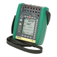
BEAMEX MC5-IS User Manual (164 pages)
NSTRINSICALLY SAFE MULTIFUNCTION CALIBRATOR
Brand:
BEAMEX
| Category:
Test Equipment
| Size: 2.98 MB
Table of Contents
Table of Contents
3
Introduction
10
About this Manual
10
Typographical Conventions
11
Unpacking and Inspection
11
MC5-IS Hardware
12
Operational Sections and Connections
12
The Upper Panel
13
The RS232 Connector on the Left Side of MC5-IS
14
The Front Panel
14
Memory
17
Batteries
18
About the Charger and the Charging Procedure
19
Removing/Replacing the Battery Pack
20
Support for Table Top Use
21
The Wrist Strap and the Neck Support Strap
21
MC5-IS Firmware
22
General Description
22
Startup Procedure
22
Basic Mode
23
Maintenance
23
Calibration Mode
23
Help Function
24
The User Interface
25
The Status Bar
25
The Function Key Bar
26
Menus
26
The Display Area
27
MC5-IS' Modularity and Options
31
Hardware Modules/Options
31
Other Connectable Devices
32
Firmware Options
32
Safety
33
Ex Information and Approvals
33
Safety Precautions and Warnings
34
General Warnings
34
Warnings Concerning the Use of Electrical Modules (E and ET)
34
General Warnings Concerning Pressure Measurement
35
Warnings Concerning High Pressure
36
Service
37
Firmware Update
37
Recalibrating MC5-IS
37
The Battery Charger
37
Cleaning MC5-IS
38
Cleaning the Contacts of the Internal Reference Junction Module
38
Part B, Startup and Basic Operation
39
Starting MC5-IS
40
Startup Procedure
40
Basic Mode, Defined
41
Measuring
43
Pressure Measurement
45
Using Internal Modules
45
Using External Modules
45
Zeroing a Pressure Module
46
Current Measurement
47
Voltage Measurement
48
Measuring Low Voltages
48
Measuring Voltages up to ±30 V
49
Resistance Measurement
50
Switch State Sensing
51
Limit Switch Test
52
Performing the Limit Switch Test
52
Table of Contents
53
Frequency Measurement
54
Pulse Counting
55
RTD Measurement (Temperature)
56
Thermocouple Measurement (Temperature)
57
Internal Reference Junction
57
External Reference Junction
57
Voltage Measurement
58
RTD Measurement (Temperature)
58
Special Measurements
59
Mathematical Special Measurements
60
Minimum Value
60
Maximum Value
60
Min/Max Value
60
Rate of Change
60
Special Filtering and Resolution
61
Deviation Measurement
61
Special Measurements Using Two Ports Simultaneously
62
Difference Measurement
62
Redundant Measurement
63
Generating/Simulating
64
General
64
Changing the Value of the Generated/Simulated Signal
65
Current Sink
66
Using the ET Module's Output Terminals
66
Using the E Module's Output Terminals
66
Voltage Generation
68
Generating Voltages between +10 V and -2.5 V
68
Low Voltage Generation
68
Frequency Generation
70
Pulse Generation
71
RTD and Resistance Simulation
72
Thermocouple Simulation
73
Internal Reference Junction
73
External Reference Junction
73
Special Generations
75
Opening the Step or Ramp Configuration Window
75
Stepping
76
Ramping
77
Alarm Limit Settings
79
Part C, Advanced Operation and Configurations
81
Configuring the Calibrator
82
Settings
82
Setting Time and Date
84
Advanced Utilities
85
Display Mode Settings
85
Scaling
86
Displaying Values in Percentage
87
Displaying Error Values
87
Transmitter/Switch Simulation
88
Transmitter Simulation
89
Switch Simulation
90
Data Logging
91
General
91
Configuring
91
Starting the Data Log
92
Viewing the Results
93
Transferring the Results to a Personal Computer
93
Additional Information
94
Things to Consider When Measuring Pressure
95
General
95
Pressure Type
95
Pressure Modules and Their Naming Conventions
96
Square Rooting
96
Thermocouple Measurement/Simulation, Connections and Troubleshooting
97
Internal Reference Junction
97
External Reference Junction
98
Error Situations
100
Resistance and RTD Measurement, Connections
101
4-Wire System
101
Using a Compensation Loop
102
2-Wire System
102
Current Measurement Parallel to a Test Diode, Connections
103
Parallel Functions in MC5-IS
104
Part D, Calibration
105
General
106
Phases of Instrument Calibration
107
As Found Calibration
108
Adjustment
108
As Left Calibration
109
Required Modules for Different Input/Output Signal Combinations
110
Calibrating an Instrument
112
Selecting the Instrument to be Calibrated
112
The Instrument Window
113
A Calibration Procedure Using MC5-IS
114
About Automatic Calibration
116
About Manual Calibration
116
Examples of Instrument Calibration
117
Pressure Transmitters
118
Temperature Sensors
120
Temperature Indicators and Recorders
122
Electrical Limit Switches
124
MC5-IS' Support for Instrument Adjustment
126
Maintaining MC5-IS' Instrument Database
127
Adding New Instruments
127
Editing Instrument Data
128
General Data Page
128
Instrument Input Page
129
Instrument Output Page
129
Calibration Settings Page
130
Calibration Instructions Page
131
Deleting Instruments
131
Viewing Calibration Results
132
Calibration Result Windows
133
How to Choose Which Calibration Run Is Viewed
133
Deleting Calibration Results
133
Appendix
135
Appendix 1, User Guide for Mc5-Is Hart Option
136
User Guide for MC5 HART Option
136
General
137
MC5-IS and HART
137
HART Instruments and Beamex's Calibration Database Software
138
Connecting MC5-IS and a HART Instrument
138
External Supply
138
Test Diode Connections
139
Using MC5-IS as a Hart Communicator
139
HART Communication Settings
140
HART and MC5-IS' Basic Mode
141
Connecting to a HART Instrument
141
Disconnecting a HART Instrument
142
Device Information
142
Device Settings
143
Trimming a HART Instrument in Basic Mode
143
Adding a HART Instrument to MC5-IS' Instrument Database
145
Calibrating a HART Instrument
146
Selecting the Instrument to be Calibrated
146
The Calibration Procedure
147
Trimming a HART Instrument in Calibration Mode
147
Technical Data
150
MC5-IS General Specifications
151
Modules
152
Pressure Modules (INT-IS & EXT-IS)
152
Temperature Electrical Module (ET)
153
RTD Measurement and Simulation
153
Thermocouple Measurement and Simulation
154
Reference Junction Module (RJ)
154
Electrical Module (E)
155
Quick Guide for the MC5 Datalog Viewer
156
Safety Information
160
Safety Information
161
Index
162
Advertisement
BEAMEX MC5-IS User Manual (46 pages)
Fieldbus Option for PROFIBUS PA
Brand:
BEAMEX
| Category:
Measuring Instruments
| Size: 0.63 MB
Table of Contents
Table of Contents
4
General
6
What Is Fieldbus
7
Unpacking and Inspection
7
Batteries
8
Charging the Batteries
8
Disposal of Waste Electrical and Electronic Equipment
9
Safety
10
Symbols Used
10
Ex Information and Approvals
10
Notes and Warnings
13
Service
15
Cleaning FI5-IS
15
The Battery Charger
15
Terminology
16
MC5-IS, FI5-IS and PROFIBUS PA
17
Calibration Procedure of a Fieldbus Instrument, General
17
Device Descriptions
19
Viewing Device Descriptions in MC5-IS
19
Device Description Sender
20
Fieldbus Instruments and Beamex's Calibration Database Software
21
Connecting to a PROFIBUS PA Instrument
22
Connections
23
Fieldbus and MC5-IS' Basic Mode
24
Connecting to a PROFIBUS PA Instrument
24
Fieldbus Window Setup Menu
27
Disconnect Device
27
Device Information
27
Transducer Block Information
28
Target Mode
29
Select Output
29
Trim Fieldbus Device
29
Add a Fieldbus Device to Database
30
Unit
32
Performing a Verifying Calibration
33
Selecting the Instrument
33
Doing the Verifying Calibration
34
Calibrating (Trimming, Adjusting) a Fieldbus Instrument
35
Advertisement
Related Products
BEAMEX MC4
BEAMEX MC5
BEAMEX MC6-Ex
BEAMEX MC6-WS
BEAMEX MC5P
BEAMEX MCS100
BEAMEX MC5-IS-FF
BEAMEX MC2-IS
BEAMEX MC6-T
BEAMEX MCS200
BEAMEX Categories
Test Equipment
Water Pump
Measuring Instruments
Controller
Desktop
More BEAMEX Manuals
Login
Sign In
OR
Sign in with Facebook
Sign in with Google
Upload manual
Upload from disk
Upload from URL