
Subscribe to Our Youtube Channel
Related Manuals for Thermo Scientific VF-F20-A


Summary of Contents for Thermo Scientific VF-F20-A
- Page 1 Vanquish Integral Fraction Collector FT VF-F20-A Operating Manual 4827.0601-EN Revision 1.0 • August 2022 *4827.6001-EN-1.0*...
- Page 2 Copyright © 2022 Thermo Fisher Scientific Inc. All rights reserved. Original Operation Manual The hardware descriptions in this manual revision refer to the device VF-F20-A Trademarks Acrobat, Adobe, and Adobe Reader are trademarks of Adobe Systems Incorporated. Microsoft and Windows are trademarks of Microsoft Corporation.
-
Page 3: Contacting Us
Contact Us on http://www.thermoscientific.com. Technical Assistance For technical support for HPLC products, contact your local Thermo Fisher Scientific support organization. For contact information, go to Contact Us on http://www.thermoscientific.com. Integral Fraction Collector FT (VF-F20-A) Operating Manual Page 3... - Page 4 Contacting Us Page 4 Integral Fraction Collector FT (VF-F20-A) Operating Manual...
-
Page 5: Table Of Contents
Solvent and Additive Information ................. 28 2.4.1 General Compatibility ................28 2.4.2 Allowed pH Ranges .................. 28 2.4.3 Allowed Concentrations ................29 2.4.4 Further Information ................. 29 Compliance Information ..................30 3 Device Overview ................32 Integral Fraction Collector FT (VF-F20-A) Operating Manual Page 5... - Page 6 5.7.1 Choosing the Needle Wash Liquid ............81 5.7.2 Connecting the Needle Wash Reservoir ..........81 Fraction Collection Valve ..................85 5.8.1 Port assignments of the Fraction Collection Valve ......... 85 Page 6 Integral Fraction Collector FT (VF-F20-A) Operating Manual...
- Page 7 Adjust to InVial Pusher Position ............. 135 Optimizing the Performance of the Device ............137 6.10 Shutting Down the Device .................. 138 6.10.1 Short-Term Shutdown (Interruption of operation) ....... 138 6.10.2 Long-Term Shutdown ................139 Integral Fraction Collector FT (VF-F20-A) Operating Manual Page 7...
- Page 8 7.17 Transporting or Shipping the Device ..............193 7.18 Slide-In Module ....................197 7.18.1 Removing the Slide-In Module .............. 197 7.18.2 Installing the Slide-In Module ............... 199 8 Troubleshooting ................202 General Information about Troubleshooting ............ 203 Page 8 Integral Fraction Collector FT (VF-F20-A) Operating Manual...
- Page 9 10.4 Consumables and Replacement Parts ..............228 11 Appendix ..................232 11.1 Compliance Information ..................233 11.1.1 Declarations of Conformity ..............233 11.1.2 WEEE Compliance .................. 234 11.1.3 FCC Compliance ..................235 12 Index ................... 236 Integral Fraction Collector FT (VF-F20-A) Operating Manual Page 9...
-
Page 10: Using This Manual
Using this Manual 1 Using this Manual This chapter provides information about this manual, the conventions used throughout the manual, and the reference documentation that is available in addition to this manual. Page 10 Integral Fraction Collector FT (VF-F20-A) Operating Manual... -
Page 11: About This Manual
The descriptions in this manual assume that the device is installed in the Vanquish system stack. If this is not the case, additional hardware is required and must be ordered separately. The information in this manual applies correspondingly. Integral Fraction Collector FT (VF-F20-A) Operating Manual Page 11... -
Page 12: Conventions
They appear in boxes and a note label identifies them. The label text appears in uppercase letters and in bold type. NOTICE Highlights information necessary to prevent damage to the device or invalid test results. Page 12 Integral Fraction Collector FT (VF-F20-A) Operating Manual... -
Page 13: Typographical Conventions
If not otherwise stated, the expressions left and right in this manual always refer to the viewpoint of a person that is facing the device from the front. Particularly Important Words Particularly important words in the main flow of text appear italicized. Integral Fraction Collector FT (VF-F20-A) Operating Manual Page 13... - Page 14 These include: • Table of contents entries • Index entries • Cross-references (in blue text), for example, to sections and figures Page 14 Integral Fraction Collector FT (VF-F20-A) Operating Manual...
-
Page 15: Reference Documentation
In Chromeleon 7, devices are called modules. • Quick Start Guide For information about the main elements of the user interface and step-by-step guidance through the most important workflows, refer to the Quick Start Guide. Integral Fraction Collector FT (VF-F20-A) Operating Manual Page 15... - Page 16 TIP The Chromeleon Help and documents are included in the software shipment. Third-Party Documentation Refer also to the user documentation provided by the manufacturers of third-party components and materials, for example, Safety Data Sheets (SDSs). Page 16 Integral Fraction Collector FT (VF-F20-A) Operating Manual...
- Page 17 • Using this Manual Integral Fraction Collector FT (VF-F20-A) Operating Manual Page 17...
-
Page 18: Safety
• Safety 2 Safety This chapter provides general and specific safety information and informs about the intended use of the device. Page 18 Integral Fraction Collector FT (VF-F20-A) Operating Manual... -
Page 19: Safety Symbols And Signal Words
Always keep the manual near the device for quick reference. • Save this manual and pass it on to any subsequent user. Read, understand, and comply with all safety messages and precautionary statements presented in this manual. Integral Fraction Collector FT (VF-F20-A) Operating Manual Page 19... -
Page 20: Safety Symbols On The Device
TIP An additional type label on the leak tray of the device indicates the serial number, part number, module name, and revision number. To facilitate device identification, have the information from this label available when communicating with Thermo Fisher Scientific. Page 20 Integral Fraction Collector FT (VF-F20-A) Operating Manual... -
Page 21: Intended Use
Regularly running calibration • Establishing shelf-life limits and following them for all consumables used with the system • Running the system according to the laboratory's verified and validated 'lab developed test' protocol Integral Fraction Collector FT (VF-F20-A) Operating Manual Page 21... -
Page 22: Safety Precautions
Thermo Fisher Scientific before proceeding. Safety Standard This device is a Safety Class I instrument (provided with terminal for protective grounding). The device has been manufactured and tested according to international safety standards. Page 22 Integral Fraction Collector FT (VF-F20-A) Operating Manual... -
Page 23: Qualification Of The Personnel
An eyewash facility and a sink should be available nearby. If any substance contacts your skin or eyes, wash the affected area and seek medical attention. Integral Fraction Collector FT (VF-F20-A) Operating Manual Page 23... -
Page 24: Electrical Safety Precautions
Do not place liquid reservoirs directly upon the device. Liquid might leak into the device and get into contact with electronic components causing a short circuit. Instead, place liquid reservoirs in the solvent rack that is available for the Vanquish system. Page 24 Integral Fraction Collector FT (VF-F20-A) Operating Manual... -
Page 25: General Residual Hazards
Wear personal protective equipment as required by the hazard and follow good laboratory practice. • Dispose of biohazardous waste in an environmentally safe manner that is consistent with local regulations. Follow a regulated, approved waste disposal program. Integral Fraction Collector FT (VF-F20-A) Operating Manual Page 25... - Page 26 Refer to the latest list of closures approved by Thermo Fisher Scientific. • Inspect vials for cracks or defects before use. Do not use cracked or damaged vials. Page 26 Integral Fraction Collector FT (VF-F20-A) Operating Manual...
-
Page 27: In Case Of Emergency
Prevent the generation of static electricity near the chromatography system. 2.3.6 In Case of Emergency WARNING—Safety Hazard In case of emergency, disconnect the device from the power line. Integral Fraction Collector FT (VF-F20-A) Operating Manual Page 27... -
Page 28: Solvent And Additive Information
• Mobile phases containing ammonium hydroxide: In rare cases, a shortened lifetime of reversed-phase (UHMW-PE) piston seals has been observed with high pH, ammonium hydroxide containing mobile phases and prolonged exposure. Page 28 Integral Fraction Collector FT (VF-F20-A) Operating Manual... -
Page 29: Allowed Concentrations
• Observe the general guidelines and recommendations on the use of solvents and additives in the chromatography system. Refer to Use of Solvents and Additives in the Vanquish System Operating Manual. Integral Fraction Collector FT (VF-F20-A) Operating Manual Page 29... -
Page 30: Compliance Information
Thermo Fisher Scientific or one of its authorized representatives. The device has been shipped from the manufacturing site in a safe condition. See also Compliance Information ( Page 233) Page 30 Integral Fraction Collector FT (VF-F20-A) Operating Manual... - Page 31 • Safety Integral Fraction Collector FT (VF-F20-A) Operating Manual Page 31...
-
Page 32: Device Overview
• Device Overview 3 Device Overview This chapter introduces you to the device and the main components. Page 32 Integral Fraction Collector FT (VF-F20-A) Operating Manual... -
Page 33: Integral Fraction Collector Features
Vanquish rack type identification • Flush function between fractions is available to improve recovery and minimize carry-over • Fraction collection can be triggered by both peak-based and time- based Integral Fraction Collector FT (VF-F20-A) Operating Manual Page 33... -
Page 34: Operating Principle
In flush position the flush buffer loop filled with flush solvent is Page 34 Integral Fraction Collector FT (VF-F20-A) Operating Manual... - Page 35 The HPLC pump flow supplies clean mobile phase to rinse the inner surface of the needle to the wash waste. Integral Fraction Collector FT (VF-F20-A) Operating Manual Page 35...
- Page 36 Note: Waste drainage is routed to a waste container. The following figures illustrate how the device operates for collecting fractions, flushing between fractions of one run, washing the needle externally between runs, rinsing the needle internally between runs and Page 36 Integral Fraction Collector FT (VF-F20-A) Operating Manual...
- Page 37 The fraction collection valve is switched between three different positions depending on the operation: Figure 3: Fraction collection with fraction collection valve in collect position Figure 4: Flush with fraction collection valve in flush position Integral Fraction Collector FT (VF-F20-A) Operating Manual Page 37...
- Page 38 • Device Overview Figure 5: External Needle Wash in needle wash port with fraction collection valve in waste position Page 38 Integral Fraction Collector FT (VF-F20-A) Operating Manual...
- Page 39 Several draw and dispense strokes are executed during the purge flush pump operation to fill the flow path from flush solvent container, flush pump to flush buffer loop with fresh flush solvent. Integral Fraction Collector FT (VF-F20-A) Operating Manual Page 39...
- Page 40 • Device Overview Figure 7: Draw of fresh flush solvent from solvent container to fill flush pump Figure 8: Dispense liquid out to flush buffer loop and drain to waste Page 40 Integral Fraction Collector FT (VF-F20-A) Operating Manual...
-
Page 41: Interior Components
Keypad with status indicators Fraction collector compartment with carousel Removable front plate Front leak tray Type label, indicating the part number, module name, and serial number Right interior side with flow components Integral Fraction Collector FT (VF-F20-A) Operating Manual Page 41... - Page 42 1 and port 4) Guide hole for wash port outlet Fraction collection valve tubing and condensation tubing Front leak sensor Air bubble sensor (installed around the tubing and located behind the panel) Page 42 Integral Fraction Collector FT (VF-F20-A) Operating Manual...
-
Page 43: Fraction Collector Compartment
The drain system includes a drain pump and one inlet tubing going to the rear side of the device to drain out condensation water accumulated inside the fraction collector compartment at fixed interval. Integral Fraction Collector FT (VF-F20-A) Operating Manual Page 43... -
Page 44: Carousel
Vanquish rack type 2D barcode is present. During operation, the barcode reader performs an inventory scan and reads the Vanquish rack type barcode if present. The barcode reader Page 44 Integral Fraction Collector FT (VF-F20-A) Operating Manual... -
Page 45: Condensation Drainage
Vanquish system. If the liquid is drained and the sensor gets dry, then the drain pump will resume idle state. For more details, see Messages (Code 9004) ( page 205). Integral Fraction Collector FT (VF-F20-A) Operating Manual Page 45... -
Page 46: Leak Detection
Follow the instructions in this manual to find and eliminate the source for the leakage. For more details, see Resolving Front Leakage ( page 212). Page 46 Integral Fraction Collector FT (VF-F20-A) Operating Manual... -
Page 47: Operation
Operating Manual. Details on control and operation of the device are available in the Chromeleon Help. A keypad is available inside the device, allowing you to perform certain basic functions directly from the device. Integral Fraction Collector FT (VF-F20-A) Operating Manual Page 47... - Page 48 • Device Overview Page 48 Integral Fraction Collector FT (VF-F20-A) Operating Manual...
-
Page 49: Unpacking And Transport
• Unpacking and Transport 4 Unpacking and Transport This chapter provides information for unpacking the device and informs you about the scope of delivery. Integral Fraction Collector FT (VF-F20-A) Operating Manual Page 49... -
Page 50: Unpacking The Device
2. Remove the ship kit from the shipping container. 3. Remove the device from the shipping container: Grasp the device by the carrying handles. Slowly and carefully, lift the device out of the shipping container. Page 50 Integral Fraction Collector FT (VF-F20-A) Operating Manual... - Page 51 TIP Keep the shipping container, the carrying handles with the attachment screws, and all packing material. These items will be needed if the device is transported to a new location or shipped. Integral Fraction Collector FT (VF-F20-A) Operating Manual Page 51...
- Page 52 2. Remove the shipping lock fixing needle arm. Unscrew three screws on the shipping lock completely with the screwdriver, then remove the shipping lock. Figure 16: Remove needle arm shipping lock Page 52 Integral Fraction Collector FT (VF-F20-A) Operating Manual...
- Page 53 • Unpacking and Transport 3. Remove the shipping lock fixing carousel. Figure 17: Remove carousel shipping lock Integral Fraction Collector FT (VF-F20-A) Operating Manual Page 53...
-
Page 54: Scope Of Delivery
The following items are included in the delivery: • Fraction collector • Ship kit For details about the kit content, see Ship Kit ( page 224). • Safety notes and test report Page 54 Integral Fraction Collector FT (VF-F20-A) Operating Manual... -
Page 55: Installation
5 Installation This chapter specifies the requirements for the installation site and describes how to set up, install, and configure the device in the Vanquish system and in the chromatography software. Integral Fraction Collector FT (VF-F20-A) Operating Manual Page 55... -
Page 56: Safety Guidelines For Installation
Always unplug the power cord before starting repair work inside the device. • If you were instructed to remove any housing covers or panels, do mot connect the power cord to the device while the cover or panels are removed. Page 56 Integral Fraction Collector FT (VF-F20-A) Operating Manual... -
Page 57: Installing The Device
Operating Instructions. The manual provides information about the required materials and detailed instructions. 7. Recommended: Perform Operational Qualification. The qualification kit includes all materials required for the qualification and detailed instructions. Integral Fraction Collector FT (VF-F20-A) Operating Manual Page 57... - Page 58 TIP When the power is turned off to the device, the left front door of the device is opened automatically for proper ventilation of the fraction collector compartment and cannot be closed while the power is turned off. Page 58 Integral Fraction Collector FT (VF-F20-A) Operating Manual...
-
Page 59: Site Requirements
If you were instructed to remove any covers or panels, do not connect the power cord to the device while the cover or panels are removed. Integral Fraction Collector FT (VF-F20-A) Operating Manual Page 59... -
Page 60: Power Cord
Use the power cords provided by Thermo Fisher Scientific only for the purpose for which they are intended. Do not use them for any other purpose, for example, for connecting other instruments. Page 60 Integral Fraction Collector FT (VF-F20-A) Operating Manual... -
Page 61: Condensation
If you suspect that condensation is present, allow the device to warm up to room temperature. This may take several hours. Wait until the condensation is gone completely before connecting the device to the power line. Integral Fraction Collector FT (VF-F20-A) Operating Manual Page 61... -
Page 62: Accessing The Interior Components
When the device is turned on, the left front door can be closed. If a power failure occurs or if the power cord is disconnected while the device has been turned on, the mechanism opens the left front door automatically. Page 62 Integral Fraction Collector FT (VF-F20-A) Operating Manual... -
Page 63: Setting Up The Hardware
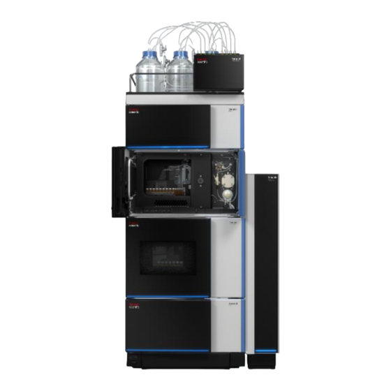
System Base. A second Solvent Rack can be added optionally. Figure 19: Vanquish system, standard configuration (examples): left - one stack, right - two stacks Description Description Solvent Rack Pump Detector System Base Fraction Collector Column Compartment Autosampler Integral Fraction Collector FT (VF-F20-A) Operating Manual Page 63... - Page 64 For instructions how to set up the system stack, refer to the Vanquish System Operating Manual. Page 64 Integral Fraction Collector FT (VF-F20-A) Operating Manual...
-
Page 65: Connecting The Device
Allow exchange of digital signals with external instruments Each digital I/O port provides one input and one relay output. For debugging purposes only. USB hub ("A" type connector) Allows connection to other modules in the Vanquish system Integral Fraction Collector FT (VF-F20-A) Operating Manual Page 65... - Page 66 If the USB ports are used for any other purpose, Thermo Fisher Scientific cannot ensure proper functionality. Connecting the USB and system interlink cables Figure 21: USB and system interlink cable connections Page 66 Integral Fraction Collector FT (VF-F20-A) Operating Manual...
- Page 67 This may take several hours. Wait until the condensation is completely gone before proceeding. 5. Connect the free end of the power cord to an appropriate power source. Integral Fraction Collector FT (VF-F20-A) Operating Manual Page 67...
-
Page 68: Setting Up The Flow Connections
When you install devices or components to the system, always flush them to waste before connecting them in the system flow path. To flush the Vanquish modules, follow the instructions in the Vanquish System Operating Manual. Page 68 Integral Fraction Collector FT (VF-F20-A) Operating Manual... -
Page 69: Guiding Capillaries And Tubing Through The System
The tubing chase provides four tubing guides. Each guide can hold up to three tubing or lines. In each module, push the tubing (or line) into the appropriate guide. Integral Fraction Collector FT (VF-F20-A) Operating Manual Page 69... - Page 70 Route flow connections from one module to the next module in the Vanquish system through the appropriate guide hole or capillary clip when instructed to do so in the manual. Page 70 Integral Fraction Collector FT (VF-F20-A) Operating Manual...
-
Page 71: Connecting Fittings, Capillaries, And Tubing
A detector waste line is shipped with HPLC detector. However, if a fraction collector is installed in the HPLC system, the waste line will be used to connect with the Y-connector outlet of the fraction collector and routed to waste reservoir. Integral Fraction Collector FT (VF-F20-A) Operating Manual Page 71... - Page 72 0.10 x 300 mm, MP35N Diode Array Detector FG • • 0.10 x 350 mm, MP35N Variable Wavelength Detector F • • 0.10 x 450 mm, MP35N Fluorescence Detector F & D-PMT Page 72 Integral Fraction Collector FT (VF-F20-A) Operating Manual...
- Page 73 0.13 x 300 mm, SST Multiple Wavelength Detector CG • • 0.13 x 350 mm, SST Variable Wavelength Detector C • • 0.13 x 450 mm, SST Fluorescence Detector C & D-PMT Integral Fraction Collector FT (VF-F20-A) Operating Manual Page 73...
- Page 74 Integral Fraction Collector FT Flush buffer loop for up to 5 mL/min, 50 µL, PEEK Flush buffer loop for 5 - 10 mL/min, 100 µL, Optional, needs be ordered separately PEEK Waste fluidic Detector Page 74 Integral Fraction Collector FT (VF-F20-A) Operating Manual...
- Page 75 MP35N • 0.5 – 1 mL/min: 0.25 x 1500 mm, MP35N • 1 - 2 mL/min: 0.5 x 800 mm, PEEK • 2 - 10 mL/min: 1 x 1000 mm, PEEK Integral Fraction Collector FT (VF-F20-A) Operating Manual Page 75...
- Page 76 Depending on flow rate Integral Fraction Collector FT Needle capillary for up to 5 mL/min, 0.18 mm, PEEK Needle capillary for 5 – 10 mL/min, 0.25 Optional, needs be ordered separately mm, PEEK Page 76 Integral Fraction Collector FT (VF-F20-A) Operating Manual...
- Page 77 Viper capillaries only when the system pressure is down to zero. Figure 26: Viper fitting with knurl Description Knurl Capillary Slot 1. Insert the Viper capillary into the connection port. Integral Fraction Collector FT (VF-F20-A) Operating Manual Page 77...
-
Page 78: Guiding Liquids To Waste
Vanquish system base. On the system base, route the waste line through the dedicated waste outlet and connect the waste line to the waste container as described in the Vanquish System Operating Manual. Page 78 Integral Fraction Collector FT (VF-F20-A) Operating Manual... - Page 79 The waste line should go straight to the system base and to waste. Make sure that the line is positioned straight in the tubing guides. Integral Fraction Collector FT (VF-F20-A) Operating Manual Page 79...
-
Page 80: Needle Wash System
Needle wash inlet line (up to needle wash reservoir) Needle wash port Needle wash outlet line (from wash pump outlet to needle wash port) Needle wash waste line Needle wash pump (installed behind the panel) Page 80 Integral Fraction Collector FT (VF-F20-A) Operating Manual... -
Page 81: Choosing The Needle Wash Liquid
81). Follow these steps Setting up the needle wash system comprises the following steps: 1. Setting up the needle wash line in the fraction collector. 2. Connecting the needle wash reservoir. Integral Fraction Collector FT (VF-F20-A) Operating Manual Page 81... - Page 82 2. Route the needle wash inlet line from the device to the solvent rack, through the tubing guides of the modules and the guide hole in the solvent rack. Figure : Guide hole and tubing guides in the solvent rack Page 82 Integral Fraction Collector FT (VF-F20-A) Operating Manual...
- Page 83 Figure 30: Securing the needle wash line with the reservoir cap Description Needle wash inlet line Retaining guide (1/8’’) Reservoir cap Cap plugs 2. Fill the needle wash reservoir with needle wash liquid. Mind the requirements outlined in the previous section. Integral Fraction Collector FT (VF-F20-A) Operating Manual Page 83...
- Page 84 Chromeleon to fill the needle wash port with the fresh needle wash liquid. During purging, the needle wash port is flushed continuously until the fresh needle wash liquid is present. Page 84 Integral Fraction Collector FT (VF-F20-A) Operating Manual...
-
Page 85: Fraction Collection Valve
Y-connector (pre-installed) (pre-installed) to needle Capillary Central port, inlet from detector to Y-connector via air to flush solvent bubble sensor (pre-installed) to flush buffer loop to flush pump (pre-installed) (pre-installed) Integral Fraction Collector FT (VF-F20-A) Operating Manual Page 85... -
Page 86: Flush System
Place the frit in the filter holder (bottom part). b) Make sure that the frit is in a level position. c) Screw the filter top to the filter bottom. Page 86 Integral Fraction Collector FT (VF-F20-A) Operating Manual... - Page 87 Setting up the Flush Solvent Tubing in the Fraction Collector 1. Connect the flush solvent tubing to the fraction collection valve port 7 and push the tubing into the tubing holder. Integral Fraction Collector FT (VF-F20-A) Operating Manual Page 87...
- Page 88 Guide hole Not to be used for wash liquid line; reserved for other tubing Tubing guide for wash liquid line Not to be used for wash liquid line; reserved for other tubing Page 88 Integral Fraction Collector FT (VF-F20-A) Operating Manual...
- Page 89 5. Place the flush solvent reservoir in the solvent rack. Position the solvent lines straight in the flush solvent reservoir and tubing guides. Integral Fraction Collector FT (VF-F20-A) Operating Manual Page 89...
-
Page 90: Connecting The Delay Capillary
1. Remove the detector waste line if it has been installed onto detector flow cell outlet or the outlet (OUT) on the flow cell connection unit. Figure 36: Removing the detector waste line Description Detector waste line Page 90 Integral Fraction Collector FT (VF-F20-A) Operating Manual... -
Page 91: Connecting The Flush Buffer Loop
Meanwhile, the installed flush buffer loop must be compatible with specific needle capillary. See below table for details. Flow rate Needle Capillary Flush Buffer Loop Remark Volume 0.05 – 5 mL/min 0.18 mm 50 µL Included in ship kit Integral Fraction Collector FT (VF-F20-A) Operating Manual Page 91... - Page 92 Follow these steps Install the needle capillary. See Replacing the Needle Capillary ( page 172). NOTICE Make sure no extra stress, damage and kink defects for needle capillary during the installation process. Page 92 Integral Fraction Collector FT (VF-F20-A) Operating Manual...
-
Page 93: Turning On The Device
Pressing the system power button will not be sufficient to turn off the power to the device completely. For power on/off control during device operation, see Power On/Off Control ( page 104). Integral Fraction Collector FT (VF-F20-A) Operating Manual Page 93... -
Page 94: Setting Up The Device In The Software
ID 0.18 mm or ID 0.25 mm. The default needle capillary installed in the device is ID 0.18 mm. 2. In Chromeleon Console click Command icon or press F8. Figure 38: Selecting the Command configuration page Page 94 Integral Fraction Collector FT (VF-F20-A) Operating Manual... - Page 95 The capillary marker on the needle capillary indicates the dimensions. Figure 39: Set the type of needle capillary. For more details, see Optional Accessories ( Page 226). Integral Fraction Collector FT (VF-F20-A) Operating Manual Page 95...
-
Page 96: Operation
• Operation • 6 Operation This chapter describes the elements for device control, provides information for routine operation and for shutdown. Page 96 Integral Fraction Collector FT (VF-F20-A) Operating Manual... -
Page 97: Introduction To This Chapter
Operating Manual. Details on control and operation of the device are available in the Chromeleon Help. Software descriptions in this manual refer to Chromeleon 7. Terminology may be different to that of other software versions. Integral Fraction Collector FT (VF-F20-A) Operating Manual Page 97... -
Page 98: Safety Guidelines For Operation
If a spill occurs inside the device, turn the device power off. Clean up the spill and leave the device door open. Allow sufficient time for the spill to dry and any vapors to disperse before putting the device back into use. Page 98 Integral Fraction Collector FT (VF-F20-A) Operating Manual... - Page 99 If the device is turned off, for example, after a power failure, stop the pump flow and wait until the pressure is down to zero before turning on the device other modules again. Integral Fraction Collector FT (VF-F20-A) Operating Manual Page 99...
-
Page 100: Control Elements
The STATUS LED provides a quick visual check of the operational status of the device. When the doors are closed, the LED bar on the front side indicates the operational status. For status details, see Status Indicators ( page 102). Page 100 Integral Fraction Collector FT (VF-F20-A) Operating Manual... - Page 101 The wash cycle is performed with the wash settings as defined in Chromeleon. After the needle wash cycle, the needle moves to the parking position if the left door is open. Integral Fraction Collector FT (VF-F20-A) Operating Manual Page 101...
-
Page 102: Status Indicators
The power to the device is turned off. Dimmed The doors of the device are open. Yellow, flashing The power to the device is turned on, but the device is not slowly connected in the Chromeleon software. Page 102 Integral Fraction Collector FT (VF-F20-A) Operating Manual... - Page 103 The power to the device is turned off. Green The device is functioning properly. A problem or error has occurred. For the related message, check the Chromeleon Audit Trail. For remedial action, see Troubleshooting ( page 202). Integral Fraction Collector FT (VF-F20-A) Operating Manual Page 103...
-
Page 104: Power On/Off Control
At the end of the power up, the device sets the fraction collection valve to waste position and needle unit to home position. If the compartment door(left) is open, then the needle unit moves to parking position to leave customers manual operation space. Page 104 Integral Fraction Collector FT (VF-F20-A) Operating Manual... -
Page 105: Preparing The Device For Operation
Load the carousel with well plates or racks with empty. NOTICE Before starting a sample or sequence, verify that the rack types set in Chromeleon match the rack types in the fraction collector compartment. Integral Fraction Collector FT (VF-F20-A) Operating Manual Page 105... - Page 106 Turning on the lamp (or lamps) in the UV/VIS detector. • Monitoring the pump pressure and pressure ripple and checking that the pressure is stable and the ripple within reasonable limits for the application. Page 106 Integral Fraction Collector FT (VF-F20-A) Operating Manual...
-
Page 107: Thermostatting The Fraction Collector Compartment
(G), blue (B) and yellow (Y). For further information on the sample compartment in general, the carousel as well as the rack type identification, see Fraction Collector Compartment ( Page 43). Integral Fraction Collector FT (VF-F20-A) Operating Manual Page 107... - Page 108 TIP For ordering information of sample racks and well plates for the device, refer to the re-ordering information that is included in the ship kit shipped with the Vanquish Split Sampler. Page 108 Integral Fraction Collector FT (VF-F20-A) Operating Manual...
- Page 109 2. Position the sample rack or well plate in the selected segment with A1 being in the top left sample position. The sample rack or well plate must sit in the alignment frame and rest on the alignment points of the segment. Integral Fraction Collector FT (VF-F20-A) Operating Manual Page 109...
- Page 110 5. Continue as required by the sample racks or well plates that are installed in the carousel. See Rack Type Settings ( Page 111). Page 110 Integral Fraction Collector FT (VF-F20-A) Operating Manual...
-
Page 111: Rack Type Settings
Rack type identification enables auto needle height default setting. However, it is also allowed to manually set specific needle heights with settable range defined by the system. Integral Fraction Collector FT (VF-F20-A) Operating Manual Page 111... - Page 112 • Operation Below table is listed with auto needle height default values and settable ranges for different rack types that are provided by Thermo Scientific. AboveVial Mode InVial Mode Default Needle Default Needle Needle Height Needle Height Height settable Height...
-
Page 113: Important Operating Parameters
The default temperature is set to 25 °C (Temperature Nominal = 25). For details, see Thermostatting the Fraction Collector Compartment ( page 107). Integral Fraction Collector FT (VF-F20-A) Operating Manual Page 113... - Page 114 If the pump motor is off or the flow rate is set to 0 mL/min and Internal Needle Rinse is triggered an error message will be issued (Code 9055. Internal needle rinse failed. Pump speed is 0.). Page 114 Integral Fraction Collector FT (VF-F20-A) Operating Manual...
- Page 115 No Rinse in Chromeleon. Light control The fraction collector compartment light is turned on as a standard when the device is shipped (Light = On). Integral Fraction Collector FT (VF-F20-A) Operating Manual Page 115...
- Page 116 Different parameters as explained in the next rows can be set to change the needle height in different needle positioning mode (In Vial or Above Vial) in Instrument Method Wizard or Editor. Page 116 Integral Fraction Collector FT (VF-F20-A) Operating Manual...
- Page 117 The puncture offset is defaulted to 0. Leak detection Leak detection is enabled as a standard when the device is shipped (Leak Sensor Mode = Enabled). This is the preferred setting. Integral Fraction Collector FT (VF-F20-A) Operating Manual Page 117...
- Page 118 Select this check box to return to the first tube after the last tube is filled. If this check box is cleared, the Chromeleon Queue will be aborted when the last tube is reached. Page 118 Integral Fraction Collector FT (VF-F20-A) Operating Manual...
- Page 119 Chromeleon sequence view and associate the values to StartFractionPosition and FractionRange properties in the Script Editor of Chromeleon Console. Refer to Chromeleon Online Help for details. Integral Fraction Collector FT (VF-F20-A) Operating Manual Page 119...
-
Page 120: Delay Volume Determination (Dvd)
The correct delay time ensures optimal fraction collection of the target peak with high recovery and low carry over. Figure 43: Fraction collection valve located at waste position when running delay volume determination Page 120 Integral Fraction Collector FT (VF-F20-A) Operating Manual... -
Page 121: When To Perform Dvd Function
• Never move or uninstall the fitting on port 3 of fraction collection valve. The flow path on this port have been performed calibration during in-house production process or in-field service. Integral Fraction Collector FT (VF-F20-A) Operating Manual Page 121... -
Page 122: How To Perform Dvd Function
The DVD capillary connects autosampler and detector directly. • Make sure the column is bypassed. 5. After the DVD is performed, users can check the measured Delay Volume in Chromeleon > FC ePanel tab > More Options dialog. Page 122 Integral Fraction Collector FT (VF-F20-A) Operating Manual... - Page 123 6. After the successful DVD, the method specific delay volume and delay time will be automatically updated in the Instrument Method Wizard. The method specific delay time considers the set pump flow rate. Figure 45: Method specific delay volume and time Integral Fraction Collector FT (VF-F20-A) Operating Manual Page 123...
-
Page 124: Delay Volume Capillary Drop Down Menu
Delay Capillary IDxL: • 100 µm x 350 mm • 180 µm x 350 mm • 180 µm x 1200 mm • 250 µm x 1500 mm • 500 µm x 800 mm Page 124 Integral Fraction Collector FT (VF-F20-A) Operating Manual... -
Page 125: Vanquish Modules Enabling Delay Volume Determination
VF-A40-A, VC-A12-A, VC-A13-A Charger VH-A90-A Detector Diode Array VH-D10-A, VF-D11-A, VC-D11-A Variable Wavelength VC-D40-A, VF-D40-A Multi-Wavelength VC-D12-A Fraction Collector VF-F20-A Delay volume determination is not enabled by the detector model numbers below. Integral Fraction Collector FT (VF-F20-A) Operating Manual Page 125... -
Page 126: Vanquish Detector Flow Cells Enabling Delay Volume Determination
Semi-micro flow cell, SST, 7mm VC-D40 VF-D11 6083.0510 Standard flow cell, SST, 10mm VC-D11 VC-D12 VF-D11 6083.0520 Semi-analytical flow cell, SST, 7mm VC-D11 VC-D12 VF-D11 6083.0530 Semi-micro flow cell, SST, 7mm VC-D11 VC-D12 Page 126 Integral Fraction Collector FT (VF-F20-A) Operating Manual... -
Page 127: Delay Volume Calculator
Number with VF-D40 Semi-preparative flow cell, biocompatible, PEEK, 0.4 6074.0320 VC-D40 VF-D40 6077.0200 Standard flow cell, biocompatible, PEEK, 10 mm VC-D40 VF-D40 6077.0300 Semi-micro flow cell, biocompatible, PEEK, 7 mm VC-D40 Integral Fraction Collector FT (VF-F20-A) Operating Manual Page 127... - Page 128 It is recommended to use computer desktop as directory for quickest access. For more details please read the release notes provided with the Vanquish Fraction Collector software package and/or Chromeleon release. Page 128 Integral Fraction Collector FT (VF-F20-A) Operating Manual...
- Page 129 5. Define the Detector Response Time to be applied in the instrument method. 6. The calculator displays the resulting Delay Time and Delay Volume in the Method Specific Delay section. Integral Fraction Collector FT (VF-F20-A) Operating Manual Page 129...
- Page 130 8. Create or open the desired instrument method and paste the value on the Collecting Options page in the Method Specific Delay section. Figure 48: Collecting Options page in the instrument method Page 130 Integral Fraction Collector FT (VF-F20-A) Operating Manual...
- Page 131 • Operation Figure 49: Pump Flow Rate on Flow Gradient page in instrument method Figure 50: Detector Response Time in Channel Settings in Instrument Method Integral Fraction Collector FT (VF-F20-A) Operating Manual Page 131...
-
Page 132: Vial Pusher Positions
Chromeleon will issue a message to remind users to adjust to correct position. For more information, refer to Chromeleon Help. Figure 51: left - AboveVial pusher position, right - InVial pusher position Page 132 Integral Fraction Collector FT (VF-F20-A) Operating Manual... -
Page 133: Adjust To Abovevial Pusher Position
Follow these steps 1. Raise the lock pin upwards by hand. The pusher will be moved up accordingly. Figure 52: Moving the pusher up by hand Description Description Lock tab U-shape slot Integral Fraction Collector FT (VF-F20-A) Operating Manual Page 133... - Page 134 3. Release the lock pin and check that the needle tip protrudes out of the pusher. Then close the left front door. Figure 54: Checking the needle tip below the pusher 4. Verify the correct pusher position is set correctly in Chromeleon. Page 134 Integral Fraction Collector FT (VF-F20-A) Operating Manual...
-
Page 135: Adjust To Invial Pusher Position
2. Release the lock pin. The pusher is released to InVial position. 3. Physically check that the needle tip does not protrude out of the pusher and close the left front door. Integral Fraction Collector FT (VF-F20-A) Operating Manual Page 135... - Page 136 • Operation Figure 56: Checking the needle tip higher than the pusher tip 4. Verify the correct pusher position is set correctly in Chromeleon. Page 136 Integral Fraction Collector FT (VF-F20-A) Operating Manual...
-
Page 137: Optimizing The Performance Of The Device
Predictive Performance ( page 151). • Observe the general guidelines and recommendations in the Vanquish System Operating Manual on the use of solvents and additives in the chromatography system. Integral Fraction Collector FT (VF-F20-A) Operating Manual Page 137... -
Page 138: Shutting Down The Device
If the pressure falls below the lower limit, the pump stops the flow. • Set the injection valve in the autosampler to the Inject position. • Set the fraction collection valve in the device to the Waste position. Page 138 Integral Fraction Collector FT (VF-F20-A) Operating Manual... -
Page 139: Long-Term Shutdown
(50:50) to prevent salt buildup in the fluidics. If the solvents in the device are not miscible with water, use an appropriate intermediate solvent. Integral Fraction Collector FT (VF-F20-A) Operating Manual Page 139... - Page 140 Remove the sample racks and sample containers from the fraction collector compartment. c) If condensation or spilled samples are present in the fraction collector compartment, clean and decontaminate the fraction Page 140 Integral Fraction Collector FT (VF-F20-A) Operating Manual...
- Page 141 4. Turn on the pump flow and flush the flow path of the device. 5. Before starting an analysis, let the device equilibrate and be sure that it is ready for operation. see Preparing the Device for Operation ( page 105). Integral Fraction Collector FT (VF-F20-A) Operating Manual Page 141...
-
Page 142: Maintenance And Service
• Maintenance and Service 7 Maintenance and Service This chapter describes the routine maintenance and the service procedures that the user may perform. Page 142 Integral Fraction Collector FT (VF-F20-A) Operating Manual... -
Page 143: Introduction To Maintenance And Service
However, it is possible to remove a door if this should ever be required for a specific reason or procedure. If you need to remove a door, follow the related steps in Replacing the Doors ( page 191). Integral Fraction Collector FT (VF-F20-A) Operating Manual Page 143... -
Page 144: Safety Guidelines For Maintenance And Service
• Wear appropriate protective equipment and follow good laboratory practice. • Before starting maintenance or repair procedures, flush out harmful substances with an appropriate solvent. Page 144 Integral Fraction Collector FT (VF-F20-A) Operating Manual... - Page 145 Always unplug the power cord before starting repair work inside the device. • If you were instructed to remove any housing covers or panels, do not connect the power cord to the device while the cover or panels are removed. Integral Fraction Collector FT (VF-F20-A) Operating Manual Page 145...
- Page 146 TIP When the power is turned off to the device, the left front door of the device is opened automatically for proper ventilation of the fraction collector compartment and cannot be closed while the power is turned off. Page 146 Integral Fraction Collector FT (VF-F20-A) Operating Manual...
-
Page 147: General Rules For Maintenance And Service
Always install caps onto capillaries and plugs to open flow connections to protect them from contamination. • If you need to return the device for depot repair, follow the instructions in Transporting or Shipping the Device ( page 193). Integral Fraction Collector FT (VF-F20-A) Operating Manual Page 147... -
Page 148: Routine And Preventive Maintenance
Replace the needle wash liquid and flush solvent in the needle wash and flush solvent reservoirs regularly, approximately every 1 or 2 weeks. See Needle Wash Liquid Guidelines ( Page 159). Page 148 Integral Fraction Collector FT (VF-F20-A) Operating Manual... -
Page 149: Cleaning Or Decontaminating The Device
Parts required • Suitable cleaning detergent (or disinfectant) • Purified water • Lint-free cloths or wipes Integral Fraction Collector FT (VF-F20-A) Operating Manual Page 149... - Page 150 3. Turn off the power to the device and disconnect the power cord from the power source. 4. Secure the needle drive with needle arm shipping lock by fixing three screws. See Predictive Performance ( page 151) Page 150 Integral Fraction Collector FT (VF-F20-A) Operating Manual...
-
Page 151: Predictive Performance
Some counters can be reset to zero after the required action was performed. To keep the Predictive Performance information up-to-date, consider resetting the counter when a maintenance, service, or qualification procedure has been performed. For more information, refer to the Chromeleon Help. Integral Fraction Collector FT (VF-F20-A) Operating Manual Page 151... - Page 152 The list shows the Predictive Performance counter for the device in Chromeleon. Consider resetting the parameter after performing the related maintenance procedure: Predictive Performance To perform Command ServiceDone After annual maintenance by service personnel. Page 152 Integral Fraction Collector FT (VF-F20-A) Operating Manual...
-
Page 153: Before Maintenance
5. Empty the drain pump: Leave the drain pump turned on until no condensing water is present in the waste tubing of the drain pump. Then turn off the drain pump. Integral Fraction Collector FT (VF-F20-A) Operating Manual Page 153... -
Page 154: Securing The Needle Drive
When the device is powered off, the needle drive may move inside the fraction collector compartment when the device is tilted, moved from one place to another place. Page 154 Integral Fraction Collector FT (VF-F20-A) Operating Manual... -
Page 155: Removing The Front Plate
1. Loosen the two screws that attaches the removable front plate with the screwdriver. The screws shall remain in the front plate. Figure 57: Loosening the two screws in front plate Integral Fraction Collector FT (VF-F20-A) Operating Manual Page 155... - Page 156 Figure 58: Pulling out the front plate 3. Pull out the cable connector from the front plate which is located at the top. Disconnect the cable connector. Figure 59: Disconnecting the cable connector Page 156 Integral Fraction Collector FT (VF-F20-A) Operating Manual...
- Page 157 5. Align the removable front plate into place and push it slightly downward to the bottom. Figure 61: Putting front plate into place by slightly pushing downward to the bottom Integral Fraction Collector FT (VF-F20-A) Operating Manual Page 157...
- Page 158 • Maintenance and Service 6. Tighten the attachment screw to fix the front plate with the screwdriver. Figure 62: Tightening two screws and secure the front plate Page 158 Integral Fraction Collector FT (VF-F20-A) Operating Manual...
-
Page 159: Needle Wash Lines
In Chromeleon, purge the needle wash system to fill up the needle wash port with the fresh needle wash liquid. During purging, the needle wash port and the fluid path is flushed continuously until the fresh needle wash liquid is present. Integral Fraction Collector FT (VF-F20-A) Operating Manual Page 159... -
Page 160: Replacing Needle Wash Lines
FC tab for the device to empty the needle wash system. 4. Turn off the device with its main power switch. NOTICE The device shall be powered off while removing or replacing the front plate. Page 160 Integral Fraction Collector FT (VF-F20-A) Operating Manual... - Page 161 Needle wash port inlet Needle wash port The slot on the housing Needle wash outlet line Needle wash pump outlet 3. Re-install the front plate. See Removing the Front Plate ( Page 155). Integral Fraction Collector FT (VF-F20-A) Operating Manual Page 161...
-
Page 162: Performing A Needle Wash Cycle
Purge the needle wash system to fill the needle wash port with fresh needle wash liquid, for example after replacing the needle wash liquid. In Chromeleon, select the Purge Needle Wash button on the ePanel FC tab. Page 162 Integral Fraction Collector FT (VF-F20-A) Operating Manual... - Page 163 FC tab. After the needle wash cycle has been completed, the needle moves up and stays at needle wash port or moves to parking position if the compartment door is open. Integral Fraction Collector FT (VF-F20-A) Operating Manual Page 163...
-
Page 164: Flush System
During purging, the flush pump and flush buffer loop are washed continuously until all flush purge lines are filled with the fresh flush solvent. See Performing A Flush Purge Cycle ( page 171). Page 164 Integral Fraction Collector FT (VF-F20-A) Operating Manual... -
Page 165: Replacing Flush Purge Lines
Flush buffer loop (from fraction collection valve port 1 to port 4) Flush waste tubing (from fraction collection valve port 5 to Y- connector) Figure 64: Configuration of flush purge lines Integral Fraction Collector FT (VF-F20-A) Operating Manual Page 165... - Page 166 The knurl needs to be fit with Viper fitting first before tightening or loosening Page 166 Integral Fraction Collector FT (VF-F20-A) Operating Manual...
- Page 167 3. Disconnect from the flush pump by unscrewing the fitting. 4. Disconnect the Viper fitting from port 8 of fraction collection valve with the Viper knurl. Figure 66: Flush pump to fraction collection valve capillary Integral Fraction Collector FT (VF-F20-A) Operating Manual Page 167...
- Page 168 9. Connect a new flush buffer loop to port 1 and port 4 of fraction collection valve, and then install a new flush waste tubing to connect Y-connector and fraction collection valve port 5. Page 168 Integral Fraction Collector FT (VF-F20-A) Operating Manual...
- Page 169 10. Connect the capillary between flush pump and port 8 of fraction collection valve: Figure 69: Flush purge line connected to fraction collection valve and flush pump Integral Fraction Collector FT (VF-F20-A) Operating Manual Page 169...
- Page 170 Connecting Flush Solvent Reservoir ( page 86). 12. Power on the device. The device will run initialization automatically. Make sure no errors or warnings are reported in the Audit trail. Page 170 Integral Fraction Collector FT (VF-F20-A) Operating Manual...
-
Page 171: Performing A Flush Purge Cycle
In Chromeleon, select Purge Flush Pump on the ePanel FC tab to fill the flush pump with the fresh flush solvent. During purging, the flush pump and the flush buffer loop is washed continuously until all flush purge lines filled with fresh flush solvent. Integral Fraction Collector FT (VF-F20-A) Operating Manual Page 171... -
Page 172: Replacing The Needle Capillary
Screwdriver, Torx T10 Preparations 1. Prepare the device for maintenance, move the needle unit into service position. See Before Maintenance ( page 153). 2. Turn off the device with its main power switch. Page 172 Integral Fraction Collector FT (VF-F20-A) Operating Manual... - Page 173 Figure 72: Loosening the attachment screw to release needle capillary 3. Loosen the needle capillary screw and disconnect the needle capillary Viper fitting from the needle unit. Integral Fraction Collector FT (VF-F20-A) Operating Manual Page 173...
- Page 174 7. Connect the needle capillary Viper fitting to the port 2 of fraction collection valve. Remove the Viper knurl due to limited space at the fraction collection valve and reserve it for future use. Page 174 Integral Fraction Collector FT (VF-F20-A) Operating Manual...
- Page 175 Tighten the attachment screw on the needle capillary press plate to fix the needle capillary press plate and secure the needle capillary in the place. Integral Fraction Collector FT (VF-F20-A) Operating Manual Page 175...
- Page 176 13. In Chromeleon, select Internal Needle Rinse on ePanel to rinse the internal surface of the needle capillary and needle unit with mobile phase. For more details, see Important Operating Parameters ( page 113). Page 176 Integral Fraction Collector FT (VF-F20-A) Operating Manual...
-
Page 177: Replacing The Needle Unit
172). 3. Push the lock pin upward so that you can access the attachment screws to uninstall the needle unit. Unscrew the attachment screws with the screwdriver. Remove the needle unit. Integral Fraction Collector FT (VF-F20-A) Operating Manual Page 177... - Page 178 2. Position the needle unit on the installation plate. Align the two pins on the rear side of the needle unit into the holes on the installation plate. Page 178 Integral Fraction Collector FT (VF-F20-A) Operating Manual...
- Page 179 Two pins on the rear side of the side of the installation plate needle unit 3. Tighten the two attachment screws on the needle unit. Figure 80: Tighten the needle unit with two attachment screws Integral Fraction Collector FT (VF-F20-A) Operating Manual Page 179...
- Page 180 ( page 155). 7. Power on the device. Close the compartment doors and the device will run initialization automatically. Make sure no errors or warnings are reported in the Audit trail. Page 180 Integral Fraction Collector FT (VF-F20-A) Operating Manual...
-
Page 181: Replacing The Drain Pump Head With Tubing
1. Rotate the drain pump head counterclockwise slightly with and remove it gently. 2. Disconnect the condensation tubing on the left from the tubing connectors. Leave the tubing connectors connected to the drain pump head. Integral Fraction Collector FT (VF-F20-A) Operating Manual Page 181... - Page 182 7. In Chromeleon, perform the DrainPumpHeadChanged command. 8. Turn on the drain pump to check proper functionality. NOTICE Make sure to rotate the pump head gently and not damage the pump tubing during the operation. Page 182 Integral Fraction Collector FT (VF-F20-A) Operating Manual...
-
Page 183: Replacing The Fraction Collection Valve Stator And Rotor
1. Disconnect all liquid lines connected to the fraction collection valve. 2. Remove the five stator screws located in the stator, using a hexagon driver (size 3/32’’). Loosen the screws in quarter-turn (90°) increments until all load is removed. Integral Fraction Collector FT (VF-F20-A) Operating Manual Page 183... - Page 184 After cleaning, it is not necessary to dry the rotor. To avoid any contamination of the surfaces, clean all parts with isopropanol and use disposable gloves when reassembling the valve. Page 184 Integral Fraction Collector FT (VF-F20-A) Operating Manual...
- Page 185 Work in a clean environment and always set parts on a soft tissue or clean paper. Cleaning a valve can often be accomplished by flushing all the lines with appropriate solvents. Integral Fraction Collector FT (VF-F20-A) Operating Manual Page 185...
-
Page 186: After Maintenance
1. Perform the required parameter updates or adjustments. Follow the instructions in the respective maintenance procedures. 2. Prepare the fraction collector for operation. See Preparing the Device for Operation ( page 105). Page 186 Integral Fraction Collector FT (VF-F20-A) Operating Manual... -
Page 187: Replacing The Main Power Fuses
Thermo Fisher Scientific. Do not use repaired fuses and do not short- circuit the fuse holders. Follow these steps The fuse holder is located next to the main power switch. Figure 83: Fuse holder Integral Fraction Collector FT (VF-F20-A) Operating Manual Page 187... - Page 188 Always replace both fuses. 3. Reinstall the fuse holder. 4. Reconnect the power cord to the power source and to the device. 5. Turn on the device with the main power switch. Page 188 Integral Fraction Collector FT (VF-F20-A) Operating Manual...
-
Page 189: Updating The Device Firmware
1. Start the Chromeleon Instrument Configuration Manager. 2. Perform a firmware update from the General tab page in the configuration dialog box for the device. For more information, refer to the Chromeleon Help. Integral Fraction Collector FT (VF-F20-A) Operating Manual Page 189... - Page 190 If the firmware update fails repeatedly, contact Thermo Fisher Scientific Technical Support for assistance. 4. After a successful firmware update, requalification of the device may be required. See the release notes for a recommendation. Page 190 Integral Fraction Collector FT (VF-F20-A) Operating Manual...
-
Page 191: Replacing The Doors
Figure 84: Unhinging a door Description Hinge on the housing Reception groove on the door 2. Slightly tilt the door to the outside, away from the housing, and remove the door. Integral Fraction Collector FT (VF-F20-A) Operating Manual Page 191... - Page 192 4. Insert the hinges in the groove, by pushing up and slightly turning the door. 5. Push the door downward to lock it in place. You can close the door only when it is properly installed. Page 192 Integral Fraction Collector FT (VF-F20-A) Operating Manual...
-
Page 193: Transporting Or Shipping The Device
3. Verify that the shipping locks for the needle drive and carousel are installed properly. 4. Turn off the device with its main power switch and disconnect the power cord. 5. Remove all cables and flow connections to other devices. Integral Fraction Collector FT (VF-F20-A) Operating Manual Page 193... - Page 194 Transporting or Shipping the System section of the Vanquish System Operating Manual. TIP To remove the slide-in module from the device, follow the steps in Removing the Slide-In Module ( page 197). Page 194 Integral Fraction Collector FT (VF-F20-A) Operating Manual...
- Page 195 Thermo Fisher Scientific sales organization. 2. If you need to return the device to Thermo Fisher Scientific for depot repair, contact your local Thermo Fisher Scientific support organization for the appropriate procedure. Integral Fraction Collector FT (VF-F20-A) Operating Manual Page 195...
- Page 196 Preparing the device for Operation section in this operating manual. 4. Before starting an analysis, let the device equilibrate and be sure that it is ready for operation. Page 196 Integral Fraction Collector FT (VF-F20-A) Operating Manual...
-
Page 197: Slide-In Module
Follow these steps 1. Loosen the four captive screws on the front left and front right of the device. Figure 85: Captive screws on the slide-in module Integral Fraction Collector FT (VF-F20-A) Operating Manual Page 197... - Page 198 To request a dedicated packaging for the slide-in module and for the appropriate procedure for returning the module, contact your local Thermo Fisher Scientific support organization. b) Pack the slide-in module in the dedicated packaging. Page 198 Integral Fraction Collector FT (VF-F20-A) Operating Manual...
-
Page 199: Installing The Slide-In Module
See the Cleaning the device section in this operating manual. 2. When installing the slide-in module to an enclosure in the system stack, check that the enclosure is placed correctly in the stack. Integral Fraction Collector FT (VF-F20-A) Operating Manual Page 199... - Page 200 If they do not move, the slide-in module is installed properly. If the screws move, tighten the screws further. Page 200 Integral Fraction Collector FT (VF-F20-A) Operating Manual...
- Page 201 6. Prepare all other modules of the Vanquish system for operation and restart them. Refer to the Operating Manuals for the modules. 7. Before starting an analysis, let the chromatography system equilibrate and be sure that it is ready for operation. Integral Fraction Collector FT (VF-F20-A) Operating Manual Page 201...
-
Page 202: Troubleshooting
• Troubleshooting 8 Troubleshooting This chapter is a guide to troubleshooting issues that may arise during operation of the device. Page 202 Integral Fraction Collector FT (VF-F20-A) Operating Manual... -
Page 203: General Information About Troubleshooting
Audit Trail. The Audit Trail is named with the current date, using the format yyyymmdd. For example, the Audit Trail for May 15, 2021, is named 20210515. Integral Fraction Collector FT (VF-F20-A) Operating Manual Page 203... - Page 204 Send the daily Audit Trail as .cmbx file to Technical Support before you clear the log. • To clear the exception log and continue operation of the device, perform the command ExceptionLogClear. For more information, refer to the Chromeleon Help. Page 204 Integral Fraction Collector FT (VF-F20-A) Operating Manual...
-
Page 205: Messages
Please send daily audit trail firmware failure. For details, see General Information about to service support. Troubleshooting ( page 203). Integral Fraction Collector FT (VF-F20-A) Operating Manual Page 205... - Page 206 Needle drive can’t return to home position. homing time out Check if the needle drive is physically blocked. After resolving physical blockage, then perform Self Test to recover the issue. If the issue persists, contact Technical Support. Page 206 Integral Fraction Collector FT (VF-F20-A) Operating Manual...
- Page 207 Check if the correct sample rack or well plate is configured After resolving physical blockage, then run self-test to recover the issue. If the issue persists, contact Technical Support. Integral Fraction Collector FT (VF-F20-A) Operating Manual Page 207...
- Page 208 Code 9031. Internal Fan1 broken Power cycle the device. If the issue persists, contact Technical Support. Code 9032. Internal Fan2 broken Power cycle the device. If the issue persists, contact Technical Support. Page 208 Integral Fraction Collector FT (VF-F20-A) Operating Manual...
- Page 209 If the issue persists, contact Technical Support. Code 9046. MIDB or SMCB timeout. Internal CAN bus disconnect, or firmware failure. Power cycle the device. If the issue persists, contact Technical Support. Integral Fraction Collector FT (VF-F20-A) Operating Manual Page 209...
- Page 210 Otherwise the sequence cannot be started. Code 9058. Door open interrupted BCR The opening of left door will stop BCR scanning. After the door is scan closed, the scanning will restart automatically. Page 210 Integral Fraction Collector FT (VF-F20-A) Operating Manual...
- Page 211 Wrapping or replace the racks and reset the Tube Position on ePanel FC tab, otherwise, users will not be able to start another collection. An error “Maximum number of installed tubes used up” will be popped up during the injection ready check. Integral Fraction Collector FT (VF-F20-A) Operating Manual Page 211...
-
Page 212: Operating Issues
Be careful not to bend the sensor. 4. Allow the sensor to adjust to the ambient temperature for a few minutes. 5. If leakage is no longer reported, you can resume operation. Page 212 Integral Fraction Collector FT (VF-F20-A) Operating Manual... -
Page 213: Resolving Clogging In The Device
9. Turn on the pump flow and rinse the internal surface of needle capillary and needle into the needle wash port at the maximum pump flow rate for approximately 1 minute. (Make sure the fraction collection valve remains at the collection position); Integral Fraction Collector FT (VF-F20-A) Operating Manual Page 213... -
Page 214: Temperature Setpoint Cannot Be Achieved
Temperature Setpoint Cannot Be Achieved Causes • The ambient temperatures may be out of specified range. • The Fraction collector compartment may not be insulated sufficiently. Remedial Action Check if the door is closed properly. Page 214 Integral Fraction Collector FT (VF-F20-A) Operating Manual... - Page 215 • Troubleshooting Integral Fraction Collector FT (VF-F20-A) Operating Manual Page 215...
-
Page 216: Specifications
• Specifications • 9 Specifications This chapter provides the physical and performance specifications, including information about the materials used in the flow path of the device. Page 216 Integral Fraction Collector FT (VF-F20-A) Operating Manual... -
Page 217: Performance Specifications
Fraction simulation to model and optimize peak detection options in Chromeleon CDS using chromatogram data. 4 – 40 °C, cooling ≥ 23 K below ambient at < 80% relative humidity Temperature Range Integral Fraction Collector FT (VF-F20-A) Operating Manual Page 217... - Page 218 • Thermo Scientific™ Vanquish™ Variable Wavelength detectors (VC-D40-A, Determination VF-D40-A) • Thermo Scientific™ Vanquish™ Diode Array detectors (VH-D10-A, VF-D11- A, VC-D11-A) • Thermo Scientific™ Vanquish™ Multiple Wavelength detector (VC-D12-A) Flow Cells Supporting Flow cell, Standard, 11 µL, 10mm (P/N: 6077.0250) Automated Delay Volume Flow cell, Semi-micro, 2.5 µL, 7mm (P/N:6077.0360)
- Page 219 Good Laboratory Practice (GLP) Predictive Performance functions for scheduling maintenance procedures features based on the actual operating and usage conditions of the device. All system parameters are logged in the Chromeleon CDS Audit Trail. Integral Fraction Collector FT (VF-F20-A) Operating Manual Page 219...
-
Page 220: Physical Specifications
23 x 42 x 62 cm (9.1 x 16.5 x 24.4 in.) (height x width x depth) Weight Max. 30 kg (66.14 lbs), including package Max. 23 kg (53.7lbs), excluding package Page 220 Integral Fraction Collector FT (VF-F20-A) Operating Manual... - Page 221 • Specifications Integral Fraction Collector FT (VF-F20-A) Operating Manual Page 221...
-
Page 222: Accessories, Consumables And Replacement Parts
This chapter describes the standard accessories that are shipped with the device and the accessories that are available as an option. This chapter also provides information for reordering consumables and replacement parts. Page 222 Integral Fraction Collector FT (VF-F20-A) Operating Manual... -
Page 223: General Information
Accessories, consumables, and replacement parts are always maintained at the latest technical standard. Therefore, part numbers are subject to change. If not otherwise stated, updated parts will be compatible with the parts they replace. Integral Fraction Collector FT (VF-F20-A) Operating Manual Page 223... -
Page 224: Ship Kit
The sample racks provide a 2D barcode for Vanquish rack type Note: identification. Silicone tubing Solvent line adapter (1/8-1/16) flush solvent line Solvent line filter, filter frit, biocompatible, 10 μm Solvent line filter, filter holder (no filter frit included) Page 224 Integral Fraction Collector FT (VF-F20-A) Operating Manual... - Page 225 USB 2.0 cable, type A to type B, High speed USB 2.0, 1m Vial septum kit, including vials and caps with pre-assembled septa For reordering information, see Consumables and Replacement Parts ( page 228). Integral Fraction Collector FT (VF-F20-A) Operating Manual Page 225...
-
Page 226: Optional Accessories
Use with needle capillary mL/min, Viper, PEEK 6706.1010 (ID 0.18 mm) Flush Buffer Loop, 100 µL, 5 – 6706.1080 Use with needle capillary 10 mL/min, Viper, PEEK 6706.1020 (ID 0.25 mm) Page 226 Integral Fraction Collector FT (VF-F20-A) Operating Manual... - Page 227 6706.1010 For flow rates up to 5 with partial PEEK shielding mL/min Needle Capillary, ID 0.25 mm, MP35N 6706.1020 For flow rates between 5 - with partial PEEK shielding 10 mL/min Integral Fraction Collector FT (VF-F20-A) Operating Manual Page 227...
-
Page 228: Consumables And Replacement Parts
System interlink cable,91 cm USB 2.0 cable, type A to type B, High speed USB 2.0, cable length: 6035.9035 USB cable, type A to type B, high-speed, USB 2.0 Cable length: 5m 6911.0002 Page 228 Integral Fraction Collector FT (VF-F20-A) Operating Manual... - Page 229 Reservoir, 0.25 L, including cap 2270.0026 Solvent line adapter (1/8-1/16) (pack of 6) 6850.1056 Solvent line filter, filter frit, biocompatible, 10 μm 6268.0111 Solvent line filter, filter holder (no filter frit included) 6268.0115 Integral Fraction Collector FT (VF-F20-A) Operating Manual Page 229...
- Page 230 Part No. Overpressure Relief Valve (60 bar) for installations with Vanquish 6083.9260 Diode Array Detector HL Overpressure Relief Valve (40 bar) for installation with Vanquish 6079.9240 Fluorescence Detector C or F Page 230 Integral Fraction Collector FT (VF-F20-A) Operating Manual...
- Page 231 • Accessories, Consumables and Replacement Parts Integral Fraction Collector FT (VF-F20-A) Operating Manual Page 231...
-
Page 232: Appendix
• Appendix 11 Appendix This chapter provides additional information about compliance. Page 232 Integral Fraction Collector FT (VF-F20-A) Operating Manual... -
Page 233: Compliance Information
The CE mark on the device that the product is compliant with the directive. • China RoHS regulations Measures for Administration of the Pollution Control of Electronic Information Products One of the following logos may be present on the device if applicable: Integral Fraction Collector FT (VF-F20-A) Operating Manual Page 233... -
Page 234: Weee Compliance
Thermo Fisher Scientific has contracted with one or more recycling or disposal companies in each European Union (EU) Member State, and these companies should dispose of or recycle this product. For further information, contact Thermo Fisher Scientific. Page 234 Integral Fraction Collector FT (VF-F20-A) Operating Manual... -
Page 235: Fcc Compliance
Operation of this equipment in a residential area is likely to cause harmful interference, in which case the user will be required to correct the interference at his expense. Integral Fraction Collector FT (VF-F20-A) Operating Manual Page 235... -
Page 236: Index
• Index 12 Index Page 236 Integral Fraction Collector FT (VF-F20-A) Operating Manual... - Page 237 Collection valve mode ..........116 Delay Volume ..............118 Port assignments ............85 Chromeleon .............. 122 Fraction collector compartment ........43 Method specific ............123 Light ................115 Delay volume calculator ......... 126, 127 Integral Fraction Collector FT (VF-F20-A) Operating Manual Page 237...
- Page 238 Safety glasses ..............24 Collection path mode ..........116 Safety guidelines InVial ..............117, 132 Case of emergency ............27 Positioning mode ............116 Concentrations ............29 Puncture offset ............117 Page 238 Integral Fraction Collector FT (VF-F20-A) Operating Manual...
- Page 239 Wash ................101 Smart Startup ..............107 WEEE ................234 Solvent Well plate Information ..............28 Barcode ............... 45 Specifications Install ................. 108 Performance ............. 217 Wrapping ................ 118 Physical ..............220 Integral Fraction Collector FT (VF-F20-A) Operating Manual Page 239...
- Page 240 www.thermofisher.com Thermo Fisher Scientific Inc. 168 Third Avenue Waltham Massachusetts 02451...
Need help?
Do you have a question about the VF-F20-A and is the answer not in the manual?
Questions and answers