
Related Manuals for Thermo Scientific VeritiPro Dx Thermal Cycle


Summary of Contents for Thermo Scientific VeritiPro Dx Thermal Cycle
- Page 1 VeritiPro Dx Thermal Cycler ™ USER GUIDE For 96-well VeritiPro Dx Thermal Cyclers ™ Catalog Number A55826 Publication Number MAN0028460 Revision D.0 For In Vitro Diagnostic Use.
- Page 2 UKRP Life Technologies Limited | 3 Fountain Life Technologies Europe B.V. Life Technologies Holdings Pte Ltd | Drive, Inchinnan Business Park | Paisley Kwartsweg 2, 2665 NN Bleiswijk The Block 33 | Marsiling Industrial Estate PA49RF, Scotland, United Kingdom Netherlands Road 3 | #07-06, Singapore 739256 Revision history: MAN0028460 D.0 (English) Revision...
-
Page 3: Table Of Contents
Contents ■ CHAPTER 1 Product information ..........6 Product description . - Page 4 Contents ■ APPENDIX A Troubleshooting ........... . 35 Troubleshooting .
- Page 5 Contents ■ APPENDIX E How to use the MicroAmp 96-well Tray and Retainer ..57 ™ Prepare samples using MicroAmp tubes/tube strips with separate cap strips ..58 ™ Prepare samples using MicroAmp tube strips with attached caps .
-
Page 6: Chapter 1 Product Information
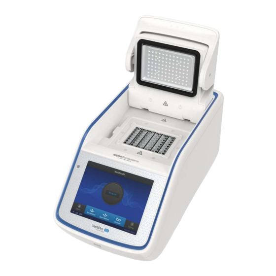
Product information Product description The Applied Biosystems VeritiPro Dx Thermal Cycler is an end-point thermal cycler with a 96-well ™ ™ VeriFlex block (Cat. No. A55826), specifically designed for the amplification of nucleic acids using the ™ Polymerase Chain Reaction (PCR) process. The user interface includes a touchscreen with a graphical display that shows the time, status, and temperature for each run. -
Page 7: Instrument Overview
Chapter 1 Product information Instrument overview Instrument overview The VeritiPro Dx Thermal Cycler allows you to: ™ • Set the instrument secuity mode to safeguard the integrity of validated protocols • Optimize your PCR with the help of the VeriFlex block ™ •... -
Page 8: Chapter 2 Start, Sign On, And Configure The Instrument
Start, sign on, and configure the instrument Installation and instrument verification The instrument is installed by a representative from Thermo Fisher Scientific. The following tasks will be performed during the installation process: • Unpack and install the instrument • Set up an instrument administrator profile •... -
Page 9: Manage User Profiles
Chapter 2 Start, sign on, and configure the instrument Create user profile Manage user profiles All users can manage their profiles to edit personal folder names and change passwords by selecting their (Profile) to enter their My Profile page. Users with Administrator profiles (as indicated by an asterisk after their user name) also have the ability to manage all user accounts by selecting All accounts after entering their My Profile page. -
Page 10: Touchscreen Controls
Chapter 2 Start, sign on, and configure the instrument Touchscreen controls Touchscreen controls Table 1 General touchscreen controls Button Function Returns to the previous screen Go to Home screen Go to Sign in screen Go to Settings screen Advance and return through stages Close the current modal window. Home screen controls Table 2 Home screen controls and indicators Button... -
Page 11: Enter Text
Chapter 2 Start, sign on, and configure the instrument Touchscreen controls Enter text When you select a field that requires the input of text, the alphanumeric text editor, as seen in the following figure, opens. Enter a letter Delete Change letter case Close and save Enter punctuation or other symbols Close without saving... -
Page 12: Set Up The Wired Connection
Chapter 2 Start, sign on, and configure the instrument Set up the wired connection Set up the wired connection IMPORTANT! The network configuration and security settings for your laboratory or facility (such as firewalls, antivirus software, network passwords) are the sole responsibility of your facility administrator, IT, and security personnel. - Page 13 Chapter 2 Start, sign on, and configure the instrument Set up the wired connection 3. In the Settings screen, select Instrument Settings. 4. In the Instrument Settings screen, select Network configuration. 5. In the Network Connection screen, select a field in the Wired panel. 6.
- Page 14 Chapter 2 Start, sign on, and configure the instrument Set up the wired connection b. Select Static IP to enter an IP address manually, then enter the appropriate IP addresses for the instrument, the Subnet Mask, and, optionally, the Default Gateway, the Primary DNS Server, and the Secondary DNS Server using the numeric editor.
-
Page 15: Chapter 3 Methods
Methods Create or edit a method A method is the protocol that controls the parameters for the execution of the PCR run on the instrument. • Select any field on the graphical method profile to edit the parameter (temperature, time, heated cover, number of cycles, and volume). -
Page 16: Create A New Method
Chapter 3 Methods Create or edit a method Create a new method 1. In the Home screen, select Set up run or New method. 2. In the Setup Run screen, select (Open Template). 3. Select a template from the Method Name list. VeritiPro Dx Thermal Cycler User Guide ™... -
Page 17: Edit A Method
Chapter 3 Methods Create or edit a method 4. Select Actions (see “Actions” page 20) or any field on the graphical temperature profile to start editing the parameters. 5. Select Save as, see “Save a method” page 19. 6. (Optional) Select Cancel to exit without making changes, or Start Run to run the method. Edit a method 1. - Page 18 Chapter 3 Methods Create or edit a method 2. In the Setup Run screen, select (Open Method). 3. Select a folder , then select an appropriate template from the Method Name list. Note: At least one method must have previously been set up in order for the list to be populated. 4.
-
Page 19: Save A Method
Chapter 3 Methods Create or edit a method 5. Select Save, see “Save a method” page 19. 6. (Optional) Select Cancel to exit without making changes, or Start Run to run the method. Save a method 1. Once edits to a method are complete, select Save As/Save to save the method. 2. -
Page 20: Actions
Chapter 3 Methods Create or edit a method Actions Select Actions to edit the parameters of a method. Options can be used to: • Add or remove stages and steps • Perform temperature optimization (manage VeriFlex block zones) ™ • Change ramp rates •... - Page 21 Chapter 3 Methods Create or edit a method Note: A maximum of 40 stages can be added in a method. A maximum of 40 steps can be added to a single stage. 3. Select Done when finished, or Cancel to exit the screen without making changes. 4.
- Page 22 Chapter 3 Methods Create or edit a method 4. Select Midpoint to set a midpoint temperature and temperature difference between zones, then enter values in the highlighted text fields. Note: The maximum temperature increment or decrement cannot exceed 10℃. 5. Select 6-zones to set the temperature for each zone of the block, then enter values in the highlighted text fields.
- Page 23 Chapter 3 Methods Create or edit a method Ramp rates 1. Select Ramp Rates to edit the ramp rate of the individual steps. 2. Select a ramp rate to open that ramp rate editor, then edit the ramp rate. Note: The maximum ramp rate is 6.0. 3.
- Page 24 Chapter 3 Methods Create or edit a method 3. Enter the information for setting up AutoDelta. a. Use the '-' and '+' toggle to set the Delta values temperature and time to be either decreased or increased. b. Enter the cycle for the start of AutoDelta in the Start AutoDelta from cycle field. c.
- Page 25 Chapter 3 Methods Create or edit a method Simulation mode 1. Select Simulation Mode to set the simulation mode. Table 3 Simulation modes available on the VeritiPro Dx Thermal Cycler ™ VeritiPro Dx Thermal Cycler ™ • No Simulation (default) • Applied Biosystems Veriti Dx Thermal Cycler ™...
-
Page 26: Manage Methods And Folders
Chapter 3 Methods Create or edit a method Manage methods and folders Management of methods and folders is determined by the user type. Admin users Standard users • Rename or Delete any folder. • Rename or Delete personal folder. • Copy, Rename, or Delete any method in any •... - Page 27 Chapter 3 Methods Create or edit a method 2. In the Setup Run screen, select (Open Method). 3. In the Select Method screen, select New folder. 4. Type a name for the new folder, then select Enter. VeritiPro Dx Thermal Cycler User Guide ™...
- Page 28 Chapter 3 Methods Create or edit a method Manage folders IMPORTANT! Back up your method files to a USB drive frequently, or before sending in your instrument for service. 1. In the instrument Home screen, select Set up run4 (Open method) or (Open method) directly from the bottom of the screen.
- Page 29 Chapter 3 Methods Create or edit a method 3. In the Manage folders screen, select folders from the left column and methods from the right column, then select one of the following options. Select Description Copy To copy a run method from one existing folder to another Rename To rename a particular method/ folder name Delete...
- Page 30 Chapter 3 Methods Create or edit a method 2. Paste the copied method into an existing folder or a new folder. • Select the destination folder for the duplicated method, then select Paste method. • Select New Folder to create a new folder for the duplicated method, then select Paste method.
-
Page 31: Open And Run A Method
Chapter 3 Methods Open and run a method Open and run a method Load samples into the instrument Note: See Appendix E, “How to use the MicroAmp 96-well Tray and Retainer” for instructions on ™ filling, sealing, and loading reaction plates, tube strips, and tubes. Place the sample tray or plate onto the sample block The steps for placing the sample tray on the sample block(s) are the same for: •... - Page 32 Chapter 3 Methods Open and run a method 4. Select Start Run. The cover is heated to the required temperature before the run begins. While the run is in progress, the Home screen is displayed. Select the Status Dial to pause or stop the method.
-
Page 33: Monitoring A Run
Chapter 3 Methods Open and run a method Monitoring a run Monitoring a Run The run status can be viewed from either the Status Dial or the Run Monitoring screen. • View the current run information on the Status Dial from the Home screen. Current block temperature Time remaining since the run started Run status... -
Page 34: View And Export The Run Report
Chapter 3 Methods Open and run a method Stop a run 1. Select the Status Dial in the center of the screen. 2. Select Stop Run4OK. 3. Remove the samples and select Done after the run has finished. View and export the run report 1. -
Page 35: Appendix A Troubleshooting
Troubleshooting Troubleshooting Use the following table to help troubleshoot problems with your Thermal Cycler. Observation Possible cause Recommended action Instrument reports error(s). Hardware malfunction. Run the self verification test (see “Perform self verification test” page 42). Reduction in instrument Temperature sensor out of Call a Thermo Fisher Scientific service performance due to incorrect calibration. - Page 36 Appendix A Troubleshooting Troubleshooting Observation Possible cause Recommended action Power failure during a run. Power failure during a run. If a power failure occurs during a run, the instrument attempts to continue the run when the power returns. The run begins at the first step of the stage where the power failed.
-
Page 37: Return An Instrument For Service
Appendix A Troubleshooting Return an instrument for service Return an instrument for service Before returning an instrument for service, back up the run methods and instrument settings, as described in “Manage folders” on page 28 and “Recommended instrument settings” page 44. This practice ensures that you can restore the run methods and other settings in the event that the service center replaces a component that restores the default factory settings, or sends you a replacement instrument. -
Page 38: Appendix B Maintenance
Maintenance IMPORTANT! This chapter contains user maintenance procedures for the instrument. Procedures other than those described in this document must be performed by a qualified Thermo Fisher Scientific service representative. Clean the instrument WARNING! Always wear protective glasses and gloves when servicing the instrument. Also, make sure you disconnect the instrument from AC line power before you begin any service procedure. -
Page 39: Clean The Sample Wells
Appendix B Maintenance Clean the instrument Clean the sample wells If you use any cleaning or decontamination method, except those recommended in the manual, you risk damaging the equipment. Clean the sample wells once a month or as needed. WARNING! During instrument operation, the temperature of the heated cover can be as high as 110°C, and the temperature of the sample block(s) can be as high as 100°C. -
Page 40: Decontaminate The Heated Cover
Appendix B Maintenance Clean the instrument 3. Soak a cotton swab or piece of clean cloth with isopropanol and gently wipe the heated platen. WARNING! CHEMICAL HAZARD. Isopropanol is a flammable liquid and vapor. Exposure may cause eye, skin, and upper respiratory tract irritation. Prolonged or repeated contact may dry skin and cause irritation. -
Page 41: Replace The Fuses
Appendix B Maintenance Replace the fuses Replace the fuses Required materials • Two UL listed fuses, rated 10 A, type T (time-lag), 5 × 20 mm, 250 VAC • Small flat-tip screwdriver Procedure DANGER! ELECTRICAL SHOCK HAZARD. Severe electrical shock, which could cause physical injury or death, can result from working on an instrument when the high voltage power supply is operating. -
Page 42: Request Maintenance Support
Appendix B Maintenance Request maintenance support Request maintenance support IMPORTANT! The instrument requires annual maintenance and qualification to be performed by a certified Thermo Fisher Scientific representative (see page 49 to set service reminders). Contact your Thermo Fisher Scientific representative to schedule the required service. Contact your Thermo Fisher Scientific service representative if it is necessary to perform any of the following functions. -
Page 43: Restore Factory Settings (Administrator Profile Only)
Appendix B Maintenance Restore factory settings (Administrator profile only) Restore factory settings (Administrator profile only) On the Restore Factory Settings screen, select Restore to remove all data and customized settings and revert to the factory settings. All data and settings are erased after factory settings are restored. The message, "Your instrument has been restored."... -
Page 44: Appendix C Recommended Instrument Settings
Recommended instrument settings About Instrument Select Settings4About instrument to find out more information about the instrument (e.g., firmware version and instrument statistics). • Select EULA to view the End User License Agreement, or download it to a USB drive. • Check updates is only enabled when a Thermo Fisher Scientific representative is logged in to the service account (see page 42 for details on software updates). -
Page 45: Instrument Settings
Appendix C Recommended instrument settings Recommended instrument settings Instrument Settings Select Instrument settings to set the following instrument parameters. • Instrument name Select the Instrument name field to activate the text editor. Enter up to 25 alphanumeric characters to identify the instrument. Note: The instrument name cannot have spaces. - Page 46 Appendix C Recommended instrument settings Recommended instrument settings • Heated cover temperature Use the Off and On toggle to disable or enable activation of the heated cover in idle mode. In the 'On' mode, select the Edit Temperature field to activate the numeric editor to set the cover temperature.
- Page 47 Appendix C Recommended instrument settings Recommended instrument settings • Printer configuration Select the Remote Printer IP Address field to activate the numeric editor, then enter the IP address of the printer to be connected to the instrument. • Network configuration Displays the network connection status, IP address, and MAC address of the instrument. For details on setting up a wired connection, see “Set up the wired connection”...
- Page 48 Appendix C Recommended instrument settings Recommended instrument settings • Sleep mode Use the Off and On toggle to disable or enable sleep mode. In the 'On' mode, select the Edit Time field to activate the numeric editor to set the time after which the instrument will go from idle mode to standby mode.
-
Page 49: Maintenance And Services
Appendix C Recommended instrument settings Maintenance and services • Language – Select Settings4Instrument settings4Language, then select a language from the menu. Maintenance and services Select Maintenance & Services to set the following instrument parameters. • Software update is only enabled when a Thermo Fisher Scientific representative is logged in to the service account (see page 42 for details on software updates). -
Page 50: Run History
Appendix C Recommended instrument settings Run history • Select Backup/Restore (Administrator profile only) is useful in event of a hardware failure. See page 9 for details on using the administrator profile. – Select Backup Instrument to back up the instrument settings, user accounts, and methods on the instrument to a USB memory device. -
Page 51: Usb Shortcuts
Appendix C Recommended instrument settings USB shortcuts Note: If you are signed in with the Administrator profile, you can use the Manage function to perform the following functions. · Delete a run report · Select all run reports · Export a run report USB shortcuts Select USB Shortcuts to manage the shortcuts available when a USB memory device is inserted into the instrument. - Page 52 Appendix C Recommended instrument settings USB shortcuts Note: Backup/Restore is only available when signed in as administrator. When a USB memory device is plugged into the USB port, a pop-up dialog box with the pre-selected options is displayed. VeritiPro Dx Thermal Cycler User Guide ™...
-
Page 53: Appendix D Instrument Specification And Layout
Instrument specification and layout Site requirements The instrument is for indoor use. Ensure that the installation site meets the following requirements: • Meets the spatial and weight requirements (see “Specifications”) • Meets environmental requirements (see “Environmental requirements”) • Is within 1 m (3 ft.) of an AC power source receptacle •... -
Page 54: Altitude
Appendix D Instrument specification and layout Specifications Altitude The safety of instrument use was tested for altitudes up to 6000 ft. Specifications Technical specifications Feature Specification Maximum block ramp rate 6.0°C/sec Temperature accuracy ±0.25°C (35–99.9°C) Temperature range for protocol run 0.0–100.0°C Temperature non-uniformity ≤0.50 •... -
Page 55: Physical Dimensions
Appendix D Instrument specification and layout Power and communication port symbols (continued) Feature Specification Power consumption Average during thermal cycling: 260 W During sleep/ standby: 25 W Reaction volume of 1 µL. 30 seconds after clock starts. Temperature accuracy ±0.50 and Temperature non-uniformity ≤0.75. Physical dimensions Parameter Instrument footprint... -
Page 56: Location Of Power Point And Ports On The Instrument
Appendix D Instrument specification and layout Location of power point and ports on the instrument Location of power point and ports on the instrument The following graphic displays the location of the power cable port, and other ports on the instrument. Ethernet port USB port Fuse compartment door Main power switch... - Page 57 How to use the MicroAmp 96-well ™ Tray and Retainer IMPORTANT! Use the MicroAmp 96-well Tray and Retainer to prevent crushing of tubes in the ™ thermal cycler. When a small number of tubes (1–2 tube strips or ≤8–16 tubes are placed in the sample block without support, they can be crushed or deformed when the lid of the thermal cycler is closed over the block.
-
Page 58: Appendix E How To Use The Microamp 96-Well Tray And Retainer
Appendix E How to use the MicroAmp 96-well Tray and Retainer ™ Prepare samples using MicroAmp tubes/tube strips with separate cap strips ™ Prepare samples using MicroAmp tubes/tube strips with ™ separate cap strips The following procedure describes how to properly load and seal MicroAmp tube strips using cap strips and the MicroAmp 96-well tray/retainer set. - Page 59 Appendix E How to use the MicroAmp 96-well Tray and Retainer ™ Prepare samples using MicroAmp tubes/tube strips with separate cap strips ™ 7. Remove the blue tray/retainer assembly containing the sealed tube strips from the 96-well base and place the assembly into the instrument. MicroAmp 8-Cap strip ™...
-
Page 60: Prepare Samples Using Microamp ™ Tube Strips With Attached Caps
Appendix E How to use the MicroAmp 96-well Tray and Retainer ™ Prepare samples using MicroAmp tube strips with attached caps ™ Prepare samples using MicroAmp tube strips with ™ attached caps The following procedure describes how to properly load and seal MicroAmp tube strips with attached caps using the MicroAmp 96-well tray/retainer set. - Page 61 Appendix E How to use the MicroAmp 96-well Tray and Retainer ™ Prepare samples using MicroAmp tube strips with attached caps ™ 6. Remove the blue tray containing the sealed tube strips from the 96-well base and place the tray and sealed tube strips into the instrument. MicroAmp 8-Tube Strip with Attached Caps (0.2-mL) ™...
-
Page 62: Seal Tube Strips With Cap Strips
Appendix E How to use the MicroAmp 96-well Tray and Retainer ™ Seal tube strips with cap strips Seal tube strips with cap strips IMPORTANT! Apply significant downward pressure on the sealing tool in all steps to form a complete seal on top of the tubes. 1. -
Page 63: Prepare Samples Using Microamp ™ Reaction Tubes
Appendix E How to use the MicroAmp 96-well Tray and Retainer ™ Prepare samples using MicroAmp Reaction Tubes ™ Prepare samples using MicroAmp Reaction Tubes ™ The following procedure describes how to properly load and seal MicroAmp individual tubes with ™ attached caps and the MicroAmp 96-well tray for VeriFlex systems. -
Page 64: Appendix F Ordering Information
Ordering information Instrument part numbers Contact your regional sales office to order kits, accessories, consumables, and spare parts for the VeritiPro Dx 96-well Thermal Cycler (Cat. No. A55826). ™ Consumables IMPORTANT! The customer is responsible for validation of all consumables before use, and for compliance with regulatory requirements that pertain to the procedures and uses with the instrument. - Page 65 Appendix F Ordering information Consumables (continued) Product Cat. No. Accessories MicroAmp Clear Adhesive Film 4306311 ™ Optical Adhesive Covers GPLE A49767 VeritiPro Dx Thermal Cycler User Guide ™...
-
Page 66: Appendix G Safety
Safety WARNING! GENERAL SAFETY. Using this product in a manner not specified in the user documentation may result in personal injury or damage to the instrument or device. Ensure that anyone using this product has received instructions in general safety practices for laboratories and the safety information provided in this document. -
Page 67: Safety Symbols On This Instrument
Appendix G Safety Safety symbols on this instrument (continued) Symbol English Français Do not dispose of this product in unsorted Ne pas éliminer ce produit avec les déchets usuels municipal waste non soumis au tri sélectif. CAUTION! To minimize negative MISE EN GARDE ! Pour minimiser les environmental impact from conséquences négatives sur l’environne... -
Page 68: Safety Information For Instruments Not Manufactured By Thermo Fisher Scientific
Appendix G Safety Safety information for instruments not manufactured by Thermo Fisher Scientific Figure 3 Location of the caution symbols on the sample block Safety information for instruments not manufactured by Thermo Fisher Scientific Some of the accessories provided as part of the instrument system are not designed or built by Thermo Fisher Scientific. -
Page 69: Physical Injury
Appendix G Safety Safety and electromagnetic compatibility (EMC) standards Physical injury CAUTION! Moving Parts. Moving parts can crush, pinch and cut. Keep hands clear of moving parts while operating the instrument. Disconnect power before servicing. WARNING! Sharp Edges. The edges of this container are sharp. Electrical safety WARNING! Ensure appropriate electrical supply. -
Page 70: Safety
Appendix G Safety Safety and electromagnetic compatibility (EMC) standards Safety Reference Description EU Directive 2014/35/EU European Union “Low Voltage Directive” IEC 61010-1 Safety requirements for electrical equipment for measurement, control, and laboratory use – Part 1: General requirements EN 61010-1 UL 61010-1 CAN/CSA C22.2 No. -
Page 71: Class A Notice
Appendix G Safety Safety and electromagnetic compatibility (EMC) standards (continued) Reference Description FCC Part 15 Subpart B (47 U.S. Standard Radio Frequency Devices CFR) IEC 61326-2-6 Electrical equipment for measurement, control and laboratory use – EMC requirements: EN 61326-2-6 Particular requirements – In vitro diagnostic (IVD) medical equipment WARNING! Use of this equipment adjacent to or stacked with other equipment should be avoided because it could result in improper operation. -
Page 72: Chemical Safety
Appendix G Safety Chemical safety Chemical safety WARNING! GENERAL CHEMICAL HANDLING. To minimize hazards, ensure laboratory personnel read and practice the general safety guidelines for chemical usage, storage, and waste provided below. Consult the relevant SDS for specific precautions and instructions: · Read and understand the Safety Data Sheets (SDSs) provided by the chemical manufacturer before you store, handle, or work with any chemicals or hazardous materials. -
Page 73: Biological Hazard Safety
Appendix G Safety Biological hazard safety Biological hazard safety WARNING! BIOHAZARD. Biological samples such as tissues, body fluids, infectious agents, and blood of humans and other animals have the potential to transmit infectious diseases. Conduct all work in properly equipped facilities with the appropriate safety equipment (for example, physical containment devices). -
Page 74: Appendix H Documentation And Support
Documentation and support Customer and technical support Visit thermofisher.com/support for the latest service and support information. • Worldwide contact telephone numbers • Product support information – Product FAQs – Software, patches, and updates – Training for many applications and instruments •... - Page 76 VeritiPro Dx_UG_MAN0028460-v7-GUID-D71DACE9-10F5-40DF-A455-57C96EA06D55-2023/08/18 20:49:46 21:06:26.719+01:00 thermofisher.com/support | thermofisher.com/askaquestion thermofisher.com 18 August 2023...
Need help?
Do you have a question about the VeritiPro Dx Thermal Cycle and is the answer not in the manual?
Questions and answers