
Related Manuals for Thermo Scientific Varioskan ALF


Summary of Contents for Thermo Scientific Varioskan ALF
- Page 1 Varioskan ALF Multimode Microplate Reader ™ USER GUIDE Catalog Numbers VA000010C Publication Number MAN0030013 Revision B00 Laboratory Use Non-Regulated.
- Page 2 Thermo Fisher Scientific (Guangzhou) Biotechnology Company, Ltd. | Block B3 1-5F, Block B4 1-4F | No. 77 Kang Zhao 2nd Road | Huangpu District, Guangzhou, China Revision history: MAN0030013 B00 (English) Revision Date Description 19 April 2024 Update of usage statement to LUN. 5 February 2024 New manual for the Varioskan ALF Multimode Microplate Reader.
-
Page 3: Table Of Contents
Contents ■ CHAPTER 1 Product information ..........5 Product description . - Page 4 Contents ■ APPENDIX B Safety ............. . . 30 Symbols on the instrument .
-
Page 5: Chapter 1 Product Information
• Most luminescence measurements do not require wavelength selection. But if required, filters can be used. The instrument supports all common 6-well, 12-well, 24-well, 48-well, 96-well, and 384-well microplates with or without lids or seals, as well as low-volume microplates. Additionally Thermo Scientific µDrop ™... -
Page 6: Instrument Overview
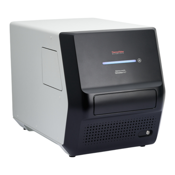
Chapter 1 Product information Instrument overview Instrument overview Figure 1 Front view of the Varioskan ALF Multimode Microplate Reader ™ Power switch LED bar indicator (see table for explanations) Measurement chamber door Front cover Plate In/Out button Filter wheel chamber door LED bar indicator Instrument state Blue light changing brightness slowly Power on... - Page 7 Chapter 1 Product information Instrument overview Figure 2 Rear view of the Varioskan ALF Multimode Microplate Reader ™ USB-B connector Cooling fan outlets Mains power supply connector Filter wheel chamber door Figure 3 Internal view of the Varioskan ALF Multimode Microplate Reader ™ Excitation filter wheel door Excitation filter wheel Emission filter wheel door Emission filter wheel...
-
Page 8: Principle Of Operation
Chapter 1 Product information Principle of operation Principle of operation The instrument is equipped with the following two detection modules: • Photometry module used for absorbance and turbidity detection • Fluorometry & Luminometry (FL) module, used for fluorescence intensity (FI) and luminescence detection Photometry module FL module... - Page 9 Chapter 1 Product information Principle of operation Luminometric measurements shared the emission path of fluorometry. To minimize the crosstalk interference, an automatic shield is used. However, the automatic crosstalk shield will not be used if the height of the plate is above 15.5 mm in luminometric measurements. Varioskan ALF Multimode Microplate Reader User Guide ™...
-
Page 10: Chapter 2 Set Up The Instrument
Set up the instrument The following installation steps must be performed before the instrument can be operated. 1. Remove the transport lock. 2. Connect the mains supply cable. 3. Connect the instrument to a computer. 4. Install the SkanIt Software for Microplate Readers to the computer connected to the instrument. ™... - Page 11 Chapter 2 Set up the instrument Remove the transport lock 2. Unscrew the transport lock bar by turning it counterclockwise. 3. Pull the transport lock until the plate carrier is fully out of the measurement chamber. 4. Unfasten two fixing screws and remove the transport lock from the plate carrier. 5.
-
Page 12: Connect The Mains Supply Cable
Chapter 2 Set up the instrument Connect the mains supply cable 6. Attach the transport lock on the back of the instrument with the fixing screw and the locking piece that is on the back of the instrument. Connect the mains supply cable 1. -
Page 13: Perform An Operational Check
Chapter 2 Set up the instrument Perform an operational check Perform an operational check When the instrument is switched on, the instrument performs self-diagnostic tests and the LED bar indicator displays a blue light changing brightness slowly. When the plate carrier is extended out from the measurement chamber, and the LED bar indicator displays a steady blue light, the instrument is ready for use. -
Page 14: Chapter 3 Methods
Methods Instrument operation This chapter describes the instrument preparation steps you can take before you start a measurement. After you have installed the instrument, switch it on and start the SkanIt software. The software finds ™ the instrument automatically. If you have not installed the software, see “Install the SkanIt software”... -
Page 15: Switch Off The Instrument
Chapter 3 Methods Instrument operation If anything fails in the initialization tests or adjustments, the LED bar turns to a blinking amber . Turn the power switch off, then on. If this does not help, contact Technical Support. CAUTION! Do not switch the power off during startup or self-diagnostics. Switch off the instrument Switch the instrument off after daily operation. -
Page 16: Instrument Temperature
Chapter 3 Methods Instrument operation Instrument temperature Instrument temperature is set using the SkanIt software (up to a maxiumum of 45°C). ™ The software shows both the current and target temperatures until the target temperature is reached. When the incubator is on, the LED bar display flash very slowly. This state can be interrupted by other LED bar indicator states. - Page 17 Chapter 3 Methods Instrument operation Identify instrument in SkanIt software ™ 1. Turn on the instrument and open the SkanIt software. ™ The software automatically identifies any connected instruments. 2. Select Menu to open the Application menu, then select Settings to open the Edit application settings window.
- Page 18 Chapter 3 Methods Instrument operation 3. Select Instruments to open the Edit instrument parameters window. Currently connected instruments are shown in the Instruments list. Instruments Instruments list Settings 4. Select Settings to open the Edit instrument parameters window. Varioskan ALF Multimode Microplate Reader User Guide ™...
- Page 19 Chapter 3 Methods Instrument operation 5. Select the Filter definition tab of Edit instrument parameters window to add accessory excitation (see page 19 and emission (see page 22) filters. Add excitation filter 1. Select Add in the Filter definition tab to add an excitation filter. Varioskan ALF Multimode Microplate Reader User Guide ™...
- Page 20 Chapter 3 Methods Instrument operation 2. Input Filter ID (Cat. No. of filter), Name, Central wavelength, and FWHM (full width at half maximum) in the Define filter dialog box. 3. Select Next to view the Position filter dialog box. The instrument will rotate the filter wheel so it is ready for filter installation. 4.
- Page 21 Chapter 3 Methods Instrument operation IMPORTANT! Do not touch the surfaces of the filter with bare hands. Excitation filter wheel door Arrow indicating direction of light propagation Accessory filter 5. Close the excitation wheel door, then close the filter wheel chamber door. Select Next to view the Finish dialog box and confirm the filter parameters.
- Page 22 Chapter 3 Methods Instrument operation 6. Select Finish. IMPORTANT! Do not forget to close the excitation filter wheel door and the filter wheel chamber door after inserting accessory filters. The new filter is displayed in the Excitation filters list. Add emission filter 1.
- Page 23 Chapter 3 Methods Instrument operation 2. Input Filter ID (Cat. No. of filter), Name, Central wavelength, and FWHM (full width at half maximum) in the Define filter dialog box. 3. Select Next to view the Position filter dialog box. The instrument will rotate the filter wheel so it is ready for filter installation. 4.
- Page 24 Chapter 3 Methods Instrument operation IMPORTANT! Do not touch the surfaces of the filters with bare hands. Emission filter wheel door Arrow indicating direction of light propagation Accessory filter 5. Close the emission wheel door, then close the filter wheel chamber door. Select Next to view the Finish dialog box and confirm the filter parameters.
- Page 25 Chapter 3 Methods Instrument operation 6. Select Finish. IMPORTANT! Do not forget to close the emission filter wheel door and the filter wheel chamber door after inserting accessory filters. The new filter is displayed in the Emission filters list. Add fluorometric filter pairs 1.
-
Page 26: Using The Skanit ™ Software
Chapter 3 Methods Instrument operation 2. Input a name for the new filter pair. Select an excitation filter and an emission filter to form a fluorometric filter pair, then select OK. The new fluorometric filter pair is displayed in the Fluorometric filter pairs list. Using the SkanIt software ™... -
Page 27: Chapter 4 Maintenance
Maintenance Instrument maintenance Clean the instrument Clean the instrument after each use. 1. Switch the instrument off with the plate carrier extended out of the measurement chamber. 2. Unplug the instrument. 3. Wipe the surface of the plate carrier with a soft cloth or tissue paper moistened with distilled water, mild detergent (SDS, sodium dodecyl sulfate) or a soap solution. -
Page 28: Maintenance Checklist
— — ✓ Perform verification with Themo Scientific Multifunctional Verification — — — ✓ plate or Thermo Scientific Lumiwell plate. Decontaminate the instrument when — — — ✓ relocating the instrument or sending it for service. Service the instrument regularly. -
Page 29: Appendix A Specifications
Specifications Instrument specifications Parameter Description Operating conditions +10°C to +40°C; Maximum relative humidity 80% for temperatures up to 31°C, decreasing linearly to 50% relative humidity at 40°C Indoor use only Mains power supply 100–240 Vac, 50/60 Hz, nominal Power consumption MaxImum: 305 W;... -
Page 30: Appendix B Safety
Safety WARNING! GENERAL SAFETY. Using this product in a manner not specified in the user documentation may result in personal injury or damage to the instrument or device. Ensure that anyone using this product has received instructions in general safety practices for laboratories and the safety information provided in this document. - Page 31 Appendix B Safety Symbols on the instrument (continued) Symbol English The UKCA mark symbolizes that the product conforms to all applicable provisions in Great Briitain (England, Wales, and Scotland) for which this marking is required. Operation of the instrument is subject to the conditions described in this manual. The protection provided by the device may be impaired if the instrument is used in a manner not specified by the manufacturer.
-
Page 32: Instrument Safety
Appendix B Safety Instrument safety Instrument safety General instrument safety • The instrument is for laboratory research use only. • Observe proper laboratory safety precautions; wear protective clothing and follow approved laboratory safety procedures. • Follow Good Laboratory Practice (GLP) to guarantee reliable analyses. •... -
Page 33: Electrical Safety
Appendix B Safety Safety and electromagnetic compatibility (EMC) standards Electrical safety WARNING! Ensure appropriate electrical supply. For safe operation of the instrument: · Plug the system into a properly grounded receptacle with adequate current capacity. · Ensure the electrical supply is of suitable voltage. ·... -
Page 34: Safety
Appendix B Safety Safety and electromagnetic compatibility (EMC) standards Safety Reference Description CE-LVD (2014/35/EU) European Union “Low Voltage Directive” IEC 61010-1 Safety requirements for electrical equipment for measurement, control, and laboratory use – Part 1: General requirements GB 4793.1 EN 61010-1 IEC 61010-2-010 Safety requirements for electrical equipment for measurement, control and laboratory use –... -
Page 35: Chemical Safety
Appendix B Safety Chemical safety Chemical safety WARNING! GENERAL CHEMICAL HANDLING. To minimize hazards, ensure laboratory personnel read and practice the general safety guidelines for chemical usage, storage, and waste provided below. Consult the relevant SDS for specific precautions and instructions: · Read and understand the Safety Data Sheets (SDSs) provided by the chemical manufacturer before you store, handle, or work with any chemicals or hazardous materials. -
Page 36: Biological Hazard Safety
Appendix B Safety Biological hazard safety Biological hazard safety WARNING! Potential Biohazard. Depending on the samples used on this instrument, the surface may be considered a biohazard. Use appropriate decontamination methods when working with biohazards. WARNING! BIOHAZARD. Biological samples such as tissues, body fluids, infectious agents, and blood of humans and other animals have the potential to transmit infectious diseases. -
Page 37: Appendix C Documentation And Support
Documentation and support Customer and technical support Visit thermofisher.com/support for the latest service and support information. • Worldwide contact telephone numbers • Product support information – Product FAQs – Software, patches, and updates – Training for many applications and instruments •... - Page 38 Varioskan ALF Microplate Reader_UG_MAN0030013-v2-GUID- A43000E8-29D2-4B6D-92B6-5292976F8A92-2024/03/12 19:36:31 en 19:39:12.127+01:00 thermofisher.com/support | thermofisher.com/askaquestion thermofisher.com 19 April 2024...
Need help?
Do you have a question about the Varioskan ALF and is the answer not in the manual?
Questions and answers