ZyXEL Communications IES-1000 User Manual
Integrated ethernet switch
Hide thumbs
Also See for IES-1000:
- User manual (139 pages) ,
- Hardware installation manual (51 pages) ,
- Specifications (4 pages)
Table of Contents
Advertisement
Advertisement
Table of Contents
Troubleshooting

Subscribe to Our Youtube Channel
Related Manuals for ZyXEL Communications IES-1000


Summary of Contents for ZyXEL Communications IES-1000
- Page 1 IES-1000 Integrated Ethernet Switch Version 2.05 11/2005 User’s Guide...
-
Page 2: Copyright
ZyXEL Communications Corporation. Published by ZyXEL Communications Corporation. All rights reserved. Disclaimer ZyXEL does not assume any liability arising out of the application or use of any products, or software described herein. -
Page 3: Interference Statements And Warnings
Select your product from the drop-down list box on the ZyXEL home page to go to that product's page. Step 2. Select the certification you wish to view from this page. Step 3. Interference Statements and Warnings IES-1000 User’s Guide... -
Page 4: Zyxel Limited Warranty
IES-1000 User’s Guide ZyXEL Limited Warranty ZyXEL warrants to the original end user (purchaser) that this product is free from any defects in materials or workmanship for a period of up to two years from the date of purchase. During the warranty period, and upon proof... -
Page 5: Customer Support
ZyXEL Hungary 48, Zoldlomb Str. H-1025, Budapest Hungary ZyXEL Kazakhstan43, Dostyk ave.,Office Dostyk Business Centre 050010, Almaty Republic of Kazakhstan ZyXEL Communications Inc. 1130 N. Miller St. Anaheim CA 92806-2001 U.S.A. ZyXEL Communications A/S Nils Hansens vei 13 0667 Oslo Norway ZyXEL Communications ul.Emilli Plater... - Page 6 08707 555779 (UK only) +44-1344 303034 ftp.zyxel.co.uk ZyXEL Communications Alejandro Villegas 33 1º, 28043 Madrid Spain ZyXEL Communications A/S Sjöporten 4, 41764 Göteborg Sweden ZyXEL Ukraine13, Pimonenko Str. Kiev, 04050 Ukraine ZyXEL Communications UK Ltd.,11 The Courtyard, Eastern Road, Bracknell,...
-
Page 7: Table Of Contents
Chapter 4 Hardware Installation... 4-1 Environment... 4-1 Freestanding IES-1000 Installation Requirements... 4-1 Rack-mounted IES-1000 Installation Requirements ... 4-1 Mounting the IES-1000 on a Rack ... 4-1 Chapter 5 Removing and Installing Network Modules ... 5-1 Table of Contents IES-1000 User’s Guide... - Page 8 SHDSL Port Connections...6-2 ADSL Port Connections ...6-5 AC Power Model Power Connection ...6-12 DC Power Model Power Connections...6-13 Chapter 7 Turning On the IES-1000... 7-1 Introduction ...7-1 Network Module Front Panel LEDs...7-1 Chapter 8 Hardware Troubleshooting ... 8-1 System Startup...8-1 The ALM LED Is On ...8-1...
- Page 9 DSL Port Channel Setup Screen ... 13-2 13.3 ATM QoS... 13-3 13.4 Traffic Shaping... 13-3 Advanced Applications and Management ...IV Chapter 14 Static Route ... 14-1 14.1 Static Route Overview ... 14-1 14.2 Static Route Setup Screen ... 14-1 Table of Contents IES-1000 User’s Guide...
- Page 10 IES-1000 User’s Guide Chapter 15 VLAN... 15-1 15.1 VLAN Overview ...15-1 15.2 Tagged VLANs (IEEE 802.1Q) ...15-1 15.3 Forwarding Tagged and Untagged Frames ...15-2 15.4 Filtering Databases ...15-2 15.5 Automatic VLAN Registration...15-3 15.6 GARP ...15-3 15.7 VLAN Setup...15-4 15.8 Static VLAN Setup Screen...15-4 Chapter 16 SNMP...
- Page 11 Virtual Channel Management... 26-1 26.1 About Virtual Channels... 26-1 26.2 Virtual Channel Profile Commands ... 26-1 26.3 PVC Channels ... 26-4 Chapter 27 10/100M Fast Ethernet Port Commands... 27-1 27.1 10/100M Fast Ethernet Overview ... 27-1 Table of Contents IES-1000 User’s Guide...
- Page 12 IES-1000 User’s Guide 27.2 Ethernet Commands ...27-1 Chapter 28 Bridge Commands ... 28-1 28.1 Bridge Commands Overview ...28-1 28.2 Bridge Port Numbers...28-1 28.3 Basic Commands ...28-1 28.4 MAC Filter Commands ...28-2 28.5 Filter Commands ...28-3 28.6 Port Filter Commands (Port-Based VLAN) ...28-5 28.7...
- Page 13 Ethernet Port... 37-5 Appendices and Index...VI Appendix A Safety Warnings ... A Appendix B Removing and Installing a Fuse ...C Appendix C Pin Assignments ... E Appendix D Hardware Specifications ...G Index... I Table of Contents IES-1000 User’s Guide xiii...
-
Page 14: List Of Figures
Figure 6-11 Installation Scenario C ... 6-11 Figure 6-12 Stacking Multiple IES-1000 Units... 6-12 Figure 6-13 Connecting the Power Cord to the IES-1000 and a Power Source... 6-13 Figure 6-14 Connecting IES-1000 Power... 6-14 Figure 7-1 Location of the IES-1000 Fans ... 7-1 Figure 7-2 SAM1008 Front Panel LEDs... - Page 15 IES-1000 User’s Guide Figure 9-2 Home Screen ... 9-2 Figure 9-3 Bridge Setup Example ... 9-4 Figure 9-4 Bridge Packet Type Filter Setup Example ... 9-5 Figure 10-1 General Setup... 10-1 Figure 10-2 Bridge Setup ... 10-3 Figure 10-3 Bridge Packet Type Filter Setup ... 10-4 Figure 10-4 Default Port Filter Settings...
- Page 16 IES-1000 User’s Guide Figure 12-3 G.SHDSL Profile Setup ... 12-6 Figure 12-4 G.SHDSL Add Profile ... 12-7 Figure 12-5 G.SHDSL Port Setup... 12-8 Figure 12-6 Add G.SHDSL N-wire Group ... 12-9 Figure 12-7 Add G.SHDSL Port Bonding... 12-11 Figure 13-1 DSL Port Channel Setup... 13-2 Figure 13-2 PCR, SCR, MCR and MBS in Traffic Shaping...
- Page 17 IES-1000 User’s Guide Figure 20-3 Reboot System Confirmation... 20-6 Figure 20-4 Logout ... 20-7 Figure 24-1 Linedata Command Example ... 24-4 Figure 24-2 Lineinfo Command Example... 24-4 Figure 24-3 Lineperf Command Example ... 24-6 Figure 24-4 Linerate Command Example ... 24-8 Figure 24-5 List Profiles Command Example...
- Page 18 IES-1000 User’s Guide Figure 33-1 Setting IP Address and Default Gateway... 33-2 Figure 36-1 BOOTP/TFTP Server ... 36-3 Figure 36-2 Input MAC ... 36-3 Figure 36-3 Database Edit Dialog ... 36-4 Figure 36-4 Enable BOOTP/TFTP ... 36-4 Figure 36-5 Enter Debug Mode ... 36-4...
- Page 19 Table 3-1 Front Panel Ports of the SAM1008 Network Module ... 3-2 Table 3-2 Front Panel Ports of the AAM1008 Network Module... 3-2 Table 3-3 Front Panel Ports of the IES-1000 ... 3-2 Table 7-1 Network Module LED Descriptions... 7-2 Table 8-1 SYS LED Troubleshooting...
- Page 20 IES-1000 User’s Guide Table 10-18 Bridge Fast Mode VLAN ID Setup... 10-21 Table 10-19 IP Setup ... 10-22 Table 11-1 Maximum Transfer Rates of the ADSL Ports ... 11-1 Table 11-2 ADSL Port Setup ... 11-4 Table 11-3 ADSL Profile Setup ... 11-5 Table 11-4 ADSL Add Profile...
- Page 21 Table 24-1 Lineinfo Command ... 24-5 Table 24-2 Line Performance Counters ... 24-7 Table 28-1 Physical Ports, Port Numbers and IES-1000 Default PVID Tags in Fast Mode... 28-8 Table 37-1 Troubleshooting the DSL LED(s)... 37-1 Table 37-2 Troubleshooting Data Transmission ... 37-1 Table 37-3 Troubleshooting a Non-Constant DSL LED...
-
Page 22: Preface
See the AAM-1212 User’s Guide for information on the AAM-1212-51/53 network modules. IES-1000 Network Module Models and Firmware Releases The IES-1000 supports the following modules. The firmware version contains a model code. In firmware version V2.05(DN.1) for example; “DN” is the model code. - Page 23 Help us help you. E-mail all User’s Guide-related comments, questions or suggestions for improvement to techwriters@zyxel.com.tw or send regular mail to The Technical Writing Team, ZyXEL Communications Corp., 6 Innovation Road II, Science-Based Industrial Park, Hsinchu, 300, Taiwan. Thank you.
-
Page 24: Overview And Installation
Overview and Installation Part I: Overview and Installation This part introduces the general features, default settings, hardware and installation of the IES- 1000 Integrated Ethernet Switch. -
Page 26: Getting To Know The Ies-1000
AAM-1212 User’s Guide for information on the AAM-1212-51/53 network modules. Features Two-Slot Chassis The IES-1000 has two slots that accept multiplexer network modules. The chassis design gives you the flexibility to initially install a single module and then add another as demand increases. Multiplexer Network Modules Up to two hot-swappable multiplexing network modules may be installed in each IES-1000 chassis. -
Page 27: Fast Mode
IEEE 802.1Q Tagged VLAN Your IES-1000 uses the IEEE 802.1Q Tagged VLAN (Virtual Local Area Network), which allows your device to deliver tagged/untagged frames to and from its ports. The IES-1000 supports up to 400 VLANs and up to 4094 VLAN IDs. -
Page 28: Igmp Snooping
The IES-1000 can relay client TCP/IP configuration requests to a DHCP server and the server’s responses back to the clients. The IES-1000 also has the relay agent information option (also known as option 82) feature to add information to client TCP/IP configuration requests that it relays to a DHCP server. -
Page 29: Applications
IES-1000 User’s Guide Overheating Detection, Warning and Safegaurd An ALM LED turns on when the IES-1000’s internal temperature is too high and turns off when the temperature has returned to a normal level. Internal fans cool the unit. Compact Design for Limited Space The IES-1000 occupies only 1 U of standard Telco rack space. -
Page 30: Figure 1-1 Mtu Application
IES-1000 User’s Guide Figure 1-1 MTU Application Getting to Know the IES-1000... -
Page 31: Figure 1-2 Central Office Or Isp Application
1.2.2 Central Office or ISP Application The IES-1000 provides DSL service over telephone wires to subscribers. The following figure shows the IES- 1000 set up in an Internet Service Provider (ISP) building or telephone company central office. Figure 1-2 Central Office or ISP Application... -
Page 32: Factory Default Settings
Password: 1234 (default) G.SHDSL Ports (SAM1008) • Encapsulation: RFC 1483 • Multiplexing: LLC-based • VPI: 0 • VCI: 33 Factory Default Settings Factory Default Settings This section describes the factory default settings of the IES-1000. IES-1000 User’s Guide Chapter 2... -
Page 33: Adsl Ports (Aam1008)
Operational Mode: auto • Profile: DEFVAL Maximum Upstream Rate: 512 Kbps Maximum Downstream Rate: 2048 Kbps Ethernet Port The factory default settings for the Ethernet port of the IES-1000 are: • Auto-negotiation: ON • Speed used with auto-negotiation OFF: 100Mbps •... - Page 34 IES-1000 User’s Guide Factory Default Settings...
-
Page 36: Chapter 3 Hardware Overview
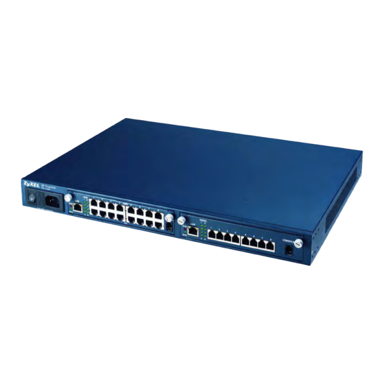
No flow control AC Power Front Panel The following figure shows the front panel of the AC power version of the IES-1000 with a SAM1008 network module installed on the left and an AAM1008 network module on the right. DC Power Front Panel The following figure shows the front panel of the DC power version of the IES-1000 with a SAM1008 network module installed on the left and an AAM1008 network module on the right. -
Page 37: Table 3-1 Front Panel Ports Of The Sam1008 Network Module
IES-1000 User’s Guide 3.3.1 Network Module Front Panel LEDs See the Turning On the IES-1000 chapter for details on the LED indicators on the front panel of a SAM1008 or AAM1008 network module. 3.3.2 Front Panel Ports The following tables describe front panel ports. -
Page 38: Chapter 4 Hardware Installation
Make sure the rack will safely support the combined weight of all the equipment it contains. • Make sure the position of the IES-1000 does not make the rack unstable or top-heavy. Take all necessary precautions to anchor the rack securely before installing the unit. -
Page 39: Mounting The Ies-1000 On A Rack
4.4.1 Attaching the Mounting Brackets to the IES-1000 Position a mounting bracket on one side of the IES-1000, lining up the four screw holes on the bracket Step 1. with the screw holes on the side of the unit (see the figure shown next). -
Page 40: Figure 4-2 Mounting The Ies-1000 On A Rack
Figure 4-2 Mounting the IES-1000 on a Rack Using a #2 Philips screwdriver, install the M5 flat head screws through the mounting bracket holes into Step 2. the rack. Repeat Step 1 and Step 2 to attach the second mounting bracket on the other side of the rack. -
Page 42: Removing And Installing Network Modules
Removing and Installing Network Modules Each IES-1000 accommodates up to two network modules. Remove and install modules via the front of the IES- 1000. The figure below shows the front view of a SAM1008 network module; the procedures for removing and installing AAM1008 network modules are the same. -
Page 43: Installing A Network Module
Hold the module with the network ports facing you and insert it into an empty slot located on the front Step 1. of the IES-1000 as shown next. Push the bottom of the front of the module into the IES-1000. The front of the module should be flush Step 2. with the IES-1000 chassis. -
Page 44: Figure 5-4 Installing A Network Module Into The Ies-1000 Chassis
Figure 5-4 Installing a Network Module into the IES-1000 Chassis The front of the network module must be flush with the front of the IES-1000 after you install a Secure the module to the chassis by turning the two screws on the front of the module clockwise as Step 3. -
Page 45: Hardware Connections And Troubleshooting
Hardware Connections Part II: Hardware Connections and Troubleshooting This part covers how to connect the IES-1000 and turn it on. It also covers how to troubleshoot the hardware. -
Page 46: Chapter 6 Hardware Connections
Front Panel Connections All connections are made on the front panel of the IES-1000. The following figure shows the front panel connections of the SAM1008. Connect A to a power source. B is an Ethernet switch. Connect C to the users. D is a local management computer. -
Page 47: Shdsl Port Connections
IES-1000 User’s Guide SHDSL Port Connections The SHDSL ports connect to an MDF (Main Distribution Frame) and end-user equipment via telephone wires. • For detailed specifications about the associated RJ-11 connector, refer to the Pin Assignment appendix. • For more detail about MDF connections refer to the Notes About MDFs (Main Distribution Frames) section shown later. -
Page 48: Figure 6-3 Shdsl Port And Mdf Connections
Connect the other (RJ-11) end of the telephone wire to the end-user G.SHDSL modem/router. Step 4. When you finish this procedure your connections should look similar to the figure shown next. Connections between the user’s computer and modem/router are not described here. Hardware Connections IES-1000 User’s Guide... -
Page 49: Figure 6-4 Shdsl Port, Mdf And User Equipment Connections
IES-1000 User’s Guide Figure 6-4 SHDSL Port, MDF and User Equipment Connections Notes About MDFs (Main Distribution Frames) An MDF is usually installed between end-users’ equipment and the telephone company (CO) in a basement or telephone room. The MDF is the point of termination for the outside telephone company lines coming into a building and the telephone lines in the building. -
Page 50: Adsl Port Connections
MDF (see the previous figure). Some MDFs have surge protection circuitry built in between the two banks; thus, do not connect telephone wires from the telephone company directly to the IES-1000. Use a punch-down tool to seat telephone lines between MDF blocks. -
Page 51: Figure 6-6 Aam1008 Installation Overview
IES-1000 User’s Guide You can also use RJ-11 connectors on both ends of the telephone cables connect directly to an ADSL modem(s) or patch panel. This chapter discusses connections using MDFs. 6.4.1 Typical Scenarios Your existing telephone wiring usually depends on your region. Here are descriptions of three typical installation scenarios. -
Page 52: Figure 6-7 Installation Scenario A
Connect the telephone wiring from each end-user’s ADSL modem to the lower ports of the MDF. Step 3. 6.4.3 Installation Scenario B Phone service is available. There is one MDF from which end-users CO connections are made (see next figure). Hardware Connections Figure 6-7 Installation Scenario A IES-1000 User’s Guide... -
Page 53: Figure 6-8 One Mdf For End-User And Co Connections
IES-1000 User’s Guide Figure 6-8 One MDF for End-user and CO Connections Please refer to the following figure for the connection schema. MDF 1 is the original MDF used for telephone connections only. MDF 2 is used for telephone connections only. -
Page 54: Figure 6-9 Installation Scenario B
Telephone subscribers only (that is, non-ADSL subscribers) retain connections to the lower ports of Step 9. MDF 1. Change the wiring from MDF 1 to MDF 3 for telephone subscribers who want ADSL service. Step 10. Hardware Connections Figure 6-9 Installation Scenario B IES-1000 User’s Guide... -
Page 55: Figure 6-10 Two Separate Mdfs For End-User And Co Connections
IES-1000 User’s Guide 6.4.4 Installation Scenario C Phone service is also available but there are two MDFs; one for end-user telephone line connections and the other one for CO telephone line connections (see the following figure). Users A and B have telephone (only) service. -
Page 56: Figure 6-11 Installation Scenario C
Connect the other ends of the telephone wires to the lower ports of MDF 4 using a punch-down tool. Step 7. Connect the top ports of MDF 4 to the bottom ports of MDF 1 using regular telephone wires. Step 8. Hardware Connections Figure 6-11 Installation Scenario C IES-1000 User’s Guide 6-11... -
Page 57: Ac Power Model Power Connection
AC Power Model Power Connection Connect the female end of the power cord to the power socket on the front panel of your IES-1000 (to the right of the fuse housing) as shown next. Connect the other end of the cord to a power outlet. Make sure that no objects obstruct the airflow of the fans (located on the side of the unit). -
Page 58: Dc Power Model Power Connections
Figure 6-13 Connecting the Power Cord to the IES-1000 and a Power Source DC Power Model Power Connections Use the following procedures to connect the IES-1000 to a power source after you have installed the IES-1000 in a rack. Refer to power supply requirements in the hardware specifications in the appendices and make sure you are using an appropriate power source. -
Page 59: Figure 6-14 Connecting Ies-1000 Power
IES-1000 User’s Guide Figure 6-14 Connecting IES-1000 Power 6-14 Hardware Connections... -
Page 60: Turning On The Ies-1000
Can see the status LEDs on the front panel. Push the power switch (located at the front of the IES-1000) to the ON or “|” position. You may also need to turn on the power supply. The IES-1000 will automatically run a self-test that takes approximately 20 seconds. The SYS LED will remain on if your IES-1000 has started normally. -
Page 61: Figure 7-2 Sam1008 Front Panel Leds
The link to a 10 Mbps Ethernet network is down. The system is transmitting/receiving to/from a 100 Mbps Ethernet network. The link to a 100 Mbps Ethernet network is up. The link to a 100 Mbps Ethernet network is down. DESCRIPTION Turning On the IES-1000... -
Page 62: Chapter 8 Hardware Troubleshooting
If the fans are not working properly, make sure the power connector is connected properly. Contact your vendor if the fans do not work. Do not remove fans from the IES-1000. Only a qualified distributor should remove or repair fans. -
Page 63: The Shdsl Led(S) Do Not Turn On
Make sure the line speed is consistent between the IES-1000 side and the CPE (Customer Premise Equipment) side. If your line quality is low, you may need to select a slower line speed for both the IES-1000 and CPE sides. Refer to the User’s Guide. -
Page 64: The Lan Led(S) Do Not Turn On
Duplex: Auto Flow control: Auto If the IES-1000’s auto-negotiation is turned off, an Ethernet port uses the pre-configured speed and duplex mode when making a connection, thus requiring you to make sure that the settings of the WAN switch Ethernet port are in the same order to connect. -
Page 65: Figure 8-1 Testing In-House Wiring
IES-1000 User’s Guide tests to be done. Suppose you’re using installation scenario “B” as shown in the chapter on MDF connections. The logic for other scenarios should be similar. Use steps A-D if there is no voice but you can transmit data. Use all of the steps if there is no voice and you cannot transmit data. - Page 66 Disconnect the DSL modem from the wall jack and connect the telephone to the wall jack. If there is no dial tone, then there is a problem with the building wiring between the DSL subscriber’s home and the MDF. Contact your telephone company for troubleshooting. Hardware Troubleshooting Table 8-7 Testing In-house Wiring TEST IES-1000 User’s Guide...
-
Page 67: Getting Started
Getting Started Part III: Getting Started This part tells how to access and navigate the web configurator. It also describes the Getting Started web configurator screens. -
Page 69: Web Configurator Access And Navigation
The Password screen now appears. Type the user name (admin) and your password (default 1234) in Step 3. the respective fields. Click OK. The home page of the web configurator displays. Step 4. Web Configurator Access and Navigation Figure 9-1 Password Screen IES-1000 User’s Guide Chapter 9... -
Page 70: Home Screen
IES-1000 User’s Guide Home Screen This is the web configurator home screen. Click a link on the navigation panel to go to the corresponding screen. LABEL Getting Started General Setup This link takes you to a screen where you can configure general information about your device. -
Page 71: Screens Overview
Table 9-1 Navigation Panel Links DESCRIPTION Table 9-2 Web Configurator Screens ADVANCED APPLICATIONS Static Route Setup Add Static Route VLAN Static Entry Setup Edit VLAN Static Entry IES-1000 User’s Guide ADVANCED MANAGEMENT SNMP SNMP Access Entry Add Logins Maintenance Secured Client Setup Firmware Upgrade... -
Page 72: Saving Your Configuration
Saving Your Configuration Click Apply in a configuration screen to save your changes back to the IES-1000’s volatile memory. The IES- 1000 loses these changes if it is turned off or loses power. Click Config Save on the navigation panel to the left to save your changes to the non-volatile memory when you are done configuring. -
Page 73: Figure 9-4 Bridge Packet Type Filter Setup Example
IES-1000 User’s Guide Click the Packet Type Filter to go down one level to the Packet Type Filter Setup screen (shown next). Figure 9-4 Bridge Packet Type Filter Setup Example Click the link labeled Bridge Setup in the Packet Type Filter Setup screen to go back up a level and view the Bridge Setup screen. -
Page 75: Getting Started Screens
Location Type the geographic location (up to 31 characters) of your IES-1000. Contact Person's Type the name (up to 31 characters) of the person in charge of this IES-1000. Name Chassis ID Type a chassis ID number from 1 to 64. The chassis ID helps to keep track of this individual unit in a multiple unit application. -
Page 76: Bridge Overview
10.3 Bridge Overview The IES-1000 supports IEEE 802.1D transparent bridging, but not the static filtering feature or spanning tree protocol. The bridge learns the source MAC addresses of sender hosts by inspecting incoming Ethernet frames and recording the learned MAC addresses with their incoming port numbers into its filtering database. Based on the database, the bridge forwards each incoming frame to its destination port. -
Page 77: Figure 10-2 Bridge Setup
ADSL ports. Apply Click Apply to save your changes back to the IES-1000's volatile memory. The IES-1000 loses these changes if it is turned off or loses power, so use the Config Save link on the navigation panel to the left to save your changes to the non-volatile memory when you are done configuring. -
Page 78: Figure 10-3 Bridge Packet Type Filter Setup
IES-1000 User’s Guide LABEL MAC Count Filter Click this link to go to a screen for setting limits on how many MAC addresses may be dynamically learned or statically configured on a port. MAC Address Click this link to show the filtering database for each port. -
Page 79: Port Filter (Port-Based Vlan)
Port Filter (Port-based VLAN) The IES-1000 port filter (or port-based VLAN) mechanism can be used to limit the broadcast domain to the members of a port filter group only. In this way, the port filter increases network performance by limiting broadcasts to a smaller and more manageable logical broadcast domain. -
Page 80: Figure 10-4 Default Port Filter Settings
IES-1000 User’s Guide 10.5.1 Port Filter Setup Screen Click Port Filter in the Bridge Setup screen to open this screen. The following table describes this screen. LABEL Bridge Setup Click this link to go to the Bridge Setup screen. Port Number Click an entry to go to a screen to edit the egress ports for that port. -
Page 81: Figure 10-6 Edit Bridge Port Filter Setup
Select one or more of these check boxes in order to forward packets to specific DSL ports. Apply Click Apply to save your changes back to the IES-1000's volatile memory. The IES-1000 loses these changes if it is turned off or loses power, so use the Config Save link on the navigation panel to the left to save your changes to the non-volatile memory when you are done configuring. -
Page 82: Figure 10-7 Bridge Mac Filter Setup
IES-1000 User’s Guide The following table describes this screen. LABEL Bridge Setup Click this link to go to the Bridge Setup screen. Port Number Click the port name to edit that port’s MAC filter setup. Filtering Enabled? This field tells whether or not filtering has been enabled for that port. -
Page 83: Figure 10-9 Bridge Mac Filter Entry Add
Select this check box to enable MAC filtering on this port. Apply Click Apply to save your changes back to the IES-1000's volatile memory. The IES-1000 loses these changes if it is turned off or loses power, so use the Config Save link on the navigation panel to the left to save your changes to the non-volatile memory when you are done configuring. -
Page 84: Figure 10-10 Mac Count Filter Setup
LABEL Apply Click Apply to save your changes back to the IES-1000's volatile memory. The IES-1000 loses these changes if it is turned off or loses power, so use the Config Save link on the navigation panel to the left to save your changes to the non-volatile memory when you are done configuring. -
Page 85: Figure 10-11 Mac Count Filter Edit
The valid range is from “0” to “4096”. “0” means this feature is disabled, so the switch will learn MAC addresses up to the limit of 4096. Getting Started Screens Table 10-9 MAC Count Filter Setup DESCRIPTION Figure 10-11 MAC Count Filter Edit Table 10-10 MAC Count Filter Edit DESCRIPTION IES-1000 User’s Guide 10-11... -
Page 86: Figure 10-12 Bridge Mac Address Record
Apply Click Apply to save your changes back to the IES-1000's volatile memory. The IES-1000 loses these changes if it is turned off or loses power, so use the Config Save link on the navigation panel to the left to save your changes to the non-volatile memory when you are done configuring. -
Page 87: Table 10-11 Bridge Mac Address Record
IGMP Snooping generates no additional network traffic, allowing you to significantly reduce multicast traffic passing through your switch. 10.5.7 IGMP Snooping Record Screen Click IGMP Snooping Record in the Bridge Setup screen to open this screen. Getting Started Screens Table 10-11 Bridge MAC Address Record DESCRIPTION IES-1000 User’s Guide 10-13... -
Page 88: Figure 10-13 Bridge Igmp Snooping Record
Mode ports that are members. IGMP packets for multicast groups that the IES-1000 has not learned are flooded to all of the IES-1000’s ports. This reduces the amount of multicast traffic passing through your switch. Select enable (unknown-discard) to have the IES-1000 only forward group multicast traffic to ports that are members. -
Page 89: Figure 10-14 Dhcp Relay Agent Circuit Id Sub-Option Format
VLAN ID. The last field (A) can range from 0 to 24 bytes and is optional information (that you specify) about this relay agent. Figure 10-14 DHCP Relay Agent Circuit ID Sub-option Format Getting Started Screens Table 10-12 Bridge IGMP Snooping Record DESCRIPTION IES-1000 User’s Guide 10-15... -
Page 90: Figure 10-15 Dhcp Relay Setup
IES-1000 User’s Guide 10.5.11 DHCP Relay Screen Click DHCP Relay in the Bridge Setup screen to open this screen. LABEL Bridge Setup Click this link to go to the Bridge Setup screen. DHCP Relay Enable DHCP relay to have the Integrated Ethernet Switch relay client TCP/IP configuration Enable requests to a DHCP server and the server’s responses back to the clients. -
Page 91: Figure 10-16 Add Dhcp Server
DHCP client TCP/IP configuration requests. Apply Click Apply to save your changes back to the IES-1000's volatile memory. The IES-1000 loses these changes if it is turned off or loses power, so use the Config Save link on the navigation panel to the left to save your changes to the non-volatile memory when you are done configuring. -
Page 92: Figure 10-17 Radius Server
Click this link to go to the screen where you can configure the RADIUS server settings. 802.1X Enable Select this check box and click Apply to turn on IEEE 802.1X authentication on the IES-1000. Port Number Click a port's index number to go to that port's Edit 802.1X Setup screen. -
Page 93: Figure 10-19 Radius Server Setup
LABEL Control When this field displays Auto, the IES-1000 authenticates all subscribers before they can access the network through this port. When this field displays Force Authorized, all connected users are allowed to access the network through this port without authentication. -
Page 94: Figure 10-20 Edit 802.1X Setup
Specify a password (up to 31 alphanumeric characters) as the key to be shared between the external RADIUS server and the IES-1000. This key is not sent over the network. This key must be the same on the external RADIUS server and the IES-1000. -
Page 95: Figure 10-21 Bridge Fast Mode Vlan Id Setup
Apply Click Apply to save your changes back to the IES-1000's volatile memory. The IES-1000 loses these changes if it is turned off or loses power, so use the Config Save link on the navigation panel to the left to save your changes to the non-volatile memory when you are done configuring. -
Page 96: Ip Setup Screen
IP Setup Screen The IES-1000 needs an IP address for it to be managed over the network. The factory default IP address is 192.168.1.1. The subnet mask specifies the network number portion of an IP address. The factory default subnet mask is 255.255.255.0. - Page 97 192.168.1.254. Apply Click Apply to save your changes back to the IES-1000's volatile memory. The IES-1000 loses these changes if it is turned off or loses power, so use the Config Save link on the navigation panel to the left to save your changes to the non-volatile memory when you are done configuring.
-
Page 99: Chapter 11 Adsl Module Port Setup
This chapter explains how to configure individual ports on the AAM-1008. MAXIMUM DOWNSTREAM 8160 Kbps 8160 Kbps 8160 Kbps 1536 Kbps 8160 Kbps IES-1000 User’s Guide Chapter 11 MAXIMUM UPSTREAM 1024 Kbps 1024 Kbps 1024 Kbps 512 Kbps 1024 Kbps... -
Page 100: Interleave Delay
IES-1000 User’s Guide 11.5 Interleave Delay Interleave delay is the wait (in milliseconds) that determines the size of a single block of data to be interleaved (assembled) and then transmitted. Interleave delay is used when transmission error correction (Reed- Solomon) is necessary due to a less than ideal telephone line. -
Page 101: Adsl Module Port Setup Screen
Minimum Signal/Noise Ratio: 0 db Minimum Transmission Rate: 32 Kbps Maximum Transmission Rate: 512 Kbps 11.7.2 Other Default Settings The factory default settings for all ADSL ports of the IES-1000 are Encapsulation: RFC 1483 Multiplexing: LLC-based VPI: 0 VCI: 33... -
Page 102: Figure 11-1 Adsl Port Setup
IES-1000 User’s Guide The following table describes this screen. LABEL Profile Setup Click this link to go to a screen for setting up DSL profiles. Port Number This field shows “0” for the Ethernet port. Active This field shows whether or not this port is enabled (the Ethernet port is always enabled). -
Page 103: Figure 11-2 Adsl Profile Setup
Click this button to configure a new profile. Delete Select a profile’s Delete check box and click the Delete button to remove the profile. ADSL Module Port Setup Figure 11-2 ADSL Profile Setup Table 11-3 ADSL Profile Setup DESCRIPTION IES-1000 User’s Guide 11-5... -
Page 104: Figure 11-3 Adsl Add Profile
IES-1000 User’s Guide ADSL Profile Add or Edit Screen Click the Profile Setup link in the Port Setup screen to go to the Profile Setup screen. Click the Add button in the Profile Setup screen to add a new profile or click the name of an existing profile to edit the profile. -
Page 105: 10/100M Auto-Sensing Ethernet
Apply Click Apply to save your changes back to the IES-1000's volatile memory. The IES-1000 loses these changes if it is turned off or loses power, so use the Config Save link on the navigation panel to the left to save your changes to the non-volatile memory when you are done configuring. -
Page 106: Figure 11-4 Ethernet Port Setup
IES-1000 User’s Guide When auto-negotiation is turned on, the Ethernet port of the IES-1000 negotiates with the peer Ethernet port on the Ethernet cable automatically to determine the optimal connection speed and duplex mode. If the peer Ethernet port does not support auto-negotiation or turns off this feature, the IES-1000 determines the connection speed by detecting the signal on the cable and using half duplex mode. - Page 107 At the time of writing, the GVRP check box is read-only. Enabling the VLAN automatically enables GVRP on the Ethernet port. At the time of writing, the VLAN Acceptable Frame Type field is read-only. The IES-1000 accepts both tagged and untagged incoming frames.
-
Page 108: Figure 11-5 Adsl Port Setup Edit
IES-1000 User’s Guide The following table describes this screen. LABEL Channel Setup Click this link to go to the port's Channel Setup screen. Port Setup Click this link to go to the Port Setup screen. Name Type a descriptive name to identify the port. - Page 109 Click Reset to begin configuring this screen afresh. At the time of writing, GVRP is not available with the DSL ports. At the time of writing, the VLAN Acceptable Frame Type field is read-only. The IES-1000 accepts both tagged and untagged incoming frames.
-
Page 111: Chapter 12 G.shdsl Module Port Setup
LAN-to-LAN applications. G.SHDSL Module Port Setup G.SHDSL Module Port Setup This chapter explains how to configure individual ports on the SAM1008. MAXIMUM UPSTREAM AND DOWNSTREAM RATE 2304 Kbps IES-1000 User’s Guide Chapter 12 MINIMUM UPSTREAM AND DOWNSTREAM RATE 192 Kbps 12-1... -
Page 112: Port Bonding
(or at least within a 640 Kbps tolerance of the higher speed) by the third attempt, that port is dropped. You can bond multiple groups of ports on a single IES-1000 (or even within a single SAM1008 module) as long as they do not overlap. -
Page 113: Default G.shdsl Module Settings
This screen is a summary screen that displays read-only information about the ports. Click a port's name to go to a setup screen for that port. G.SHDSL Module Port Setup . The default profile can’t be deleted. DEFVAL IES-1000 User’s Guide 12-3... -
Page 114: Figure 12-2 G.shdsl Port Setup
IES-1000 User’s Guide The following table describes this screen. LABEL Profile Setup Click this link to go to a screen for setting up DSL profiles. Port Number This field shows “0” for the Ethernet port. Active This field shows whether or not this port is enabled (the Ethernet port is always enabled). - Page 115 12.8.1 G.SHDSL Profile Setup Screen A profile is a list of settings that you define. Then you can assign them to one or more individual ports. G.SHDSL Module Port Setup Table 12-2 G.SHDSL Port Setup DESCRIPTION IES-1000 User’s Guide 12-5...
-
Page 116: Figure 12-3 G.shdsl Profile Setup
IES-1000 User’s Guide Click the Profile Setup link in the Port Setup screen to go to the Profile Setup screen. LABEL Port Setup Click this link to go to the Port Setup screen. Profile Name These are the names of individual profiles. The DEFVAL profile always exists and all of the DSL ports have it assigned to them by default. -
Page 117: Figure 12-4 G.shdsl Add Profile
Apply Click Apply to save your changes back to the IES-1000's volatile memory. The IES-1000 loses these changes if it is turned off or loses power, so use the Config Save link on the navigation panel to the left to save your changes to the non-volatile memory when you are done configuring. -
Page 118: Figure 12-5 G.shdsl Port Setup
IES-1000 User’s Guide The following table describes this screen. LABEL Channel Setup Click this link to go to the port's Channel Setup screen. Port Setup Click this link to go to the Port Setup screen. Name Type a name to identify this port. -
Page 119: Figure 12-6 Add G.shdsl N-Wire Group
Click Add in the Port Setup screen (under the n-wire table) to go to the Add G.SHDSL N-wire Group screen. At the time of writing, GVRP is not available with the DSL ports. At the time of writing, the VLAN Acceptable Frame Type field is read-only. The IES-1000 accepts both tagged and untagged incoming frames. -
Page 120: Table 12-6 Add G.shdsl N-Wire Group
With an 8-wire group, select 2 for ports five to eight or 1 for ports one to four. Apply Click Apply to save your changes back to the IES-1000's volatile memory. The IES-1000 loses these changes if it is turned off or loses power, so use the Config Save link in the navigation panel on the left to save your changes to the non-volatile memory when you are done configuring. -
Page 121: Figure 12-7 Add G.shdsl Port Bonding
G.SHDSL ports five through eight. For example, G.SHDSL ports one through four could be set to be STU-C while G.SHDSL ports five through eight are set to be STU-R. G.SHDSL Module Port Setup Figure 12-7 Add G.SHDSL Port Bonding Table 12-7 Add G.SHDSL Port Bonding DESCRIPTION IES-1000 User’s Guide 12-11... - Page 122 4 or 8-wire groups. Apply Click Apply to save your changes back to the IES-1000's volatile memory. The IES-1000 loses these changes if it is turned off or loses power, so use the Config Save link in the navigation panel on the left to save your changes to the non-volatile memory when you are done configuring.
-
Page 123: Virtual Channel Management
13.1.1 Super Channel The IES-1000 forwards frames belonging to VLAN groups that are not assigned to specific channels to the super channel. Enable the super channel option to allow a channel forward frames belonging to multiple VLAN groups (that are not assigned to other channels). The super channel functions in the same way as the channel in a single channel environment. -
Page 124: Dsl Port Channel Setup Screen
You can also change an individual virtual channel by assigning it a different profile. The IES-1000 provides two default virtual channel profiles: DEFVAL (for LLC encapsulation) and DEFVAL_VC (for VC encapsulation). By default, all virtual channels are associated to DEFVAL. -
Page 125: Atm Qos
(doesn’t tolerate delay). CBR is used for connections that continuously require a specific amount of bandwidth. Examples of connections that need CBR would be high-resolution video and voice. Virtual Channel Management Table 13-1 DSL Port Channel Setup DESCRIPTION IES-1000 User’s Guide 13-3... -
Page 126: Traffic Parameters
IES-1000 User’s Guide Variable Bit Rate (VBR) The Variable Bit Rate (VBR) ATM traffic class is used with bursty connections. Connections that use the Variable Bit Rate (VBR) traffic class can be grouped into real time (rt-VBR) or non-real time (nrt-VBR) connections. -
Page 127: Figure 13-2 Pcr, Scr, Mcr And Mbs In Traffic Shaping
IES-1000 User’s Guide Sustained Cell Rate (SCR) Sustained Cell Rate (SCR) is the mean cell rate of each bursty traffic source. It specifies the maximum average rate at which cells can be sent over the virtual connection. SCR may not be greater than the PCR. -
Page 128: Figure 13-3 Tat, Cdvt And Bt In Traffic Shaping
IES-1000 User’s Guide Burst Tolerance (BT) Burst Tolerance (BT) is the maximum number of cells that the port is guaranteed to handle without any discards. BT controls the time scale over which the SCR is enforced. BT is used to determine if a cell arrived too early in relation to SCR. -
Page 129: Figure 13-4 Dsl Port Vc Profile Setup
Delete Select a VC profile’s Delete check box and click the Delete button to remove the VC profile. Virtual Channel Management Figure 13-4 DSL Port VC Profile Setup Table 13-2 DSL Port VC Profile Setup DESCRIPTION IES-1000 User’s Guide 13-7... -
Page 130: Figure 13-5 Dsl Port Vc Profile Add
IES-1000 User’s Guide DSL Port VC Profile Add or Edit Screen Do the following to open the VC Profile screen: Click a DSL port's index number in the Port Setup screen to go to the DSL Port Setup screen. Step 1. - Page 131 Click the Add button in the Channel Setup screen to add a new channel or click an existing channel’s Step 3. link in the VPI/VCI column to edit the channel. Virtual Channel Management Table 13-3 DSL Port VC Profile Add DESCRIPTION IES-1000 User’s Guide 13-9...
-
Page 132: Figure 13-6 Dsl Port Channel Add
Active Select this check box to turn on the channel. Super Channel The IES-1000 forwards frames belonging to VLAN groups that are not assigned to specific channels to the super channel. Enable the super channel option to have this channel forward frames belonging to multiple VLAN groups (that are not assigned to other channels). - Page 133 LABEL Apply Click Apply to save your changes back to the IES-1000's volatile memory. The IES-1000 loses these changes if it is turned off or loses power, so use the Config Save link in the navigation panel on the left to save your changes to the non-volatile memory when you are done configuring.
-
Page 134: Advanced Applications And Management
Advanced Applications and Management Part IV: Advanced Applications and Management This part describes the Advanced Applications and Advanced Management web configurator screens and troubleshooting. -
Page 135: Chapter 14 Static Route
14.1 Static Route Overview The web configurator allows you to set up static routes that tell the IES-1000 how to forward management traffic when you configure the TCP/IP parameters manually. 14.2 Static Route Setup Screen Click Static Route Setup in the navigation panel to open this screen. -
Page 136: Figure 14-2 Add Static Route
Enter the IP address of the gateway. The gateway is an immediate neighbor of your IES- Address 1000 that will forward the packet to the destination. The gateway must be a router on the same segment as your IES-1000. Metric The metric represents the cost of transmission for routing purposes. IP routing uses hop count as the measurement of cost, with a minimum of 0 for directly connected networks. - Page 137 LABEL Apply Click Apply to save your changes back to the IES-1000's volatile memory. The IES-1000 loses these changes if it is turned off or loses power, so use the Config Save link on the navigation panel to the left to save your changes to the non-volatile memory when you are done configuring.
-
Page 139: Chapter 15 Vlan
Ethernet frame) and two bytes of TCI (Tag Control Information, a tagged header starts after the source address field of the Ethernet frame). VLAN This chapter explains how to configure VLANs on the IES-1000. IES-1000 User’s Guide Chapter 15... -
Page 140: Forwarding Tagged And Untagged Frames
IES-1000 User’s Guide TPID 2 Bytes TPID has a defined value of 8100 (hex). The first three bits of the TCI define user priority (giving eight priority levels). The CFI (Canonical Format Indicator) is a single-bit flag, always set to zero for Ethernet switches. The remaining twelve bits define the VLAN ID, giving a possible maximum number of 4,096 VLANs. -
Page 141: Automatic Vlan Registration
Ports with registration forbidden are not allowed to register (join) this VLAN. Ports join a VLAN using GVRP. Ports tag all (VLAN member) egress frames transmitted. Ports do not tag all (VLAN member) egress frames transmitted. IES-1000 User’s Guide 15-3... -
Page 142: Vlan Setup
(in Port Setup). Whether tagged only or both untagged frames are accepted on this port. If set, the IES-1000 discards incoming frames for VLANs which do not include this port in its member set. Figure 15-1 Static VLAN Setup... -
Page 143: Figure 15-2 Add Vlan Static Entry
VLAN ID 1000. The management VLAN defines which ports you can use to manage the IES-1000. You cannot manage the IES-1000 via a port that is not a member of the management VLAN. Apply Click Apply to save your changes back to the IES-1000's volatile memory. The IES-1000... -
Page 144: Table 15-3 Add Vlan Static Entry
802.1Q VLAN. Apply Click Apply to save your changes back to the IES-1000's volatile memory. The IES-1000 loses these changes if it is turned off or loses power, so use the Config Save link on the navigation panel to the left to save your changes to the non-volatile memory when you are done configuring. -
Page 145: Chapter 16 Snmp
An SNMP managed network consists of two main component types: agents and a manager. An agent is a management software module that resides in a managed device (the IES-1000). An agent translates the local management information from the managed device into a form compatible with SNMP. The manager is the station through which network administrators perform network management functions. -
Page 146: Table 16-1 Snmp
16.1.1 Supported MIBs The IES-1000 supports MIB II (defined in RFC-1213 and RFC-1215). The IES-1000 can also respond with specific data from the ZyXEL private MIBs (zyxel.mib, zyxel-AS.mib, zyxel-AS-ATM.mib, zyxel- AESCommon.mib and zyxel-SESCommon.mib). MIBs let administrators collect statistics and monitor status and performance. -
Page 147: Snmp Setup Screen
LABEL Trust Host The trusted host, your IES-1000 will only respond to SNMP messages from this address. If you leave the field set to 0.0.0.0 (default), your IES-1000 will respond to all SNMP messages it receives, regardless of source. Community This field displays the SNMP access entry’s community (password) for the incoming requests... -
Page 148: Figure 16-3 Add Snmp Access Entry
Trusted Host If you enter a trusted host, your IES-1000 will only respond to SNMP messages from this address. If you leave the field set to 0.0.0.0 (default), your IES-1000 will respond to all SNMP messages it receives, regardless of source. -
Page 149: Chapter 17 Logins
Logins Screen Click Logins in the navigation panel to open the Logins screen. Use the Logins screen to set administrator passwords for the IES-1000. It is highly recommended that you change the default password ("1234"). The following table describes this screen. - Page 150 LABEL Apply Click Apply to save your changes back to the IES-1000's volatile memory. The IES- 1000 loses these changes if it is turned off or loses power, so use the Config Save link in the navigation panel on the left to save your changes to the non-volatile memory when you are done configuring.
-
Page 151: Chapter 18 Maintenance
Use the Maintenance screen to set UNIX syslog parameters. The following table describes this screen. LABEL Secured Client Click this link to configure clients for secure remote IES-1000 access via Telnet, FTP and Web. Firmware Upgrade Click this link to upgrade firmware. -
Page 152: Figure 18-2 Secured Client Setup
Apply Click Apply to save your changes back to the IES-1000's volatile memory. The IES-1000 loses these changes if it is turned off or loses power, so use the Config Save link in the navigation panel on the left to save your changes to the non-volatile memory when you are done configuring. -
Page 153: Figure 18-3 Add Secured Client
Select this check box to allow these secured clients to manage the IES-1000. Do not select Enable this check box unless the IP address that you are using to manage the IES-1000 is already configured as one of the client addresses below. The IES-1000 blocks your access if you apply this page with this check box selected and your IP address is not one of the configured client addresses. - Page 154 Go to the Firmware Upgrade screen. Step 3. Type the path and file name of the firmware file you wish to upload to the IES-1000 in the File Path Step 4. field or click Browse to display the Choose File screen from which you can locate it. After you have specified the file, click Upload.
-
Page 155: Figure 18-4 Firmware Upgrade
Use the Restore Configuration screen to restore a previously saved configuration from your computer to the IES- 1000. Click Maintenance to return to the main maintenance screen. Do not interrupt the restore process, as it may permanently damage the IES-1000. The IES-1000 automatically restarts when the restore process is complete. -
Page 156: Figure 18-6 Backup Configuration
Click Maintenance in the navigation panel and then Backup Configuration to open the Backup Configuration screen. Use the Backup Configuration screen to save the current configuration of the IES-1000 to a computer. Click Maintenance to return to the main maintenance screen. -
Page 157: Chapter 19 Statistics
19.1 Statistics Overview The web configurator provides statistics screens to allow you to see how much traffic the IES-1000 is handling and how it is handling it. 19.2 Statistics Screen Click Statistics in the navigation panel to open this screen. -
Page 158: Figure 19-2 Hardware Monitor
Use the hardware performance statistics for hardware troubleshooting. LABEL Temperature (C) The IES-1000’s temperature sensor is capable of detecting and reporting if the temperature rises above the threshold. All temperature measurements are in degrees Celsius. Current This shows the current temperature at this sensor. -
Page 159: Figure 19-3 Port Statistics
19.2.2 Port Statistics Screen Click Statistics in the navigation panel and then Port Statistics in the Statistics screen to open this screen. Use this screen to check status and performance data about the IES-1000’s ports. LABEL System up Time This field shows how long the system has been running since the last time it was started. -
Page 160: Figure 19-4 Channel Statistics
The text box displays how often (in seconds) this screen refreshes. You may change the refresh interval by typing a new number in the text box and then clicking Set Interval. Stop Click Stop to halt system statistic polling on the IES-1000. 19.2.3 Channel Statistics Screen Click Statistics in the navigation panel and then Channel Statistics in the Statistics screen to open this screen. -
Page 161: Table 19-4 Channel Statistics
Set Interval. Stop Click Stop to halt system statistic polling on the IES-1000. Start Port Use these fields to have the screen display channel statistics for a range of ports that you specify. -
Page 162: Figure 19-5 Vlan Status
IES-1000 User’s Guide The following table describes this screen. LABEL Index This is the VLAN index number. This is the VLAN ID number configured in the Edit Static VLAN page. Egress Port Ports that have been added to this VLAN are listed here in numerical order. -
Page 163: Chapter 20 Diagnostic
20.1 Diagnostic Overview The IES-1000 provides diagnostic screens to aid in troubleshooting. 20.2 Diagnostic Screen Click Diagnostic in the navigation panel to open the Diagnostic screen. Use this screen to check system logs, reset the system or ping IP addresses. -
Page 164: Log Format
Type the IP address of a device that you want to ping in order to test a connection. Ping Click this button to have the IES-1000 ping the IP address (in the field to the left) 5 times. 20.3 Log Format... - Page 165 The temperature detected in the G.SHDSL module was too high. <temp> - temperature when the entry was logged WARN The temperature detected in the G.SHDSL module has come back to normal. <temp> - temperature when the entry was logged IES-1000 User’s Guide DESCRIPTION 20-3...
- Page 166 IES-1000 User’s Guide LOG MESSAGE GSHDSL <port> Link Info: NM=<noise margin> ATT=<loop attenuation> GSHDSL <port> Link Up(SN=<seq no>): rate=<rate>Kbps GSHDSL <port> Link Down(SN=<seq no>) NM=<noise margin> ATT=<loop attenuation> GSHDSL <port> CRC crcAnomaly:<couter1> LOSW Defect:<couter2> LOSW Failure:<couter3> GSHDSL <port> ATT Defect:<couter1> SNR Defect:<couter2>...
-
Page 167: Figure 20-2 Dsl Line Diagnostic
Someone attempted to use the wrong password to start a Telnet session. INFO A Telnet session has started. A Telnet session has terminated. INFO Figure 20-2 DSL Line Diagnostic Table 20-4 DSL Line Diagnostic DESCRIPTION IES-1000 User’s Guide DESCRIPTION 20-5... -
Page 168: Logout Screen
IES-1000 User’s Guide LABEL Port This refers to the DSL port number. Select a port upon which you want to perform a loopback test. Local Loopback Click this to perform a local loopback test on the specified DSL port. A local loopback test is used to check the device's DSL chip. -
Page 169: Figure 20-4 Logout
IES-1000 User’s Guide Figure 20-4 Logout Diagnostic 20-7... -
Page 171: Chapter 21 Troubleshooting
Make sure the DSL port is enabled (refer to the sections on the edit port setup screens). Connect a DSL modem directly to the DSL port of the IES-1000 using a different telephone wire. If the LED turns on, go to step 4. -
Page 172: Dsl Led(S) Turn On And Off
Table 21-3 Troubleshooting a Non-Constant DSL LED STEPS Check the IES-1000’s diagnostic screen. Connect a DSL modem directly to the DSL port of the IES-1000 using a different telephone wire. If the DSL LED still turns on and off repeatedly, contact the distributor. 21.4 Data Rate The SYNC-rate is not the same as the configured rate. -
Page 173: Local Server
21.8 Local Server The computer behind a DSL modem or router cannot access a local server connected to the IES-1000. STEPS Refer to section 21.2 to make sure that the subscriber is able to transmit to the IES-1000. Make sure the computer behind the DSL device has the correct gateway IP address configured. -
Page 174: Commands
Commands Part V: Commands This part gives information on commands for the IES-1000... -
Page 176: Chapter 22 Commands Introduction
Command Line Interface Overview In addition to the web configurator, you can use commands to configure the IES-1000. It is recommended that you use the web configurator for everyday management of the IES-1000 and that you use commands for advanced switch diagnosis and troubleshooting. -
Page 177: Commands
22.4 Commands The following table lists all of the commands that you can use with the IES-1000. Refer to the following chapters for descriptions of commonly used commands. This user’s guide describes commands that are helpful for configuring the IES-1000. -
Page 178: Table 22-1 Commands
<seconds> <portNo> files info stats version <srcPort> <all | destPorts> flush IES-1000 User’s Guide DESCRIPTION Saves the bridge’s run time configuration to nonvolatile memory. Shows the bridge’s run time configuration. Reloads the bridge’s run time configuration from nonvolatile memory. Shows the bridge settings. - Page 179 DESCRIPTION Turns on IGMP snooping. 1 sets unknown-discard mode, 2 sets unknown-flood mode. Turns off IGMP snooping. Sets how long the IES-1000 retains entries in the multicast filtering database. Displays the multicast filtering database. Displays default port VLAN IDs in Fast Mode.
- Page 180 <portName> <channelNo> /<attr> = <value> port <portName> classes class <className> filter address <addr> IES-1000 User’s Guide DESCRIPTION Shows buffer <n> in the current buffer pool. Steals <num> buffers from the current buffer pool. Displays version information for the buffer driver.
- Page 181 IES-1000 User’s Guide MODULE chips debug exit info stack tell config list print reset save resource 22-6 Table 22-1 Commands COMMAND read <addr> write <addr> <data> <addr> <addr> <addr> <addr> <data> <addr> <data> <addr> <data> <process> <cmd> [<attrs>] <module> <module>...
- Page 182 [< info>] [level] enable <port> IES-1000 User’s Guide DESCRIPTION Shows the controlled resources in the specified process. Shows the value of the specified resource in a process. Sets the value of a process’s resource. Shows the configuration driver’s version information.
- Page 183 IES-1000 User’s Guide MODULE radius version test set timeout ethernet status save exit flashfs config default 22-8 Table 22-1 Commands COMMAND disable <port> control <port> <auto|auth| unauth> reauth <port> <on|off> period <port><value> status <port> ip <addr> port <portnum> secret <secret>...
- Page 184 <src file> <dest file> [<fs>] <file> [ -l | -L ] <src file> <dest file> <file> IES-1000 User’s Guide DESCRIPTION Does a file system check in the current partition. Does a file system check in the specified partition. Formats the current partition.
- Page 185 IES-1000 User’s Guide MODULE version adsl config enable disable ldly linedata lineinfo lineperf linerate 22-10 Table 22-1 Commands COMMAND save ch <port> <vpi> <vci> chs [<start port> [<stop port>]] port <port> ports ch <port> <vpi> <vci> chs [<start port> [<stop port>]]...
- Page 186 <profile name> vcps port <portNo> ports profiles <portNo> <portNo> <name> IES-1000 User’s Guide DESCRIPTION Sets the PVC configuration to all ADSL ports. Creates a VC profile. Deletes the specified profile. Deletes the specified PVC channel. Deletes all PVC channels for the specified ports.
- Page 187 IES-1000 User’s Guide MODULE loopback stat clear gshdsl config enable disable lineinfo lineperf 22-12 Table 22-1 Commands COMMAND <portNo> local | f5 ch <port> <vpi> <vci> chs [<start port> [<end port>]] Shows the statistics of all PVC ch <port> <vpi> <vci>...
- Page 188 <profile> profiles pvc <portNo> pvcs ch <port> <vpi> <vci> IES-1000 User’s Guide DESCRIPTION Bonds the specified member list and sets them to STU-C mode. Bonds the specified member list and sets them to STU-R mode. Bundles the specified ports into an n- wire group set to STU-C mode.
- Page 189 IES-1000 User’s Guide MODULE list setname getname getnames monitor loopback stat clear hmon display 22-14 Table 22-1 Commands COMMAND chs [<start port> [<stop port>]] vcp <profile name> vcps port <portNo> ports profiles bond nwire <port number> <port name> <port number>...
- Page 190 [reset] icmp [reset] ip [reset] raw [reset] tcp [reset] udp [reset] add <netName> <if> <ip> <mask> IES-1000 User’s Guide DESCRIPTION Adds ARP record <ip> <mac> to interface <if>. Deletes ARP record <ip> from interface <if>. Flushes all cached ARP records.
- Page 191 IES-1000 User’s Guide MODULE version isfs trace version passwd restart snmp access trap config info errlog syslog 22-16 Table 22-1 Commands COMMAND delete <netName> flush <level> <read | write> <community> [<ip>] delete <community> [<ip>] flush list add <community> <ip> delete <community> <ip>...
- Page 192 <vid> getentry <vid> getname <vid> getnames cpu [<vid>] list enable/disable status IES-1000 User’s Guide DESCRIPTION Sets the syslog facility. Sets the syslog server IP. Shows the secured host. Enables or disables checking for the secured host. Adds a secured host.
- Page 193 IES-1000 User’s Guide MODULE stop pvid priority port regen port 22-18 Table 22-1 Commands COMMAND list <portNo> <vid> <portNo> <priority> <portNo> <user pri> <reg pri> DESCRIPTION Shows the VLAN’s current status periodically. Stops showing the VLAN’s current status periodically. Lists the default port VLAN ID for all ports.
-
Page 194: Chapter 23 System Commands
23.1 System Commands Overview Use the commands described in this chapter to configure system functions on the IES-1000. 23.2 Commonly Used Commands This section shows you commonly used commands. 23.2.1 Uptime Command Syntax: 192.168.1.1> uptime This command shows the elapsed time the system has been running since the last reboot. -
Page 195: Sys Commands
Set Name Command Syntax: 192.168.1.1 sys> set name <name> This command allows you to set the name of your IES-1000. The previous setting will be cleared if the command is entered with the <name> parameter omitted. 23.3.3 Set Contact Command... -
Page 196: Set Location Command
192.168.1.1 sys> set contact [<name>] This command allows you to set the name of the contact person for your IES-1000. The previous setting will be cleared if the command is entered with the name omitted. 23.3.4 Set Location Command Syntax: 192.168.1.1 sys>... -
Page 197: Secured Host Commands
<chassis number>= This command sets a number to identify this IES-1000 in a network. This is an optional parameter to help network administrators keep track of multiple IES-1000s. Enter the command without the chassis number to display the IES-1000’s chassis number. -
Page 198: Unix Syslog Commands
UNIX Syslog Commands Use UNIX syslog commands to send logs to your UNIX server. If the DSL link is on or goes down, the IES-1000 will send a log to your UNIX server. The table, shown next, indicates what is logged in each case. -
Page 199: System Error Log Commands
23.6 System Error Log Commands The system error log will record error events locally to the IES-1000 memory. You may clear or display these logs using the commands listed in this section. The following lists some examples of logs that the system error log can record. Please refer to the web configurator Diagnostic chapter for log details. -
Page 200: Chapter 24 Adsl Commands
When you see the 192.168.1.1 adsl> command line prompt, you are ready to enter G.SHDSL commands. Enter the home command to return to the “192.168.1.1>” prompt. 24.3.1 Config Save Command Syntax: 192.168.1.1 adsl> config save ADSL Commands IES-1000 User’s Guide Chapter 24 ADSL Commands ADSL ports on the AAM1008 network module. 24-1... -
Page 201: Enable Port Command
IES-1000 User’s Guide The config save command saves the ADSL configuration into nonvolatile memory. 24.3.2 Disable Port Command Syntax: 192.168.1.1 adsl> disable port <port number> where <port number> = port number, from 1 to 8. The disable port command forcibly disables the specified ADSL port. - Page 202 In the following example, the downstream channel is carried on tones 38 to 240 and the upstream channel is carried on tones 9 to 31 (space is left between the channels to avoid interference). ADSL Commands use. IES-1000 User’s Guide 24-3...
-
Page 203: Figure 24-1 Linedata Command Example
IES-1000 User’s Guide An example is shown next. 192.168.1.1 adsl> linedata 7 DS carrier load: number of bits per symbol(tone): tone 0- 31: tone 32- 63: tone 64- 95: 4 44 44 43 43 33 34 44 33 44 44 34 44 43 33 44... - Page 204 Symbols assigned are assigned to the fast or interleaved buffer. This should always be 1 for fast mode. fast/interleaved At the time of writing, the AAM1008 always uses Trellis coding. ADSL Commands Table 24-1 Lineinfo Command DESCRIPTION IES-1000 User’s Guide 24-5...
-
Page 205: Figure 24-3 Lineperf Command Example
IES-1000 User’s Guide Down/up stream This is the current downstream or upstream, interleaved codeword depth value. The larger Depth value the number, the more interleave blocks data is distributed across and the stronger the protection against errors (and the lower the performance is). The smaller the number, the fewer interleave blocks data is distributed across and the higher the performance (and the weaker the protection against errors). -
Page 206: Table 24-2 Line Performance Counters
192.168.1.1 adsl> linerate <port number> where <port number> = A port number, from 1 to 8. The linerate command shows the line rate parameters of an ADSL port. ADSL Commands Table 24-2 Line Performance Counters DESCRIPTION IES-1000 User’s Guide 24-7... -
Page 207: Figure 24-4 Linerate Command Example
IES-1000 User’s Guide An example is shown next. 192.168.1.1 adsl> linerate 7 Current Active Rates: AS0 downstream rate AS1 downstream rate LS0 upstream LS1 upstream Down/up stream Margin Down/up stream Attenuation Attainable Down/up stream Rate These results contain the current downstream and upstream operating values (SHOWTIME) for the requested line, the latest available downstream and upstream margins, channel attenuation and the maximum attainable rate. -
Page 208: List Ports Command
The upstream minimum ADSL transmission rate in Kbps. The downstream target ADSL signal/noise margin (0-31db). The downstream minimum acceptable ADSL signal/noise margin (0- 31db). The downstream maximum acceptable ADSL signal/noise margin (0- 31db). The downstream minimum ADSL transmission rate in Kbps. IES-1000 User’s Guide 24-9... - Page 209 IES-1000 User’s Guide The profile is a table that contains information on ADSL line configuration. Each entry in this table reflects a parameter defined by a manager, which can be used to configure the ADSL line. Note that the default value will be used for any of the above fields that are omitted.
-
Page 210: Figure 24-5 List Profiles Command Example
Please refer to the set port command for information on assigning profiles to ports or the list profiles command for information on displaying the names of all of the profiles and which profile is assigned to each port. ADSL Commands IES-1000 User’s Guide 24-11... -
Page 211: Figure 24-6 Show Profile Command Example
IES-1000 User’s Guide 192.168.1.1 adsl> show profile gold #Entry type : adslLineConfProfileEntry ConfProfileName : gold AtucConfRateChanRatio : 0 % AtucConfTargetSnrMgn : 6 db AtucConfMaxSnrMgn : 31 db AtucConfMinSnrMgn : 0 db AtucChanConfFastMinTxRate : 32 Kbps AtucChanConfInterleaveMinTxRate : 32 Kbps AtucChanConfFastMaxTxRate : 8160 Kbps... -
Page 212: Show Port Command
G.lite, the actual rates are governed by G.lite, regardless of the configured 24.3.20 Show Port Command Syntax: show port <port number> ADSL Commands numbers. A. Choose from anxb, etsi or auto for Annex B. numbers. IES-1000 User’s Guide 24-13... -
Page 213: Show Ports Command
IES-1000 User’s Guide where <port number> = A port number, from 1 to 8. The show port command shows the line status (up or down), the actual upstream/downstream rates and mode of an individual ADSL port. 24.3.21 Show Ports Command Syntax: 192.168.1.1 adsl>... -
Page 214: Set Pvcs Command
The show pvcs command allows you to display the PVC parameters of all ADSL ports. This command is equal to the command (see section 26.3.5 Show Channels Command). show chs ADSL Commands show pvcs command (see section 26.3.5 Show Channels Command). IES-1000 User’s Guide command. 24-15... -
Page 216: Chapter 25 G.shdsl Commands
When you see the 192.168.1.1 gshdsl> command line prompt, you are ready to enter G.SHDSL commands. Enter the home command to return to the “192.168.1.1>” prompt. 25.3.1 Config Save Command Syntax: G.SHDSL Commands IES-1000 User’s Guide Chapter 25 G.SHDSL Commands 25-1... - Page 217 This command saves the G.SHDSL configuration into nonvolatile memory. You must use this command to save any configurations that you make, otherwise the IES-1000 will return to its default settings when it is restarted. Do not turn off your IES-1000 while saving your configuration.
-
Page 218: Lineinfo Command
This command shows the line performance counters of an G.SHDSL port An example is shown next. 192.168.1.1 gshdsl> lineperf 7 Port=7 Sp=2048kbps NM=0db ATTEN=0db ES=0 SES=0 LOSWS=0 UAS=0 downN=0 G.SHDSL Commands A port number, from 1 to 8 Tr=0 Rx=0 IES-1000 User’s Guide Rr=0 NM=0 T=000:00:00 25-3... -
Page 219: Figure 25-1 List Port Command Example
IES-1000 User’s Guide where <Port> The port number on the SAM1008. <Sp> The line rate. If Sp=0, then the connection is down. <NM> Noise Margin. The noise margin in decibels. <ATTEN> Attenuation. The loop attenuation in decibels. <ES> Errored Second. The total number of one-second intervals when one or more CRC errors are found. - Page 220 < profile name> = <Cmax> G.SHDSL Commands commands on a slave port. disable <profile name> <Cmax> [<Cmin>] [annexA | The name of the profile (up to 18 characters except DEFVAL). The maximum transmission rate in Kbps. IES-1000 User’s Guide 25-5...
-
Page 221: Speed Configuration
IES-1000 User’s Guide <Cmin> annexA | annexB = Configure <Cmax> and <Cmin> parameters between 192 and 2304 Kbps. Speed Configuration Even though you can specify arbitrary numbers for port speeds using the set profile command, the SAM1008 port speed is always adjusted to be a multiple of 32 Kbps. See 25.2 Configured Versus Actual Speed and the examples shown next. -
Page 222: Figure 25-2 List Profiles Command Example
This display shows that the gold profile’s maximum transmission rate is set to 2048 Kbps and the minimum transmission rate is set to 192 Kbps. 25.3.14 Show Profiles Command Syntax: G.SHDSL Commands Cmax Cmin PSD region 2304 annexB 2048 annexB Cmax Cmin PSD region 2048 annexB IES-1000 User’s Guide 25-7... -
Page 223: Set Port Command
IES-1000 User’s Guide 192.168.1.1 gshdsl> show profiles The show profiles command displays the settings of all the G.SHDSL profiles. 25.3.15 Set Port Command Syntax: 192.168.1.1 gshdsl> set port <port #> <profile name> where <port #> <profile name> = The set port command assigns a specific profile to an individual port. The profile defines the maximum and minimum transmission rates and the Power Spectral Density region. - Page 224 The VPI setting for the G.SHDSL ports for use with Rx based networks. The VCI setting for the G.SHDSL ports for use with Rx based networks. A port number, from 1 to 8. command (see section 26.3.5 Show Channels Command). IES-1000 User’s Guide 25-9...
-
Page 225: Display All G.shdsl Line Information
IES-1000 User’s Guide 25.3.21 Display All G.SHDSL Line Information Syntax: 192.168.1.1 gshdsl> monitor [<start port> [<stop port>]] where <start port> <stop port> This command displays all G.SHDSL line information. Information is updated every five seconds. Press any key and then press [ENTER] to stop updating information. Use monitor without any port numbers to display line information for every port. -
Page 226: Set Remote Side N-Wire Mode Command
4-wire groups from higher numbers to lower numbers and delete them from lower numbers to higher numbers. With an 8-wire group, type “2” for ports 5 to 8 or “1” for ports 1 to 4. IES-1000 User’s Guide <group name> <group#>... -
Page 227: Set Central Side Port Bonding Command
IES-1000 User’s Guide Make sure that G.SHDSL ports five through eight are all the same end of their connections (all STU-C or all STU- G.SHDSL ports one through four do not need to be set to be the same end of the connection as G.SHDSL ports five through eight. -
Page 228: Set Remote Side Port Bonding Command
4 or 8-wire groups and the groups cannot be members of another port bonding group. Configure the groups on both ends of a connection with the same number of 4 or 8-wire groups. IES-1000 User’s Guide command to configure the 4 or 8- them. -
Page 229: Delete N-Wire Group Command
IES-1000 User’s Guide G.SHDSL ports one through four do not need to be set to be the same end of the connection as G.SHDSL ports five through eight. For example, G.SHDSL ports one through four could be set to be STU-C while G.SHDSL ports five through eight are set to be STU-R. -
Page 230: Figure 25-3 List N-Wire Groups Command Example
Figure 25-3 List N-wire Groups Command Example G.SHDSL Commands The name of the n-wire group. The name of the bonding group. Mode Group# 4-wire STU-R group1 4-wire STU-R group2 4-wire STU-R group3 4-wire STU-R group4 IES-1000 User’s Guide Bundled ports 25-15... -
Page 231: List Bonded Members Command
IES-1000 User’s Guide 25.3.31 List Bonded Members Command Syntax: 192.168.1.1 gshdsl> list bond The list bond command displays all of the bonded members. An example is shown next. 192.168.1.1 gshdsl> list bond Port-bonding configuration: Bonding name -------------------------------+-------------+------------------------------- This displays the members that have been bound together in order to form a logical link. -
Page 232: Virtual Channel Management
The Peak Cell Rate (0 to 300000 or *), the maximum rate at which the sender can send cells. The accepted tolerance of the difference between a cell’s transfer delay and the expected transfer delay. 0 to 255 or * (means 0) IES-1000 User’s Guide Chapter 26 26-1... -
Page 233: Delete Vcp Command
IES-1000 User’s Guide <scr/mcr> <bt/nrm> command creates a virtual channel profile. set vcp The following example creates a virtual channel profile named gold that uses LLC encapsulation and AAL 5. It uses constant bit rate and has the maximum rate (peak cell rate) set to 300,000 cells per second. The acceptable tolerance of the difference between a cell’s transfer delay and the expected transfer delay (CDVT) is set to 5 cells. -
Page 234: Figure 26-1 Show Vcp Command Example
The name of the virtual channel profile (up to 31 ASCII characters). Encap Class aal5 cbr Figure 26-1 Show VCP Command Example Encap Class aal5 ubr aal5 ubr aal5 cbr IES-1000 User’s Guide CDVT SCR/MCR BT/NRM 300000 CDVT SCR/MCR BT/NRM 300000 26-3... -
Page 235: Pvc Channels
IES-1000 User’s Guide 26.3 PVC Channels Channels (also called Permanent Virtual Circuits or PVCs) let you set priorities for different services or subscribers. You can define up to eight channels on each DSL port and use them for different services or levels of service. -
Page 236: Figure 26-3 Chow Channel Command Example
The following example displays the contents of the PVC channel for port 8 that uses VPI 0 and VCI 33. 192.168.1.1 adsl> show ch 8 0 33 PORT -----+------+-------+------+----------+-------------------------------+------ Figure 26-3 Chow Channel Command Example Virtual Channel Management PVID PRIORITY VC profile name gold IES-1000 User’s Guide ENABLE 26-5... -
Page 237: Figure 26-4 Chow Channel Command Example
IES-1000 User’s Guide 26.3.5 Show Channels Command Syntax: 192.168.1.1 adsl> show chs [<start port> [<stop port>]] where <start port> = The first port number in a range of ports for which you want to display line information. 1 is used if you leave this blank. -
Page 238: Disable Channel Command
PVC channels for the specified ports. disable chs The following example turns off the PVC channels for ports 5 to 8. 192.168.1.1 adsl> disable chs 5 8 26.3.10 Channel Statistics Command Syntax: Virtual Channel Management IES-1000 User’s Guide 26-7... -
Page 239: Figure 26-5 Channel Statistics Command Example
IES-1000 User’s Guide 192.168.1.1 adsl> stat ch <port> <vpi> <vci> where <port> = A port number (1 to 8) or (*) means all 8 ports. <vpi> The VPI setting (0 to 255). <vci> The VCI setting (32 to 65535 if vpi = 0) or (1 to 65535 if the vpi does not = 0). -
Page 240: Figure 26-6 Channel Statistics Command Example
The following example erases the statistics for the PVC channels for ports 5 to 8. 192.168.1.1 adsl> clear chs 5 8 Virtual Channel Management TX pkts RX pkts TXrate ( B/s ) IES-1000 User’s Guide RXrate TX cells RX cells ( B/s ) 26-9... -
Page 242: 10/100M Fast Ethernet Port Commands
= full or half <mode> This command sets the duplex mode used when auto-negotiation is turned off. 27.2.3 Set Speed Command Syntax: 192.168.1.1 ethernet> set speed <speed> where 10/100M Fast Ethernet Port Commands IES-1000 User’s Guide Chapter 27 27-1... -
Page 243: Status Command
IES-1000 User’s Guide = 10 or 100 <speed> This command sets the connection speed used when auto-negotiation is turned off. 10 stands for 10Mbps and 100 stands for 100Mbps. 27.2.4 Status Command Syntax: 192.168.1.1 ethernet> status This command shows the current status of the Ethernet port. -
Page 244: Chapter 28 Bridge Commands
This command saves the bridge configuration into nonvolatile memory. You must use this command to save any configurations that you make, otherwise the IES-1000 will return to its default settings when it is restarted. Do not turn off your IES-1000 while saving your configuration. -
Page 245: Mac Filter Commands
Use MAC filter commands to filter incoming frames based on MAC (Media Access Control) address(es) that you specify. If you do not use this command, your IES-1000 will not filter frames. MAC filter commands are listed next. You may specify up to five MAC addresses per port. -
Page 246: Filter Commands
Syntax: 192.168.1.1 bridge> mfilter This command displays the multicast filtering database. The mfilter command is what allows you to monitor the IES-1000’s IGMP snooping activities. The following is an example of a multicast filtering database. 192.168.1.1 bridge> mfilter VLAN ID ================================================================================ Total 2 entries. -
Page 247: Flush Command
IGMP version The version of IGMP being used in the network. Query Received The number of query packets received by the IES-1000. Max Response Time = The longest period of time used to respond to a query packet, measured in tenths of a second. -
Page 248: Port Filter Commands (Port-Based Vlan)
The above shows the current configuration of the port-based VLAN. It is the same as the default settings. Bridge Commands An incoming bridge port number. All bridge ports are allowed outgoing ports. The outgoing bridge ports. Separate by a space if there is more than one port. Figure 28-2 Portfilter Command Example IES-1000 User’s Guide 28-5... -
Page 249: Figure 28-3 Portfilter Command Example 2
IES-1000 User’s Guide An example with an altered configuration is shown next. 192.168.1.1 > bridge 192.168.1.1 bridge> portfilter 2 1 3 192.168.1.1 bridge> portfilter 3 1 2 This example sets the allowed outgoing bridge ports of port 2 (DSL port 1) to port 1 (Ethernet port) and port 3 (DSL port 2). -
Page 250: Tagged Ethernet Frames Commands (Fast Mode)
MAC addresses. Fast mode allows only one port per PVID. Use normal mode (see 23.3.5) and the 802.1Q VLAN commands (see Chapter 31 ) to configure VLANs or PVIDs with multiple ports. 28.7.1 FPVID Command Syntax: 192.168.1.1 bridge> fpvid [<port> <vid>] where Bridge Commands IES-1000 User’s Guide 28-7... -
Page 251: Table 28-1 Physical Ports, Port Numbers And Ies-1000 Default Pvid Tags In Fast Mode
In this way, the VLAN membership of a frame can be carried across switches. The following table displays the physical port and corresponding default PVID tag on the IES-1000. Table 28-1 Physical Ports, Port Numbers and IES-1000 Default PVID Tags in Fast Mode PHYSICAL PORT... -
Page 252: Chapter 29 Dhcp Relay Commands
Syntax: 192.168.1.1 dhcprelay> add <ip> where <ip> = The IP address of a DHCP server. command adds a DHCP server to the list of servers to which the IES-1000 relays client TCP/IP configuration requests. 29.2.2 Config Command Syntax: 192.168.1.1 dhcprelay> config... -
Page 253: Figure 29-1 Pool Command Example
IES-1000 User’s Guide command removes the specified DHCP server or all servers from the list of servers to which the IES- delete 1000 relays client TCP/IP configuration requests. 29.2.4 Enable Command Syntax: 192.168.1.1 dhcprelay> enable This command turns on the DHCP relay feature. -
Page 254: Dhcp Relay Agent Information Option
Use the following commands to configure the DHCP relay agent information option feature. 29.3.1 Relayinfo Enable Command Syntax: 192.168.1.1 dhcprelay> relayinfo enable command turns on the DHCP relay agent information (Option 82) feature. relayinfo enable 29.3.2 Relayinfo Disable Command Syntax: DHCP Relay Commands IES-1000 User’s Guide 29-3... -
Page 255: Relayinfo Status Command
IES-1000 User’s Guide 192.168.1.1 dhcprelay> relayinfo disable command turns off the DHCP relay agent information (Option 82) feature. relayinfo disable 29.3.3 Relayinfo Status Command Syntax: 192.168.1.1 dhcprelay> relayinfo status command displays the current status of the DHCP relay agent information (Option 82) relayinfo status feature. -
Page 256: Chapter 30 Ieee 802.1X Commands
30.1 IEEE 802.1X Overview The IES-1000 supports IEEE 802.1X port-based authentication (refer to the web configurator part for background information). 30.2 IEEE 802.1X Commands Use these commands to configure the IEEE 802.1X feature. 30.2.1 Enable Command Syntax: 192.168.1.1 dot1x> enable This command turns on the IEEE 802.1X security feature. - Page 257 [level] Use 1 to turn on the packet debug level. This has the IES-1000 display the contents of EAPOL (Extensible Authentication Protocol Over LAN) frames. This can help you determine whether or not the subscriber is sending IEEE 802.1X packets. If necessary, customer support may instruct you to use another level and send them the results.
-
Page 258: Port Status Command
A port number (1 to 8). How often (60~65535 seconds) a subscriber has to re-enter his or her username and password to stay connected to the port. A port number (1 to 8). IES-1000 User’s Guide 30-3... -
Page 259: Radius Port Command
The UDP port number of the external RADIUS server. A password (up to 31 alphanumeric characters) to be shared between the external RADIUS server and the IES-1000. This key is not sent over the network. This key must be the same on the external RADIUS server and the IES-1000. -
Page 260: Chapter 31 Ieee 802.1Q Tagged Vlan Commands
Use the pvid command to set the VLAN ID you created for a port to that specific port in the PVID table. • Repeat these steps for the rest of the DSL ports. IEEE 802.1Q Tagged VLAN Commands fixed” for the administration control for IES-1000 User’s Guide Chapter 31 the DSL port (numbered 2-9) and 31-1... - Page 261 IES-1000 User’s Guide Example: 192.168.1.1> vlan1q 192.168.1.1 vlan1q> svlan setentry 11 2 fixed untag 192.168.1.1 vlan1q> svlan setentry 11 1 fixed tag 192.168.1.1 vlan1q> pvid 2 11 192.168.1.1 vlan1q> svlan setentry 12 3 fixed untag 192.168.1.1 vlan1q> svlan setentry 12 1 fixed tag 192.168.1.1 vlan1q>...
-
Page 262: Ieee 802.1Q Tagged Vlan Commands
<vlan id> IEEE 802.1Q Tagged VLAN Commands stands for DSL port 2, and so on. A bridge port number. Valid parameter range = [1 - 9]. The VLAN ID. Valid parameter range = [1 - 4094]. IES-1000 User’s Guide 31-3... -
Page 263: Figure 31-1 Example: Pvid Command Display
IES-1000 User’s Guide This command sets the VLAN ID to a specific port in the PVID table. To display the PVID table simply enter this command without parameters, as shown next. Figure 31-1 Example: PVID Command Display Make sure you set all bonded ports to have the same PVID. -
Page 264: Figure 31-2 Example: Svlan List Command Display
Select forbidden to block a <port #> from joining the static VLAN table with <vid>. The tag control flag. Valid parameters = [tag, untag]. Select tag to add tags to outgoing frames. Select untag if you do not want to tag outgoing frames. IES-1000 User’s Guide tag_control ------------ untag untag... -
Page 265: Figure 31-3 Example: Svlan List Command Display
IES-1000 User’s Guide Modify a Static VLAN Table Example The following is an example of how to modify a static VLAN table. 192.168.1.1 vlan1q> svlan setentry 192.168.1.1 vlan1q> svlan setentry 192.168.1.1 vlan1q> svlan setentry 192.168.1.1 vlan1q> svlan list The arrows in the figure shown next point to the lines that have been modified in this table as a result of the previous commands. -
Page 266: Figure 31-4 Svlan Example
IES-1000 User’s Guide Figure 31-4 SVLAN Example An untagged frame comes in from the LAN. The switch checks the PVID table and assigns a temporary VID of 1. The switch ignores port# 1 (the LAN port where the frame came in), because the switch does not send a frame to the port that it came in through. -
Page 267: Figure 31-5 Example: Svlan Getentry 2 Command Display
IES-1000 User’s Guide 31.3.7 SVLAN Getentry Command Syntax: 192.168.1.1 vlan1q> svlan getentry <vid> where <vid> A VLAN ID. Valid parameter range = [1 – 4094]. This command displays an entry with a specified VLAN ID in the static VLAN table. -
Page 268: Figure 31-6 Example: Dvlan List Command Display
IEEE 802.1Q Tagged VLAN Commands ---- ---- ---- >> >> >> >> >> >> >> ---- ---- ---- >> IES-1000 User’s Guide ---- ---- ---- >> >> >> >> >> >> >> >> >> >> >> >>... -
Page 269: Figure 31-8 Example: Vlan List Command Display
IES-1000 User’s Guide ---- ---- Figure 31-8 Example: VLAN List Command Display In the figure above “O" denotes “egress port”, “V” denotes “tagged” and “X” denotes “ 31-10 ---- ---- ---- ---- ---- untagged”. ---- ---- ---- IEEE 802.1QTagged VLAN Commands... -
Page 270: Chapter 32 Ieee 802.1P Priority Commands
A bridge port number. Valid parameter range = [1 – 9 or *], where * means all ports. The default priority for the specified port. Valid parameter range = [0 - 7], where 0 is the lowest priority and 7 is the highest priority. IES-1000 User’s Guide Chapter 32 32-1... -
Page 271: Regen Port Command
IES-1000 User’s Guide 32.2.2 Regen Port Command Syntax: 192.168.1.1 vlan1q> regen port [<port #> <user priority> <regenerated priority>] where <port #> <user priority> <regenerated priority> = This command changes the priority of a tagged frame from a specified ingress port from the original user priority to the regenerated priority. -
Page 272: Chapter 33 Ip Commands
Line 1 brings you to the IP subsystem. Line 2 allows you to add a new IP address for the IES-1000. The IP address of the IES-1000 is displayed in the command prompt. If you don’t enter the subnet mask, the system automatically computes the subnet mask when the system is restarted. -
Page 273: General Ip Commands
Figure 33-1 Setting IP Address and Default Gateway The IES-1000 leaves the factory with a default IP address of 192.168.1.1 and a subnet mask of 255.255.255.0, (ff:ff:ff:0 in hexadecimal notation), and the default gateway set at 192.168.1.254. Make sure that you configure the IP parameters correctly before you connect an IES-1000 to the network, otherwise, you may interrupt services already running. -
Page 274: Statistics Command
192.168.1.1 ip> subnet flush IP Commands Define the name of the subnet for identification purposes. The name of an interface (“ether” for this device). The subnet’s IP address. The subnet’s subnet mask. The name of the subnet. IES-1000 User’s Guide 33-3... -
Page 275: Route Delete Command
IES-1000 User’s Guide This command removes all of the subnets. 33.2.8 Route Add Command Syntax: 192.168.1.1 ip> route add <dom name> a.b.c.d <relay> [am:bm:cm:dm [<cost> [<timeout>]]] where <dom name> a.b.c.d <relay> am:bm:cm:dm <cost> <timeout> This command defines a new, static IP forwarding route or edits an existing one. Type “route” without any parameters to view a list of the configured static routes. - Page 276 The name of an interface (“ether” for this device). Maximum Transmit Unit. The maximum packet size that this interface is to send. The IP address of the device’s interface. The subnet mask of the device’s IP address. IES-1000 User’s Guide 33-5...
-
Page 278: Chapter 34 Remote Management
Management by Telnet After you have set up the IP parameters and connected the IES-1000 to the network, you can manage it remotely with telnet. You can use any telnet client that you find convenient. The configuration procedures with telnet are exactly the same as those using the direct connection via the console port. -
Page 279: Snmp Trap Configuration
IES-1000 User’s Guide 34.3.2 SNMP Access Delete Command Syntax: access delete <community> [<IP addr>] This command revokes SNMP access by the specified community (password). If the IP address is specified, access is denied for that manager station only. 34.3.3 SNMP Access Flush Command... - Page 280 This command deletes a trap destination. The parameters are the same as the trap add command. 34.4.3 Trap Flush Command Syntax: trap flush This command deletes all trap destinations. 34.4.4 Trap List Command Syntax: trap list This command lists all the trap destinations. Remote Management IES-1000 User’s Guide 34-3...
-
Page 282: Configuration Backup/Restore
You can restore configuration files from your computer to the network module. Restore the system configuration by following the example shown next. Configuration Backup/Restore Configuration Backup/Restore in Windows) to backup/restore the network module’s configuration. IES-1000 User’s Guide Chapter 35 35-1... - Page 283 IES-1000 User’s Guide Do not turn off the network module during the restore process, as it may corrupt the firmware and make your network module unusable. Connect to the network module with your favorite FTP client. The command for the network module is generally C:\>...
-
Page 284: Firmware Upload And Recovery
ZyXEL web site and store it on your computer. You can use any FTP client (for example, ftp.exe in Windows) to upgrade the network module’s firmware. The procedure for FTP upgrade is as follows. Firmware Upload and Recovery Firmware Upload and Recovery www.zyxel.com release. IES-1000 User’s Guide Chapter 36 non-volatile memory. periodically for the latest firmware 36-1... -
Page 285: Bootp/Tftp Firmware Recovery Of The Network Module
Quit FTP. For example, ftp> quit Wait for the update to finish. The network module will restart automatically. Do not turn off the IES-1000 during the updating process, as it may corrupt the firmware and 36.2 BOOTP/TFTP Firmware Recovery of the Network... -
Page 286: Figure 36-1 Bootp/Tftp Server
(the IP address of this computer), net mask, gateway and filename (the new firmware name) into the appropriate fields in the screen shown next. Click Update Database. Firmware Upload and Recovery Figure 36-1 BOOTP/TFTP Server Figure 36-2 Input MAC IES-1000 User’s Guide 36-3... -
Page 287: Figure 36-3 Database Edit Dialog
IES-1000 User’s Guide Select Normal Bootp to enable normal BOOTP/TFTP functions. Restart the network module and press any key within three seconds to get the following screen. SDRAM Testing ... Mac address 00:A0:C5:12:34:56 Press any key at the “Press any key within 3 seconds to enter debug mode ………………”... - Page 288 Use the following command sequence on the network module to write new firmware to flash memory. 192.168.1.1> flashfs 192.168.1.1 flashfs> wipe 192.168.1.1 flashfs> update Wait for the update to complete and then restart the network module. Firmware Upload and Recovery IES-1000 User’s Guide 36-5...
-
Page 290: Chapter 37 Troubleshooting
If using a different port does not work, try a different DSL modem or router with the original port. Troubleshooting steps are provided to help you to diagnose and to solve the problem. CORRECTIVE ACTION CORRECTIVE ACTION IES-1000 User’s Guide Chapter 37 Troubleshooting 37-1... -
Page 291: Shdsl Or Adsl Led(S) Turn On And Off
IES-1000 User’s Guide 37.3 SHDSL or ADSL LED(s) Turn On and Off An SHDSL or ADSL LED turns on and off intermittently. Table 37-3 Troubleshooting a Non-Constant DSL LED STEPS Use the lineinfo command with G.SHDSL (refer to 25.3.6) or the linerate command with ADSL (refer to 24.3.9) to check the subscriber’s telephone wiring. -
Page 292: Configured Settings
After you finish configuring the settings, remember to use the config save command to save your settings to the network module. If this does not work, contact the distributor. 37.7 Password I forgot the password to my network module. Troubleshooting Table 37-5 Troubleshooting Port Bonding CORRECTIVE ACTION CORRECTIVE ACTION IES-1000 User’s Guide 37-3... -
Page 293: Local Server
37.8 Local Server The computer behind a DSL modem or router cannot access a local server connected to the IES-1000. STEPS Refer to section 37.2 to make sure that the subscriber is able to transmit to the IES-1000. -
Page 294: 37.11 Ethernet Port
= The number of minutes you want the IES-1000 to wait for a response to a test <# of minutes> The set timeout command sets how long the IES-1000 is to wait for a response to a test ping before performing a physical reset on the network module’s Ethernet port. -
Page 295: Appendices And Index
Appendices and Index Part VI: Appendices and Index This part gives appendices and an index. -
Page 296: Appendix A Safety Warnings
Refer to the Hardware Specifications appendix for the gauge of wire to use for each connection. The length of exposed (bare) IES-1000 power wire should not exceed 7mm. Do not use this product near water, for example, in a wet basement. -
Page 298: Appendix B Removing And Installing A Fuse
This appendix shows you how to remove and install fuses for the AC power IES-1000. The AC power IES-1000 uses one 250V-3A fuse. The IES-1000 comes with two 250V-3A fuses; one is installed at the factory (in the fuse housing) and the other is a spare (also located inside the fuse housing). If you need to install a new fuse, follow the procedure below. - Page 299 IES-1000 User’s Guide Gently pull the fuse casing from the IES-1000. The installed fuse is located attached to, and on the Step 4. outside of the fuse housing; the spare fuse is located inside the fuse housing. Remove the burnt-out fuse from the IES-1000. A burnt-out fuse is blackened, darkened or cloudy inside Step 5.
-
Page 300: Appendix C Pin Assignments
IES-1000 User’s Guide Appendix C Pin Assignments Mini RJ-11 4P4C (Console Port) Pin Assignments Diagram 3 RJ-11 4P4C (Console Port) Pin Assignments RJ-11 6P2C (SHDSL Ports on the SAM1008 and ADSL USER or CO Ports on the AAM1008) Pin Assignments... - Page 301 IES-1000 User’s Guide Note that a 2, 4 or 6 pin connector can be used with this port provided pins 3 and 4 connect to a RJ-45 (LAN Port) Pin Assignments Diagram 5 RJ-45 (LAN Port) Pin Assignments 1 = TX+...
-
Page 302: Appendix D Hardware Specifications
Surge protection to prevent lightening damage Dimensions 440mm (W) x 320mm (D) x 44.45mm (H) Weight • One AC power IES-1000 (no modules) = 4 kg • One DC power IES-1000 (no modules) = 5 kg • One SAM1008 = .8 kg... -
Page 303: Wire Gauge Specifications
Wire Gauge Specifications WIRE TYPE Telephone Wire DC Power Model IES-1000 Power Wire American Wire Gauge (AWG) is a measurement system for wire that specifies its thickness. As the thickness of the wire increases, the AWG number decreases. AC Power Model Power Source 100-240VAC /1.3A, 50/60Hz... -
Page 304: Index
11-2, 24-1 25-1 BOOTP/TFTP xxi, 24-13 Bridge Commands xxi, 24-13 Bridge Port Numbers xxi, 24-13 Bridge Setup Bridging 24-1 Burst Tolerance IES-1000 User’s Guide Index 11-3 24-1 11-6 11-5 11-2 6-12 7-2, 8-1 xxi, 24-5, 24-13 xxi, 24-13 13-3 24-12, 24-13... - Page 305 IES-1000 User’s Guide CDVT CE Mark Warning Cell Delay Variation Tolerance Central Side Port Bonding Command Certifications Channel Attenuation Channel Statistics Command Channels Statistics Command Chassis Chassis ID CI Commands Clear Channel Command Clear Channels Command COM1 COM2 Command Line Interface...
- Page 306 25-10 Filtering Databases 11-7 Firmware 24-7 Recovery 11-5 Remote Upload Firmware Upload 31-9 File Types 31-8 15-2 Impact to the IES-1000 Protocols 26-6 Timing 26-6 Flow control 33-4 Flush Command 24-2, 25-2 FPVID Command 24-3, 25-3 Free-standing Front Panel 13-10...
- Page 307 IES-1000 User’s Guide G.SHDSL Compliance G.SHDSL modem G.SHDSL Module Port Setup G.SHDSL Port G.SHDSL Ports (SAM1008) G.SHDSL Profile Add or Edit G.SHDSL Profile Setup G.SHDSL Standards GARP General IP Commands General Setup General Syntax Conventions GetNext Glossary GVRP 11-9, 11-11, 12-9, 15-3...
- Page 308 Minimum Cell Rate 20-2 Mounting Brackets MTU Application Multiplexer Naming Conventions Navigating the Web Configurator 28-2 Navigation Panel Links 28-2 Netscape Navigator 6 28-2 Network Interface Card IES-1000 User’s Guide 28-2 28-2 28-2 28-3 28-2 28-2 16-2 24-8 12-7 11-7 24-8 13-5...
- Page 309 IES-1000 User’s Guide Network Modules See Network Interface Card Non real-time Variable Bit Rate nrt-VBR nrt-VBR) Number of Resource Management Number of Resource Management Cells N-wire N-wire Mode Online Registration Operating Environment Operational mode Operational Mode Overheating Detection, Warning and Safegaurd...
- Page 310 Rack-Mounted IES-1000 Installation RADIUS (Remote Authentication Dial-In User Service) RADIUS IP Command RADIUS Port Command RADIUS Secret Command RADIUS Show Command Real-time Variable Bit Rate Regen Port Command Related Documentation Relayinfo Add Command Relayinfo Disable Command Relayinfo Enable Command Relayinfo Status Command...
- Page 311 IES-1000 User’s Guide Set Port Command Set Ports Command Set Profile Command Set PVC Command Set PVCs Command Set Remote Side N-wire Mode Command Set Remote Side Port Bonding Command Set Slot Command Set Speed Command Set VCP Command Setting IP Address...
- Page 312 TFTP Theoretical Arrival Time Trademarks Traffic Shaping Trap Add Command Trap Configuration Trap Delete Command Trap Flush Command Trap List Command Troubleshooting Turning On Your IES-1000 UNIX Syslog Index 23-5 Default 23-1 Enable/Disable Logs 23-6 Logs Lost Logs Sent 10-1...
- Page 313 IES-1000 User’s Guide Tags Unware Devices VLAN Acceptable Frame Type VLAN Disable Command VLAN Enable Command VLAN List Command VT100 WAN Link 31-1 Warning Sticker 31-1 Warnings 11-9, 11-11, 12-9 Warranty 31-3 Weight 31-3 Wire Gauge 31-9 Wiring Testing 13-10...
Need help?
Do you have a question about the IES-1000 and is the answer not in the manual?
Questions and answers