
Related Manuals for ZyXEL Communications IES4005M


Summary of Contents for ZyXEL Communications IES4005M
- Page 1 IES4005M 2U 5-slot Temperature-Hardened Chassis MSAN Version 3.6 Edition 1, 3/2014 Quick Start Guide User’s Guide www.zyxel.com Copyright © 2014 ZyXEL Communications Corporation...
- Page 2 Every effort has been made to ensure that the information in this manual is accurate. Related Documentation • Supporting Disc Refer to the included CD for support documents. • ZyXEL Web Site Please refer to www.zyxel.com for additional support documentation and product certifications. IES4005M User’s Guide...
-
Page 3: Contents Overview
Contents Overview Contents Overview Introduction ............................19 System Introduction ..........................21 Installation and Connections ......................25 Hardware Installation and Connections ....................27 Maintenance and Troubleshooting ....................57 Maintenance ............................59 Hardware Troubleshooting ........................65 Appendices and Index ........................69 IES4005M User’s Guide... - Page 4 Contents Overview IES4005M User’s Guide...
-
Page 5: Table Of Contents
3.2.1 MSC1002G Front Panel ......................23 3.2.2 MSC1002G Ports ........................24 3.2.3 Alarm Connections ........................24 3.2.4 MSC1002G Specifications .......................25 3.2.5 Gigabit Ethernet SFP Transceiver Specifications ..............25 3.2.6 Gigabit Ethernet Interfaces ......................26 3.2.7 CONSOLE1 Port Pin Assignment ...................27 3.2.8 CONSOLE2 Port Pin Assignment ...................28 IES4005M User’s Guide... - Page 6 5.2.4 Procedure to Connect the DC Power ..................41 Chapter 6 Fan Module............................43 6.1 Appearance ............................43 6.2 Function ............................43 6.2.1 Heat Dissipation ........................43 6.2.2 Monitoring ..........................43 6.3 Deployments .............................44 6.4 LED Indicators ...........................44 6.5 Speed Control ...........................44 6.5.1 Automatic Adjustment ......................44 6.5.2 Alarm Thresholds ........................45 IES4005M User’s Guide...
- Page 7 7.7.3 Pin Assignments ........................55 7.7.4 Specifications ...........................56 7.8 Fiber Cable ............................56 7.8.1 Application ..........................56 7.8.2 Specifications ...........................57 7.8.3 GPON SFP Transceiver Specifications ...................57 Chapter 8 Hardware Installation..........................59 8.1 General Installation Instructions ......................59 8.2 Main Chassis Installation ........................59 IES4005M User’s Guide...
- Page 8 10.2 Changing the Enable Password ......................79 10.3 Changing the Management IP Address ..................79 10.4 Changing the Management VLAN ....................80 10.5 Looking at Basic System Information ....................81 10.6 Looking at the Operating Configuration ..................81 10.7 Provisioning Slots ..........................82 IES4005M User’s Guide...
- Page 9 13.6 Link Aggregation Commands ......................117 13.7 Loop Guard Commands ........................ 118 13.7.1 Command Examples ......................119 13.8 Port Isolation Commands ......................120 13.9 RSTP Commands .........................120 13.10 Mirror Commands ........................122 13.10.1 Mirror Commands Summary .....................122 13.10.2 Command Examples ......................123 IES4005M User’s Guide...
- Page 10 PPPoE Intermediate Agent ......................151 21.1 PPPoE Intermediate Agent Commands Summary ...............152 21.1.1 Command Examples ......................153 Chapter 22 QoS ..............................155 22.1 DSCP to Priority Bit Mapping Commands ..................155 22.1.1 Command Examples ......................156 22.2 QoS Commands ..........................156 22.2.1 Command Examples ......................160 IES4005M User’s Guide...
- Page 11 25.6.1 Command Examples ......................191 Chapter 26 VoIP ..............................193 26.1 VoIP Commands ...........................194 26.1.1 Command Examples ......................202 Chapter 27 IEEE 802.1x Authentication ......................205 27.1 802.1x Command Summary ......................205 27.1.1 Command Examples ......................207 Part III: Troubleshooting, Specifications, Appendices, and Index.... 211 IES4005M User’s Guide...
- Page 12 28.7 No Voice on a DSL Connection .....................219 28.8 No Voice on a VoIP Connection ....................219 Chapter 29 Product Specifications ........................221 29.1 Firmware Naming Conventions .....................222 Appendix A Customer Support ......................223 Appendix B Legal Information......................229 Index ..............................233 IES4005M User’s Guide...
-
Page 13: Part I: Introduction And Hardware Installation
Introduction and Hardware Installation... -
Page 15: System Introduction
Internet access (with DSL modems) to all tenants. The MDF (Main Distribution Frame) is the point of termination for the outside telephone company lines coming into a building and the telephone wiring in the building. Note that xDSL service can co-exist with voice service on the same line. IES4005M User’s Guide... -
Page 16: Central Office Application
Figure 1 Application: Multi-tenant Unit (MTU) 1.2.2 Central Office Application The IES provides DSL and voice service over telephone wires to subscribers. The following figure shows the IES setup in a telephone company’s central office. Figure 2 Application: Central Office IES4005M User’s Guide... -
Page 17: Chapter 2 Ies Chassis
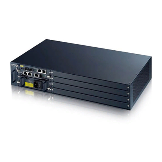
2.1 Appearance The IES supports DC or AC power supply. The following figure shows the IES chassis with cards, the MSC1002G/MSC1401G management card, and the IES4005M-DC installed. (If you need information on the IES with AC power supply, refer to Chapter 4 on page 36.) - Page 18 • The frame ground is on the upper left of the chassis front panel. • Connect the frame grounds to a building’s protective earthing terminals using a green-and-yellow frame ground wire. Warning! Bond the frame ground before you connect any other cables or wiring. Figure 5 Bonding #2 Phillips IES4005M User’s Guide...
-
Page 19: System Overview
• Connect the public switched telephone network (PSTN/ISDN) or a VOP1164G-61’s port to the POTS port on an xDSL line card to provide voice and DSL service to the line card’s subscribers. • The management card connects to and monitors the fan module through the backplane. IES4005M User’s Guide... - Page 20 Chapter 2 IES Chassis IES4005M User’s Guide...
-
Page 21: Chapter 3 Management Cards
IES’s voltage or temperature is outside of the normal range. The IES has not detected an alarm on itself. The following LEDs apply to the SFP slots. Green The IES is ranged. Blinking The IES is ranging. There is no connection to the PON. IES4005M User’s Guide... -
Page 22: Msc1401G Ports
This RJ-45 connector is for connecting to alarm output terminals on other equipment. CONSOLE2 This RJ-45 RS-232 port is for connecting to a UPS. When you deploy the IES4005M with a UPS, only the POTS modules function during a power outage so subscribers can still make emergency calls. -
Page 23: The Msc1002G Management Card
The port is transmitting/receiving to/from a 100 Mbps Ethernet network. A 100 Mbps Ethernet link is up. The Ethernet link is down. Green Blinking The port is transmitting/receiving to/from a 10 Mbps Ethernet device. A 10 Mbps Ethernet link is up. The Ethernet link is down. IES4005M User’s Guide... -
Page 24: Msc1002G Ports
This RJ-45 connector is for connecting to alarm output terminals on other equipment. CONSOLE2 This RJ-45 RS-232 port is for connecting to a UPS. When you deploy the IES4005M with a UPS, only the POTS modules function during a power outage so subscribers can still make emergency calls. -
Page 25: Msc1002G Specifications
Note: The alarm input is only for dry contact without any power. The IES signals an alarm when it detects an alarm on the ALARM input pins, the IES4005M is overheated, the voltage readings are outside the tolerance levels, a fan failed, or another alarm occurs. -
Page 26: Gigabit Ethernet Interfaces
For transceivers with a flip-up or flip-down latch, close the latch. Insert the fiber-optic cables into the transceiver (you may need to remove cable dust covers). Insert the transceiver into the slot with the exposed section of PCB board facing down. IES4005M User’s Guide... -
Page 27: Console1 Port Pin Assignment
Put the transceiver’s dust cover on the transceiver. Figure 10 Removing a Transceiver 3.2.7 CONSOLE1 Port Pin Assignment Use this mini RJ-11 port for local management of the IES. Figure 11 CONSOLE1 Mini RJ-11 Female Connector PIN4 PIN1 IES4005M User’s Guide... -
Page 28: Console2 Port Pin Assignment
Figure 12 CONSOLE2 RJ-45 Female Connector PIN8 PIN1 Table 9 CONSOLE2 Port PIN Layout PIN NO. NAME NOTE RS-232 for UPS RS-232 for UPS RXD-PON RXD-UPS RS-232 for UPS TXD-UPS RS-232 for UPS TXD-PON RS-232 for UPS IES4005M User’s Guide... -
Page 29: Chapter 4 Line Cards
The ALC1132G-51 card provides up to 32 ADSL2+ lines for data and IPTV services and includes internal splitters. This card is hot-swappable. 4.2.1 Front Panel The following figure shows the front panel of ALC1132G-51. Figure 13 ALC1132G-51’s Front Panel LEDs IES4005M User’s Guide... -
Page 30: Ports
One 32-line POTS port with Telco 64 connector 4.2.3 Pin Assignments The line card Telco 64 connectors (also known as Champ 64) are female. The following figure and table describe the pinouts of the Telco 64 connectors. IES4005M User’s Guide... - Page 31 ADSL2+ pair 26 POTS pair 27 ADSL2+ pair 27 POTS pair 28 ADSL2+ pair 28 POTS pair 29 ADSL2+ pair 29 POTS pair 30 ADSL2+ pair 30 POTS pair 31 ADSL2+ pair 31 POTS pair 32 ADSL2+ pair 32 IES4005M User’s Guide...
-
Page 32: Specifications
4.3.2 Ports This table describes the ports on VLC1132G-51’s front panel. Table 16 VLC1132G-51 Port Descriptions LABEL DESCRIPTION VDSL(1-32) One 32-line data and voice port with Telco 64 connector POTS One 32-line POTS port with Telco 64 connector IES4005M User’s Guide... -
Page 33: Pin Assignments
VDSL2 pair 21 POTS pair 22 VDSL2 pair 22 POTS pair 23 VDSL2 pair 23 POTS pair 24 VDSL2 pair 24 POTS pair 25 VDSL2 pair 25 POTS pair 26 VDSL2 pair 26 POTS pair 27 VDSL2 pair 27 IES4005M User’s Guide... -
Page 34: Specifications
Table 19 VOP1164G-61 LED Descriptions COLOR STATUS DESCRIPTION Green The line card is turned on. The line card is turned off or has failed. The line card has a critical alarm. The line card is operating normally. IES4005M User’s Guide... -
Page 35: Ports
POTS pair 46 POTS pair 15 POTS pair 47 POTS pair 16 POTS pair 48 POTS pair 17 POTS pair 49 POTS pair 18 POTS pair 50 POTS pair 19 POTS pair 51 POTS pair 20 POTS pair 52 IES4005M User’s Guide... -
Page 36: Specifications
4.5 Power Consumption The following table gives example general IES power consumption information. Table 23 Example General Power Consumption Specifications ITEM VALUE Maximum system power IES4005M-DC: 468 Watts IES4005M-AC: 600 Watts VLC1132G-51 (32) 17a 39.2 Watts ALC1132G-51 (32) 33.5 Watts VOP1164G-61 (standby) (64) 22.92 Watts... - Page 37 Chapter 4 Line Cards Table 23 Example General Power Consumption Specifications ITEM VALUE Battery voltage 35 V Loop current 20 mA IES4005M User’s Guide...
- Page 38 Chapter 4 Line Cards IES4005M User’s Guide...
-
Page 39: Chapter 5 Power Supply Unit
The power module is turned on and receiving power. The power module is turned off or not receiving power. 5.1.2 Port The port of the IES4005M-AC is located on the front panel. This table describes the port. Table 25 IES4005M-AC Port Descriptions PORT... -
Page 40: Specifications
The power module is turned on and receiving power. The power module is turned off or not receiving power. 5.2.2 Connectors The port of the IES4005M-DC is located on the front panel. This table describes the connector. Table 28 IES4005M-DC Port Descriptions CONNECTOR... -
Page 41: Specifications
IES4005M-DC’s power consumption. 5.2.4 Procedure to Connect the DC Power When installing the IES power wires on the IES4005M-DU, push the wires firmly into the terminals as deep as possible and make sure that no exposed (bare) wires can be seen or touched. - Page 42 Chapter 5 Power Supply Unit IES4005M User’s Guide...
-
Page 43: Chapter 6 Fan Module
6.2.2 Monitoring The fan module monitors to detect whether the fans are operating in the normal state and relays the information to the IES’s management card. IES4005M User’s Guide... -
Page 44: Deployments
70~74 0x20 (12.5%) Fan 1 5000 Fan 2 4500 Fan 3 5000 75~84 0x40 (25%) Fan 1 6000 Fan 2 5000 Fan 3 6000 Above 85 0xff (100%) Fan 1 6800 Fan 2 5400 Fan 3 6800 IES4005M User’s Guide... -
Page 45: Alarm Thresholds
This section provides the physical specifications for the fan module. Table 31 Fan Module Specifications ITEM VALUE Dimensions (W x D x H) 28.4 mm (W) x 225 mm (D) x 88.9 mm (H) Weight 408 g Maximum power consumption 19 Watts IES4005M User’s Guide... - Page 46 Chapter 6 Fan Module IES4005M User’s Guide...
-
Page 47: Chapter 7 Cables
The connections are as follows: • The end of the power cord with the PHS-301RL connector connects to the AC power input connector of the IES4005M-AC. • The other end of the power cord connects to the AC power outlet. -
Page 48: Specifications
AC input frequency range: 50 Hz to 60 Hz Max. input AC current: 6 A @ 100 V AC, 2.5 A @ 240 V AC Connector that connects to the IES4005M-AC PHS-301RL, female Connector that plugs into the AC power outlet... -
Page 49: Application
IES chassis. The connections are as follows: • One end of the power wires connects to the input on the DC input of the IES4005M-DU. • The other end of the power wires connect to the output port of the DC power supply. -
Page 50: Local Management Cable
• The DB-9 socket connects to a computer. 7.4.2 Appearance The following figure shows a local management cable. Figure 25 Mini RJ-11 DB-9 Cable 7.4.3 Pin Assignments The following diagram and chart show the pin assignments of the cable. IES4005M User’s Guide... -
Page 51: Specifications
IES’s upstream data connection. A straight-through or crossover Ethernet LAN cable connects the IES’s MGMT port to a computer or network for out of band maintenance and management. 7.5.2 Appearance The following figure shows an Ethernet LAN cable. IES4005M User’s Guide... -
Page 52: Pin Assignments
1 and 2 and to pins 3 and 6 are twisted pairs. Table 38 Crossover Ethernet LAN Cable PIN Layout X1 PIN TIP COLOR X2 PIN White and orange Orange White and green Blue White and blue Green White and brown Brown IES4005M User’s Guide... -
Page 53: Specifications
7.6.2 Appearance The following figure shows a one RJ-45 to two DB-9 cable. Connect the DB-9 connector labeled MB to a UPS. At the time of writing, the MSC1002G does not use the other DB-9 connector (labeled DB). IES4005M User’s Guide... -
Page 54: Pin Assignments
Wire diameter of the inner conductor 0.8 mm Wire gauge of the inner conductor 26 AWG Number of wires 7.7 Telco 64 Subscriber Cables Telco 64 subscriber cables connect the line cards for transmitting data and audio signals. IES4005M User’s Guide... -
Page 55: Application
Figure 30 Telco 64 Subscriber Cable with Telco 64 Connector and RJ-11 Connectors 7.7.3 Pin Assignments Section 4.2.3 on page Section 4.3.3 on page 33, and Section 4.4.3 on page 35 for the pin layout of the Telco 64 subscriber cables. IES4005M User’s Guide... -
Page 56: Specifications
The SFP slots have priority over the Gigabit ports. This means that if a SFP transceiver and the corresponding Gigabit port are connected at the same time, the Gigabit port will be disabled. 7.8.1.1.1 Appearance The following figure shows a duplex fiber optic cable with LC connectors. IES4005M User’s Guide... -
Page 57: Specifications
Class B+ GPON SFP optical, ITU-T G.984.2 and ITU-T G.984.5 compliant. Applications • Access Networks • Fiber to the Home, Curb, Office (FTTx) • Point to Multipoint Service (P2MP) • ITU-T G.984.2 • ITU-T G.984.5 • FSAN Class B+ • IEEE 802.3ah IES4005M User’s Guide... - Page 58 Chapter 7 Cables IES4005M User’s Guide...
-
Page 59: Hardware Installation
• If you are facing the IES front panel, the fan tray located in the left of the IES chassis houses three fans to blow air for ventilation. Cool air enters the chassis through intake vents on the left side panel and flows towards the right side where it exits. IES4005M User’s Guide... -
Page 60: Connecting The Ies Frame Ground
• The IES frame ground is on the upper left corner of the front panel. • Connect the frame grounds to a building’s protective earthing terminals using a green-and-yellow frame ground wire. IES4005M User’s Guide... -
Page 61: Card Installation
MSC all the way in and properly seated in the backplane. Make sure the front panel of the MSC is touching the front panel of the chassis. The MSC must be installed properly in order for you to be able to tighten the thumbscrews. IES4005M User’s Guide... - Page 62 Chapter 8 Hardware Installation Tighten the two thumbscrews. Figure 35 Installing a Line Card IES4005M User’s Guide...
-
Page 63: Removing Msc And Line Cards
MSC clear of the main chassis. Grasp the center of the front panel of the card with one hand and place the other hand under the card to support it. Slide the card out of the slot. IES4005M User’s Guide... - Page 64 Chapter 8 Hardware Installation Figure 36 Removing a Line Card IES4005M User’s Guide...
-
Page 65: Part Ii Commands
Commands... -
Page 67: Chapter 9 The Cli
Table 46 Default Out Of Band Management IP Address and Subnet Mask SETTING DEFAULT VALUE IP Address 192.168.0.1 Subnet Mask 255.255.255.0 Make sure your computer IP address is in the same subnet, unless you are accessing the IES through one or more routers. IES4005M User’s Guide... -
Page 68: Remote Access By Telnet
Configure the computer’s IP address and subnet mask as 192.168.1.100 and 255.255.255.0. Open a Telnet session to the IES’s IP address. Table 47 Default in band management IP address, subnet mask, and VLAN ID SETTING DEFAULT VALUE IP Address 192.168.1.1 Subnet Mask 255.255.255.0 VLAN ID IES4005M User’s Guide... -
Page 69: Logging In
, the full command of automatically [TAB] config configure displays. If you enter a partial command that is not unique and press , the IES displays a list of [TAB] commands that start with the partial command. IES4005M User’s Guide... -
Page 70: Common Command Notation
You can specify individual ports on the cards in different slots, for example 1/1,1/3,2/1,2/3 Use * to specify all of a line card’s ports: 1/*,2/1,2/3 You can also include a range of ports: 1/1-1/12 The VLAN ID on the UNI (User Network Interface) ports, 1-4093. uni-vlan IES4005M User’s Guide... -
Page 71: Command Summary
• E: The command is available in enable mode. It is also available in user mode if the level (P) is less than 13. • C: The command is available in config (not indented) or one of the config- (indented) modes. IES4005M User’s Guide... -
Page 72: Privilege Levels, Accounts And Passwords
Removes the specified account. no logins username <name> Changes the administrator password. The password and confirmation admin-password <password> string must be exactly the same. <confirm-string> password: Up to 31 printable characters. confirm-string: Type the password again for confirmation purpose. IES4005M User’s Guide... -
Page 73: Command Example
The administrator logs out and then logs in to a user account (for example, tom) for testing whether the enable password works. ras# config ras(config)# password ies7 ras(config)# aaa authentication enable local ras(config)# exit ras# exit User name: tom Password: **** ras# enable Password: ras# IES4005M User’s Guide... -
Page 74: Privilege Levels For Login Accounts
This command raises the session’s privilege level to the specified level. It also changes the session to enable mode, if the specified level is 13 or 14. This command is available in user mode or enable mode, and users have to know the password for the specified privilege level. IES4005M User’s Guide... -
Page 75: Command Modes
If the session’s privilege level is 13-14, the allowed commands are in one of these modes. Table 55 Command Modes for Privilege Levels 13-14 MODE PROMPT DESCRIPTION enable Displays current configuration, diagnostics, ras# maintenance. configuration Configures features other than those below. ras(config)# IES4005M User’s Guide... -
Page 76: Dual Image Files
Note: You should save your changes after each CLI session. All unsaved configuration changes are lost once you restart the IES. 9.11 Logging Out Enter the exit command in configure mode to go to mode. IES4005M User’s Guide... - Page 77 Chapter 9 The CLI Enter the exit command in enable mode to log out of the CLI. See Section 9.7 on page 75 for more information about modes. IES4005M User’s Guide...
- Page 78 Chapter 9 The CLI IES4005M User’s Guide...
-
Page 79: Chapter 10 Initial Setup
10.3 Changing the Management IP Address This command changes the management IP address for remote access. ip inband address <ip-address>/<mask> or this command changes the management IP address for local access. ip outband address <ip-address>/<mask> IES4005M User’s Guide... -
Page 80: Changing The Management Vlan
VLAN ID in order to perform management. This example sets the VLAN ID 3 for managing the system (the “management” or “CPU” VLAN). ip inband mgmt-vlan 3 Note: Remote access could be affected. IES4005M User’s Guide... -
Page 81: Looking At Basic System Information
1/0 dscp 2/0 dscp 3/0 dscp 4/0 dscp 5/0 dscp 6/0 dscp 7/0 dscp 8/0 dscp 9/0 dscp 10/0 dscp 11/0 dscp 12/0 dscp 13/0 dscp 14/0 dscp 15/0 < press any key to continue > IES4005M User’s Guide... -
Page 82: Provisioning Slots
You can check the status of all slots using the show lcman command. After you configure the slot for a type of line card, you can only use that type of line card in the slot. Any other type of line card will not be active. IES4005M User’s Guide... -
Page 83: Chapter 11 Management
Specify where to send the alarm. snmp| ‘none’ disables alarm syslog|all|none target reports on this alarm condition. Specify the displaying order. forward|reverse : oldest entry displayed first forward : latest entry displayed first reverse Display more comprehensive alarm condition descriptions. detail IES4005M User’s Guide... - Page 84 IES reports alarms immediately. Sets the time interval (10-600 seconds) the alarm line-control interval <interval> IES uses for sending alarms about these ports. This applies when you enable alarm line-control on these ports. IES4005M User’s Guide...
- Page 85 (SNMP trap and SYSLOG). Has the IES report alarms for the ports at alarm line-control regular intervals instead of immediately. Turns off interval-based reporting of alarms so no alarm line-control the IES reports alarms immediately. IES4005M User’s Guide...
- Page 86 CPU usage. 0 ~ 100. Set the CPU overload alarm clear threshold lower than CPU overload alarm issue threshold. Configures the number of sample seconds alarm coa sample-seconds <seconds> used for monitoring for a CPU overload. seconds: 1 ~ 60 IES4005M User’s Guide...
-
Page 87: Date And Time Commands
GMT) and your time zone. : -1200-1200 in steps of 100 time-zone Enables daylight saving time. The current time is updated time daylight-saving-time if daylight saving time has started. Disables daylight saving time. no time daylight-saving-time IES4005M User’s Guide... -
Page 88: Hardware Monitor Commands
This table describes the commands. Table 61 Hardware Monitor Commands Summary COMMAND DESCRIPTION Displays the system monitor settings. show hw-monitor Displays the system monitor statistics summary. show hw-monitor statistics [slot <slot>] is the control card. are the line cards. slot IES4005M User’s Guide... -
Page 89: Running Configuration Commands
Resets the IES to the factory default settings. erase running-config Resets the specified DSL ports to the factory default settings on a per- erase running-config port basis and optionally on a per-feature configuration basis. interface dsl <slot/portlist> [<attribute> [<...>]] IES4005M User’s Guide... - Page 90 Displays the current GE NNI configuration on a port-by-port basis. You show running-config interface can specify a single port <1>, all ports <*> or a list of ports <1,2>. ge-nni <portlist> You can also include a range of ports <1-2>. [<attribute> [<...>]] IES4005M User’s Guide...
-
Page 91: Command Examples
SNMP is a member of TCP/IP protocol suite. A manager station can manage and monitor the system through the network via SNMP version one (SNMPv1) and/or SNMP version 2c. The next figure illustrates an SNMP management operation. SNMP is only available if TCP/IP is configured. IES4005M User’s Guide... - Page 92 Allows the manager to set values for object variables within an agent. Trap Used by the agent to inform the manager of some events. Supported MIBs MIBs let administrators collect statistics and monitor status and performance. The system supports the following MIBs: • BRIDGE-MIB.mib • IF-MIB.mib IES4005M User’s Guide...
- Page 93 Sets the get community. Only for SNMPv2c or lower. snmp-server get-community <property> Sets the set community. Only for SNMPv2c or lower. snmp-server set-community <property> Sets the trap community. Only for SNMPv2c or lower. snmp-server trap-community <property> IES4005M User’s Guide...
-
Page 94: System Maintenance Commands
Restarts the system with the specified firmware image (1: ras-0, 2: ras-1). boot image <1|2> Displays the interactive help system. help Displays the firmware image file currently in use. show boot-image Displays general system information. show system-information IES4005M User’s Guide... -
Page 95: Ftp For Configuration And Firmware Files
This is the generic name for the firmware on the IES. ras-0 is image 1; ras-1 is image 2. ras-1 The IES supports dual firmware images, ras-0 and ras-1. It uses one firmware image at a time. IES4005M User’s Guide... -
Page 96: Ftp Command Line Procedure
(config.cfg) to the IES and renames it to “config”. Likewise get config config.cfg transfers the configuration file on the IES to your computer and renames it to “config.cfg”. See Table 67 on page for more information on filename conventions. Enter quit to exit the ftp prompt. IES4005M User’s Guide... -
Page 97: Aaa Commands
The following table describes some key differences between RADIUS and TACACS+. Table 68 RADIUS vs. TACACS+ RADIUS TACACS+ Transport Protocol UDP (User Datagram Protocol) TCP (Transmission Control Protocol) Encryption Encrypts the password sent for All communication between the IES and authentication. the TACACS+ server is encrypted. IES4005M User’s Guide... -
Page 98: Aaa Command Summary
For example, if you configure two servers and the timeout is 30 seconds, then the IES waits 15 seconds for a response from each server. Clears the specified accounting server’s settings. no aaa server accounting radius index <1|2> IES4005M User’s Guide... - Page 99 Resets both the enable and login authentication method settings to no aaa authentication their defaults. Resets the enable authentication method settings to the default. no aaa authentication enable Resets the login authentication method settings to the default. no aaa authentication login IES4005M User’s Guide...
- Page 100 Disables accounting for exec type events, such as recording no aaa accounting exec administrator’s login and logout events via the console port, Telnet or SSH. Disables accounting for command type events. no aaa accounting command Resets all accounting settings to their defaults. no aaa accounting IES4005M User’s Guide...
-
Page 101: Command Examples
IES’s local database. Then it displays the current authentication method settings. sysname# configure sysname(config)# aaa authentication login radius local sysname(config)# exit sysname# show aaa authentication login type method : method1 method2 method3 ------- ------- ------- radius local enable type method : method1 method2 ------- ------- local IES4005M User’s Guide... - Page 102 12 tacacs+ sysname(config)# aaa accounting update period 3 sysname(config)# exit sysname# show aaa accounting accounting update timeout: 3 minutes accounting system: method ------- radius accounting exec: method mode ------- ---------- radius start-stop accounting commands: privilege --------- IES4005M User’s Guide...
-
Page 103: Performance Management
15-minute period. <threshold> Configures the number of packets that were too big allowed to receive 15min-rxover-threshold in any 15-minute period. <threshold> Configures the number of fragmented frames allowed to receive in any 15min-rxfrag-threshold 15-minute period. <threshold> IES4005M User’s Guide... - Page 104 15-minute period. threshold <threshold> Configures the number of RTP packets that can be failed to be received 15min-rtprxlostpkts- by the IES in any 15-minute period. threshold <threshold> Configures specified VoIP UNI ports. interface voip <slot/portlist> IES4005M User’s Guide...
-
Page 105: Command Examples
Displays all IPv4 trusted host information. show remote-management Enters the sub-command mode for configuring the specified IPv4 remote-management <index> trusted host entry. Leaves the IPv4 trusted host configuration sub-command mode. exit Enables the IPv4 trusted host entry. active IES4005M User’s Guide... -
Page 106: Command Examples
1 ras(config-remote-management-1)# start-addr 172.16.37.0 end-addr --> 172.16.37.255 ras(config-remote-management-1)# service icmp telnet ftp ssh ras(config-remote-management-1)# exit ras# config ras(config)# remote-management 2 ras(config-remote-management-2)# start-addr 192.168.10.1 end-addr --> 192.168.10.1 ras(config-remote-management-2)# service snmp ras(config-remote-management-2)# exit ras(config)# exit ras# IES4005M User’s Guide... -
Page 107: Chapter 12 Line Card Management
After you provision the slot for a type of line card, you can only use that type of line card in the slot. Provisioning a slot with a wrong provision type cannot activate the slot. IES4005M User’s Guide... - Page 108 2 provision-type alc ras(config)# exit ras# show lcman f/w version: V3.60(UHM.0)b4 id state card type provision type uptime heat vol mon -- -------- ----------- -------------- ------------- ------------ Active MSC1002G 37:02 Init ALC1132G-51 ALC1132G-51 Idle VOP1164G-61 - ras# IES4005M User’s Guide...
-
Page 109: Chapter 13 Switch Features
Do not use the specified ACL profile for the ports. no acl <acl-profile> Displays ACL settings for the specified DSL ports. show interface dsl <slot/ portlist> acl Enters the sub-command mode for configuring the specified DSL interface dsl <slot/portlist> ports. Leaves the DSL port configuration. exit IES4005M User’s Guide... - Page 110 Specifies an IPv6 next header. next-header <next-header> next-header: 0 ~ 255 Specifies an IPv6 traffic class. traffic-class <traffic-class> traffic-class: 0 ~ 255 Specifies a layer 4 source port range. source-l4-port range <start- port> <end-port> start-port: 0-65535 end-port: 0-65535 IES4005M User’s Guide...
- Page 111 Limits the receiving rate for packets that match the profile. rate-limit <rate-limit> rate-limit: 32-100000 in kbps Disables rate limiting for matching packets. no rate-limit Changes the inner VLAN inner priority bit of matching packets to change-inner-pbit <pbit> the specified one. IES4005M User’s Guide...
-
Page 112: Command Examples
When the number of broadcast, multicast and/or DLF packets reaches the maximum allowed per second, the IES discards subsequent packets. Enable this feature to reduce broadcast, multicast and/or DLF packets in your network. You can specify limits for DLF and broadcast packets. IES4005M User’s Guide... -
Page 113: Daisy Chain Commands
You can set the aging time, flush the address table, show the learned entries count, display the address table, display the entries for specific ports, UNI VLANs, untagged UNI VLANs, set the maximum number of MAC entries for specific ports, configure a static unicast IES4005M User’s Guide... - Page 114 (1-4093) Displays the forwarding database table address table for untagged show fdb address-table uni-untag UNI VLANs. Displays the forwarding database address table for the specified show interface dsl <slot/ ports. portlist> fdb address-table IES4005M User’s Guide...
- Page 115 Allows only static MAC addresses. fdb static-mac-only Allows both static and dynamic MAC addresses. no fdb static-mac-only Displays the forwarding database settings and maximum MAC show interface dsl <slot/ entry counts for the specified DSL ports. portlist> fdb IES4005M User’s Guide...
-
Page 116: Ge Uplink Commands
Displays the current interface status for the specified ports. You show interface ge-nni <portlist> can specify a single port <1>, all ports <*> or a list of ports status <1,2>. You can also include a range of ports <1-2>. IES4005M User’s Guide... -
Page 117: Link Aggregation Commands
“down” and removed from the trunk. Set a short timeout (one second) for busy trunked links to remove disabled ports from the trunk group as soon as possible. Resets the LACP timeout to the default value. no dot3ad lacp-timeout IES4005M User’s Guide... -
Page 118: Loop Guard Commands
Enters the sub-command mode for configuring the specified DSL ports. C interface dsl <slot/portlist> Enables the specified port(s) on the IES. Use this to manually re- active activate a port disabled by loop guard. Enables loop guard. loopguard IES4005M User’s Guide... -
Page 119: Command Examples
2/1 loopguard LoopGuard Status: Enable Port Port LoopGuard Total Total Shutdown Status Status TxPkts RxPkts Pkts Time ---- -------- --------- -------- -------- ---- --------------------------- Inactive Enable 00:00:00 Thu. Jan. 01, 197 ras# IES4005M User’s Guide... -
Page 120: Port Isolation Commands
MAC address becomes the root switch. priority: 0~61440 in steps of 4096 (0, 4096, 8192, 12288, 16384, 20480, 24576, 28672, 32768, 36864, 40960, 45056, 49152, 53248, 57344 or 61440) default: 61440 Resets the RSTP priority to the default value. no rstp priority IES4005M User’s Guide... - Page 121 Displays the RSTP configuration for the specified Gigabit Ethernet show interface ge-nni <portlist> uplink ports. You can specify a single port <1>, all ports <*> or a rstp list of ports <1,2>. You can also include a range of ports <1-2>. IES4005M User’s Guide...
-
Page 122: Mirror Commands
<port> interface port. dsl <slot/dstport> mode <mode> Mirrors the specified traffic from an uplink GE port to a DSL mirror interface ge-nni <port> interface PVC on a DSL port. dsl <slot/dstport> atm-vc <vpi/vci> mode <mode> IES4005M User’s Guide... -
Page 123: Command Examples
13.10.2 Command Examples This example enables port mirroring and copies outgoing traffic from DSL slot 2 port 1 to uplink GE port 1. sysname# configure sysname(config)# mirror interface dsl 2/1 interface ge-nni 1 mode egress sysname(config)# exit sysname# IES4005M User’s Guide... - Page 124 Chapter 13 Switch Features IES4005M User’s Guide...
-
Page 125: Chapter 14 Adsl
VCs. VC Mux VC Mux is a type of encapsulation where, by prior mutual agreement, each protocol is assigned to a specific virtual circuit, for example, VC1 carries IP, VC2 carries IPX, and so on. VC-based IES4005M User’s Guide... -
Page 126: Atm Vc Commands Summary
Adds or configures the specified ATM VC on the DSL ports. atm-vc <vpi/vci> llc|vc priority <priority> [mvlan] : LLC encapsulation : VC-MUX encapsulation mvlan: Include this to have the specified ATM VC join MVLAN. Removes the specified ATM VC from the DSL ports. no atm-vc <vpi>/<vci> IES4005M User’s Guide... -
Page 127: Chapter 15 Dhcp
3046 for more details. The DHCP relay agent information feature adds an Agent Information field to the option 18, 37, or 82 field of the DHCP headers of client TCP/IP configuration request frames that the IES relays to a DHCP server. IES4005M User’s Guide... - Page 128 VLAN from the downlink network. Other DHCP packets, such as DHCP Offer, will be dropped. This can help prevent Denial-Of-Service (DOS) attacks through DHCP. DHCP transparent and L2 Agent cannot be enabled at the same time in a VLAN. IES4005M User’s Guide...
- Page 129 IES to add to the DHCP requests that it relays to a DHCP server. Table 88 on page 128 for more information. Disables the DHCP L2 Agent option 82 remote ID on the specified no dhcp l2agent opt82-remote-id VLAN. vlan <vid> IES4005M User’s Guide...
-
Page 130: Command Examples
DHCP on VLAN 100. Before this, you have to make sure DHCP L2 Agent is disabled on the VLAN. You can use the show dhcp vlan * command to check this. If DHCP L2 IES4005M User’s Guide... - Page 131 This example shows how to enable IP-MAC binding on DSL port 1 on the line card in slot 2, set the DHCP snooping database max lease count to 10, and display the DHCP snooping database and IES4005M User’s Guide...
- Page 132 1 overflow: 0 dhcpv4 discover offer request release ------- -------- -------- -------- -------- -------- dhcpv6 solicit advertise request reply renew rebind release ------- -------- --------- -------- -------- -------- -------- -------- dhcpv6 relay-forward relay-reply ------- ------------- ----------- ras# IES4005M User’s Guide...
-
Page 133: Chapter 16 Multicast
Note: The IES does not allow a subscriber port to send multicast traffic (except static multicast traffic) to an uplink port. Only the uplink port can forward multicast traffic to the subscriber port(s). IES4005M User’s Guide... - Page 134 Enables IGMP/MLD snooping. IGMP/MLD transparent, snooping, igmp-mld snooping proxy, and proxy-reporting can not enabled at the same time. Disables IGMP/MLD snooping. no igmp-mld snooping Enables IGMP/MLD proxy. IGMP/MLD transparent, snooping, igmp-mld proxy proxy, and proxy-reporting can not enabled at the same time. IES4005M User’s Guide...
- Page 135 Enables preview privilege for the group and configures the privilege preview <length> preview parameters. <interval> <count> <reset> : 10-300 in seconds length : 10-300 in seconds interval : 1-10 count : 30-86400 in seconds reset IES4005M User’s Guide...
- Page 136 <uni-vid>] Adds the specified DSL ports to an MVLAN and sends the egress igmp-mld mvlan <mvid> untag packets out untagged. Removes the specified DSL port from an MVLAN. no igmp-mld mvlan <mvid> IES4005M User’s Guide...
-
Page 137: Command Examples
Note: Before you can use an interface, you have to activate (provision) the corresponding slot. See Section 12.1.1 on page 107 for how to activate a slot. This example shows how to enable IGMP snooping on the IES with the following settings: • IGMP version 3 IES4005M User’s Guide... - Page 138 The multicast packets from upstream direction for IPv4 : forward The multicast packets from upstream direction for IPv6 : forward The unknown multicast packets for IPv4 : drop The unknown multicast packets for IPv6 : drop ras# IES4005M User’s Guide...
-
Page 139: Static Multicast Commands
Configures a static multicast group with no VLAN tagged. That is, smcast <mac> uni-untag the ports only accept untagged frames from the multicast group. Removes the specified static multicast group. no smcast <mac> Displays static multicast settings on the specified DSL ports. show interface dsl <slot/portlist> smcast IES4005M User’s Guide... -
Page 140: Command Examples
1 to VLAN 20 tagged frames. This example also sets the DSL port to only accept multicast frames of group 01:00:11:00:00:01 with VLAN 10 tags. sysname# config sysname(config)# interface dsl 2/1 sysname(config-interface-dsl-2/1)# vlan translation uni-vlan 10 svlan 20 sysname(config-interface-dsl-2/1)# smcast 01:00:11:00:00:01 uni-vlan 10 IES4005M User’s Guide... -
Page 141: Chapter 18 Ip
<mask> ip-address: 0.0.0.1 ~ 223.255.255.255 : 0-32 mask Sets the management IP address and subnet mask for the out-of- no ip outband band management port to the default values. The default value is 192.168.0.1 IES4005M User’s Guide... - Page 142 0.0.0.0 ~ 223.255.255.255, a domain-name is permitted for a VOIP interface voip: ping via VoIP interface rtp: ping via RTP interface size: 0-1472 -t: ping continuously until Ctrl-C is pressed Displays interface statistics. show ip statistics IES4005M User’s Guide...
-
Page 143: Chapter 19 Ipv6
In IPv6, an interface ID is a 64-bit identifier. It identifies a physical interface (for example, an Ethernet port) or a virtual interface (for example, the management IP address for a VLAN). One interface should have a unique interface ID. IES4005M User’s Guide... -
Page 144: Global Address
All routers on a local node. FF01:0:0:0:0:0:0:2 All hosts on a local connected link. FF02:0:0:0:0:0:0:1 All routers on a local connected link. FF02:0:0:0:0:0:0:2 All routers on a local site. FF05:0:0:0:0:0:0:2 All DHCP severs on a local site. FF05:0:0:0:0:0:1:3 IES4005M User’s Guide... - Page 145 MAC address and complements the seventh bit of the first byte of the MAC address. See the following example. Table 99 : 13 : 49 : 12 : 34 : 56 Table 100 EUI-64 : 13 : 49 : FF : FE : 12 : 34 : 56 IES4005M User’s Guide...
- Page 146 (S1) (from which the addresses in the IA_NA were obtained) a Renew message. If the time T2 is reached and the server does not respond, the client sends a Rebind message to any In IPv6, all network interfaces can be associated with several addresses. IES4005M User’s Guide...
- Page 147 The Neighbor Discovery Protocol (NDP) is a protocol used to discover other IPv6 devices and track neighbor’s reachability in a network. A neighbor is “reachable” means a neighbor solicitation message (from the IES) is responded with a neighbor advertisement message from the neighbor. IES4005M User’s Guide...
-
Page 148: Ipv6 Commands Summary
Displays packets’ default outgoing interface. show ip ipv6 default- management Sends Ping packets to the specified Ethernet device. ping ipv6 <ipv6-address> [size <size>] [-t] ipv6-address: 2000:: ~ 3fff:ffff:ffff:ffff:ffff:ffff:ffff:ffff size: 0 ~ 1472 : ping continuously until Ctrl-C is pressed IES4005M User’s Guide... -
Page 149: Chapter 20 Mtu
This table describes the commands. Table 102 MTU Commands Summary COMMAND DESCRIPTION Configures the maximum transmission unit. mtu <mtu> <mtu>: 512..2000 bytes Loads the default MTU setting. no mtu Displays the maximum transmission unit setting. show mtu IES4005M User’s Guide... - Page 150 Chapter 20 MTU IES4005M User’s Guide...
-
Page 151: Pppoe Intermediate Agent
Value, i1 and i2. The Value is the 32-bit number 0x00000DE9, which stands for the “ADSL Forum” IANA entry. i1 and i2 are PPPoE intermediate agent sub-options, which contain additional information about the PPPoE client. IES4005M User’s Guide... -
Page 152: Pppoe Intermediate Agent Commands Summary
Disables PPPoE packet transparent on the specified VLAN. no pppoe transparent vlan <vid> Enables PPPoE intermediate agent on the specified VLAN. PPPoE pppoe intermediate-agent vlan transparent and intermediate agent can not be enabled at the same <vid> time in a VLAN. IES4005M User’s Guide... -
Page 153: Command Examples
100 info %pid%cmac1 ras(config)# exit ras# show pppoe vlan 100 vid transparent intermediateagent Circuit ID Remote ID ---- ----------- ----------------- ---------- --------- Circuit ID info --------------- %slotid%pid%cvlan Remote ID info -------------- %pid%cmac1 ras# IES4005M User’s Guide... - Page 154 Offer) from the PPPoE. In this case you would check the connection between the IES and the PPPoE server. ras# pppoe test 2/1 uni-untag slot: 2 port: 1 start to PPPoE test ras# show interface dsl 2/1 pppoe test slot port status ---- ------ ------------------------------------------------------------------- receive PADO fail ras# IES4005M User’s Guide...
-
Page 155: Chapter 22 Qos
The DSCP value determines the PHB (Per-Hop Behavior), that each packet gets as it is forwarded across the DiffServ network. Based on the marking rule different kinds of traffic can be marked for different priorities of forwarding. Resources can then be allocated according to the DSCP values and the configured policies. IES4005M User’s Guide... -
Page 156: Command Examples
Quality of Service (QoS) refers to both a network’s ability to deliver data with minimum delay, and the networking methods used to control the use of bandwidth. Without QoS, all traffic data is equally likely to be dropped when the network is congested. This can cause a reduction in network IES4005M User’s Guide... - Page 157 The following table describes commonly used parameter notation for these commands. Table 109 QoS Command Parameters NOTATION DESCRIPTION The maximum rate. 32-100000 in kbps. Default 100000. rate Name of a profile. Use up to 31 printable characters. name The maximum number of packets, 30-255, default 255 depth IES4005M User’s Guide...
- Page 158 <depth> Configures the maximum rate queue 4 allows. queue4 max-rate <rate> depth <depth> Configures the maximum rate queue 3 allows. queue3 max-rate <rate> depth <depth> Configures the maximum rate queue 2 allows. queue2 max-rate <rate> depth <depth> IES4005M User’s Guide...
- Page 159 Maps pbit 0 to the specified queue. pbit0 <queue-id> Displays the pbit to queue ID mapping. show qos queue-mapping Enters the sub-command mode for configuring a VC shaping profile. qos vc-shaping-profile <name> Leaves the VC shaping profile sub-command mode. exit IES4005M User’s Guide...
-
Page 160: Command Examples
70 depth 255 ras(qos wrr-wfq-profile)# queue1 weight 70 depth 255 ras(qos wrr-wfq-profile)# queue0 weight 70 depth 255 ras(qos wrr-wfq-profile)# exit ras(config)# interface dsl 2/4 ras(config-interface-dsl-2/4)# qos algorithm wfq ras(config-interface-dsl-2/4)# qos weight-profile test ras(config-interface-dsl-2/4)# exit ras(config)# exit ras# IES4005M User’s Guide... - Page 161 75000 100000 100000 depth: ras# This example shows how to configure two VC-shaping profiles. One is EXAMPLE-50M with a maximum rate of 50000 kbps and a depth of 100 packets. The other one is EXAMPLE-75M with a IES4005M User’s Guide...
- Page 162 0/33 llc priority 0 ras(config-interface-dsl-2/*)# atm-vc 0/34 llc priority 1 ras(config-interface-dsl-2/*)# atm-vc 0/35 llc priority 2 ras(config-interface-dsl-2/*)# qos atm-vc 0/33 vc-shaping-profile EXAMPLE-75M ras(config-interface-dsl-2/*)# qos atm-vc 0/34 vc-shaping-profile EXAMPLE-50M ras(config-interface-dsl-2/*)# qos atm-vc 0/35 vc-shaping-profile EXAMPLE-50M ras(config-interface-dsl-2/*)# exit IES4005M User’s Guide...
-
Page 163: Chapter 23 Static Route
< > < > ip route <ip-address>/<mask> ip-address mask exists, the IES deletes the existing route first. <next-hop-ip> next-hop-ip: IP address of the next device. 0.0.0.0- 223.255.255.255 Removes a specified static route. no ip route <ip-address>/<mask> IES4005M User’s Guide... - Page 164 Chapter 23 Static Route IES4005M User’s Guide...
-
Page 165: Chapter 24 Vdsl
The optional band is used for upstream transmission which is to be negotiated during line initiation. The optional band frequency (for example, x and y) varies depending on the limit PSD mask you use. Figure 41 A Band Plan Example Frequency 3.75 (MHz) IES4005M User’s Guide... - Page 166 PSD of all lines based on a reference line length. This mitigates the upstream crosstalk on shorter loops to longer loops. It allows the switch to provide better service in a network environment with telephone wiring of varying lengths. IES4005M User’s Guide...
- Page 167 Besides, higher Line 1 PSD causes higher interference to the Line 2. CPE (B) receives signal with higher attenuation. With DPBO enabled on the CO (A), it decreases the PSD level and reduces the crosstalk impact on other service lines. IES4005M User’s Guide...
- Page 168 To avoid performance degradation due to RFI, set the switch to not transmit VDSL signals in the RFI band defined by the regulatory bodies (ETSI and ANSI). You can also configure your own RFI bands on the system. IES4005M User’s Guide...
-
Page 169: Vdsl Commands
0-32 in 0.5 symbol steps, default: 4. The upshift noise margin 0-310 in steps of 0.1dB, default: 90 upshift-nrm The downshift noise margin 0-310 in steps of 0.1dB, default: 30 downshift-nrm The rate adaption upshift time. 0-16383 in seconds, default: 30 upshift-time IES4005M User’s Guide... - Page 170 [name] specified or the contents of the specified DSL line profile. Enters the sub-command mode for configuring the specified DSL dsl line-profile <name> line profile. Leaves the DSL line profile configuration sub-command mode. exit IES4005M User’s Guide...
- Page 171 0- 200 or 255. 0 = -140dBm/Hz,-200 = -40 dBm/Hz in step of 0.5 dBm/Hz, 255 = 0 W/Hz Configures the downstream maximum nominal aggregation max-nor-atp-ds <tx-power> transmit power. tx-power: 0-255 in step of 0.1 dB, default: 200 IES4005M User’s Guide...
- Page 172 Configures the downstream virtual noise PSD level by defining the refvn-ds <carrier-index> <vn- break points (used for VDSL2 protocol). psd> [<carrier-index> <vn- psd> …] carrier-index: 0-4095 vn-psd: 0-200 or 255. 0 = -140dBm/Hz,-200 = -40 dBm/Hz in steps of 0.5 dBm/Hz, 255 = 0 W/Hz IES4005M User’s Guide...
- Page 173 0-2048. 0: 0KHz, 2048: 8832 KHz in steps of 4.3125 KHz default: 32 Configures the DPBO PSD mask used at exchange (used for dbpo-epsd <carrier-index> VDSL2 protocol). <epsd> [<carrier-index> <epsd> …] carrier-index: 0-4095 epsd: 0-190. scalar value 0--95dBm in steps of -0.5dBm IES4005M User’s Guide...
- Page 174 Displays the contents of the specified DSL alarm line profile. show dsl alarm-line-profile <name> Enters the sub-command mode for configuring the specified DSL dsl alarm-line-profile <name> alarm line profile. Leaves the DSL alarm line profile configuration sub-command exit mode. IES4005M User’s Guide...
- Page 175 15 minutes. 0- threshold <threshold> 2147483647, default: 0. Configures the number of corrected error blocks allowed on the xtuc-15min-corrected- system within 15 minutes. 0- 2147483647, default: 0. threshold <threshold> IES4005M User’s Guide...
- Page 176 Displays the current 15 minutes DSL line rate for the specified show interface dsl <slot/ DSL ports. portlist> linerate Displays the current 15 minutes DSL line status for the specified show interface dsl <slot/ DSL ports. portlist> status IES4005M User’s Guide...
- Page 177 Performs an OAM F5 loopback test on the specified ATM PVC of the dsl diagnostic oamf5 <slot/port> specified DSL port. <vpi/vci> Displays the OAM F5 loopback test results for the specified DSL show interface dsl <slot/ port. portlist> diagnostic oamf5 IES4005M User’s Guide...
- Page 178 Table 116 VDSL Commands Summary (continued) COMMAND DESCRIPTION Clears the packet statistics for the specified DSL ports. clear interface dsl <slot/ portlist> statistics Displays the packet statistics for the specified DSL ports. show interface dsl <slot/ portlist> statistics IES4005M User’s Guide...
-
Page 179: Chapter 25 Vlan
• VLAN modes can be applied to any logical port (PTM or ATM). • A logical port can join more than one VLAN mode, but the UNI VLAN used in each joined VLAN mode must be unique. IES4005M User’s Guide... -
Page 180: Transparent Vlan Mode
VLAN Tagging and S(VID a) C(VID a) interface dsl 2/1 Trunk (ATM-tagged) vlan trunk atm-vc 0/33 uni-vlan 100 25.1.3 Stacking VLAN Tagging and Trunk Mode • Compared to VLAN tagging and trunk mode this mode adds an outer tag. IES4005M User’s Guide... -
Page 181: Vlan Translation And Aggregation Mode
C(VID c) vlan translation uni-vlan 102 svlan 1100 VLAN Aggregation S(VID y) C(VID b) interface dsl 2/1 (ATM) vlan translation atm-vc 0/33 uni-vlan 101 svlan 1100 S(VID y) C(VID c) vlan translation atm-vc 0/33 uni-vlan 102 svlan 1100 IES4005M User’s Guide... -
Page 182: Stacking Vlan Translation And Aggregation Mode
2/1 (PTM) vlan tls svlan 1000 spbit 3 S(TLSVID) + C(VID a) C(VID a) VLAN TLS S(TLSVID) untag interface dsl 2/1 (ATM) vlan tls atm-vc 0/33 svlan 1000 spbit 3 S(TLSVID) + C(VID a) C(VID a) IES4005M User’s Guide... -
Page 183: Multicast Vlan
0/33 vc priority 0 mvlan 25.1.8 Management and VoIP VLAN • The management VLAN and VoIP VLAN both accept only single tagged packets on both the NNI and CPU ports. • UNI ports cannot communicate with the CPU port. IES4005M User’s Guide... -
Page 184: General Vlan Commands
VLAN transparent traffic can go through the uplink. Removes the Gigabit Ethernet uplink ports from all VLANs joined by no vlan all using the vlan all command. 25.2.1 Command Examples Section 9.1.3 on page 68 for an example about how to change STPID. IES4005M User’s Guide... -
Page 185: Transparent Vlan Commands
VLAN and command examples. Note: Use the interface ge-nni <portlist> and vlan all commands to add Gigabit Ethernet uplink ports to all VLANs (1 ~ 4093) to make sure VLAN transparent traffic can go through the uplink. IES4005M User’s Guide... -
Page 186: Command Examples
VLANs, for many different customers. A service provider’s customers may require a range of VLANs to handle multiple applications. A service provider’s customers can assign their own inner VLAN tags to traffic. The service provider IES4005M User’s Guide... - Page 187 If specified, untagged, priority tagged, and C tagged frames will adopt the S priority bit in upstream traffic. Disables Transparent LAN service on the specified DSL ATM virtual no vlan tls atm-vc <vpi>/ circuit. <vci> IES4005M User’s Guide...
-
Page 188: Command Examples
The VCI (Virtual Channel Indicator) 32-65535. This table describes the commands. Table 131 VLAN Translation and Aggregation Commands Summary COMMAND DESCRIPTION Enters the sub-command mode for configuring the specified DSL ports. C interface dsl <slot/portlist> Leaves the DSL port configuration. exit IES4005M User’s Guide... -
Page 189: Command Examples
11 svlan 1 ras(config-interface-dsl-2/5)# vlan translation uni-vlan 13 svlan 3 ras(config-interface-dsl-2/5)# exit ras(config)# interface dsl 2/6 ras(config-interface-dsl-2/6)# active ras(config-interface-dsl-2/6)# vlan translation uni-vlan 21 svlan 1 ras(config-interface-dsl-2/6)# vlan translation uni-vlan 23 svlan 3 ras(config-interface-dsl-2/6)# exit ras(config)# ras# IES4005M User’s Guide... -
Page 190: Vlan Trunk Commands
S VLAN or S + C VLAN on uplink ports. <vci> uni-untag svlan <svid> spbit <spbit> [cvlan <cvid> cpbit <cpbit>] Removes the cross-connection of untagged packets in the specified no vlan trunk atm-vc <vpi>/ DSL ATM virtual circuits. <vci> uni-untag IES4005M User’s Guide... -
Page 191: Command Examples
S VLAN 200 and C VLAN 100 on it. Both the S priority bits of S VLAN and C VLAN are set to 0. ras# config ras(config)# interface dsl 2/7 ras(config-interface-dsl-2/7)# active ras(config-interface-dsl-2/7)# vlan trunk uni-untag svlan 200 spbit 0 cvlan 100 cpbit 0 ras(config-interface-dsl-2/7)# exit ras(config)# exit ras# IES4005M User’s Guide... - Page 192 Chapter 25 VLAN IES4005M User’s Guide...
-
Page 193: Chapter 26 Voip
The voice traffic and H.248 signaling from the IES are sent to the OLT or the active Gigabit Ethernet backbone network. An external MGC or H.248 voice gateway converts the voice traffic to other formats as required. IES4005M User’s Guide... -
Page 194: Voip Commands
The following table describes commonly used parameter notation for these commands. Table 134 VoIP Command Parameters NOTATION DESCRIPTION The name of a profile, up to 31 printable characters. profile-name The name of a profile, up to 31 printable characters. name IES4005M User’s Guide... - Page 195 16: Poland 39: South Korea 17: Portugal 40: Philippines 18: Slovakia 41: India 19: Spain 42: Turkey 20: Sweden 43: Vietnam 21: Switzerland 44: Brazil 22: UK default: 36 China Displays country code information. show voip countrycode IES4005M User’s Guide...
- Page 196 Configures the value of the DSCP bit (0-63) carried on H.248 packets. dscp <dscp> Default:48 Configures the text encoding type of the H.248 messages the IES encode long|short sends out. : long text encoding long : short text encoding short default: long text IES4005M User’s Guide...
- Page 197 Enables RFC2833 DTMF relay. The system transmits DTMF signals as rfc2833 voice (in-band) or as separate RFC 2833 packets (out-of-band) according to the MGC's configuration. Disables RFC2833 DTMF relay. The system transmits DTMF signals as no rfc2833 voice (in-band). IES4005M User’s Guide...
- Page 198 Disables the DHCP client function on the interface if it is enabled. <mask> vlan <vid> [pbit <pbit>] ip-address: 1.0.0.0 ~ 223.255.255.255 Configures the VoIP interface as a DHCP client. voip ip address dhcp vlan <vid> [pbit <pbit>] IES4005M User’s Guide...
- Page 199 Removes reference to a VoIP DSP profile for voice band data service. no vbd-dsp-profile The voice band data service will refer to the VoIP DSP profile used for voice service. Clears call statistics. clear call-statistics Enables a VoIP port. active Disables a VoIP port. no active IES4005M User’s Guide...
- Page 200 <max- register its use. time> <min-time> max-time: 20-1500 milliseconds min-time: 20-1500 milliseconds default: not specified (use the value defined in the current selected country code). Use the value defined in the current selected country code. no hook-flash-time IES4005M User’s Guide...
- Page 201 Disables echo cancellation for normal voice service. echo-cancel inactive Enables echo cancellation for normal voice service. no echo-cancel inactive Configures the voice packet interval for the G.711 codec for normal g711vpi <vpi> voice service. vpi: 10, 20, 30 or 40 milliseconds default: 20 IES4005M User’s Guide...
-
Page 202: Command Examples
• The IP address, VLAN and priority for VoIP interface: 192.168.2.10/24, VLAN 200, priority 7 • MGC IP address: 192.168.2.100 • MG name: MG1_2U • Termination IDs of ports 1 and 2 of the VoIP line card on slot 3: term1_1 and term1_2 • DSP profile: DEFVAL IES4005M User’s Guide... - Page 203 Test your configuration by making a call from a phone connected to the port you configured. Alternatively, use the show interface voip <slot>/<portlist> linestat command to check whether the relevant port is successfully registered with the MGC (the state should be “idle”). IES4005M User’s Guide...
- Page 204 Chapter 26 VoIP IES4005M User’s Guide...
-
Page 205: Ieee 802.1X Authentication
%dmac2: MAC address of the host device in XXXXXXXXXXXX format where X=0-F %dmac3: MAC address of the host device in Bytes %phtype: ATM: atm, Ethernet: eth %hmodel: model name of the host device %fwid: host device firmware ID %blank: blank character IES4005M User’s Guide... - Page 206 Resets the 802.1x re-authentication period to the default. no dot1x period Disables the DHCP option 82 on the ports. no dot1x circuit-id IES4005M User’s Guide...
-
Page 207: Command Examples
RADIUS server set in entry 2 for port authentication. Then it sets the 802.1x authentication option to auto and reauthentication time interval to 28800 seconds (=8 hours). Finally, it displays the 802.1x authentication settings and statistics. IES4005M User’s Guide... - Page 208 ---- ------ ------------ ------ ------------- ---------- ------------ auto 28800 auto 28800 auto 28800 auto 28800 auto 28800 auto 28800 auto 28800 auto 28800 auto 28800 auto 28800 sysname# IES4005M User’s Guide...
- Page 209 0000 sysname(config)# dot1x userprofile name manager password 0000 sysname(config)# dot1x authentication userprofile sysname(config)# exit sysname# show dot1x userprofile User profile list: Name Password ------------------------------- ------------------------------- manager 0000 user 0000 IES4005M User’s Guide...
- Page 210 Chapter 27 IEEE 802.1x Authentication IES4005M User’s Guide...
-
Page 211: Part Iii: Troubleshooting, Specifications, Appendices, And Index
Troubleshooting, Specifications, Appendices, and Index... -
Page 213: Hardware Troubleshooting
Make sure you understand the normal behavior of the LED. See Section 6.4 on page Check the hardware connections. See Chapter 8 on page Inspect your cables for damage. Replace any damaged cables. If the problem continues, contact your vendor. IES4005M User’s Guide... -
Page 214: Ies Access And Login
If you were using the out-of-band management port, try the in-band management port. The default in-band IP address is 192.168.1.1. The default out-of-band IP address is 192.168.0.1. Use the CONSOLE1 port to log into the IES. IES4005M User’s Guide... - Page 215 Make sure you use terminal emulation software with the correct settings. The default settings are VT100 terminal emulation, 115200 bps, No parity, 8 data bits, 1 stop bit, and no flow control; although you can use the commands to configure the console port speed. IES4005M User’s Guide...
-
Page 216: Data Transmission
A DSL port’s connection speed is also limited by what the line card can support. 28.4 Management Lockout You could lock yourself (and all others) out from the IES by: Misconfiguring the text configuration file. Forgetting the password. Misconfiguring the management IP address. IES4005M User’s Guide... -
Page 217: A Line Card Does Not Become Active
If you forget your password or cannot access the IES, contact customer support for how to reset your device to the factory defaults. 28.6.1 Resetting the Defaults Via CLI Command If you know the password, you can reload the factory-default configuration file via Command Line Interface (CLI) command. Use the following procedure. IES4005M User’s Guide... -
Page 218: Recovering The Firmware
This is an example Xmodem configuration upload using HyperTerminal. Click Transfer, then Send File to display the following screen. Figure 46 Example Xmodem Upload Type the firmware file's location, or click Browse to search for it. Choose the 1K Xmodem protocol. Then click Send. IES4005M User’s Guide... -
Page 219: No Voice On A Dsl Connection
Make sure the in-house wiring works and is connected properly. Repeat the steps above using a different DSL port. 28.8 No Voice on a VoIP Connection Check the POTS and line card connections between the subscriber, the MDF(s) and VOP1164G-61. IES4005M User’s Guide... - Page 220 Chapter 28 Hardware Troubleshooting IES4005M User’s Guide...
-
Page 221: Product Specifications
Make sure you use wires of the specified wire gauge. Ground wire: 18 AWG Telephone wire: 26 AWG Power wire: 16 AWG or larger (two pairs of wires are required to support full power) Power consumption IES4005M-DC: 468 Watts (Max) IES4005M-AC: 600 Watts Backplane Total bandwidth: 8 GB Operating Temperature -40°C ~ 65°C;... -
Page 222: Firmware Naming Conventions
A firmware version includes the model code and release number as shown in the following example. Firmware Version: V3.60(UHM.0) "UHM" is the model code. "0" is this firmware's release number. This varies as new firmware is released. Your firmware's release number may not match what is displayed in this User's Guide. IES4005M User’s Guide... -
Page 223: Appendix A Customer Support
• Brief description of the problem and the steps you took to solve it. Corporate Headquarters (Worldwide) Taiwan • ZyXEL Communications Corporation • http://www.zyxel.com Asia China • ZyXEL Communications (Shanghai) Corp. ZyXEL Communications (Beijing) Corp. ZyXEL Communications (Tianjin) Corp. • http://www.zyxel.cn India • ZyXEL Technology India Pvt Ltd • http://www.zyxel.in Kazakhstan •... - Page 224 • ZyXEL Singapore Pte Ltd. • http://www.zyxel.com.sg Taiwan • ZyXEL Communications Corporation • http://www.zyxel.com Thailand • ZyXEL Thailand Co., Ltd • http://www.zyxel.co.th Vietnam • ZyXEL Communications Corporation-Vietnam Office • http://www.zyxel.com/vn/vi Europe Austria • ZyXEL Deutschland GmbH • http://www.zyxel.de Belarus • ZyXEL BY • http://www.zyxel.by...
- Page 225 Appendix A Customer Support Belgium • ZyXEL Communications B.V. • http://www.zyxel.com/be/nl/ Bulgaria • ZyXEL България • http://www.zyxel.com/bg/bg/ Czech • ZyXEL Communications Czech s.r.o • http://www.zyxel.cz Denmark • ZyXEL Communications A/S • http://www.zyxel.dk Estonia • ZyXEL Estonia • http://www.zyxel.com/ee/et/ Finland • ZyXEL Communications •...
- Page 226 • ZyXEL Communications Poland • http://www.zyxel.pl Romania • ZyXEL Romania • http://www.zyxel.com/ro/ro Russia • ZyXEL Russia • http://www.zyxel.ru Slovakia • ZyXEL Communications Czech s.r.o. organizacna zlozka • http://www.zyxel.sk Spain • ZyXEL Spain • http://www.zyxel.es Sweden • ZyXEL Communications • http://www.zyxel.se Switzerland •...
- Page 227 • http://www.zyxel.com/ec/es/ Ecuador • ZyXEL Communication Corporation • http://www.zyxel.com/ec/es/ Middle East Egypt • ZyXEL Communication Corporation • http://www.zyxel.com/homepage.shtml Middle East • ZyXEL Communication Corporation • http://www.zyxel.com/homepage.shtml North America • ZyXEL Communications, Inc. - North America Headquarters • http://www.us.zyxel.com/ IES4005M User’s Guide...
- Page 228 Appendix A Customer Support Oceania Australia • ZyXEL Communications Corporation • http://www.zyxel.com/au/en/ Africa South Africa • Nology (Pty) Ltd. • http://www.zyxel.co.za IES4005M User’s Guide...
-
Page 229: Appendix B Legal Information
This publication is subject to change without notice. Trademarks ZyNOS (ZyXEL Network Operating System) is a registered trademark of ZyXEL Communications, Inc. Other trademarks mentioned in this publication are used for identification purposes only and may be properties of their respective owners. - Page 230 ZyXEL. This warranty shall not apply if the product has been modified, misused, tampered with, damaged by an act of God, or subjected to abnormal working conditions. IES4005M User’s Guide...
- Page 231 • Warning! To avoid risk of electric shock, remove only one card at a time and do not place fingers or objects inside the chassis. Cover empty slots with slot covers. • Energy Hazard Warning! Remove all metal jewelry, watches, and so on from your hands and wrists before serving this device. IES4005M User’s Guide...
- Page 232 Your product is marked with this symbol, which is known as the WEEE mark. WEEE stands for Waste Electronics and Electrical Equipment. It means that used electrical and electronic products should not be mixed with general waste. Used electrical and electronic equipment should be treated separately. IES4005M User’s Guide...
-
Page 233: Index
Downstream Power Back Off, see DPBO command DPBO bit number parameter Electrical Length common notation DS (Differentiated Services) IP address parameter MAC address parameter DSCP notation service level parameters what it does port parameter DSL profile slot parameter dual firmware 76, 94 IES4005M User’s Guide... - Page 234 Management Information Base, see MIB management switch card installation removing help (in the CLI) MGMT 22, 24 MGMT LEDs mini GBIC ports connection speed installation connector type fan module modes line cards MSA (MultiSource Agreement) IES4005M User’s Guide...
- Page 235 TCP port number telephone wire gauge Telnet (accessing the CLI) 67, 69 rack terminal emulation installation specifications trademarks Radio Frequency Interference, see RFI transceiver installation rate adaption transceiver removal recovering firmware transmission rate IES4005M User’s Guide...
- Page 236 Very High Speed Digital Subscriber Line 2, see VDSL2 Virtual Channel Indicator, see VCI Virtual Path Indicator, see VPI VLAN stacking voice mail Voice over IP see VoIP VoIP 71, 122, 186, 187, 188, 190 VT100 warranty note Weighted Round Robin Scheduling, see WRR IES4005M User’s Guide...
Need help?
Do you have a question about the IES4005M and is the answer not in the manual?
Questions and answers