ZyXEL Communications IES-1248-51V User Manual
Hd digital surveillance monitor
Hide thumbs
Also See for IES-1248-51V:
- Support notes (90 pages) ,
- Specifications (4 pages) ,
- User manual (654 pages)
Table of Contents
Advertisement
Quick Links
Advertisement
Table of Contents
Troubleshooting

Related Manuals for ZyXEL Communications IES-1248-51V


Summary of Contents for ZyXEL Communications IES-1248-51V
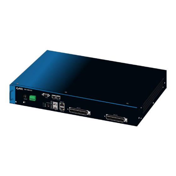
- Page 1 IES-1248-51V 48-port ADSL2+ remote IP DSLAM with embedded Media Gateway Default Login Details IP Address http://192.168.1.1 User Name admin Password 1234 www.zyxel.com Firmware Version 3.53 Edition 2, 03/2009 www.zyxel.com Copyright © 2009 ZyXEL Communications Corporation...
-
Page 3: About This User's Guide
Help us help you. Send all User Guide-related comments, questions or suggestions for improvement to the following address, or use e-mail instead. Thank you! The Technical Writing Team, ZyXEL Communications Corp., 6 Innovation Road II, Science-Based Industrial Park, Hsinchu, 300, Taiwan. E-mail: techwriters@zyxel.com.tw IES-1248-51V User’s Guide... -
Page 4: Document Conventions
Syntax Conventions • The IES-1248-51V may be referred to as the “IES”, the “device”, the “system” or the “product” in this User’s Guide. • Product labels, screen names, field labels and field choices are all in bold font. - Page 5 Document Conventions Icons Used in Figures Figures in this User’s Guide may use the following generic icons. The IES icon is not an exact representation of your IES. Computer Notebook computer Server DSLAM CPE Device Telephone Switch Router IES-1248-51V User’s Guide...
-
Page 6: Safety Warnings
• Do NOT obstruct the device ventilation slots, as insufficient airflow may harm your device. • Ensure that the fan filter is in place before switching on the IES. IES-1248-51V User’s Guide... - Page 7 • Fan Module Warning! Use the fan module handle when pulling out or pushing in the fan module. Be careful not to put fingers or objects inside the fan module. This product is recyclable. Dispose of it properly. IES-1248-51V User’s Guide...
- Page 8 Safety Warnings IES-1248-51V User’s Guide...
-
Page 9: Table Of Contents
MAC Filter ..........................211 Spanning Tree Protocol ......................213 Port Authentication ........................221 Port Security ..........................227 DHCP Relay ..........................229 DHCP Snoop ........................... 233 2684 Routed Mode ........................239 PPPoA to PPPoE ........................247 DSCP ............................253 IES-1248-51V User’s Guide... - Page 10 SNMP Commands ........................487 ADSL Commands ........................489 G.Bond ............................. 527 Virtual Channel Commands ..................... 531 ACL Commands ........................553 VoIP Commands ........................559 Firmware and Configuration File Maintenance ................ 583 Troubleshooting ........................589 Product Specifications ......................599 IES-1248-51V User’s Guide...
- Page 11 Contents Overview Appendices and Index ......................611 IES-1248-51V User’s Guide...
- Page 12 Contents Overview IES-1248-51V User’s Guide...
-
Page 13: Table Of Contents
2.3 Installation Scenarios ......................63 2.3.1 Desktop Installation Procedure .................. 63 2.3.2 Rack-Mounted Installation ..................64 2.4 Connecting the Frame Ground .................... 66 Chapter 3 Front Panel Connections ....................... 67 3.1 Front Panel .......................... 67 3.1.1 Front Panel Ports ....................... 67 IES-1248-51V User’s Guide... - Page 14 7.3 Accessing the Web Configurator ..................87 7.4 Navigation Panel ......................... 89 7.5 Changing Your Password ....................93 7.6 Saving Your Configuration ....................94 7.7 Logging Out of the Web Configurator .................. 94 Chapter 8 Initial Configuration ........................ 95 IES-1248-51V User’s Guide...
- Page 15 16.1 ADSL Standards Overview ....................131 16.2 Downstream and Upstream ..................... 131 16.3 Profiles ..........................131 16.4 Interleave Delay ....................... 132 16.4.1 Fast Mode ......................132 16.5 Configured Versus Actual Rate ..................132 16.6 Default Settings ....................... 133 IES-1248-51V User’s Guide...
- Page 16 19.2 Introduction to IEEE 802.1Q Tagged VLAN ..............175 19.2.1 Forwarding Tagged and Untagged Frames ............176 19.3 VLAN Status Screen ......................177 19.4 Static VLAN Setting Screen ..................... 179 19.5 VLAN Port Setting Screen ....................181 IES-1248-51V User’s Guide...
- Page 17 24.1 MAC Filter Introduction .....................211 24.2 MAC Filter Screen ......................211 Chapter 25 Spanning Tree Protocol......................213 25.1 RSTP and STP ........................ 213 25.2 Spanning Tree Protocol Status Screen ................216 25.3 Spanning Tree Protocol Screen ..................218 IES-1248-51V User’s Guide...
- Page 18 30.4 RPVC Arp Proxy Screen ....................244 30.5 2684 Routed Gateway Screen ..................245 Chapter 31 PPPoA to PPPoE........................247 31.1 PPPoA to PPPoE Overview .................... 247 31.2 PPPoA to PPPoE Screen ....................248 31.3 PPPoA to PPPoE Status Screen ..................251 IES-1248-51V User’s Guide...
- Page 19 37.2 Access Control Overview ....................273 37.3 SNMP ..........................274 37.3.1 Supported MIBs ..................... 275 37.3.2 SNMP Traps ......................275 37.4 SNMP Screen ........................278 37.5 Service Access Control Screen ..................279 37.6 Remote Management Screen ..................280 IES-1248-51V User’s Guide...
- Page 20 OUI Filter..........................313 42.1 OUI Filter Screen ......................313 Part IV: Routing Protocol, Alarm, VoIP and Management ....315 Chapter 43 Static Routing........................317 Chapter 44 Alarm............................319 44.1 Alarm ..........................319 44.2 Alarm Status Screen ......................319 IES-1248-51V User’s Guide...
- Page 21 45.10 Dialplan Screen ......................361 45.10.1 The Dialplan Profile Screen ................. 363 45.11 The Localcall Time Screen .................... 364 45.12 VoIP Line Status and Info Screen .................. 365 45.13 Diagnostic Screens ......................369 45.13.1 MLT Test Screen ....................369 IES-1248-51V User’s Guide...
- Page 22 Part V: Commands, Troubleshooting and Specifications ....389 Chapter 50 How to Access and Use the CLI ..................391 50.1 Accessing the CLI ......................391 50.1.1 Console Port ......................391 50.1.2 Telnet ........................391 50.1.3 SSH ........................392 50.2 Logging in ........................392 IES-1248-51V User’s Guide...
- Page 23 53.2.4 Alarm Tablelist Command Example ............... 417 53.2.5 Log Format ......................417 53.2.6 Alarm History Show Command Example ............... 418 53.2.7 Alarm History Clear Command Example ............... 418 53.2.8 Alarm XEdit Command Example ................418 Chapter 54 DHCP Commands ......................... 419 IES-1248-51V User’s Guide...
- Page 24 56.3.6 VLAN CPU Show Command Example ..............440 56.3.7 VLAN CPU Set Command Example ..............440 56.3.8 Configuring Management VLAN Example ............. 440 56.3.9 VLAN Delete Command Example ................441 56.3.10 VLAN Show Command Example ................. 441 56.4 VLAN Statistics Commands .................... 441 IES-1248-51V User’s Guide...
- Page 25 58.5.4 IGMP Count Show Command Example ..............453 58.6 IGMP Snoop Statistics Commands ................. 453 58.6.1 IGMP Snoop Info Statistics Command Example ............ 454 58.6.2 IGMP Group Statistics Command Example ............454 58.6.3 IGMP Port Info Statistics Command Example ............454 IES-1248-51V User’s Guide...
- Page 26 62.3 IP Bridge Edge Router Commands ................. 475 62.3.1 IP Bridge Edge Router Set Command Example ............ 475 62.3.2 IP Bridge Edge Router Show Command Example ..........476 62.3.3 IP Bridge Edge Router Delete Command Example ..........476 IES-1248-51V User’s Guide...
- Page 27 64.3.1 ADSL Profile Show Command Example ..............504 64.3.2 ADSL Profile Set Command Example ..............504 64.3.3 ADSL Profile Delete Command Example ............... 505 64.3.4 ADSL Profile Map Command Example ..............505 64.4 Statistics ADSL Commands ..................... 506 IES-1248-51V User’s Guide...
- Page 28 66.4.3 PPVC Member Delete Command Example ............537 66.4.4 PPVC Member Show Command Example ............. 537 66.4.5 PPVC Show Command Example ................537 66.4.6 PPVC Delete Command Example ................. 537 66.5 2684 Routed Mode Commands ..................538 66.5.1 2684 Routed Mode Example .................. 539 IES-1248-51V User’s Guide...
- Page 29 67.2.2 ACL Assignment Show Command Example ............558 Chapter 68 VoIP Commands........................559 68.1 General VoIP Command Parameters ................559 68.2 VoIP Show Commands ....................559 68.3 voip countrycode Commands ..................560 68.3.1 voip countrycode set Command Example .............. 562 IES-1248-51V User’s Guide...
- Page 30 69.2 Filename Conventions ..................... 583 69.3 Editable Configuration File ....................584 69.3.1 Editable Configuration File Backup ............... 584 69.3.2 Edit Configuration File ................... 585 69.3.3 Editable Configuration File Upload ................. 586 69.4 Firmware File Upgrade ....................587 Chapter 70 Troubleshooting........................589 IES-1248-51V User’s Guide...
- Page 31 71.4.3 Console Cable Pin Assignments ................610 Part VI: Appendices and Index ............611 Appendix A Changing a Fuse ....................613 Appendix B PSTN Parameters by Country ................615 Appendix C Legal Information ....................663 Appendix D Customer Support..................... 667 Index............................673 IES-1248-51V User’s Guide...
- Page 32 Table of Contents IES-1248-51V User’s Guide...
-
Page 33: List Of Figures
Figure 33 VC Setup ..........................99 Figure 34 Select Ports ..........................99 Figure 35 VC Setup ..........................100 Figure 36 Config Save .......................... 100 Figure 37 Config Save, Save Successful ..................... 100 Figure 38 Home ............................ 101 IES-1248-51V User’s Guide... - Page 34 Figure 76 Example of Using Multicast with VLAN ID Queries .............. 185 Figure 77 IGMP (Status) ........................186 Figure 78 IGMP Bandwidth ........................188 Figure 79 Bandwidth Port Setup ......................189 Figure 80 Config ........................... 191 Figure 81 IGMP Filter Profile ........................ 193 IES-1248-51V User’s Guide...
- Page 35 Figure 118 ACL Profile ......................... 265 Figure 119 ACL Profile Map ......................... 267 Figure 120 Downstream Broadcast ...................... 269 Figure 121 SysLog ..........................271 Figure 122 Access Control ........................273 Figure 123 SNMP Management Model ....................274 Figure 124 SNMP ..........................278 IES-1248-51V User’s Guide...
- Page 36 Figure 163 VoIP > VoIP Line Status and Info ..................365 Figure 164 VoIP > Diagnostic > MLT Test .................... 369 Figure 165 VoIP > Diagnostic > MLT Relay ..................371 Figure 166 The SIP Proxy Server Screen ................... 372 Figure 167 Maintenance ........................373 IES-1248-51V User’s Guide...
- Page 37 Figure 206 ADSL Profile Delete Command Example ................505 Figure 207 ADSL Show Command Example ..................509 Figure 208 Linedata Command Example ..................... 510 Figure 209 ADSL Lineinfo Command Example ..................511 Figure 210 Lineperf Command Example ....................512 IES-1248-51V User’s Guide...
- Page 38 Figure 250 RPVC ARP Agingtime Command Example ............... 543 Figure 251 RPVC ARP Agingtime Show Command Example ............. 543 Figure 252 RPVC ARP Agingtime Show Command Example ............. 544 Figure 253 Mixed PPPoA-to-PPPoE Broadband Network Example ........... 544 IES-1248-51V User’s Guide...
- Page 39 Figure 284 1 ~ 24 Cable Telco-50 Pin Assignments ................609 Figure 285 25 ~ 48 Cable Telco-50 Pin Assignments ................609 Figure 286 Console Cable RJ-11 Male Connector ................610 Figure 287 Console Cable DB-9 Female Connector ................610 IES-1248-51V User’s Guide...
- Page 40 List of Figures IES-1248-51V User’s Guide...
-
Page 41: List Of Tables
Table 33 VLAN Status .......................... 177 Table 34 Static VLAN Setting ....................... 179 Table 35 VLAN Port Setting ......................... 181 Table 36 IGMP (Status) ........................186 Table 37 IGMP Bandwidth ........................188 Table 38 Bandwidth Port Setup ......................190 IES-1248-51V User’s Guide... - Page 42 Table 77 SNMPv2 Traps ........................275 Table 78 SNMP ............................ 278 Table 79 Service Access Control ......................279 Table 80 Remote Management (Secured Client Setup) ..............280 Table 81 IP Bridge: Layer-2 Header for Upstream Traffic ..............284 IES-1248-51V User’s Guide...
- Page 43 Table 121 VoIP > Localcall Time ......................364 Table 122 VoIP > VoIP Line Status and Info ..................365 Table 123 VoIP > Diagnostic > MLT Test ..................... 370 Table 124 VoIP > Diagnostic > MLT Relay ..................371 IES-1248-51V User’s Guide...
- Page 44 Table 162 IGMP Snooping Statistics Command Summary ..............453 Table 163 igmpsnoop Command Summary ..................455 Table 164 Multicast VLAN Command Summary ................. 456 Table 165 pktfilter Command Summary ....................459 Table 166 IEEE 802.1x Commands ..................... 463 Table 167 DSCP Commands ....................... 464 IES-1248-51V User’s Guide...
- Page 45 Table 206 ACL Assignment Command Input Values ................557 Table 207 ACL Assignment Commands ....................558 Table 208 General VoIP Command Parameters ................. 559 Table 209 General VoIP Commands ....................559 Table 210 voip countrycode Commands ..................... 561 IES-1248-51V User’s Guide...
- Page 46 Table 233 Fuse Specifications ......................600 Table 234 VoIP Features ........................601 Table 235 Default Settings ........................602 Table 236 Hardware Telco-50 Connector Port and Pin Numbers ............607 Table 237 Console Cable Connector Pin Assignments ............... 610 IES-1248-51V User’s Guide...
-
Page 47: Introduction
Introduction Introducing the IES (49) Hardware Installation (61) Front Panel Connections (67) MDF Connections (75) Power Connections (79) Fan Maintenance (81) -
Page 49: Introducing The Ies
To further simplify migration towards an all-IP network, the IES's FXS line interface can co-exist with ADSL service on the same copper wire. Metallic Line Testing (MLT) is also available for copper loop diagnostics. IES-1248-51V User’s Guide... -
Page 50: Applications
(MTU), that leverages existing phone line wiring to provide Internet access and voice service to all tenants. ADSL data service can coexist with voice service on the same line. Figure 1 MTU Application IES-1248-51V User’s Guide... -
Page 51: Curbside Application
There are two Telco-50 connectors for ADSL and analog phone connections. 1000/100 Mbps Ethernet Ports The IES has two 1000/100Mbps auto-sensing Ethernet ports. They allow you to: • Connect the IES to a second-level switch • Daisy-chain other IES IES-1248-51V User’s Guide... - Page 52 • SNMPv2, SNMPv2c, or later • Bridge MIBs (RFC 1493, 2674) • SMI RFC 1155 • ADSL Line MIB (RFC 2662) • ADSL Extension Line MIB (RFC2449) • Private MIBs ADSL Encapsulation Multiple Protocols over AAL5 (RFC 1483) IES-1248-51V User’s Guide...
- Page 53 The IES can block downstream broadcast packets from being sent to specified VLANs on specified ports. Management • Remote configuration backup/restore and firmware upgrade • SNMP manageable • Local management via console port and remotely via telnet IES-1248-51V User’s Guide...
- Page 54 IGMP Snooping With IGMP snooping, group multicast traffic is only forwarded to ports that are members of that group. IGMP Snooping generates no additional network traffic, allowing you to significantly reduce multicast traffic passing through your IES. IES-1248-51V User’s Guide...
- Page 55 (R)STP detects and breaks network loops and provides backup links between switches, bridges or routers. It allows a switch to interact with other (R)STP - compliant switches in your network to ensure that only one path exists between any two stations on the network. IES-1248-51V User’s Guide...
-
Page 56: Voip Features
AC power signal from FXS port indicating a phone call attempt from remote party. Tip/Ring Reversal FXS port reverses the voltage between the tip and the ring Metering Tone FXS port sends a 12 /16kHz out-of-band sine wave for payphone use. IES-1248-51V User’s Guide... -
Page 57: Table 2 Supported Tones
DTMF (Dual-Tone Multi-Frequency) relay detects DTMF signals and sends them out-of-band (via SIP or RTP) to the remote party. DTMF relay is used when a low- bitrate voice codec might distort DTMF signals sent over the voice channel. The IES supports RFC 2833 and SIP INFO. IES-1248-51V User’s Guide... - Page 58 The IES provides the following SIP and RTP statistics. • SIP local URI • SIP remote URI • RTP TX codec • RTP RX codec • RTP TX payload type • RTP RX payload type • RTP local IP/port IES-1248-51V User’s Guide...
- Page 59 Dynamic Jitter Buffer The built-in adaptive buffer helps to smooth out the variations in delay (jitter) for voice traffic. This helps ensure good voice quality for your conversations. IES-1248-51V User’s Guide...
- Page 60 Chapter 1 Introducing the IES IES-1248-51V User’s Guide...
-
Page 61: Hardware Installation
Telco-50 connectors. Chapter 5 on page 79 for instructions on making power connections and turning on the IES. 2.2 Fan Cover Installation Before you mount the IES, take the following steps to install the fan cover. IES-1248-51V User’s Guide... -
Page 62: Figure 3 Fan Cover Magnets
IES. Figure 4 Fan Cover Installation Flip the fan cover handle around so it is flush with the rear of the IES. Figure 5 Fan Cover Handle IES-1248-51V User’s Guide... -
Page 63: Installation Scenarios
Attach the rubber feet to each corner on the bottom of the IES. These rubber feet help protect the IES from shock or vibration and ensure space between IES when stacking. Figure 6 Attaching Rubber Feet Do not block the ventilation holes. Leave space between IESs when stacking. IES-1248-51V User’s Guide... -
Page 64: Rack-Mounted Installation
Do not block the ventilation holes. Leave space between IES when stacking. 2.3.2.2 Rack-Mounted Installation Procedure Align one bracket with the holes on one side of the IES and secure it with the bracket screws smaller than the rack-mounting screws. IES-1248-51V User’s Guide... -
Page 65: Figure 7 Attaching Mounting Brackets And Screws
After attaching both mounting brackets, position the IES in the rack by lining up the holes in the brackets with the appropriate holes on the rack. Secure the IES to the rack with the rack-mounting screws. Figure 8 Rack Mounting IES-1248-51V User’s Guide... -
Page 66: Connecting The Frame Ground
• The IES frame ground is on the lower left corner of the front panel. • Connect the frame grounds to a building’s protective earthing terminals using a green-and-yellow frame ground wire. Connect the frame ground before you connect any other cables or wiring. Figure 9 IES Frame Ground Frame Ground IES-1248-51V User’s Guide... -
Page 67: Front Panel Connections
This is an electrical Ethernet interface for use with the following copper Ethernet cables: • 100Base-Tx 2 pair UTP Cat. 5, up to 100m • 1000Base-T 4-pair UTP Cat. 5e or Cat. 6, up to 100m For better performance and lower radiation noise, use shielded Ethernet cables. IES-1248-51V User’s Guide... -
Page 68: Front Panel Leds
SFP 1,2 LNK Green The link to a 1000 Mbps (1 Gbps) Ethernet network is There is not a link to a 1000 Mbps (1 Gbps) Ethernet network or the 1000 Mbps network link is down. IES-1248-51V User’s Guide... -
Page 69: 1000/100M Auto-Sensing Ethernet
(one from each of the two pairs). The IES uses the mini GBIC transceiver whenever it has a connection. 3.2.1 Ethernet Default Settings • Speed: Auto • Duplex: Auto IES-1248-51V User’s Guide... -
Page 70: Sfp Mini Gbic Slots
Remove the dust cover from the transceiver. For transceivers with a flip-up or flip-down latch, close the latch. Insert the fiber-optic cables into the transceiver (you may need to remove cable dust covers). Insert the transceiver into the IES’s SFP slot. IES-1248-51V User’s Guide... -
Page 71: Transceiver Removal
3.3.2 Transceiver Removal Use the following steps to remove a mini GBIC transceiver (SFP module) from the IES. Remove the fiber-optic cables from the transceiver. Unlock the transceiver’s latch (latch styles vary). Pull the transceiver out of the slot. IES-1248-51V User’s Guide... -
Page 72: Console Port Connection
Pins 8 and 4 are alarm input two. Pins 9 and 5 are alarm input 3. The IES signals an alarm when it detects an alarm on the ALARM input pins or the IES. IES-1248-51V User’s Guide... -
Page 73: Adsl Connections
The line from the user carries both the ADSL and the voice signals. For each line, the IES has a built-in splitter that separates the high frequency ADSL signal from the voice band signal. See Chapter 4 on page 75 for more information on the Telco-50 connections. IES-1248-51V User’s Guide... - Page 74 Chapter 3 Front Panel Connections IES-1248-51V User’s Guide...
-
Page 75: Mdf Connections
• Follow the pin assignments shown in Chapter 71 on page 599 to wire Telco-50 cables to Telco-50 connectors. • See Chapter 71 on page 599 for details on how to make the management connections. IES-1248-51V User’s Guide... -
Page 76: Mdf (Main Distribution Frame)
IES. • Use a punch-down tool to seat telephone lines into MDF blocks. • Multiple upper and lower MDF port connections are shown as one line in the following figures. IES-1248-51V User’s Guide... -
Page 77: Telco-50 Cables
Connect a Telco-50 connector to one end of the cable (see Chapter 71 on page for pin assignments) and connect the other end directly to an MDF; alternatively attach RJ-11 connectors and connect directly to DSL modem(s). Figure 18 Telco-50 Cable with RJ-11 Connectors IES-1248-51V User’s Guide... - Page 78 Chapter 4 MDF Connections IES-1248-51V User’s Guide...
-
Page 79: Power Connections
(bare) wire can be seen or touched. Connect one end of a power wire to the – power terminal on the front panel of your IES and tighten the terminal screw. IES-1248-51V User’s Guide... -
Page 80: Procedure To Turn On The Power
Connect the other end of the power wire to the -36 to -72 VDC terminal on the power supply. Repeat the previous step for the terminal labeled +. 5.3 Procedure to Turn on the Power Turn on the power supply. Move the IES power switch to the ON position. IES-1248-51V User’s Guide... -
Page 81: Fan Maintenance
Loosen the thumbscrew on the front of the fan module. Slide out the fan module. Use a different fan module from the manufacturer. Slide the fan module into the fan module slot. IES-1248-51V User’s Guide... -
Page 82: Figure 19 Fan Module Thumbscrews
Chapter 6 Fan Maintenance Tighten the thumbscrew. Figure 19 Fan Module Thumbscrews Figure 20 Removing the Fan Module Figure 21 Fan Module Removed IES-1248-51V User’s Guide... - Page 83 Chapter 6 Fan Maintenance IES-1248-51V User’s Guide...
- Page 84 Chapter 6 Fan Maintenance IES-1248-51V User’s Guide...
-
Page 85: Basic Settings
Basic Settings Introducing the Web Configurator (87) Initial Configuration (95) Home and Port Statistics Screens (101) System Information (109) General Setup (115) User Account (117) Switch Setup (121) IP Setup (127) ENET Port Setup (129) xDSL Port Setup (131) xDSL Profiles Setup (151) xDSL Line Data (163) -
Page 87: Introducing The Web Configurator
Administrators with the low privilege level are restricted to using only low privilege screens. Low privilege screens are read only. 7.3 Accessing the Web Configurator Use Internet Explorer 6 and later versions with JavaScript enabled. Use the following instructions to log on to the web configurator. IES-1248-51V User’s Guide... -
Page 88: Figure 22 Login
B - Click this to open the Home screen. (This is the same screen that is displayed above.) See Chapter 9 on page 101 for more information. C - Click this to log out of the web configurator. IES-1248-51V User’s Guide... -
Page 89: Navigation Panel
In the navigation panel, click a menu item to reveal a list of submenu links. Click a submenu link to go to the corresponding screen. Table 5 Navigation Panel Submenu Links BASIC SETTING ADVANCED APPLICATION ROUTING PROTOCOL ALARM VOIP MANAGEMENT CONFIG SAVE IES-1248-51V User’s Guide... -
Page 90: Table 6 Web Configurator Screens
DHCP server and to look at a summary of the DHCP packets on each port. 2684 Routed Use this screen to configure the IES to handle 2684 routed mode Mode traffic. PPPoA to PPPoE Use this screen to enable PPPoA-to-PPPoE conversions on each port. IES-1248-51V User’s Guide... - Page 91 IES. DSP Profile Use this screen to configure information about the Digital Signal Processing (DSP) profiles used by the IES. Number Plan Use this screen to see, load and delete number plan tables. Table IES-1248-51V User’s Guide...
- Page 92 Use this screen to view the MAC address to IP address resolution table. Config Save Config Save Use this screen to save the device’s configuration into the nonvolatile memory (the IES’s storage that remains even if the IES’s power is turned off). IES-1248-51V User’s Guide...
-
Page 93: Changing Your Password
After you log in for the first time, it is recommended you change the default administrator password. Click Basic Setting and then User Account to display the User Account screen. Figure 24 User Account Click the index number 1 to edit the default administrator account settings. Figure 25 User Account IES-1248-51V User’s Guide... -
Page 94: Saving Your Configuration
Click Logout in any screen to exit the web configurator. You have to log in with your password again after you log out. This is recommended after you finish a management session both for security reasons and so you do not lock out other device administrators. Figure 26 Logout IES-1248-51V User’s Guide... -
Page 95: Initial Configuration
Use Internet Explorer 6 and later versions with JavaScript enabled. Log in to the web configurator. See Section 7.3 on page 87 for instructions. In the navigation panel, click Basic Setting, IP Setup. The IP Setup screen appears. Figure 27 IP Setup IES-1248-51V User’s Guide... -
Page 96: Figure 28 Xdsl Port Setup
In this case, the IES drops any frames received from the subscriber that are tagged with another VLAN ID. In the navigation panel, click Basic Setting, xDSL Port Setup. The xDSL Port Setup screen appears. Figure 28 xDSL Port Setup IES-1248-51V User’s Guide... -
Page 97: Figure 29 Vc Setup
Chapter 8 Initial Configuration Click VC Setup. The following screen appears. Figure 29 VC Setup Select any virtual channel’s Select radio button, and click Delete. The following screen appears. Figure 30 VC Setup, Delete IES-1248-51V User’s Guide... -
Page 98: Figure 31 Select Ports
Chapter 8 Initial Configuration Click OK. The following screen appears. Figure 31 Select Ports Click All, and then click Apply. The VC Setup screen is updated. Figure 32 VC Setup IES-1248-51V User’s Guide... -
Page 99: Figure 33 Vc Setup
VPI and VCI that you use. Leave the other default settings, and click Add. The VC Setup screen is updated. Figure 33 VC Setup 11 Select the new channel’s Select radio button. Click Copy, and then click Paste. The following screen appears. The following screen appears. Figure 34 Select Ports IES-1248-51V User’s Guide... -
Page 100: Figure 35 Vc Setup
Figure 37 Config Save, Save Successful You can now use the device (with the other settings set to the defaults) to provide service to ADSL subscribers. See Chapter 71 on page 599 for information on other default settings. IES-1248-51V User’s Guide... -
Page 101: Home And Port Statistics Screens
The following table describes the labels in this screen. Table 7 Home LABEL DESCRIPTION System up Time This field shows how long the system has been running since the last time it was started. The following fields are related to the Ethernet ports. IES-1248-51V User’s Guide... - Page 102 Select a port from the Port drop-down list box and then click Clear Counter to erase the recorded statistical information for that port. Clear Counter Reset Click this to set the Poll Interval(s) and Port fields to their default values and to refresh the screen. IES-1248-51V User’s Guide...
-
Page 103: Ethernet Port Statistics Screen
This field shows the number of packets received on this port (including multicast, unicast, broadcast and bad packets). Rx error fcs This field shows the number of frames received with an integral length of 64 to 1518 octets and containing a Frame Check Sequence error. IES-1248-51V User’s Guide... - Page 104 Tx error underrun This field shows the number of outgoing frames that were less than 64 octets long. Tx undersize This field shows the number of frames transmitted that were less than 64 octets long and contained a valid FCS. IES-1248-51V User’s Guide...
- Page 105 Select a port from the Port drop-down list box and then click Clear Counter to erase the recorded statistical information for that port. Clear Counter Reset Click this to set the Poll Interval(s) and Port fields to their default values and to refresh the screen. IES-1248-51V User’s Guide...
-
Page 106: Adsl Port Statistics Screen
This field shows the number of packets received on this port. Tx broadcast This field shows the number of broadcast packets transmitted on this packets port. Rx broadcast This field shows the number of broadcast packets received on this packets port. IES-1248-51V User’s Guide... - Page 107 Select a port from the Port drop-down list box and then click Clear Counter to erase the recorded statistical information for that port. Clear Counter Reset Click this to set the Poll Interval(s) and Port fields to their default values and to refresh the screen. IES-1248-51V User’s Guide...
- Page 108 Chapter 9 Home and Port Statistics Screens IES-1248-51V User’s Guide...
-
Page 109: System Information
This field refers to the Ethernet MAC (Media Access Control) address of the device. VoIP DSP Version This field displays the current Voice over IP Digital Signal Processor firmware version number. Codec F/W This field displays the current audio coder / decoder firmware version Version number IES-1248-51V User’s Guide... -
Page 110: Figure 42 System Info
Chapter 10 System Information Figure 42 System Info IES-1248-51V User’s Guide... -
Page 111: Table 11 System Info
This field displays the maximum RPM measured at this point. This field displays the minimum RPM measured at this point. Average This field displays the average RPM measured at this sensor. Threshold (Low) This field displays the lowest RPM limit at this sensor. IES-1248-51V User’s Guide... -
Page 112: Figure 43 System Info
LABEL DESCRIPTION Threshold (Hi) This field displays the highest RPM limit at this sensor. Status Normal indicates that the RPM is within an acceptable operating range at this point; otherwise Abnormal is displayed. Figure 43 System Info IES-1248-51V User’s Guide... - Page 113 The text box displays how often (in seconds) this screen refreshes. You may change the refresh interval by typing a new number in the Set Interval text box and then clicking Set Interval. Stop Click Stop to halt statistic polling. IES-1248-51V User’s Guide...
- Page 114 Chapter 10 System Information IES-1248-51V User’s Guide...
-
Page 115: General Setup
It also allows you to set the system time manually or get the current time and date from an external server when you turn on your device. The real time is then displayed in the logs. To open this screen, click Basic Setting > General Setup. Figure 44 General Setup IES-1248-51V User’s Guide... -
Page 116: Table 13 General Setup
IES loses these changes if it is turned off or loses power, so use the Config Save link on the navigation panel to save your changes to the non-volatile memory when you are done configuring. Cancel Click Cancel to start configuring the screen again. IES-1248-51V User’s Guide... -
Page 117: User Account
Table 14 User Account LABEL DESCRIPTION Authentication Click this to open the Authentication screen. See Section 12.2 on page 119. Enable Select this check box to turn on the administrator account. Name Enter a user name for the administrator account. IES-1248-51V User’s Guide... - Page 118 Select this check box and click the Delete button to remove an administrator account. Delete Select an administrator account’s check box and click this button to remove the administrator account. Cancel Click Cancel to start configuring the screen afresh. IES-1248-51V User’s Guide...
-
Page 119: Authentication Screen
Enter the IP address of the external RADIUS server in dotted decimal notation. Port The default UDP port of the RADIUS server for authentication is 1812. You need not change this value unless your network administrator instructs you to do so. IES-1248-51V User’s Guide... - Page 120 Select middle to allow the administrator to use middle or low privilege commands. Select low to allow the administrator to use only low privilege commands. Low privilege commands are read only. Select deny to prevent the administrator from accessing the IES. IES-1248-51V User’s Guide...
-
Page 121: Switch Setup
(you should also enable RSTP). You can have multiple IES connected on the same network and set both of them to use standalone mode in order to use them with a network topology that uses loops. IES-1248-51V User’s Guide... -
Page 122: Port Isolation With Standalone Switch Mode Example
(daisychained or subtending) IES. The daisychain switch mode is recommended for use in a network topology that does not have loops. When you daisychain multiple IES they must all be set to daisychain mode. IES-1248-51V User’s Guide... -
Page 123: Port Isolation With Daisychain Switch Mode Example
With port isolation turned on, communications between A and B must first go through another switch or router (3 in the figure). A and B also cannot communicate with C without their communications going through another switch or router. Figure 48 Port Isolation with Daisychain Switch Mode Example IES-1248-51V User’s Guide... -
Page 124: Switch Setup Screen
Switches join VLANs by making a declaration. A declaration is made by issuing a Join message using GARP. Declarations are withdrawn by issuing a Leave message. A Leave All message terminates all registrations. GARP timers set declaration timeout values. Click here for more information on VLANs. IES-1248-51V User’s Guide... - Page 125 Priority Level The following descriptions are based on the traffic types defined in the IEEE 802.1d standard (which incorporates IEEE 802.1p). Priority 7 Typically used for network control traffic such as router configuration messages. IES-1248-51V User’s Guide...
- Page 126 IES loses these changes if it is turned off or loses power, so use the Config Save link on the navigation panel to save your changes to the non-volatile memory when you are done configuring. Cancel Click Cancel to begin configuring this screen afresh. IES-1248-51V User’s Guide...
-
Page 127: Ip Setup
IP Mask Enter the IP subnet mask for management of your IES in dotted decimal notation (for example, 255.255.255.0). Default Enter the IP address of the default outgoing gateway for management Management (in dotted decimal notation). Gateway IES-1248-51V User’s Guide... - Page 128 IES loses these changes if it is turned off or loses power, so use the Config Save link on the navigation panel to save your changes to the non-volatile memory when you are done configuring. Cancel Click Cancel to begin configuring the fields again. IES-1248-51V User’s Guide...
-
Page 129: Enet Port Setup
Active Select the check box to turn on the port. Clear it to disable the port. Name Enter a descriptive name that identifies this port. You can use up to 31 ASCII characters; spaces are not allowed. IES-1248-51V User’s Guide... - Page 130 IES loses these changes if it is turned off or loses power, so use the Config Save link on the navigation panel to save your changes to the non-volatile memory when you are done configuring. Cancel Click Cancel to begin configuring this screen afresh. IES-1248-51V User’s Guide...
-
Page 131: Xdsl Port Setup
A profile is a table that contains a list of pre-configured ADSL settings. Each ADSL port has one (and only one) profile assigned to it at any given time. You can configure multiple profiles, including profiles for troubleshooting. Profiles allow you IES-1248-51V User’s Guide... -
Page 132: Interleave Delay
32 Kbps, the actual rate will be the next lower multiple of 32Kbps. For instance, if you specify 60 Kbps for a port, the actual rate for that port will not exceed 32 Kbps, and if you specify 66 Kbps, the actual rate will not be over 64Kbps. IES-1248-51V User’s Guide... -
Page 133: Default Settings
Chapter 71 on page 599 for the settings of the default profile and ADSL port default settings. 16.7 xDSL Port Setup Screen To open this screen, click Basic Setting > xDSL Port Setup. Figure 52 xDSL Port Setup IES-1248-51V User’s Guide... -
Page 134: Figure 53 Select Ports
This is configured in the xDSL Port Setting screen (see Section 16.7.1 on page 136). 2+ Features Select this check box to copy this port’s ADSL2+ feature settings. These are configured in the xDSL Port Setting screen (see Section 16.7.1 on page 136). IES-1248-51V User’s Guide... - Page 135 This is configured in the xDSL Port Setting screen (see Section 16.7.1 on page 136). Channels This field displays the number of PVCs (Permanent Virtual Circuits) that are configured for this port. This is configured in the VC Setup screen (see Section 16.9 on page 141). IES-1248-51V User’s Guide...
-
Page 136: Xdsl Port Setting Screen
You can use up to 31 printable ASCII characters (including spaces and hyphens). Customer Tel Enter information to identify the telephone number of the subscriber connected to this ADSL port. You can use up to 15 ASCII characters (including spaces and hyphens). IES-1248-51V User’s Guide... - Page 137 L0 power mode uses no power reduction. See the ITU-T G.992.3 standard for more on PMM and the power modes (states). Enable Seamless Rate Adaptation (SRA) to have the IES automatically adjust the connection’s data rate according to line conditions without interrupting service. IES-1248-51V User’s Guide...
- Page 138 This rate must be less than or equal to one half of the Min L2 Rate and at least 16 Kbps. Set this to 0 to have the system automatically assign a value. IES-1248-51V User’s Guide...
- Page 139 IES loses these changes if it is turned off or loses power, so use the Config Save link on the navigation panel to save your changes to the non-volatile memory when you are done configuring. Cancel Click Cancel to begin configuring the fields again. IES-1248-51V User’s Guide...
-
Page 140: Virtual Channels
VC1 carries IP, VC2 carries IPX, and so on. VC-based multiplexing may be dominant in environments where dynamic creation of large numbers of ATM VCs is fast and economical. IES-1248-51V User’s Guide... -
Page 141: Virtual Channel Profile
DEFVAL. 16.9 VC Setup Screen Use this screen to view and configure a port’s channel (PVC) settings. To open this screen, click Basic Setting > xDSL Port Setup > VC Setup. Figure 55 VC Setup IES-1248-51V User’s Guide... -
Page 142: Table 22 Vc Setup
Save link on the navigation panel to save your changes to the non- volatile memory when you are done configuring. Cancel Click Cancel to start configuring the screen again. Show Port Select the number of an ADSL port for which to display VC settings (or display all of them). IES-1248-51V User’s Guide... - Page 143 (0 VID) received on this channel. An asterisk (*) denotes a super channel. Priority This is the priority value (0 to 7) added to incoming frames without a (IEEE 802.1p) priority tag. An asterisk (*) denotes a super channel. IES-1248-51V User’s Guide...
-
Page 144: Figure 56 Basic Setting > Xdsl Port Setup > Vc Setup > Delete
4. If you clicked OK, the following screen appears. 5. Select to which ports you want to copy the settings. Use All to select every port. Use None to clear all of the check boxes. Click Apply to delete the channels. Figure 57 Select Ports IES-1248-51V User’s Guide... -
Page 145: Priority-Based Pvcs
The following table gives the factory default mapping. Table 23 IEEE 802.1p Priority to PPVC Mapping IEEE 802.1 PRIORITY MAPS TO: PPVC 0/33, PRIORITY QUEUE -> level 7 -> level 6 -> level 5 -> level 4 IES-1248-51V User’s Guide... -
Page 146: Ppvc Setup Screen
Type the Virtual Path Identifier for this PPVC. Type the Virtual Circuit Identifier for this PPVC. The IES uses this PVC channel internally. This PVC is not needed on the subscriber’s device. This PVC cannot overlap with any existing PVC’s on this port. IES-1248-51V User’s Guide... -
Page 147: Ppvc Setup Members Screen
Config Save link on the navigation panel to save your changes to the non-volatile memory when you are done configuring. 16.11.1 PPVC Setup Members Screen Use this screen to add and remove member PVCs. Note: The member PVCs must be created on the subscriber’s device. IES-1248-51V User’s Guide... -
Page 148: Figure 60 Ppvc Setup, Edit
The IES does not perform upstream traffic policing if you do not specify an upstream VC profile. Level Use the drop-down list box to select the priority queue (0 to 7) to add to use for the PVC. 7 is the highest level. IES-1248-51V User’s Guide... - Page 149 The IES loses these changes if it is turned off or loses power, so use the Config Save link on the navigation panel to save your changes to the non-volatile memory when you are done configuring. Close Click Close to exit the screen without saving your changes. IES-1248-51V User’s Guide...
- Page 150 Chapter 16 xDSL Port Setup IES-1248-51V User’s Guide...
-
Page 151: Xdsl Profiles Setup
A profile is a list of settings that you define. Then you can assign them to one or more individual ports. For background information about many of these settings, Chapter 16 on page 131. 17.1 Port Profile Screen To open this screen, click Basic Setting > xDSL Profiles Setup. Figure 61 Port Profile IES-1248-51V User’s Guide... -
Page 152: Table 26 Port Profile
Configure this field when you set the Latency Mode field to Interleave. Type the number of milliseconds (1-255) of interleave delay to use for upstream transfers. It is recommended that you configure the same latency delay for both upstream and downstream. IES-1248-51V User’s Guide... - Page 153 Configure the downstream up shift signal to noise margin to be greater than or equal to the target downstream signal to noise margin and less than or equal to the maximum downstream signal to noise margin. IES-1248-51V User’s Guide...
-
Page 154: Atm Qos
Constant Bit Rate (CBR) is an ATM traffic class that provides fixed bandwidth. CBR traffic is generally time-sensitive (doesn’t tolerate delay). CBR is used for connections that continuously require a specific amount of bandwidth. Examples of connections that need CBR would be high-resolution video and voice. IES-1248-51V User’s Guide... -
Page 155: Traffic Parameters
Maximum Burst Size (MBS) is the maximum number of cells that can be sent at the PCR. After MBS is reached, cell rates fall below SCR until cell rate averages to the SCR again. At this time, more cells (up to the MBS) can be sent at the PCR again. IES-1248-51V User’s Guide... -
Page 156: Figure 62 Pcr, Scr And Mbs In Traffic Shaping
The following figure illustrates the relationship between TAT, CDVT and BT. If a cell arrives at time A, then according to PCR or SCR, the next cell is expected to arrive at time B. If the next cell arrives earlier than time C, it is discarded or IES-1248-51V User’s Guide... -
Page 157: Upstream Policing
The upstream policing feature can be enabled/disabled per PVC. No matter which ATM traffic class is used for the PVC's upstream traffic (CBR, VBR, or UBR), the IES will drop any upstream traffic that violates the specified ATM VC profile. IES-1248-51V User’s Guide... -
Page 158: Vc Profile Screen
This is the Peak Cell Rate (PCR), the maximum number of cells that the sender can send per second. CDVT This field displays the accepted tolerance of the difference between a cell’s transfer delay and the expected transfer delay. IES-1248-51V User’s Guide... - Page 159 Config Save link on the navigation panel to save your changes to the non-volatile memory when you are done configuring. Cancel Click Cancel to start configuring the screen again. IES-1248-51V User’s Guide...
-
Page 160: Alarm Profile Screen
To open this screen, click Basic Setting > xDSL Profiles Setup > Alarm Profile. Use the top part of the screen (with the Add and Cancel buttons) to add or edit alarm profiles. The rest of the screen displays the configured alarm profiles. Figure 65 Alarm Profile IES-1248-51V User’s Guide... -
Page 161: Table 28 Alarm Profile
Fast Rate Down Specify a rate in kilobits per second (kbps). If a fast mode (bps) connection’s downstream transmission rate decreases by more than this number, then a trap is sent. IES-1248-51V User’s Guide... - Page 162 The port’s “V” mapping symbol in the alarm profile where it was previously mapped changes to “-“. Modify Click Modify to edit a profile. Delete Click Delete to remove a profile. IES-1248-51V User’s Guide...
-
Page 163: Xdsl Line Data
This screen displays an ADSL port’s line operating values. Information obtained prior to training to steady state transition will not be valid or will be old information. To open this screen, click Basic Setting > xDSL Line Data. Figure 66 xDSL Line Rate Info IES-1248-51V User’s Guide... -
Page 164: Table 29 Xdsl Line Rate Info
ADSL modem or router. The total output power of the transceiver varies with the length and line quality. The farther away the subscriber’s ADSL modem or router is or the more interference there is on the line, the more power is needed. IES-1248-51V User’s Guide... -
Page 165: Xdsl Line Data Screen
DMT tone. The maximum number of bits that can be transmitted per DMT tone is The bit allocation contents are only valid when the link is up. To open this screen, click Basic Setting > xDSL Line Data > Line Data. IES-1248-51V User’s Guide... -
Page 166: Figure 67 Xdsl Line Data
Click Line Performance to display an ADSL port’s line performance counters (see Section 18.3 on page 167). Port Use this drop-down list box to select a port for which you wish to view information. Refresh Click Refresh to display updated information. IES-1248-51V User’s Guide... -
Page 167: Xdsl Performance Screen
The definitions of near end/far end are always relative to the ATU- C (ADSL Termination Unit-Central Office). ATU-C refers to downstream traffic from the IES. ATU-R (ADSL Termination Unit-Remote) refers to upstream traffic from the subscriber. IES-1248-51V User’s Guide... -
Page 168: Figure 68 Xdsl Performance
Use this drop-down list box to select a port for which you wish to view information. Refresh Click Refresh to display updated information. Port Name This section displays the name of the ADSL port. Performance (since last linkup) IES-1248-51V User’s Guide... - Page 169 The number of Loss of Power Seconds that have occurred within the lprs period. The number of Errored Seconds that have occurred within the period. The number of successful initializations that have occurred within the init period. IES-1248-51V User’s Guide...
-
Page 170: G.bond Screen
P-663H-51 (A) (using a Y-connector) and the IES (B) to connect to the Internet. Note: Bonded ports must be adjacent. For example, ports 1 and 2 or ports 3 and 4. Figure 69 ADSL Pair Bonding Example IES-1248-51V User’s Guide... -
Page 171: Figure 70 Basic Setting > G.bond
Member Port list for editing. To save any changes, click the Modify button that appears in place of the Apply button. Name This field displays the descriptive name that you associated with the pair bond. Member Ports This field indicates which ports are pair bonded. IES-1248-51V User’s Guide... - Page 172 Click this button to delete any items in the listed that have been selected. Click this button to select all the items in the list. None Click this button to deselect any currently selected items in the list. IES-1248-51V User’s Guide...
-
Page 173: Advanced Application
Advanced Application VLAN (175) ACL (261) IGMP (183) Downstream Broadcast (269) Static Multicast (199) Syslog (271) Multicast VLAN (201) Access Control (273) Packet Filtering (207) IP Bridge (283) MAC Filter (211) PPPoE Intermediate Agent (305) Spanning Tree Protocol (213) Maximum MTU Size (309) Port Authentication (221) PVC Upstream Limit (311) Port Security (227) -
Page 175: Vlan
The VLAN ID associates a frame with a specific VLAN and provides the information that devices need to process the frame GVRP (GARP VLAN Registration Protocol) defines a way for switches to automatically configure switches in a VLAN network. IES-1248-51V User’s Guide... -
Page 176: Forwarding Tagged And Untagged Frames
(recall that a port can belong to multiple VLANs). If the tagging on the egress port is enabled for the VID of a frame, then the frame is transmitted as a tagged frame; otherwise, it is transmitted as an untagged frame. IES-1248-51V User’s Guide... -
Page 177: Vlan Status Screen
The Number of This is the number of VLANs configured on the IES. VLAN Page X of Y This identifies which page of VLAN status information is displayed and how many total pages of VLAN status information there are. IES-1248-51V User’s Guide... - Page 178 Set Interval. Stop Click Stop to halt polling statistics. Previous Page Click one of these buttons to show the preceding/following screen if the information cannot be displayed in one screen. Next Page IES-1248-51V User’s Guide...
-
Page 179: Static Vlan Setting Screen
Delete column and then click the Delete button. You cannot delete a VLAN if any PVIDs are set to use the VLAN or the VLAN is the CPU (management) VLAN. Cancel Click Cancel to clear the Delete check boxes. IES-1248-51V User’s Guide... - Page 180 IES loses these changes if it is turned off or loses power, so use the Config Save link on the navigation panel to save your changes to the non-volatile memory when you are done configuring. Cancel Click Cancel to begin configuring the fields afresh. IES-1248-51V User’s Guide...
-
Page 181: Vlan Port Setting Screen
Click Apply to save your changes to the IES’s volatile memory. The IES loses these changes if it is turned off or loses power, so use the Config Save link on the navigation panel to save your changes to the non-volatile memory when you are done configuring. IES-1248-51V User’s Guide... -
Page 182: Figure 74 Select Ports
4. Click Apply to paste the settings. Figure 74 Select Ports At the time of writing, the VLAN Acceptable Frame Type field is read-only for the Ethernet ports. The IES accepts both tagged and untagged incoming frames on the Ethernet ports. IES-1248-51V User’s Guide... -
Page 183: Igmp
IP multicast group membership. It checks IGMP packets passing through it, picks out the group registration information, and configures multicasting accordingly. IGMP snooping allows the IES to learn multicast groups without you having to manually configure them. IES-1248-51V User’s Guide... -
Page 184: Igmp Proxy
(B) and 1, 2 and 3 are connected to the downstream interface (C). Note: In daisychain mode, Ethernet interface 1 is set as the upstream interface and Ethernet interface 2 and the DSL ports are set as downstream interfaces. Figure 75 IGMP Proxy Message Flow Example IES-1248-51V User’s Guide... -
Page 185: Figure 76 Example Of Using Multicast With Vlan Id Queries
Figure 76 Example of Using Multicast with VLAN ID Queries VID=1 VID=2 VLAN 1 VLAN 2 Section 20.6 on page 191 for details on configuring VLAN queries with IGMP. IES-1248-51V User’s Guide... -
Page 186: Igmp Status Screen
Section 20.10 on page 197). Port Info Click Port Info to open the IGMP Port Info screen where you can look at the current number of IGMP-related packets received on each port (see Section 20.9 on page 196). IES-1248-51V User’s Guide... - Page 187 The VID is the VLAN ID on which the IGMP group is created. IP Address This is the IP address of an IGMP multicast group member. 1~48, enet1, These columns display the ports that are members of the IGMP enet2 snooping group. IES-1248-51V User’s Guide...
-
Page 188: Igmp Bandwidth Screen
Enter the beginning of the multicast range. End Multicast IP Enter the end of the multicast range. For one multicast address, enter the start of the multicast range again. Bandwidth Enter the bandwidth requirement for the specified multicast range. IES-1248-51V User’s Guide... -
Page 189: Bandwidth Port Setup Screen
Click this to un-select all entries in the table. 20.5 Bandwidth Port Setup Screen Use this screen to set up multicast bandwidth requirements for specific ports. To open this screen, click Advanced Application > IGMP > Bandwidth Port. Figure 79 Bandwidth Port Setup IES-1248-51V User’s Guide... -
Page 190: Table 38 Bandwidth Port Setup
Inactive Click this to disable the specified multicast bandwidth requirements on the selected port. Select All Click this to select all entries in the table. Select None Click this to un-select all entries in the table. IES-1248-51V User’s Guide... -
Page 191: Config Screen
Clicking Apply saves your changes to the IES’s volatile memory. The IES loses these changes if it is turned off or loses power, so use the Config Save link on the navigation panel to save your changes to the non-volatile memory when you are done configuring. IES-1248-51V User’s Guide... -
Page 192: Igmp Filter Screen
ADSL subscriber access to only specific IGMP multicast groups, use the IGMP Filter Profile screen to configure a different profile and then assign it to the subscriber’s ADSL port in the XDSL Port Setting screen (see Section 16.7.1 on page 136). IES-1248-51V User’s Guide... -
Page 193: Figure 81 Igmp Filter Profile
You cannot delete the DEFVAL profile. Name Type a name to identify the IGMP filter profile (you cannot change the name of the DEFVAL profile). You can use up to 31 ASCII characters; spaces are not allowed. IES-1248-51V User’s Guide... -
Page 194: Igmp Count Screen
If each channel requires 4~5 Mbps of download bandwidth, and the subscriber’s connection supports 11 Mbps, you can use IGMP count to limit the subscriber to using just 2 channels at a time. This also effectively limits the subscriber to using only two IPTVs with the DSL connection. IES-1248-51V User’s Guide... -
Page 195: Figure 82 Igmp Count
Inactive Click this to disable the specified IGMP count limits on the selected ports. Select All Click this to select all entries in the table. Select None Click this to un-select all entries in the table. IES-1248-51V User’s Guide... -
Page 196: Igmp Port Info Screen
This is the total number of Join packets received on this port. Leave Count This is the total number of Leave packets received on this port. Clear Click Clear to delete the information the IES has learned about multicast groups. This resets every counter in this screen. IES-1248-51V User’s Guide... -
Page 197: Igmp Port Group Screen
This field shows the IP address of the multicast group joined by this port. Source IP This field shows the IP address of the client that joined the multicast group on this port. Refresh Click Refresh to display updated information. IES-1248-51V User’s Guide... - Page 198 Chapter 20 IGMP IES-1248-51V User’s Guide...
-
Page 199: Static Multicast
MAC address(es) that are not learned by IGMP snooping or IGMP proxy. Use static multicast to pass routing protocols, such as RIP and OSPF. 21.2 Static Multicast Screen To open this screen, click Advanced Application > Static Multicast. Figure 85 Static Multicast IES-1248-51V User’s Guide... -
Page 200: Table 44 Static Multicast
Clicking Add saves your changes to the IES’s volatile memory. The IES loses these changes if it is turned off or loses power, so use the Config Save link on the navigation panel to save your changes to the non-volatile memory when you are done configuring. IES-1248-51V User’s Guide... -
Page 201: Multicast Vlan
PVC even if the subscriber’s port has joined the multicast VLAN. Since the IES might change the subscriber’s VLAN ID to the multicast VLAN ID, both the subscriber’s port and the Ethernet port should join the multicast VLAN. IES-1248-51V User’s Guide... -
Page 202: Mvlan Status Screen
VLAN. “V” displays for members and “-“ displays for non- ENET1-2 members. You can change these settings in the MVLAN Setup screen. Status This field shows whether this multicast VLAN is active (Enable) or inactive (Disable). IES-1248-51V User’s Guide... -
Page 203: Mvlan Setup Screen
IP addresses for each multicast VLAN (see Section 22.4 on page 205). This field shows the VLAN ID of each multicast VLAN. Click it to edit its basic settings and port members in the fields below. IES-1248-51V User’s Guide... - Page 204 Config Save link on the navigation panel to save your changes to the non-volatile memory when you are done configuring. Cancel Click Cancel to begin configuring the fields afresh. IES-1248-51V User’s Guide...
-
Page 205: Mvlan Group Screen
IP addresses) you want to configure for this multicast VLAN. If you want to change the current settings, select an index number that already exists. If you want to add a new multicast VLAN group, select an index number that does not exist. IES-1248-51V User’s Guide... - Page 206 This field displays the end of this range of multicast IP addresses. Select Select this, and click Delete to remove the multicast VLAN group. Delete Click this to remove the selected multicast VLAN groups. Cancel Click Cancel to begin configuring the fields afresh. IES-1248-51V User’s Guide...
-
Page 207: Packet Filtering
This chapter describes how to configure the Packet Filter screen. 23.1 Packet Filter Screen Use this screen to set which types of packets the IES accepts on individual ADSL ports. To open this screen, click Advanced Application > Filtering. Figure 89 Packet Filter IES-1248-51V User’s Guide... -
Page 208: Table 48 Packet Filter
Config Save link on the navigation panel to save your changes to the non-volatile memory when you are done configuring. Cancel Click Cancel to begin configuring the fields afresh. This table shows the ADSL port packet filter settings. IES-1248-51V User’s Guide... - Page 209 (packet types that are not listed are accepted). When you select PPPoE Only,”#” appears for all of the packet types. With PPPoE Only, the IES rejects all packet types except for PPPoE (packet types that are not listed are also rejected). IES-1248-51V User’s Guide...
- Page 210 Chapter 23 Packet Filtering IES-1248-51V User’s Guide...
-
Page 211: Mac Filter
Use the MAC filter to control from which MAC (Media Access Control) addresses frames can (or cannot) come in through a port. 24.2 MAC Filter Screen To open this screen, click Advanced Application > MAC Filter. Figure 90 MAC Filter IES-1248-51V User’s Guide... -
Page 212: Table 49 Mac Filter
Click Apply to save your changes to the IES’s volatile memory. The IES loses these changes if it is turned off or loses power, so use the Config Save link on the navigation panel to save your changes to the non-volatile memory when you are done configuring. IES-1248-51V User’s Guide... -
Page 213: Spanning Tree Protocol
It is the port on this Integrated Ethernet Switch with the lowest path cost to the root (the root path cost). If there is no root port, then this Integrated Ethernet Switch has been accepted as the root bridge of the spanning tree network. IES-1248-51V User’s Guide... -
Page 214: Figure 91 Stp Root Ports And Designated Ports
Hello BPDU after a predefined interval (Max Age), the device assumes that the link to the root bridge is down. This device then initiates negotiations with other devices to reconfigure the network to re-establish a valid network topology. IES-1248-51V User’s Guide... -
Page 215: Table 51 Rstp Port States
Forwarding Forwarding All BPDUs are received and processed. All information frames are received and forwarded. See the IEEE 802.1w standard for more information on RSTP. See the IEEE 802.1D standard for more information on STP. IES-1248-51V User’s Guide... -
Page 216: Spanning Tree Protocol Status Screen
This is the unique identifier for the root bridge, consisting of bridge priority plus MAC address. This ID is the same in Our bridge ID if the IES is the root switch. Topology change This is the number of times the spanning tree has been reconfigured. times IES-1248-51V User’s Guide... - Page 217 The text box displays how often (in seconds) this screen refreshes. You may change the refresh interval by typing a new number in the Set Interval text box and then clicking Set Interval. Stop Click Stop to halt STP statistic polling. IES-1248-51V User’s Guide...
-
Page 218: Spanning Tree Protocol Screen
Hello Time, Max Age and Forwarding Delay. Hello Time This is the time interval in seconds between BPDU (Bridge Protocol Data Units) configuration message generations by the root switch. The allowed range is 1 to 10 seconds. IES-1248-51V User’s Guide... - Page 219 IES loses these changes if it is turned off or loses power, so use the Config Save link on the navigation panel to save your changes to the non-volatile memory when you are done configuring. Cancel Click Cancel to begin configuring this screen afresh. IES-1248-51V User’s Guide...
- Page 220 Chapter 25 Spanning Tree Protocol IES-1248-51V User’s Guide...
-
Page 221: Port Authentication
At the time of writing, Windows XP of the Microsoft operating systems supports 802.1x. See the Microsoft web site for information on other Windows operating system support. For other operating systems, see its documentation. If your operating system does not support 802.1x, then you may need to install 802.1x client software. IES-1248-51V User’s Guide... -
Page 222: Radius Screen
Specify a password (up to 31 alphanumeric characters) as the key to be shared between the external RADIUS server and the switch. This key is not sent over the network. This key must be the same on the external RADIUS server and the switch. IES-1248-51V User’s Guide... - Page 223 This is the user name of the user profile. Delete Select a user profile’s Delete check box and click Delete to remove the user profile. Cancel Click Cancel to begin configuring this screen afresh and clear any selected Delete check boxes. IES-1248-51V User’s Guide...
-
Page 224: Screen
Specify if a subscriber has to periodically re-enter his or her username and password to stay connected to the port. Reauthentication Specify how often a client has to re-enter his or her username and Period(s) password to stay connected to the port. IES-1248-51V User’s Guide... - Page 225 IES loses these changes if it is turned off or loses power, so use the Config Save link on the navigation panel to save your changes to the non-volatile memory when you are done configuring. Cancel Click Cancel to begin configuring this screen afresh. IES-1248-51V User’s Guide...
- Page 226 Chapter 26 Port Authentication IES-1248-51V User’s Guide...
-
Page 227: Port Security
Select this check box to restrict the number of MAC addresses that can be learned on the port. Clear this check box to not limit the number of MAC addresses that can be learned on the port. IES-1248-51V User’s Guide... -
Page 228: Figure 98 Select Ports
2. Click Paste and the following screen appears. 3. Select to which ports you want to copy the settings. Use All to select every port. Use None to clear all of the check boxes. Click Apply to paste the settings. Figure 98 Select Ports IES-1248-51V User’s Guide... -
Page 229: Dhcp Relay
Agent Circuit ID sub-option. The length N gives the total number of octets in the Agent Information Field. If the configuration request was received on a DSL port, a 2-byte Port No field specifies the ingress IES-1248-51V User’s Guide... -
Page 230: Dhcp Relay Screen
ADSL telephone number fields are separated by forward slashes. Figure 100 DHCP Relay Agent Remote ID Sub-option Format 28.3 DHCP Relay Screen To open this screen, click Advanced Application > DHCP Relay. Figure 101 DHCP Relay IES-1248-51V User’s Guide... -
Page 231: Table 57 Dhcp Relay
Primary Server IP This field displays the IP address of one DHCP server to which the switch should relay DHCP requests. If this is the active server for the selected VLAN, it is marked with an asterisk (*). IES-1248-51V User’s Guide... - Page 232 Select the check box next to the VLAN ID, and click Delete to remove the entry. Select All Click this to select all entries in the Server List. Select None Click this to un-select all entries in the Server List. IES-1248-51V User’s Guide...
-
Page 233: Dhcp Snoop
DHCP server. This might apply, for example, when a device uses a static IP address. In this case, you can specify the IP address whose packets are allowed, and the IES forwards these packets as well. IES-1248-51V User’s Guide... -
Page 234: Dhcp Snoop Screen
Click DHCP Counter to open the screen where you can look at a summary of the DHCP packets on each port (see Section 29.4 on page 237). Port This field displays each ADSL port number. Active Specify whether DHCP snooping is active (“V”) or inactive (“-”) on this port. IES-1248-51V User’s Guide... -
Page 235: Dhcp Snoop Status Screen
29.3 DHCP Snoop Status Screen Use this screen to look at or to clear the DHCP snooping table on each port. To open this screen, click Advanced Application > DHCP Snoop > DHCP Snoop Status. Figure 103 DHCP Snoop Status IES-1248-51V User’s Guide... -
Page 236: Table 59 Dhcp Snoop Status
DHCP server assigned an IP address. This field displays the VLAN ID, if any, on the DHCP Request packet. Flush Click Flush to remove all of the entries from the DHCP snooping table for the selected port(s). IES-1248-51V User’s Guide... -
Page 237: Dhcp Counter Screen
This field displays the number of requests from DHCP clients above this limit. Overflow requests are dropped by the IES. Clear Click Clear to delete the information the IES has learned about DHCP packets. This resets every counter in this screen. IES-1248-51V User’s Guide... - Page 238 Chapter 29 DHCP Snoop IES-1248-51V User’s Guide...
-
Page 239: 2684 Routed Mode
IP address 192.168.10.102 and is in VLAN 1. The IES uses IP address 192.168.10.101. The subscriber’s device (the CPE) is connected to DSL port 1 on the IES and the 2684 routed mode traffic is to use the PVC identified by VPI 8 and IES-1248-51V User’s Guide... -
Page 240: Figure 105 2684 Routed Mode Example
IP addresses properly. • In general deployment, the computer must set the CPE device’s LAN IP address (10.10.10.10 in this example) as its default gateway. • The subnet range of any RPVC and RPVC domain must be unique. IES-1248-51V User’s Guide... -
Page 241: 2684 Routed Pvc Screen
PVC. Enter the IP address in dotted decimal notation. Type the Virtual Path Identifier for this routed PVC. Type the Virtual Circuit Identifier for this routed PVC. Enter the subscriber’s CPE WAN IP address in dotted decimal notation. IES-1248-51V User’s Guide... - Page 242 The IES loses these changes if it is turned off or loses power, so use the Config Save link on the navigation panel to save your changes to the non-volatile memory when you are done configuring. Cancel Click Cancel to start configuring the screen again. IES-1248-51V User’s Guide...
-
Page 243: 2684 Routed Domain Screen
Config Save link on the navigation panel to save your changes to the non-volatile memory when you are done configuring. Cancel Click Cancel to start configuring the screen again. Index This field displays the number of the routed PVC. IES-1248-51V User’s Guide... -
Page 244: Rpvc Arp Proxy Screen
Use this screen to view the Address Resolution Protocol table of IP addresses of CPE devices using 2684 routed mode and configure how long the device is to store them. To open this screen, click Advanced Application > 2684 Routed Mode > RPVC ARP Proxy. Figure 108 RPVC Arp Proxy IES-1248-51V User’s Guide... -
Page 245: 2684 Routed Gateway Screen
Click Flush to remove all of the entries from the ARP table. 30.5 2684 Routed Gateway Screen Use this screen to configure gateway settings. To open this screen, click Advanced Application > 2684 Routed Mode > Routed Gateway. Figure 109 2684 Routed Gateway IES-1248-51V User’s Guide... -
Page 246: Table 64 2684 Routed Gateway
The IES loses these changes if it is turned off or loses power, so use the Config Save link on the navigation panel to save your changes to the non-volatile memory when you are done configuring. Cancel Click Cancel to start configuring the screen again. IES-1248-51V User’s Guide... -
Page 247: Pppoa To Pppoe
IES adds PPPoE and Ethernet headers before sending the packets to the BRAS. When the IES receives PPPoE packets from the BRAS, PPPoE and Ethernet headers are stripped and necessary PVC information (such as encapsulation type) is added before forwarding to the designated CPE. IES-1248-51V User’s Guide... -
Page 248: Pppoa To Pppoe Screen
Note: Upstream traffic policing should be used in conjunction with the ATM shaping feature on the subscriber’s device. If the subscriber’s device does not apply the appropriate ATM shaping, all upstream traffic will be discarded due to upstream traffic policing. IES-1248-51V User’s Guide... - Page 249 This field displays the timeout for the PPPoE session, in seconds. DS / US VC Profile This shows which VC profile this channel uses for downstream traffic shaping. The VC profile for upstream policing also displays if the channel is configured to use one. IES-1248-51V User’s Guide...
- Page 250 Select the check box in the Select column for an entry, and click Delete to remove the entry. Delete Select All Click this to select all entries in the table. Select None Click this to un-select all entries in the table. IES-1248-51V User’s Guide...
-
Page 251: Pppoa To Pppoe Status Screen
PPPoA-to-PPPoE conversions on each port (see Section 31.2 on page 248). This field displays the port number, VPI, and VCI of the PVC. Session Status Session State This field displays whether or not the current session is Up or Down. IES-1248-51V User’s Guide... - Page 252 IES checks the AC name field in the BRAS's reply PDU and finds a mismatch, however. PPPoE Generic This field displays the number of other types of errors that occur in Error the PPPoE session between the IES and the BRAS. IES-1248-51V User’s Guide...
-
Page 253: Dscp
32.2 DSCP Setup Screen Use this screen to activate or deactivate DSCP on each port. To open this screen, click Advanced Application > DSCP. Figure 113 DSCP Setup IES-1248-51V User’s Guide... -
Page 254: Dscp Map Screen
Click this to un-select all entries in the table. 32.3 DSCP Map Screen Use this screen to convert DSCP priority to IEEE 802.1p priority. To open this screen, click Advanced Application > DSCP > DSCP Map. Figure 114 DSCP Map IES-1248-51V User’s Guide... -
Page 255: Table 68 Dscp Map
Click Apply to save your changes to the IES’s volatile memory. The IES loses these changes if it is turned off or loses power, so use the Config Save link on the navigation panel to save your changes to the non-volatile memory when you are done configuring. IES-1248-51V User’s Guide... - Page 256 Chapter 32 DSCP IES-1248-51V User’s Guide...
-
Page 257: Tls Pvc
Before the IES sends the frames from the customers, the VLAN ID is added to the frames. When packets intended for specific customers are received on the IES, the outer VLAN tag is removed before the traffic is sent. IES-1248-51V User’s Guide... -
Page 258: Tls Network Example
Use this screen to set up Transparent LAN Services on each port. This is set up by creating a TLS PVC. See Chapter 16 on page 131 for background information about creating PVCs. To open this screen, click Advanced Application > TLS PVC. IES-1248-51V User’s Guide... -
Page 259: Figure 116 Tls Pvc
Note: Make sure the VID is not already used for PPPoA-to- PPPoE conversions. Priority Use the drop-down list box to select the priority value (0 to 7) to add to incoming frames without a (IEEE 802.1p) priority tag. IES-1248-51V User’s Guide... - Page 260 Select the check box in the Select column for an entry, and click Delete to remove the entry. Delete Select All Click this to select all entries in the table. Select None Click this to un-select all entries in the table. IES-1248-51V User’s Guide...
-
Page 261: Acl
<etype> smac <mac> etype <etype> dmac <mac> vlan <vid> smac <mac> vlan <vid> dmac <mac> smac <mac> dmac <mac> vlan <vid> priority <priority> etype <etype> vlan <vid> 10 smac <mac> 11 dmac <mac> 12 priority <priority> IES-1248-51V User’s Guide... -
Page 262: Acl Profile Actions
There is a normal PVC, and its PVID is 900. You create an ACL rule to replace the VLAN ID with 901. Initially, the traffic for the PVC belongs to VLAN 900. Then, the IES checks the ACL rule and changes the traffic to VLAN 901. When the IES finally IES-1248-51V User’s Guide... -
Page 263: Acl Setup Screen
Click this to save your changes to the IES’s volatile memory. The IES loses these changes if it is turned off or loses power, so use the Config Save link on the navigation panel to save your changes to the non-volatile memory when you are done configuring. IES-1248-51V User’s Guide... - Page 264 Select the check box in the Select column for an entry, and click Delete to remove the entry. Delete Select All Click this to select all entries in the table. Select None Click this to un-select all entries in the table. IES-1248-51V User’s Guide...
-
Page 265: Acl Profile Screen
Chapter 34 ACL 34.3 ACL Profile Screen Use this screen to set up ACL profiles. To open this screen, click Advanced Application > ACL > ACL Profile. Figure 118 ACL Profile IES-1248-51V User’s Guide... -
Page 266: Table 71 Acl Profile
Select the check box in the Select column for an entry, and click Delete to remove the entry. Delete Select All Click this to select all entries in the table. Select None Click this to un-select all entries in the table. IES-1248-51V User’s Guide... -
Page 267: Acl Profile Map Screen
This field displays the ADSL port number on which the PVC is configured. VPI/VCI This field displays the Virtual Path Identifier (VPI) and Virtual Circuit Identifier (VCI). The VPI and VCI identify a channel on this port. IES-1248-51V User’s Guide... - Page 268 Chapter 34 ACL IES-1248-51V User’s Guide...
-
Page 269: Downstream Broadcast
Use this drop-down list box to select a port for which you wish to configure settings. VLAN Specify the number of a VLAN (on this entry’s port) to which you do not want to send broadcast traffic. The VLAN must already be configured in the system. IES-1248-51V User’s Guide... - Page 270 Config Save link on the navigation panel to save your changes to the non-volatile memory when you are done configuring. Select All Click All to mark all of the check boxes. Select None Click None to un-mark all of the check boxes. IES-1248-51V User’s Guide...
-
Page 271: Syslog
IES loses these changes if it is turned off or loses power, so use the Config Save link on the navigation panel to save your changes to the non-volatile memory when you are done configuring. Cancel Click Cancel to begin configuring this screen afresh. IES-1248-51V User’s Guide... - Page 272 Chapter 36 Syslog IES-1248-51V User’s Guide...
-
Page 273: Access Control
A console port or Telnet session can coexist with one FTP session, a web configurator session and/or limitless SNMP access control sessions. Table 75 Access Control Summary CONSOL TELNET SNMP E PORT Number of sessions allowed No limit No limit IES-1248-51V User’s Guide... -
Page 274: Snmp
Examples of variables include such as number of packets received, node port status etc. A Management Information Base (MIB) is a collection of managed objects. SNMP allows a manager and agents to communicate for the purpose of accessing these objects. IES-1248-51V User’s Guide... -
Page 275: Supported Mibs
ATUR refers to the upstream channel (for traffic coming from the subscriber to the IES). Table 77 SNMPv2 Traps TRAP NAME DESCRIPTION coldStart This trap is sent when the IES is turned on. warmStart This trap is sent when the IES restarts. IES-1248-51V User’s Guide... - Page 276 This trap is sent when the Loss Of Signal detected on the ATUC is over. adslAturLosClear This trap is sent when the Loss Of Signal detected on the ATUR is over. adslAturLprClear This trap is sent when the Loss Of Power detected on the ATUR is over. IES-1248-51V User’s Guide...
- Page 277 15-minute interval. adslAturUasLThreshTrap The number of Unavailable seconds within 15 minutes for the ATUR has reached the threshold. currValue is the number of Unavailable seconds that have occurred within the 15-minute interval. IES-1248-51V User’s Guide...
-
Page 278: Snmp Screen
Enter the trap community, which is the password sent with each trap to the SNMP manager. Trap Destination Enter the IP address of a station to send your SNMP traps to. Enter the port number upon which the station listens for SNMP traps. Port IES-1248-51V User’s Guide... -
Page 279: Service Access Control Screen
Server Port field. If you change the default port number then you will have to let people (who wish to use the service) know the new port number for that service. IES-1248-51V User’s Guide... -
Page 280: Remote Management Screen
“trusted computers” from which an administrator may use a service to manage the IES. Enable Select this check box to activate this secured client set. Clear the check box if you wish to temporarily disable the set without deleting IES-1248-51V User’s Guide... - Page 281 IES loses these changes if it is turned off or loses power, so use the Config Save link on the navigation panel to save your changes to the non-volatile memory when you are done configuring. Cancel Click Cancel to begin configuring this screen afresh. IES-1248-51V User’s Guide...
- Page 282 Chapter 37 Access Control IES-1248-51V User’s Guide...
-
Page 283: Ip Bridge
IES forwards frames based on the destination IP address, instead of the destination MAC address, and it replaces the source MAC address with its own MAC address. Figure 127 IP Bridge: Traditional vs. IP-aware DSLAM Traditional Forward by destination MAC IP Aware Forward by destination IP IES-1248-51V User’s Guide... -
Page 284: Upstream And Downstream Traffic
ARP request for the destination IP. (This is part of the ARP proxy feature for IP bridges.) Once the IES receives the frame, it updates the MAC addresses and VLAN ID and forwards it to the device that really has the destination IP. IES-1248-51V User’s Guide... -
Page 285: Ip Bridge Settings
IP addresses and do not respond to ARP queries. 38.1.2 IP Bridge Settings The IP bridge function consists of the following settings. • Domains and VLANs • Edge routers • Downlink interfaces • Routing tables • PVCs • ARP proxy settings IES-1248-51V User’s Guide... -
Page 286: Edge Routers
IES learns some of this information by snooping DHCP packets. For static IP addresses, you should provide this information manually. In this case, specify the VLAN ID and, optionally, the PVC for a range of IP addresses. The IES uses the IES-1248-51V User’s Guide... -
Page 287: Ip Bridge Configuration
Create the VLAN in the system using the regular screens or commands for VLANs. Specify one or more edge routers for the domain. Create routing table entries, so the IES forwards frames to the appropriate edge router. Create downlink interfaces, so the IES forwards frames to the appropriate subscribers. IES-1248-51V User’s Guide... -
Page 288: Ipb Pvc Screen
IP bridge (see Section 38.4 on page 294). Downlink Click Downlink Interface to open the screen where you can set up Interface and maintain forwarding information for downstream traffic (see Section 38.5 on page 295). IES-1248-51V User’s Guide... - Page 289 PVC. Note: At the time of writing, you cannot edit the VPI and VCI. If you want to change them, add a new PVC with the desired settings. Then you can delete any unwanted PVCs. IES-1248-51V User’s Guide...
-
Page 290: Ipb Domain Screen
ISP. Each domain is defined by (and dominates) the VLAN that are in it and has its own routing table and ARP table. To open this screen, click Advanced Application > IP Bridge > Domain. Figure 130 IPB Domain IES-1248-51V User’s Guide... -
Page 291: Table 83 Ipb Domain
This field displays the name of each domain. Select Select the check box in the Select column for an entry, and click Delete to remove the entry. Delete Cancel Click Cancel to start configuring the screen again. IES-1248-51V User’s Guide... -
Page 292: Configure Ipb Domain Screen
IES loses these changes if it is turned off or loses power, so use the Config Save link on the navigation panel to save your changes to the non-volatile memory when you are done configuring. Cancel Click Cancel to start configuring the screen again. IES-1248-51V User’s Guide... - Page 293 Note: You have to delete every IP bridge setting (including DHCP VLAN) that uses the selected VLAN before you can remove it from the domain. Select All Click this to select all entries in the table. Select None Click this to deselect all entries in the table. IES-1248-51V User’s Guide...
-
Page 294: Ipb Edge Router Screen
IES loses these changes if it is turned off or loses power, so use the Config Save link on the navigation panel to save your changes to the non-volatile memory when you are done configuring. Index This field displays the number of the edge router. IES-1248-51V User’s Guide... -
Page 295: Ipb Downlink Interface Screen
Use this screen to set up and maintain forwarding information for downstream traffic. The IES learns some of this information by snooping DHCP packets. For static IP addresses, you should provide this information manually. Downlink interfaces in the same domain cannot have overlapping IP addresses. IES-1248-51V User’s Guide... -
Page 296: Figure 133 Ipb Downlink Interface
It also uses the VLAN ID to identify the domain the downlink interface is in. You have to add the VLAN ID to an IP bridge domain before you can enter it here. IES-1248-51V User’s Guide... - Page 297 Delete to remove the entry. Delete Cancel Click Cancel to start configuring the screen again. Select All Click this to select all entries in the table. Select None Click this to un-select all entries in the table. IES-1248-51V User’s Guide...
-
Page 298: Current Interfaces Screen
This field displays the Virtual Path Identifier (VPI) and Virtual Circuit Identifier (VCI), if any. The VPI and VCI identify a channel on this port. Type This field specifies whether the downlink interface is running on Ethernet (ipoe) or on ATM (ipoa). IES-1248-51V User’s Guide... -
Page 299: Ipb Routing Table Screen
Enter the IP address and the number of bits in the subnet mask that define the range of IP addresses to which this entry applies. If the NetMask destination IP address of a packet is in this range, the IES forwards the frame to the specified edge router. IES-1248-51V User’s Guide... - Page 300 IP address of a packet is in the specified range. Metric This field displays the “cost” of transmission for routing purposes. Priority This field displays the priority value (0 to 7) to add to incoming frames without a (IEEE 802.1p) priority tag. IES-1248-51V User’s Guide...
-
Page 301: Current Routes Screen
Click this to update the information in the screen. Close Click this to close this window. Index This field displays the number of the entry. Domain Name This field displays the name of the domain to which this entry applies. IES-1248-51V User’s Guide... - Page 302 This field indicates whether this entry is used for upstream traffic (U, or uplink interface) or downstream traffic (D, or downlink interface). By default, all entries are for downstream traffic, unless the edge router is configured in the edge router screen (see Section 38.4 on page 294). IES-1248-51V User’s Guide...
-
Page 303: Ipb Arp Proxy Screen
Click Show to display the requested entries below. Index This field displays the number of the IP address entry. This field displays the IP address assigned to the specific device. This field displays the MAC (Media Access Control) address of the device. IES-1248-51V User’s Guide... - Page 304 Click Uplink to mark all of the check boxes for entries using uplink interfaces. Select Downlink Click Downlink to mark all of the check boxes for entries using downlink interfaces. Select None Click None to deselect all check boxes. IES-1248-51V User’s Guide...
-
Page 305: Pppoe Intermediate Agent
Table 92 PPPoE Intermediate Agent Vendor-specific Tag Format SubOpt Length Slot ID Port No VLAN ID Extra Information (0x01) (1 byte) (1 byte) (2 bytes) (0~23 bytes) Table 93 PPPoE Intermediate Agent Remote ID Sub-option Format SubOpt Length (0x02) (6 bytes) IES-1248-51V User’s Guide... -
Page 306: Table 94 Pppoe Intermediate Agent Sub-Option Format: Tr-101 (Vid On)
/ A / “ atm Slot ID Port No. : VPI . VCI “ Unlike the private format for PPPoE intermediate agent, the TR-101 format for PPPoE intermediate agent does not include the Remote ID Sub-option. IES-1248-51V User’s Guide... -
Page 307: Pppoe Intermediate Agent Screen
Select either Private or TR-101 PPPoE Intermediate Agent sub- option. Info (Circuit ID) Enter any extra information the IES adds to PADI and PADR packets in the specified VLAN. You can enter up to 23 printable ASCII characters or spaces. IES-1248-51V User’s Guide... - Page 308 VLAN(s). This also disables this feature for PPPoE clients in the selected VLAN(s). Select All Click All to mark all of the check boxes. Select None Click None to deselect all of the check boxes. IES-1248-51V User’s Guide...
-
Page 309: Maximum Mtu Size
The IES loses these changes if it is turned off or loses power, so use the Config Save link on the navigation panel to save your changes to the non-volatile memory when you are done configuring. IES-1248-51V User’s Guide... - Page 310 Chapter 40 Maximum MTU Size IES-1248-51V User’s Guide...
-
Page 311: Pvc Upstream Limit
Note: You can set this limit for regular PVCs, priority PVCs, TLS PVCs, and IP bridge PVCs. 41.1 PVC Upstream Limit Screen Use this screen to limit the transmission rate for upstream traffic by PVC. To open this screen, click Advanced Application > PVC Upstream Limit. Figure 140 PVC Upstream Limit IES-1248-51V User’s Guide... -
Page 312: Table 98 Pvc Upstream Limit
Disable to deactivate the limit on the upstream transmission rate for Disable the select PVC(s). Select All Click All to mark all of the check boxes. Select None Click None to deselect all of the check boxes. IES-1248-51V User’s Guide... -
Page 313: Oui Filter
Internet Assign Numbers Authority (IANA). 42.1 OUI Filter Screen Click Advanced Application > OUI Filter to display the configuration screen. Note: If you enable both MAC filtering and OUI filtering, MAC filtering takes priority. Figure 141 The OUI Filter Screen IES-1248-51V User’s Guide... -
Page 314: Table 99 Oui Filter
Select this option to turn a filtering rule on, or deselect it to turn it off. This indicates the OUI associated with this port. Delete Click this hyperlink to remove the filtering parameters from this port. Apply Click this button to save your changes. IES-1248-51V User’s Guide... -
Page 315: Routing Protocol, Alarm, Voip And Management
Routing Protocol, Alarm, VoIP and Management Static Routing (317) Alarm (319) VoIP (327) Maintenance (373) Diagnostic (377) MAC Table (385) ARP Table (387) -
Page 317: Static Routing
Routing is always based on network number. If you need to specify a route to a single host, use a subnet mask of 255.255.255.255 in the subnet mask field to force the network number to be identical to the host ID. IES-1248-51V User’s Guide... - Page 318 This field displays the cost of transmission for routing purposes. Delete Select the rule(s) that you want to remove in the Delete column, and then click the Delete button. Cancel Click Cancel to clear the selected check boxes in the Delete column. IES-1248-51V User’s Guide...
-
Page 319: Alarm
44.2 Alarm Status Screen This screen displays the alarms that are currently in the system. To open this screen, click Alarm > Alarm Status. Figure 143 Alarm Status IES-1248-51V User’s Guide... -
Page 320: Alarm Descriptions
DESCRIPTION The DSL link is up. (5000)line_up info The DSL link is down. (5001)line_down minor The number of times a Loss Of (5002)ad_perf_lol_thresh info Link has occurred within 15 minutes (for the ATUC) has reached the threshold. IES-1248-51V User’s Guide... - Page 321 The fan RPM ‘n’ is over the eqpt (10002)fan_err critical high-threshold or lower than the low-threshold. The Real Time Chip diagnosis eqpt (10003)hw_rtc_fail critical test failed. The hardware monitor eqpt (10004)hw_mon_fail critical diagnosis test failed. IES-1248-51V User’s Guide...
- Page 322 VoIP calls has exceeded the total RENs (ringer equivalency numbers) the IES can support. The IES only supports 1 REN for each subscriber port at the time. This alarm is no longer used. voip (25505)voip_ring_chd_fail info IES-1248-51V User’s Guide...
-
Page 323: Alarm Event Setup Screen
This screen lists the alarms that the system can generate along with the severity levels of the alarms and where the system is to send them. To open this screen, click Alarm > Alarm Event Setup. Figure 144 Alarm Event Setup IES-1248-51V User’s Guide... -
Page 324: Edit Alarm Event Setup Screen
Use this screen to specify the severity level of an alarm(s) and where the system is to send the alarm(s). To open this screen, click Alarm > Alarm Status. Then, click an alarm’s index number. Figure 145 Alarm Event Setup Edit IES-1248-51V User’s Guide... -
Page 325: Table 104 Alarm Event Setup Edit
IES loses these changes if it is turned off or loses power, so use the Config Save link on the navigation panel to save your changes to the non-volatile memory when you are done configuring. Close Click Close to exit the screen without saving your changes. IES-1248-51V User’s Guide... -
Page 326: Alarm Port Setup Screen
IES loses these changes if it is turned off or loses power, so use the Config Save link on the navigation panel to save your changes to the non-volatile memory when you are done configuring. Cancel Click Cancel to start configuring the screen again. IES-1248-51V User’s Guide... -
Page 327: Voip
SIP signaling is separate from the media for which it handles sessions. The media that is exchanged during the session can use a different path from that of the signaling. SIP handles telephone calls and can interface with traditional circuit- switched telephone networks. IES-1248-51V User’s Guide... -
Page 328: Sip Identities
The SIP number is the part of the SIP URI that comes before the “@” symbol. A SIP number can use letters like in an e-mail address (johndoe@your-ITSP.com for example) or numbers like a telephone number (1122334455@VoIP-provider.com for example). IES-1248-51V User’s Guide... -
Page 329: Sip Servers And Clients
A to call someone who is using a telephone connected to client device C. In this example, A is the UAC and C is the UAS. The client device (A in the figure) sends a call invitation to the SIP proxy server (B). IES-1248-51V User’s Guide... -
Page 330: Rtp
The response to the request goes to all the proxy servers through which the request passed, in reverse sequence. Once the session is set up, session traffic is sent between the UAs directly, bypassing all the proxy servers in between. IES-1248-51V User’s Guide... -
Page 331: Figure 148 Sip Call Through Proxy Servers
User Agent 1 sends a SIP INVITE request to Proxy 1. This message is an invitation to User Agent 2 to participate in a SIP telephone call. Proxy 1 sends a response indicating that it is trying to complete the request. IES-1248-51V User’s Guide... -
Page 332: Voice Coding
• G.723.1 uses Low-Delay Code-Excited Linear Prediction (LD-CELP) to code audio in 30-millisecond frames. The standard supports two bitrates, 6.3 kbps and 5.3 kbps. G.723.1 provides toll-quality sound and requires very little bandwidth. At the time of writing, the IES supports the 5.3 kbps bitrate only. IES-1248-51V User’s Guide... -
Page 333: Pstn Call Setup Signaling
45.1.7.1 VoIP VLAN Virtual Local Area Network (VLAN) allows a physical network to be partitioned into multiple logical networks. Only stations within the same VLAN can communicate with each other. The IES supports DTMF at the time of writing. IES-1248-51V User’s Guide... -
Page 334: Using Call Services
Note: If the IES is restarted, the do not disturb setting returns to its default (off). 45.2.1 Do Not Disturb When Do Not Disturb (DND) is activated on a port, all incoming calls on that port are rejected. IES-1248-51V User’s Guide... -
Page 335: Call Waiting
If you hear two beeps, the procedure was successful. 45.2.2.2 Deactivating Call Waiting To deactivate call waiting on one of the IES’s ports, dial “#43#” using a telephone connected to the port. If you hear two beeps, the procedure was successful. IES-1248-51V User’s Guide... -
Page 336: Clir/Clip
45.2.7 Call Transfer Call transfer allows a user to forward an incoming call to another phone number. The IES supports three types of call transfer: blind transfer, attendant transfer and consultative transfer. IES-1248-51V User’s Guide... - Page 337 Dial the number to which you want to transfer the call. When the call is picked up - and you find out whether the other person wants to accept the call or not - press the Flash key and then dial “*98#”. The call is transferred. IES-1248-51V User’s Guide...
-
Page 338: Voip Port Setup Screens
SIP/Dialplan Profile Select the SIP profile that the port is to use. If you have not configured any profiles, only the default profile DEFVAL can be selected. Configure SIP profiles in the VoIP > SIP Profile screen. IES-1248-51V User’s Guide... - Page 339 Click this to copy VoIP settings from the selected port to all other ports. You must first select a port’s Copy From field. Cancel Click this to return the fields in this screen to their last-saved values. IES-1248-51V User’s Guide...
-
Page 340: Port Edit Screen
Select the Digital Signal Processing (DSP) profile the port is to use. If you have not configured any profiles, only the default profile DEFVAL can be selected. Configure DSP profiles in the VoIP > DSP Profile screen. IES-1248-51V User’s Guide... - Page 341 If you do not want to use the default impedance, select the required AC impedance of the VoIP port from the list. Apply Click this to save your changes. Cancel Click this to return the fields in this screen to their last-saved values. IES-1248-51V User’s Guide...
-
Page 342: General Screen
DESCRIPTION Country Select the country in which the IES will be used. Update Click this to save your changes and display the region-specific VoIP settings below. Cancel Click this to return this screen to its last-saved values. IES-1248-51V User’s Guide... - Page 343 Caller ID Parameters This section displays region-specific information about caller CID Type This displays whether the caller ID information is sent before the ring (prior ring displays) or at the same time as the ring (during ring displays). IES-1248-51V User’s Guide...
- Page 344 This is the tone sent to indicate that a second call is incoming while the first is still in progress. Call Waiting Tone #2 This is reserved for future use. MWI Tone This is the tone sent to indicate that a voice message is awaiting the user’s attention. IES-1248-51V User’s Guide...
-
Page 345: Sip Profile Screen
This is the IP address or domain name of your VoIP provider’s SIP server. This information is used in the request line of SIP request messages, and is not used to initiate communication with the SIP server. Select Select the SIP profile you wish to load or delete. IES-1248-51V User’s Guide... - Page 346 Turn SIP session keepalive on or off. When this is on, the SIP UA periodically sends SIP session refresh requests. Session Expiration Enter the minimum number of seconds after which the IES tears down the session (if no successful session refresh has occured). IES-1248-51V User’s Guide...
-
Page 347: Call Service Profile Screen
45.5 Call Service Profile Screen Use this screen to configure information about the call service profiles used by the IES. Click VoIP > Call Service Profile. The following screen displays. Figure 153 VoIP > Call Service Profile IES-1248-51V User’s Guide... -
Page 348: Table 112 Voip > Call Service Profile
National Destination Code Enter the numeric code for the region of operation. This value is used by the number plan table’s “\d” function. Number Plan Table Select the number plan you want to use for this call service profile. Configure number plans in the VoIP > Number Plan Table screens. IES-1248-51V User’s Guide... - Page 349 (the BYE request being sent). Within this time, a user can pick up the receiver again, or move to another telephone on the same line and pick up the receiver, and resume the call. IES-1248-51V User’s Guide...
- Page 350 Call Hold Select this to allow subscribers to place calls on Hold. Call Wait Select this to allow subscribers to use Call Waiting. Call Return Select this to allow subscribers to use Call Return. IES-1248-51V User’s Guide...
- Page 351 This button appears when you are configuring a new profile. Click this to save the profile and add it to the list. Cancel Click this to set all fields in this screen to their last-saved values. IES-1248-51V User’s Guide...
-
Page 352: Dsp Profile Screen
DESCRIPTION Index This is an incremental number indicating the order in which the DSP profiles were created. Name This is the name of the DSP profile. Select Select the DSP profile you wish to load or delete. IES-1248-51V User’s Guide... - Page 353 Click this to save the profile and add it to the list. Modify This button appears when you are editing an existing profile. Click this to save your changes. Cancel Click this to set all fields in this screen to their last-saved values. IES-1248-51V User’s Guide...
-
Page 354: Number Plan Table Screens
Enter a name for the new blank number plan table, then click New. When you have entered a Table Name, click this to add the new blank number plan table to the list. You can then configure the number plan in the Table Edit screen. IES-1248-51V User’s Guide... -
Page 355: Figure 156 Voip > Number Plan Table > Table Edit
Management screen (see Section 45.7.1 on page 354). Click VoIP > Number Plan Table, select a number plan table to edit, then click Load. The following screen displays. Figure 156 VoIP > Number Plan Table > Table Edit IES-1248-51V User’s Guide... -
Page 356: Table 115 Voip > Number Plan Table > Table Edit
• If the Pattern String is “0440(1*)” and the Rule String is “\1”, the dialed number “04401473987654” becomes “473987654”. Apply Click this to save your changes. Cancel Click this to set all fields to their last-saved values. IES-1248-51V User’s Guide... -
Page 357: The Local Help Screens
Enter a name for this local help profile (up to 31 ASCII characters; spaces are not allowed). While you are modifying a profile, you can click this to start configuring a fresh table without saving your changes. IES-1248-51V User’s Guide... -
Page 358: The Table Edit Screen
Enter the telephone number of an extension on any of the VoIP line cards in the system that other extensions should be able to call in the event that the connection to the service provider is not available. IES-1248-51V User’s Guide... -
Page 359: The Key Pattern Screen
Note: Before a user can access a feature, you must enable it in the SIP call service profile (use the VoIP > SIP Profile screen). Click VoIP > Key Pattern. The following screen displays. Figure 159 The VoIP > Key Pattern Screen. IES-1248-51V User’s Guide... -
Page 360: Table 118 The Voip > Key Pattern Screen
Config Save on the navigation panel and then the Save button to save your changes to the non- volatile memory when you are done configuring. Cancel Click Cancel to start configuring the screen again. IES-1248-51V User’s Guide... -
Page 361: Dialplan Screen
Select an entry and click this to delete the profile. Once deleted, information cannot be retrieved. Dialplan Name Enter the name of the dialplan. If you are configuring a new dialplan, you can enter the name. If you are editing an existing dialplan, this field is not editable. IES-1248-51V User’s Guide... - Page 362 Config Save on the navigation panel and then the Save button to save your changes to the non-volatile memory when you are done configuring. Cancel Click Cancel to start configuring the screen again. IES-1248-51V User’s Guide...
-
Page 363: The Dialplan Profile Screen
Select an entry you wish to modify or delete. Load Select an entry and click this in order to edit its configuration. Delete Select an entry and click this to delete the profile. Once deleted, information cannot be retrieved. IES-1248-51V User’s Guide... -
Page 364: The Localcall Time Screen
Config Save on the navigation panel and then the Save button to save your changes to the non-volatile memory when you are done configuring. Cancel Click Cancel to start configuring the screen again. IES-1248-51V User’s Guide... -
Page 365: Voip Line Status And Info Screen
Table 122 VoIP > VoIP Line Status and Info LABEL DESCRIPTION Port Select the number of the analog phone port you want to view from the list. Refresh Click this to update the information in this screen. IES-1248-51V User’s Guide... - Page 366 If you configured a name in the Basic Setting > xDSL Port Setup > xDSL Port Setting screen’s Customer Info field, it displays here. VoIP Tel Number This is the telephone number you configured in the VoIP > VoIP Port Setup > Port Edit screen. IES-1248-51V User’s Guide...
- Page 367 IES and the remote VoIP device. Possible values are: G711a: 0 G711µ: 8 G723: 4 G729: 18 T.38: 32 G726-16: 96 G726-24: 97 G726-32: 98 G726-40: 99 IES-1248-51V User’s Guide...
- Page 368 This is the local IP address. RTP Remote IP This is the remote IP address. RTP Local Port This is the local port used for SIP. RTP Remote Port This is the port on the remote device used for SIP. IES-1248-51V User’s Guide...
-
Page 369: Diagnostic Screens
Use this screen to perform a variety of standard Metallic Line Tests on the lines connected to IES’s ports. Click VoIP > Diagnostic > MLT Test. The following screen displays. Figure 164 VoIP > Diagnostic > MLT Test IES-1248-51V User’s Guide... -
Page 370: Table 123 Voip > Diagnostic > Mlt Test
This is the port’s isolation resistance shown in Ohms. (Ohms) Capacitor (µF) This is the port’s capacitance shown in millifarads. Ring Voltage (Vrms) This is the port’s ring voltage shown in volts root mean square. Metering Voltage (Vpeak) This is the port’s metering peak voltage. IES-1248-51V User’s Guide... -
Page 371: Mlt Relay
Forced Select this to force the relays to set even if the port is in use. Apply Click this to save your changes. Cancel Click this to return this screen to its last saved settings. IES-1248-51V User’s Guide... -
Page 372: The Sip Proxy Server Screen
This field displays the IP address or domain name of the outbound Domain Name proxy SIP server. Port This field displays the SIP outbound server’s listening port number. State This displays the SIP proxy server’s current status (alive, loss, or unknown). IES-1248-51V User’s Guide... -
Page 373: Maintenance
Make sure you have downloaded (and unzipped) the correct model firmware and version to your computer before uploading to the device. Be sure to upload the correct model firmware as uploading the wrong model firmware may damage your device. IES-1248-51V User’s Guide... -
Page 374: Restore Configuration Screen
If you load an invalid configuration file, it may corrupt the settings, and you might have to use the console to reconfigure the system. IES-1248-51V User’s Guide... -
Page 375: Backing Up A Configuration File
Note: Restoring the default configuration deletes all the current settings. It is recommended to back up the configuration file before restoring the default configuration. To do this, click Management > Maintenance, Click here (Restore Default Configuration). Figure 170 Restore Default Configuration IES-1248-51V User’s Guide... -
Page 376: Reboot System
This takes up to two minutes. This does not affect the device’s configuration. 46.7 Command Line FTP Chapter 69 on page 583 for how to upload or download files to or from the device using FTP commands. IES-1248-51V User’s Guide... -
Page 377: Diagnostic
H A P T E R Diagnostic This chapter explains the Diagnostic screens. 47.1 Diagnostic Screen Use this screen to check system logs, ping IP addresses or perform loopback tests. To open this screen, click Management > Diagnostic. Figure 173 Diagnostic IES-1248-51V User’s Guide... -
Page 378: Table 126 Diagnostic
Click Get LDM Data(raw) to display the unformatted line diagnostics results. Click Get LDM Data(992.3) to display the line diagnostics results in the format defined in the ITU-T G.992.3 standard. Note: Wait at least one minute after using Set LDM Port before using Get LDM Data. IES-1248-51V User’s Guide... - Page 379 The tone diagnostic information displays in the format defined in the ITU-T G.992.3 standard. Use the information to analyze problems with the physical ADSL line. Note: ToneDiag is faster than the LDM test but displays less information. IES-1248-51V User’s Guide...
-
Page 380: Log Format
<process> field for the type of session). A checksum error was detected during an attempted Received Firmware WARN FTP firmware upload. Checksum Error! The file size was too large with an attempted FTP Received Firmware Size WARN firmware upload. too large! IES-1248-51V User’s Guide... - Page 381 <voltage> - voltage of the DC power when logged The voltage is back inside the accepted operating THERMO OVER VOLTAGE INFO range. released: nominal:<nominal>(mV) <nominal> - nominal voltage of the DC power value:<voltage> (mV)! <voltage> - voltage of the DC power when logged IES-1248-51V User’s Guide...
-
Page 382: Ldm Test Parameters
DMT sub-carrier’s SNR is the ratio between the received signal power and the received noise power. The SNR can be used in analyzing time dependent changes in crosstalk levels and line attenuation (such as those caused by temperature variations and moisture). IES-1248-51V User’s Guide... -
Page 383: Tonediag Parameters
DMT sub-carrier’s SNR is the ratio between the received signal power and the received noise power. The SNR can be used in analyzing time dependent changes in crosstalk levels and line attenuation (such as those caused by temperature variations and moisture). IES-1248-51V User’s Guide... - Page 384 Chapter 47 Diagnostic IES-1248-51V User’s Guide...
-
Page 385: Mac Table
The device uses the MAC table to determine how to forward frames. See the following figure. Figure 174 MAC Table Filtering Flowchart The device examines a received frame and learns the port on which this source MAC address came. IES-1248-51V User’s Guide... -
Page 386: Mac Table Screen
When one MAC address has two different VLAN IDs, it is listed in the MAC table as two separate entries. Refresh Click Refresh to update the list of dynamically learned MAC addresses. Flush Click Flush to remove all of the dynamically learned MAC address entries from the MAC table. IES-1248-51V User’s Guide... -
Page 387: Arp Table
MAC address, swaps the sender and target pairs, and unicasts the answer directly back to the requesting machine. ARP updates the ARP Table for future reference and then sends the packet to the MAC address that replied. IES-1248-51V User’s Guide... -
Page 388: Arp Table Screen
This is the type of interface used by the device, such Ethernet or VoIP. Previous Page Click one of these buttons to show the preceding or following screen if the information cannot be displayed in one screen. Next Page IES-1248-51V User’s Guide... -
Page 389: Commands, Troubleshooting And Specifications
Commands, Troubleshooting and Specifications How to Access and Use the CLI (391) ADSL Commands (489) Common Commands (397) Virtual Channel Commands (531) System Commands (405) ACL Commands (553) Alarm Commands (413) VoIP Commands (559) DHCP Commands (419) Firmware and Configuration File Maintenance (583) IEEE 802.1Q Tagged VLAN and Isolation Commands (435) -
Page 391: How To Access And Use The Cli
Terminal Emulation VT100 Baud Rate 9600 bps Parity None Number of Data Bits Number of Stop Bits Flow Control None Press [ENTER] to open the login screen. 50.1.2 Telnet Connect your computer to one of the Ethernet ports. IES-1248-51V User’s Guide... -
Page 392: Ssh
For example, the IES automatically logs you out of the management interface after 60 minutes of inactivity after you use the sys stdio set 60 command. Use the sys stdio show command to display the current idle timeout setting. IES-1248-51V User’s Guide... -
Page 393: Command Conventions
(L = low, M = medium or H = high) and the second letter indicates the privilege level need to perform the function in the web configurator (L = low or H = high). IES-1248-51V User’s Guide... -
Page 394: Table 135 Common Command Input Values
Copy and Paste Commands You can copy and paste commands directly from this document into your terminal emulation console window (such as HyperTerminal). Use right-click (not [CTRL]- [V]) to paste your command into the console window as shown next. IES-1248-51V User’s Guide... -
Page 395: Using Shortcuts And Getting Help
Administrators with high privilege access can use all commands including the lower privilege commands. Administrators with middle privilege access can use middle or low privilege commands. Administrators with the low privilege level are restricted to using only low privilege commands. Low privilege commands are read only. IES-1248-51V User’s Guide... -
Page 396: Saving Your Configuration
See the related section of this guide to see if a save command is required. Note: Unsaved configuration changes are lost once you restart the IES 50.7 Logging Out Use the exit command to log out of the CLI. IES-1248-51V User’s Guide... -
Page 397: Common Commands
Where a port list is specified, you can enter a single port number, a list of xDSL ports (for example 1,3,5), a range of ports (for example 6~10) a list and a range (for example 1,2,3,6~10), or use an asterisk (*) to indicate all ports. IES-1248-51V User’s Guide... -
Page 398: Ip Status
51.2 IP Status Use the following command to view IP statistics. ras> ip show interface ip netmask --------- --------------- --------------- ---- Ethernet 192.168.3.206 255.255.255.0 VoIP 192.168.2.1 255.255.255.0 default management gateway: 192.168.3.254 default VoIP gateway: 192.168.2.254 ras> IES-1248-51V User’s Guide... -
Page 399: Configuration Status
IES will restart and the console port speed will also reset to 9,600 bps. ras> config restore System will reboot automatically after restoring default configuration. Do you want to proceed(y/n)? > restoring configuration... saving configuration to flash... IES-1248-51V User’s Guide... -
Page 400: Port And Vlan Isolation
51.5.2 Port Isolation Enable Command Use this command to turn on the port isolation feature. ras> switch isolation enable 51.5.3 Port Isolation Disable Command Use this command to turn off the port isolation feature. ras> switch isolation disable IES-1248-51V User’s Guide... -
Page 401: Vlan Isolation Set Command
Use this command to turn off VLAN isolation for the specified VLAN (100 in this example). ras> switch isolation vlan delete 100 ras> switch isolation show system isolation: disabled system switch mode : stand alone isolated vlan list ---- IES-1248-51V User’s Guide... -
Page 402: Statistics Monitor Command
8000 2000 3693 3675 5283 3694 Normal fan3(rpm) 8000 2000 3765 3724 5378 3761 Normal status name ------ ------------------------------- ext alm1 Normal extalm1 ext alm2 Normal extalm2 ext alm3 Normal extalm3 status --------- ext relay Normal IES-1248-51V User’s Guide... -
Page 403: Statistics Port Command
: 0 tx discard packets: 0 rx discard packets: 0 errors tx rate (bytes/s): 0 rx rate (bytes/s): 128 tx bytes : 5904 rx bytes Chapter 9 on page 101 for details on the port statistics fields. IES-1248-51V User’s Guide... - Page 404 Chapter 51 Common Commands IES-1248-51V User’s Guide...
-
Page 405: System Commands
Clears the device’s logs. sys log clear Displays the device’s logs. sys log show Turns the hardware monitor off. sys monitor disable Turns the hardware monitor on. sys monitor enable Set external alarm name. sys monitor extalm <index> <name> IES-1248-51V User’s Guide... - Page 406 Turns off the syslog logging. sys syslog disable Turns on the syslog logging. sys syslog enable Sets the IP address of the syslog server. sys syslog server <ip-address> Displays the syslog settings. sys syslog show IES-1248-51V User’s Guide...
-
Page 407: Idle Timeout Set Command Example
By default, the IES automatically logs you out of the management interface after five minutes of inactivity. Use the sys stdio set command to extend the idle timeout. The following example extends the idle timeout to 120 minutes. ras> sys stdio set 120 ras> IES-1248-51V User’s Guide... -
Page 408: Basic System Information Command Examples
Use the following command to restart your IES right away. ras> sys reboot Bootbase Version: VARY1.04 | 08/20/2007 RAM:Size = 32 Mbytes FLASH: Intel 64M ZyNOS Version: V3.53(ARY.0)b6 | 08/31/2007 Press any key to enter debug mode within 3 seconds............. IES-1248-51V User’s Guide... -
Page 409: Logs Command Examples
This is the process that created the log. <process> This identifies what kind of log it is. "INFO" identifies an information <type> log. "WARN" identifies a warning log. This is the log’s detailed information (see Table 139 on page 410) <log message> IES-1248-51V User’s Guide... -
Page 410: Table 139 Log Messages
- 1 is ENET1, 2 is ENET2 SN - an internal sequencer number speed - Ethernet connection speed, for example 1000M or 100M An external alarm is over and the input has returned to a normal External alarm is INFO state. released. IES-1248-51V User’s Guide... - Page 411 The device’s voltage went above the accepted operating range. THERMO LOW VOLTAGE: WARN dev: <id> limit: id - 1=1.2v, 2=1.8v, 3=3.3v, 4=24v <threshold> value: <voltage>! threshold - voltage limit voltage - voltage of the DC power when logged IES-1248-51V User’s Guide...
-
Page 412: Clearing The Log
- voltage of the DC power when logged 52.1.4 Clearing the Log Syntax: ras> sys log clear This command clears the system error log. Note: If you clear a log (using the sys log clear command), you cannot view it again. IES-1248-51V User’s Guide... -
Page 413: Alarm Commands
This is the text description for the condition under which the alarm condition applies. Use the alarm tablelist to find alarm conditions. IES-1248-51V User’s Guide... -
Page 414: Alarm Commands
Use rev to display in reverse chronological order starting from the most recent alarm. detail: Display in-depth alarm information. This command removes historic alarm entries alarm history clear by alarm category, alarm condition or [<alarm>|all <condition>|all] severity. <severity> IES-1248-51V User’s Guide... -
Page 415: Alarm Show Command Example
The alarm entry remains in the system. This command erases the clearable alarm alarm clear entries. 53.2.1 Alarm Show Command Example The following example shows the results of using this command. IES-1248-51V User’s Guide... -
Page 416: Alarm Port Show Command Example
Press any key to continue, 'e' to exit, 'n' for nopause 53.2.3 Alarm Port Set Command Example The following example has the IES record only critical alarms on DSL port 7. ras> alarm port set 7 critical IES-1248-51V User’s Guide... -
Page 417: Alarm Tablelist Command Example
This is for alarms that send alarms to a syslog server. This displays “V” if the system is to send this alarm to an SNMP server. snmp It displays a dash (-) if the system does not send this alarm to an SNMP server. IES-1248-51V User’s Guide... -
Page 418: Alarm History Show Command Example
The following example creates an alarm report entry that sets all system alarms to the major severity level and sends them to an SNMP server at the local 3 log facility. ras> alarm xedit sys all major local3 syslog IES-1248-51V User’s Guide... -
Page 419: Dhcp Commands
This command turns on the DHCP relay for switch dhcprelay enable the specified VLAN or for all VLANs. <vid|all> This command turns off the DHCP relay for switch dhcprelay disable the specified VLAN or for all VLANs. <vid|all> IES-1248-51V User’s Guide... - Page 420 VLAN or for all VLANs. both - the IES relays DHCP requests to the primary and secondary server for the specified VLAN or for all VLANs, regardless of which server is active. IES-1248-51V User’s Guide...
-
Page 421: Show Command Example
DHCP requests that it relays to a DHCP server. Examples of information you could add would be the name of the IES or the ISP. To clear this field, type a pair of double quotation marks with no space between them (““). IES-1248-51V User’s Guide... -
Page 422: Dhcp Relay Option 82 Sub-Option 2 Commands
Use these commands if you want the IES to add a vendor-specific tag to PADI (PPPoE Active Discovery Initiation) and PADR (PPPoE Active Discovery Request) packets from PPPoE clients. This tag gives a PPPoE termination server additional information (such as the port number, VLAN ID, and MAC address) that the server IES-1248-51V User’s Guide... -
Page 423: Table 147 Pppoe Intermediate Agent Commands
The PPPoE line information the switch is to add to PPPoE discover packets from the specified VLAN or from all VLANs. Enter a description (up to 23 alphanumerical characters). IES-1248-51V User’s Guide... -
Page 424: Pppoe Intermediate Agent Enable Command Example
The following example sets the switch to add “testing” to PADI and PADR packets on VLAN 100. ras> switch poeagent info 100 testing ras> switch poeagent show vid enable optionmode info ---- ------ ---------- ----------------------------- private private testing Note: vid 0 is the default agent. IES-1248-51V User’s Guide... -
Page 425: Pppoe Intermediate Agent Set Command Example
(dropped). This feature prevents clients from assigning their own static IP addresses. In some cases, you might want to allow packets from an IP address not offered by the DHCP server. This might apply, for example, to static IP addresses. In this IES-1248-51V User’s Guide... -
Page 426: Table 148 Dhcp Snoop Commands
Use this command to display or clear the statistics dhcp counter summary of DHCP packets on the specified [<port-list> [clear]] port(s). Use this command to look at the DHCP statistics dhcp snoop <port- snooping table on the specified port(s). list> IES-1248-51V User’s Guide... -
Page 427: Dhcp Snoop Enable Command Example
54.6.3 DHCP Snoop Delete Static IP Command Example The following example removes 1.2.3.7 from the static IP pool for port 1. ras> switch dhcpsnoop pool delete 1 1.2.3.7 ras> switch dhcpsnoop show 1~5 port enable static IP pool ---- ------ --------------------------------------------------- 1.2.3.4 1.2.3.5 1.2.3.6 IES-1248-51V User’s Guide... -
Page 428: Dhcp Snoop Show Command Example
There is a limit to the number of IP addresses the DHCP overflow server can assign at one time to each port. This field displays the number of requests from DHCP clients above this limit. Overflow requests are dropped by the IES. IES-1248-51V User’s Guide... -
Page 429: Dhcp Snoop Statistics Command Example
Overflow requests are dropped by the IES. The MAC address of a client on this port to which the DHCP server assigned an IP address. The IP address assigned to a client on this port. IES-1248-51V User’s Guide... - Page 430 Chapter 54 DHCP Commands IES-1248-51V User’s Guide...
-
Page 431: Oui Filter
(~), or a combination of the two separated by a comma. For example: 1,2 or 5~10 or 1,2,5~10. oui-mac: Enter the first three octets of the MAC address for which you want to remove filter. IES-1248-51V User’s Guide... -
Page 432: Oui Set And Delete Command Examples
2 01:23:45 67:89:ab The following shows you how to remove the two MAC octets from the filter list for port number 2. Figure 179 OUI Delete Command Example ras> switch oui delete 2 01:23:45 67:89:ab IES-1248-51V User’s Guide... -
Page 433: Oui Enable And Disable Command Examples
The following shows you how to display the OUI filtering for a specific port. Figure 184 OUI Show Command Example ras> switch oui show status:V, enable oui filter function. status:-, disable oui filter function. port mode status oui ---- ------ ------ ----------------- 1 accept 00:11:00 IES-1248-51V User’s Guide... - Page 434 V: The OUI filter function is enabled for the port. -: The OUI filter function is disabled for the port. The three OUI octets used to filter the specified port. IES-1248-51V User’s Guide...
-
Page 435: Ieee 802.1Q Tagged Vlan And Isolation Commands
(to a VLAN- unaware device). 56.2 Filtering Databases A filtering database stores and organizes VLAN registration information useful for switching frames to and from the IES. A filtering database consists of static entries (Static VLAN or SVLAN table). IES-1248-51V User’s Guide... -
Page 436: Static Entries (Svlan Table)
Sets the priority of incoming frames switch vlan priority <portlist> with an IEEE 802.1Q VLAN tag. <priority> priority: This is the priority value (0 to 7) to use for incoming frames with an IEEE 802.1Q VLAN tag. IES-1248-51V User’s Guide... - Page 437 Deletes the specified VLAN ID entry switch vlan delete <vlan-list> from the static VLAN table. vlan-list: You can specify a single VID: <1>, all VIDs: <*>, a list of VIDs: <1,3>, you can also include a range of VIDs: <1,5,6~10>. IES-1248-51V User’s Guide...
-
Page 438: Vlan Port Show Command Example
2 3 56.3.4 VLAN Set Command Examples This command adds or modifies an entry in the static VLAN table. Use the switch vlan show command to display your configuration. An example of a configuration is shown next. IES-1248-51V User’s Guide... -
Page 439: Vlan Frame Type Command Example
If after looking at the SVLAN, the IES does not have any ports to which it will send the frame, it drops the frame. 56.3.5 VLAN Frame Type Command Example The following example sets the IES to accept only VLAN tagged Ethernet frames on xDSL port 3. ras> switch vlan frametype 3 tag IES-1248-51V User’s Guide... -
Page 440: Vlan Cpu Show Command Example
IES (the “management” or “CPU” VLAN). ras> switch vlan set 3 enet1:FT Use the switch vlan1q vlan cpu command to set VID 3 as the management VLAN. ras> switch vlan cpu set 3 IES-1248-51V User’s Guide... -
Page 441: Vlan Delete Command Example
Table 151 Statistics VLAN Command Summary COMMAND DESCRIPTION Displays current VLAN settings. statistics vlan 56.5 GARP Timer Commands These switch commands allow you to configure GARP (Generic Attribute Registration Protocol) Timer settings. GARP Timers set declaration (Join, Leave IES-1248-51V User’s Guide... -
Page 442: Isolation Commands
Displays the subscriber isolation switch isolation show feature’s current settings. Sets switch mode to standalone switch isolation standalone mode. switch isolation vlan delete <vlan-id> Deletes an isolated VLAN. Creates an isolated VLAN. switch isolation vlan set <vlan-id> IES-1248-51V User’s Guide... -
Page 443: Mac Commands
Removes a configured source MAC switch mac filter delete <port> <mac> address from the xDSL port that you [mac] [mac] ... specify. mac: The source MAC address in "00:a0:c5:12:34:56" format. Displays current MAC address statistics mac forwarding table. IES-1248-51V User’s Guide... -
Page 444: Mac Filter Show Command Example
The following example sets xDSL port 5 to allow frames from the MAC addresses specified for xDSL port 5. ras> switch mac filter mode 5 accept 57.1.5 MAC Filter Set Command Example The following example adds source MAC address 00:a0:c5:12:34:56 for xDSL port ras> switch mac filter set 5 00:a0:c5:12:34:56 IES-1248-51V User’s Guide... -
Page 445: Mac Filter Delete Command Example
The valid range is from “1” to “128”. Clears learned MAC addresses from mac flush the forwarding table. Sets the MAC aging out time period. H/ switch mac agingtime set <10~10000|0:disabled> Displays the MAC aging out time switch mac agingtime show period. IES-1248-51V User’s Guide... -
Page 446: Mac Count Show Command Example
IES. Table 156 MAC Anti-Spoofing Command Summary COMMAND DESCRIPTION Turns off the MAC antispoofing. switch mac antispoofing disable Turns on the MAC antispoofing. switch mac antispoofing enable Shows the MAC antispoofing status. switch mac antispoofing show IES-1248-51V User’s Guide... -
Page 447: Igmp Commands
The following example displays the IGMP mode (proxy, snooping or disabled). ras> switch igmpsnoop show IGMP Snooping/Proxy is Disable 58.1.2 IGMP Snoop Enable Example The following example sets the device to use IGMP proxy. ras> switch igmpsnoop enable proxy IES-1248-51V User’s Guide... -
Page 448: Igmp Snoop Disable Command Example
Type the ending multicast IP address for a range of IP addresses that you want to belong to the IGMP filter profile. If you want to add a single multicast IP address, enter it in both the startip and endip fields. IES-1248-51V User’s Guide... -
Page 449: Igmp Filter Show Command Example
IP addresses (index 1) from 224.1.1.10 to 224.1.1.44. ras> switch igmpfilter profile set voice 1 224.1.1.10 224.1.1.44 58.2.4 IGMP Filter Profile Delete Command Example The following example removes the voice IGMP filter profile. ras> switch igmpfilter profile delete voice IES-1248-51V User’s Guide... -
Page 450: Igmp Filter Profile Show Command Example
<rate> requirements yet. Multicast bandwidth settings on channels (using the switch igmpsnoop bandwidth set command) have higher priority over this default setting. rate: Allowed bandwidth between 1 and 1000 000 kbps (kilo bits per second). IES-1248-51V User’s Guide... -
Page 451: Igmp Bandwidth Port Commands
1~100000, in units of kbps rate: Displays the multicast bandwidth setting on the switch igmpsnoop bandwidth port specified port(s) and whether or not this setting is show <portlist> active. The following example displays the bandwidth budget for port 1. IES-1248-51V User’s Guide... -
Page 452: Igmp Bandwidth Port Show Command Example
Displays the IGMP count limit setting status for the switch igmpsnoop igmpcount show specified xDSL port(s). [portlist] 58.5.1 IGMP Count Disable Command Example The following command turns off the IGMP count limit for port 4. ras> switch igmpsnoop igmpcount disable 4 IES-1248-51V User’s Guide... -
Page 453: Igmp Count Enable Command Example
VLAN, or [<mcast_ip>]] specified multicast address on the specified VLAN(s). vid: The VLAN ID [1 – 4094]. mcast-ip: The multicast IP address. Displays the number of IGMP-related packets statistics igmpsnoop port info received on the specified port(s). <portlist> IES-1248-51V User’s Guide... -
Page 454: Igmp Snoop Info Statistics Command Example
----- --------- --------- --------- --------- 58.6.4 IGMP Port Group Statistics Command Example The following figure shows an example for port 1. ras> statistics igmpsnoop port group 1 port vid mcast_ip source ip ----- ---- --------------- --------------- IES-1248-51V User’s Guide... -
Page 455: Igmp Query Vlan Commands
IGMP proxy mode. <vid> Creates the specified IGMP query VLAN ID while the switch igmpsnoop qryvid set IES is in IGMP proxy mode. <vid> Displays the IGMP query VLAN ID settings of the IES. switch igmpsnoop qryvid show IES-1248-51V User’s Guide... -
Page 456: Multicast Vlan Commands
VLAN: <1,5,6~10>. Deactivates the specified multicast VLAN. switch igmpsnoop mvlan disable <vid> Activates the specified multicast VLAN. switch igmpsnoop mvlan enable <vid> switch igmpsnoop mvlan show <vlan-list> Displays the current multicast VLAN settings. IES-1248-51V User’s Guide... -
Page 457: Multicast Vlan Disable Command Example
58.8.3 Multicast VLAN Group Set Command Example The following example creates a multicast VLAN with VID 10 and group index 1. The multicast address range is 224.224.224.1 ~ 224.224.224.10. ras> switch igmpsnoop mvlan group set 10 1 224.224.224.1 224.224.224.10 IES-1248-51V User’s Guide... - Page 458 Chapter 58 IGMP Commands IES-1248-51V User’s Guide...
-
Page 459: Packet Filter Commands
You can specify a single xDSL port <1>, all xDSL ports <*> or a list of xDSL ports <1,3,5>. You can also include a range of ports <1,5,6~10>. IES-1248-51V User’s Guide... -
Page 460: Packet Filter Show Command Example
2. “V” displays for the packet types that the IES is to accept on the port. “-” displays for packet types that the IES is to reject on the port (packet types that are not listed are accepted). When you use PPPoE only,”#” appears for all of the IES-1248-51V User’s Guide... -
Page 461: Packet Filter Set Command Example
The following example sets xDSL port 9 to reject ARP, PPPoE and IGMP packets. ras> switch pktfilter set 9 arp pppoe igmp 59.1.3 Packet Filter PPPoE Only Command Example The following example sets xDSL port 1 to accept only PPPoE packets. ras> switch pktfilter pppoeonly 1 IES-1248-51V User’s Guide... - Page 462 Chapter 59 Packet Filter Commands IES-1248-51V User’s Guide...
-
Page 463: Switch And Statistics Commands
<name> Sets the account and password for profile switch dot1x profile set mode. <name> <password> Displays the accounts for profile mode. switch dot1x profile show Sets the RADIUS server IP address. switch dot1x radius ip <ip- address> IES-1248-51V User’s Guide... -
Page 464: Dscp Commands
The following table describes the enet commands. Use these commands to configure the settings of the IES’s Ethernet ports. Table 168 Enet Commands COMMAND DESCRIPTION Turns off the specified Ethernet port(s). switch enet disable <portlist> Turns on the specified Ethernet port(s). switch enet enable <portlist> IES-1248-51V User’s Guide... -
Page 465: Queuemap Commands
Turns the IES’s RSTP off. switch rstp disable Turns the IES’s RSTP on. switch rstp enable Sets the IES’s RSTP forward delay time in switch rstp fwdelay <seconds> seconds. Sets the IES’s RSTP hello time in seconds. switch rstp hellotime <seconds> IES-1248-51V User’s Guide... -
Page 466: Static Multicast Commands
Displays all MAC addresses linked to ADSL switch smcast show ports. 60.7 RMON Command Use this command to view details of remote monitoring on the IES’s Ethernet ports. Table 172 RMON Command COMMAND DESCRIPTION Displays uplink/subtending link RMON statistics rmon Stats|history information <enet-port> IES-1248-51V User’s Guide... -
Page 467: Ip Commands
The IP address of the gateway that you want to send the packets gateway-ip through. The metric (hop count) of a static route. metric A name to identify this static route. Up to 31 ASCII characters. Spaces name and tabs are not allowed. IES-1248-51V User’s Guide... -
Page 468: Ip Settings And Default Gateway Example
61.1.1 IP Settings and Default Gateway Example The following command sequence sets the IES to have 192.168.1.3 as the IP address, 255.255.255.0 for the subnet mask and 192.168.1.233 for the default gateway. ras> ip set 192.168.1.3/24 ras> ip gateway 192.168.1.233 ras> config save IES-1248-51V User’s Guide... -
Page 469: Route Show Command Example
: 192.168.2.253 netmask: 0.0.0.0 broadcast: 192.168.255.255 mtu: 1500 in octet 10728504 in unicast : in multicast 232488 in discard : in error in unknown proto: out octet 41361 out unicast: out multicast out discard: out error IES-1248-51V User’s Guide... - Page 470 Chapter 61 IP Commands IES-1248-51V User’s Guide...
-
Page 471: Ip Bridge Commands
Spaces are allowed, but you must use double quotation marks (“) to enclose the name. (You must use a back slash (\) before double quotation marks in the name itself.) The ID (<1~4094>) of the VLAN. vlan-id IES-1248-51V User’s Guide... - Page 472 (0 to 7) to normal channels. Each PVC must have a unique VID (since the IES forwards traffic back to the subscribers based on the VLAN ID). Specifies whether the PVC is running on Ethernet (ipoe) or on ATM ipoa|ipoe (ipoa). IES-1248-51V User’s Guide...
-
Page 473: Ip Bridge Domain Commands
VLAN and changes the source MAC address to the IES’s MAC address. The IES still adds whatever Option 82 information is specified for the VLAN in the DHCP relay settings. (See Chapter 54 on page 419.) IES-1248-51V User’s Guide... -
Page 474: Ip Bridge Domain Show Command Example
The output values correspond to the input values of other IP bridge domain commands. 62.2.2 IP Bridge Domain DHCP VLAN Enable Command Example In the following example, domain “example3” has its DHCP server in VLAN 401. ras> adsl ipbpvc domain dhcpvlan enable example3 401 IES-1248-51V User’s Guide... -
Page 475: Ip Bridge Domain Vlan Registration Command Example
VLAN ID. <ip-address> <vlan-id> 62.3.1 IP Bridge Edge Router Set Command Example The following example creates edge router 192.168.1.244 with subnet mask 255.255.255.0 and VID 401. ras> adsl ipbpvc edgerouter set 192.168.1.244/24 401 IES-1248-51V User’s Guide... -
Page 476: Ip Bridge Edge Router Show Command Example
IP address, control where the IES forwards packets (for upstream and downstream traffic). The IES automatically creates routing table entries for each downlink interface and for each edge router in the domain. You IES-1248-51V User’s Guide... -
Page 477: Ip Bridge Route Set Command Example
62.4.1 IP Bridge Route Set Command Example The following example creates an entry in the routing table for domain “example3”. This entry forwards traffic for IP addresses 192.168.4.0~192.168.4.255 to edge router 192.168.1.244. ras> adsl ipbpvc route set example3 192.168.4.0/24 192.168.1.244 1 IES-1248-51V User’s Guide... -
Page 478: Ip Bridge Route Show Command Example
Edge Router IP is configured in the edge router commands (see Section 62.3 on page 475). The other output values correspond to the input values of other IP bridge routing table commands. IES-1248-51V User’s Guide... -
Page 479: Ip Bridge Route Delete Command Example
IES learns some of this information by snooping DHCP packets. For static IP addresses, you should provide this information manually. In this case, specify the VLAN ID and, optionally, the PVC for a range of IP addresses. The IES uses the IES-1248-51V User’s Guide... -
Page 480: Ip Bridge Downlink Interface Set Command Example
62.5.2 IP Bridge Downlink Interface Show Command Example This example displays the downlink interfaces created manually. ras> adsl ipbpvc interface show 200 ip/netmask vid port vpi ------------------ ---- ---- --- ----- 1.2.3.0/24 20 200 3.3.3.3/32 192.168.1.33/32 192.168.1.64/28 IES-1248-51V User’s Guide... -
Page 481: Ip Bridge Downlink Interface Runtime Command Example
------------------ ---- ---- --- ----- 1.2.3.0/24 20 200 3.3.3.3/32 192.168.1.33/32 192.168.1.64/28 ras> adsl ipbpvc interface delete 192.168.1.33/32 200 ras> adsl ipbpvc interface show 200 ip/netmask vid port vpi ------------------ ---- ---- --- ----- 1.2.3.0/24 20 200 3.3.3.3/32 192.168.1.64/28 IES-1248-51V User’s Guide... -
Page 482: Ip Bridge Pvc Commands
---- --- ----- ----- --- ----- -------------------------------- 0 ipoe DEFVAL/- 0 ipoa DEFVAL/- 0 ipoe DEFVAL/- 20 200 1 ipoe DEFVAL/- 0 ipoe DEFVAL/- The output values correspond to the input values of other IP bridge PVC commands. IES-1248-51V User’s Guide... -
Page 483: Ip Bridge Pvc Set Command Example
10 40 73 ras> adsl ipbpvc show port vpi pvid pri Type DS/US vcprofile ---- --- ----- ----- --- ----- -------------------------------- 0 ipoe DEFVAL/- 0 ipoa DEFVAL/- 0 ipoe DEFVAL/- 20 200 1 ipoe DEFVAL/- 0 ipoe DEFVAL/- IES-1248-51V User’s Guide... -
Page 484: Ip Bridge Arp Proxy Commands
62.7.1 IP Bridge ARP Proxy Agingtime Show Command Example This example displays how long the IES stores the IP addresses of IP bridge devices in the ARP table. ras> adsl ipbpvc arpproxy agingtime show ipbpvc aging time (sec): 300 IES-1248-51V User’s Guide... -
Page 485: Ip Bridge Arp Proxy Show Command Example
This field indicates whether this entry is used for upstream traffic (U, or uplink interface) or downstream traffic (D, or downlink interface). By default, all entries are for downstream traffic, unless the edge router is configured using the edge router commands (see Section 62.3 on page 475). IES-1248-51V User’s Guide... - Page 486 Chapter 62 IP Bridge Commands IES-1248-51V User’s Guide...
-
Page 487: Snmp Commands
If you specify 0.0.0.0, the IES responds to all SNMP messages it receives, regardless of the settings for the sys client set command. Sets the password sent with each trap to the SNMP sys snmp trapcommunity manager. <community> IES-1248-51V User’s Guide... - Page 488 SNMP traps. The IES uses the default of 162 if you do not specify a trap port. Removes the specified SNMP trap server setting. sys snmp trapdst del <index> Displays the current SNMP get community, set community, sys snmp show trap community, trusted hosts and trap destination settings. IES-1248-51V User’s Guide...
-
Page 489: Adsl Commands
32 carrier tones (each hexadecimal digit represents 4 tones). The hexadecimal digit is converted to binary and a '1' disables the corresponding tone. Disabling a carrier tone turns it off so the system does not send data on it. IES-1248-51V User’s Guide... -
Page 490: Adsl Commands
Sets the name of an ADSL port(s). adsl name <portlist><name> name: A descriptive name for the port. You can use up to 31 printable ASCII characters (including spaces and hyphens). Resets the specified xDSL ports to their defaults. adsl reset <portlist> IES-1248-51V User’s Guide... - Page 491 The most significant bit defines the first tone sequentially. For example, in <m0>, 0x00000001 means tone 31. For example, you could use 0xffff0000 for <m0> to disable upstream carrier tones 0~15 and leave tones 16 ~ 31 enabled. m0:tones 0~31 m1:tones 32~63 IES-1248-51V User’s Guide...
- Page 492 L3: Idle. Sets the power management feature to reduce the power consumption when there is no traffic. Ports may be disabled or go into monitor mode in this state.The power level comes back up when there is traffic. IES-1248-51V User’s Guide...
- Page 493 Min L2 Rate and at least 16 Kbps. Displays the PMM settings for the specified port(s). adsl pmm show <portlist> Turns off PMM on the specified port(s). adsl pmm disable <portlist> IES-1248-51V User’s Guide...
- Page 494 <portlist> xDSL port(s). Disables downstream broadcast packets sent to adsl dsbcast disable <portlist> specified VLANs on specified ports. <vlanlist> Turns on Seamless Rate Adaptation (SRA) ADSL2+ on adsl sra enable <portlist> the specified port(s). IES-1248-51V User’s Guide...
- Page 495 [<ip>/<mask>|<vid>|<ip>/<mask> <vid>] Sets the interface. adsl ipbpvc interface set <ip>/ <mask><vid>[<port><vpi><vci>] Displays the interface setting by optional <ip>/ adsl ipbpvc interface show <mask> and vlan id parameter. [<ip>/<mask>|<vid>|<ip>/<mask> <vid>] IES-1248-51V User’s Guide...
-
Page 496: Adsl Show Command Example
---- ------ -------- ------------- ---------------- ---------------- auto 512/ 2048 DEFVAL 64.2.2 ADSL Name Command Example The following example sets ADSL port 5 to have the name super. Figure 187 ADSL Name Command Example ras> adsl name 5 super IES-1248-51V User’s Guide... -
Page 497: Adsl Tel Command Example
Figure 191 ADSL Downstream PSD Command Example ras> adsl dsnompsd 7 -10 64.2.7 ADSL Upstream Carrier Command Example The following example disables upstream carrier tones 0~15 for ADSL port 5. Figure 192 ADSL Upstream Carrier Command Example ras> adsl uscarrier 5 ffff0000 00000000 IES-1248-51V User’s Guide... -
Page 498: Adsl Downstream Carrier0 Command Example
This example disables downstream carrier tones 70 and 71 for ADSL port 5. Figure 196 ADSL Downstream Carrier0 Command Example 2 ras> adsl dscarrier0 5 0 03000000 0 0 0 0 0 IES-1248-51V User’s Guide... -
Page 499: Adsl Downstream Carrier1 Command Example
• Each L2 power mode power reduction can only be 2 dB or less. • The total power reduction allowed in the L2 power mode is 15 dB. Figure 200 PMM Parameters Command Example ras> adsl pmm param 5 180 90 2 15 IES-1248-51V User’s Guide... -
Page 500: Impulse Noise Protection Command Example
The following example sets the impulse noise protection minimum to 1 DMT symbols for upstream and 0.5 DMT symbols for downstream for ADSL port 5. Figure 201 Impulse Noise Protection Command Example ras> adsl inp 5 2 1 IES-1248-51V User’s Guide... -
Page 501: Adsl Profile Commands
You cannot delete a profile that is assigned to any of the DSL ports in the IES. Assign a different profile to any DSL ports that are using the profile that you want to delete, and then you can delete the profile. IES-1248-51V User’s Guide... - Page 502 Create domain, maximum 8 domains in the system. adsl ipbpvc domain set <domain- name> Display domain setting. adsl ipbpvc domain show [<domain-name>] Set vlan to join or leave specified domain, maximum 8 adsl ipbpvc domain vlan <domain- VLANs in one domain. name><vid><registration> IES-1248-51V User’s Guide...
- Page 503 Displays current routing table for specific domain. adsl ipbpvc route show [<domain- name>|<ip>/<mask>|<domain><ip>/ <mask>] Sets IP aware Bridge PVC. adsl ipbpvc set <portlist><vpi> <vci><ds-vcprofile[,us- pvid: vcprofile]> <pvid> <priority> <ipab_type> ipab_type: Displays IP aware Bridge PVC setting. adsl ipbpvc show [<portlist> [<vpi><vci>]] IES-1248-51V User’s Guide...
-
Page 504: Adsl Profile Show Command Example
16 ms for both upstream and downstream traffic. Figure 204 ADSL Profile Set Command Example 2 ras> adsl profile set goldi interleave=16,16 1200 24000 5 0 30 128 5 0 30 256 0 6 0 6 IES-1248-51V User’s Guide... -
Page 505: Adsl Profile Delete Command Example
64.3.4 ADSL Profile Map Command Example The following example sets ADSL port 1 to have the gold profile in G.dmt mode. Figure 206 ADSL Profile Delete Command Example ras> adsl profile map 1 gold gdmt IES-1248-51V User’s Guide... -
Page 506: Statistics Adsl Commands
<portlist>[count <0~96>] count <0~96>: Specify for which 15-minute interval (0~96) you want to display performance statistics. 0 is the current 15 minutes. Displays line performance statistics for the current and statistics adsl 1dayperf previous 24 hours. <portlist> IES-1248-51V User’s Guide... - Page 507 10~10000 seconds. set <sec> Display the current time interval of a learned MAC adsl ipbpvc arpproxy agingtime address. show Flush the learned MAC addresses manually. adsl ipbpvc arpproxy flush all | edgerouter [<ip><vid>]|interface [<ip>/<mask><vid>] IES-1248-51V User’s Guide...
- Page 508 Displays the runtime route information. adsl ipbpvc route runtime [<domain-name>|<ip>/ <mask>|<domain><ip>/<mask>] Sets a new route to specified edgerouter for a given adsl ipbpvc route set <domain- domain. Maximum 16 routes in a domain. name><ip>/<mask><nexthop> <metric> [<priority>] metric: priority: IES-1248-51V User’s Guide...
-
Page 509: Adsl Show Command Example
The following example displays connection statistics for ADSL port 1. Figure 207 ADSL Show Command Example ras> statistics adsl show 1 port status mode up/downstream up time error second(15M/24H) ---- ------ -------- ------------- -------------- --------------------- adsl2 512/ 9089 00000:00:04:59 15/15 IES-1248-51V User’s Guide... -
Page 510: Linedata Command Example
220- 239: 02 02 02 02 02 02 02 02 02 02 - 02 02 02 02 02 02 02 02 02 02 tone 240- 259: 02 02 02 02 02 02 02 02 02 02 - 02 02 02 02 02 02 IES-1248-51V User’s Guide... -
Page 511: Adsl Lineinfo Command Example
The atuc information fields show data acquired from the ATUC (ADSL Termination Unit – Central), in this case IES, during negotiation/provisioning message interchanges. At the time of writing, the IES always uses Trellis coding. IES-1248-51V User’s Guide... -
Page 512: Lineperf Command Example
The Number of Errored Seconds. This is how many seconds contained at least one errored block or at least one defect. The Number of Severely Errored Seconds. This is how many seconds contained 30% or more errored blocks. This is a subset of n-es. IES-1248-51V User’s Guide... -
Page 513: Minute Performance Command Example
DESCRIPTION Upstream. These statistics are for the connection (or traffic) coming atuc from the subscriber’s device to the IES. Downstream. These statistics are for the connection (or traffic) going atur from the IES to the subscriber’s device. IES-1248-51V User’s Guide... -
Page 514: Day Performance Command Example
Port 10 current 1 day elapsed time:7827 sec (Link UP) Current 1 Day Perf ATUC ATUR lofs loss lols lprs inits sesl uasl Port 10 previous 1 day elapsed time:0 sec Previous 1 Day Perf ATUC ATUR lofs loss lols lprs inits sesl uasl IES-1248-51V User’s Guide... -
Page 515: Line Diagnostics Set Command Example
11604 4752 17794 5598 22385 5567 24903 5163 26768 5013 29179 5494 31605 6574 32766 8020 1023 32159 9597 1023 30990 11350 1023 30432 13730 1023 30259 16694 1023 29137 19570 1023 26499 21554 1023 23288 22973 IES-1248-51V User’s Guide... -
Page 516: Table 191 Line Diagnostics Get Command
A DMT sub-carrier’s SNR is the ratio between the received signal power and the received noise power. The SNR can be used in analyzing time dependent changes in crosstalk levels and line attenuation (such as those caused by temperature variations and moisture). IES-1248-51V User’s Guide... -
Page 517: Line Diagnostics Get 992.3 Command Example
52.0 -0.63495 -0.79630 -118.0 54.5 -0.75373 -0.75644 -117.5 56.5 -0.84457 -0.72510 -117.0 56.5 -0.89389 -0.68549 -116.5 56.5 -0.90713 -0.64631 -114.5 56.5 -0.91955 -0.63196 -116.0 57.0 -0.95053 -0.64860 -116.0 57.0 -0.97781 -0.67563 -115.5 57.0 -0.97161 -0.69211 -115.5 57.5 IES-1248-51V User’s Guide... -
Page 518: Table 192 Line Diagnostics Get 992.3 Command
DMT sub-carrier’s SNR is the ratio between the received signal power and the received noise power. The SNR can be used in analyzing time dependent changes in crosstalk levels and line attenuation (such as those caused by temperature variations and moisture). IES-1248-51V User’s Guide... -
Page 519: Selt Diagnostic Set Command Example
Figure 217 Line Diagnostics Get Command Example ras> adsl linediag getselt 1 port inprogress cableType loopEstimateLength ---- -------------------- --------- ------------------ INPROGRESS 24AWG 0 m(0.00 kFt) ras> adsl linediag getselt 1 port inprogress cableType loopEstimateLength ---- -------------------- --------- ------------------ DONE 24AWG 0 m(0.00 kFt) IES-1248-51V User’s Guide... -
Page 520: Tone Diagnostics 992.3 Command Example
This is the maximum upstream and downstream scale factor used in producing the channel characteristics function. This is the upstream and downstream Line Attenuation (in dB). latn: This is the upstream and downstream Signal Attenuation (in dB). satn: IES-1248-51V User’s Guide... - Page 521 DMT sub-carrier’s SNR is the ratio between the received signal power and the received noise power. The SNR can be used in analyzing time dependent changes in crosstalk levels and line attenuation (such as those caused by temperature variations and moisture). IES-1248-51V User’s Guide...
-
Page 522: Alarm Profile Commands
15 minutes. atuc ses, atur ses: The number of Severely Errored Seconds that are permitted to occur within 15 minutes. atuc uas, atur uas: The number of UnAvailable Seconds that are permitted to occur within 15 minutes. IES-1248-51V User’s Guide... - Page 523 Displays learnt MAC table for a domain Displays learnt adsl ipbpvc arpproxy show MAC table for all/an edge router in a domain Displays [domain <domain> [edgerouter learnt MAC table for all/an interface in a domain. [<ip><vid>]]|[interface[<ip>/ <mask><vid>]]] IES-1248-51V User’s Guide...
- Page 524 Sets a new route to specified edgerouter for a given adsl ipbpvc route set <domain- domain. Maximum 16 routes in a domain. name><ip>/<mask><nexthop> <metric> [<priority>] metric: priority: Displays current routing table for specific domain. adsl ipbpvc route show [<domain- name>|<ip>/<mask>|<domain><ip>/ <mask>] IES-1248-51V User’s Guide...
-
Page 525: Alarm Profile Show Command Example
15 minute period. Figure 220 Alarm Profile Set Command Example ras> adsl alarmprofile set SESalarm 0 0 0 0 0 0 0 0 0 0 0 0 0 0 0 0 0 2 0 3 0 0 0 IES-1248-51V User’s Guide... -
Page 526: Alarm Profile Delete Command Example
The following example displays which alarm profile the IES is set to use for ADSL port 5. Figure 223 Alarm Profile Showmap Command Example ras> adsl alarmprofile showmap 5 ADSL alarm profile mapping: Port 5: Alarm Profile = DEFVAL IES-1248-51V User’s Guide... -
Page 527: G.bond
Displays the settings for the specified pair bond. adsl gbond show [bond_name] Displays the upstream and downstream link statistics for statistics adsl gbond the specified pair bond. [bond_name] Note: G.Bond only works with two adjacent ports, such as ports 1 and 2. IES-1248-51V User’s Guide... -
Page 528: G.bond Set And Delete Command Examples
65.1.3 Statistics ADSL G.Bond Command Example The following shows you how to display statistics for a specified pair bond. Figure 227 Statistics ADSL G.Bond Command Example ras> statistics adsl gbond name port list us rate(kbps) ds rate(kbps) --------------------------- --------- ------------- ------------- gbond1 IES-1248-51V User’s Guide... - Page 529 Each field is described in the following table. The name(s) of the current pair bond(s). name The two ports associated with the pair bond. port list The pair bond’s upstream data rate. us rate (kbps) The pair bond’s downstream data rate. ds rate (kbps) IES-1248-51V User’s Guide...
- Page 530 Chapter 65 G.Bond IES-1248-51V User’s Guide...
-
Page 531: Virtual Channel Commands
The name of the virtual channel profile (up to 31 ASCII characters). vcprofile, ds- You can assign profiles for downstream and upstream virtual vcprofile, us- channels. You cannot change the DEFVAL or DEFVAL_VC profiles. vcprofile IES-1248-51V User’s Guide... -
Page 532: Virtual Channel Profile Commands
Displays the settings of the specified virtual channel profile (or all adsl vcprofile show of them if you do not specify one). [vcprofile] Creates a virtual channel profile. adsl vcprofile set <vcprofile> ubr|cbr: Specify either a unspecified bit rate (UBR) or constant <vc|llc><ubr|cbr><pcr> bit rate (CBR). <cdvt> IES-1248-51V User’s Guide... -
Page 533: Set Virtual Channel Profile Command
250,000 cells per second. The acceptable tolerance of the difference between a cell’s transfer delay and the expected transfer delay (CDVT) is set to 5 cells. The average cell rate that can be transmitted (SCR) is set to IES-1248-51V User’s Guide... -
Page 534: Delete Virtual Channel Profile Command
You also set an IEEE 802.1p priority for each of the PVIDs. In this way you can assign different priorities to different channels (and consequently the services that get carried on IES-1248-51V User’s Guide... -
Page 535: Pvc Set Command
The IES uses eight priority queues (also called levels) for the member PVCs. The system maps frames with certain IEEE 802.1p priorities to a PVC with a particular priority queue. See Chapter 16 on page 131 for the factory default mapping. IES-1248-51V User’s Guide... -
Page 536: Ppvc Set Command Example
PVC uses VPI 8 and VCI 36. It sets the DEFVAL profile for downstream traffic shaping and for upstream traffic policing. It uses priority queue 2. Figure 234 PPVC Member Set Command Example ras> adsl ppvc member set 5 8 35 8 36 DEFVAL,DEFVAL 2 IES-1248-51V User’s Guide... -
Page 537: Ppvc Member Delete Command Example
================================ 66.4.6 PPVC Delete Command Example The following example removes a PPVC with VPI 8 and VCI 35 for port 5. Figure 238 PPVC Delete Command Example ras> adsl ppvc delete 5 8 35 IES-1248-51V User’s Guide... -
Page 538: 2684 Routed Mode Commands
Displays the gateway IP addresses that are configured for adsl rpvc gateway show use with 2684 routed mode traffic. Removes the gateway IP address that the device was set to adsl rpvc gateway delete use for 2684 routed mode traffic. <gateway-ip> IES-1248-51V User’s Guide... -
Page 539: 2684 Routed Mode Example
PVC identified by VPI 8 and VCI 35. The CPE device’s WAN IP address is 192.168.10.200. The routed domain is the LAN IP addresses behind the CPE device. The CPE device’s LAN IP address is 10.10.10.10 and the LAN computer’s IP IES-1248-51V User’s Guide... -
Page 540: Figure 239 2684 Routed Mode Example
IP addresses properly. • In general deployment, the computer must set the CPE device’s LAN IP address (10.10.10.10 in this example) as its default gateway. • The subnet range of any RPVC and RPVC domain must be unique. IES-1248-51V User’s Guide... -
Page 541: Rpvc Gateway Set Command Example
66.5.5 RPVC Set Command Example The following example adds a PVC for 2684 routed mode traffic. It is for DSL port 1, VPI 8, VCI 35. It sets the DEFVAL profile for downstream traffic shaping and for IES-1248-51V User’s Guide... -
Page 542: Rpvc Show Command Example
VCI 35. The CPE device’s LAN IP address is 10.10.10.10 and uses a subnet mask of 255.255.255.0. This includes the CPE device’s LAN IP addresses and the IP addresses of the LAN computers. Figure 247 RPVC Route Set Command Example ras> adsl rpvc route set 1 8 35 10.10.10.1/24 IES-1248-51V User’s Guide... -
Page 543: Rpvc Route Show Command Example
500 66.5.12 RPVC ARP Agingtime Show Command Example The following is an example. Figure 251 RPVC ARP Agingtime Show Command Example ras> adsl rpvc arp agingtime show rpvc aging time (sec): 500 IES-1248-51V User’s Guide... -
Page 544: Rpvc Arp Show Command Example
IES adds PPPoE and Ethernet headers before sending the packets to the BRAS. When the IES receives PPPoE packets from the BRAS, PPPoE and Ethernet headers are stripped and necessary PVC information (such as encapsulation type) is added before forwarding to the designated CPE. IES-1248-51V User’s Guide... -
Page 545: Pae Pvc Set Command Example
The switch waits 10 seconds before terminating the PPPoE session. Figure 254 PAE PVC Set Command Example ras> adsl paepvc set 1 1 33 DEFVAL 1 0 acname vom srvcname video hellotime 10 IES-1248-51V User’s Guide... -
Page 546: Pae Pvc Show Command Example
66.6.3 PAE PVC Session Command Example The following example displays the settings for port 1. Figure 256 PAE PVC Session Command Example ras> adsl paepvc session 1 pvc 1-1/33 session state : down session id session uptime: 0 secs acname srvcname IES-1248-51V User’s Guide... -
Page 547: Pae Pvc Counter Command Example
The number of pads PDUs sent by the BRAS to the IES. pppoe pads The number of padt PDUs sent and received by the IES. pppoe padt The number of service name errors; for example, the pppoe srvcname IES’s specified service is different than the BRAS’s error setting. IES-1248-51V User’s Guide... -
Page 548: Transparent Lan Service (Tls)
Before the IES sends the frames from the customers, the VLAN ID is added to the frames. When packets intended for specific customers are received on the IES, the outer VLAN tag is removed before the traffic is sent. Section 33.1.1 on page 258 for an example. IES-1248-51V User’s Guide... -
Page 549: Tls Pvc Set Command Example
DS/US vcprofile ---- --- ----- ----- --- ---------------------------------- 0 DEFVAL 66.8 IP Bridge PVC Commands Use the commands in Section 62.6 on page 482 to set up and maintain PVCs for subscribers in an IP bridge. IES-1248-51V User’s Guide... -
Page 550: Pvc Upstream Limit Commands
The following example shows the limits for port 1. Figure 260 Show PVC Upstream Limit Command Example ras> adsl uslimit show 1 port vpi rate enable type ---- --- ----- ------- ------ ------- 65535 65535 ipbpvc 65535 ipbpvc IES-1248-51V User’s Guide... -
Page 551: Enable Pvc Upstream Limit Command Example
Figure 263 Set PVC Upstream Limit Command Example ras> adsl uslimit set 1 0 33 10000 ras> adsl uslimit show 1 port vpi rate enable type ---- --- ----- ------- ------ ------- 10000 65535 ipbpvc 65535 ipbpvc IES-1248-51V User’s Guide... - Page 552 Chapter 66 Virtual Channel Commands IES-1248-51V User’s Guide...
-
Page 553: Acl Commands
Use the ACL Profile commands to set up ACL profiles and the ACL Assignment commands to apply them to PVCs. 67.1 ACL Profile Commands Use these commands to set up ACL profiles. IES-1248-51V User’s Guide... -
Page 554: Table 204 Acl Command Input Values
> = Sets the transmission rate (1~65535 in kbps) for the rate <rate matched traffic. = Replaces the VLAN ID with this VLAN ID (1~4094). rvlan <rvlan> = Replaces the priority with this priority (0 ~7) of the rpri <rpri> matched packets. = Drops the packets. deny IES-1248-51V User’s Guide... -
Page 555: Table 205 Acl Commands
[tos <tos> [srcport <sport> <eport> [dstport <sport> <eport>]]]] where etype <etype> = Ethernet type (0~65535 vlan <vlan-id> = VLAN ID (1~4094). smac <mac-address> = Source MAC address. dmac <mac-address> = Destination MAC address. priority <priority> = Priority (0 ~ 7) IES-1248-51V User’s Guide... -
Page 556: Acl Profile Set Command Example
2. This rule limits the rate on the classified traffic to 1000 kbps and changes the priority level to 7. ras> switch acl profile set test vlan 10 priority 2 rate 1000 rpri 7 IES-1248-51V User’s Guide... -
Page 557: Acl Profile Show Map Command Example
ADSL ports <*> or a list of ADSL ports <1,3,5>. You can also include a range of ports <1,5,6~10>. The VPI of the PVC. <vpi> The VCI of the PVC. <vci> The name of the ACL profile. <profile> IES-1248-51V User’s Guide... -
Page 558: Acl Assignment Set Command Example
1 0 33 test 67.2.2 ACL Assignment Show Command Example This example displays the ACL profiles applied to the ACL profile “test”. ras> switch acl show port vpi vci type profile ---- --- ----- ---- -------------------------------- 33 PVC test IES-1248-51V User’s Guide... -
Page 559: Voip Commands
You can also include a range of ports (1,5,6~10). 68.2 VoIP Show Commands The following table describes the voip show commands. Table 209 General VoIP Commands COMMAND DESCRIPTION Displays VoIP line information about the voip show lineinfo <port- specified range of ports. range> IES-1248-51V User’s Guide... -
Page 560: Voip Countrycode Commands
• AC impedance • PCM companding law • Cadence ring • Flash time • Pulse dial interval • Pay-signal type The following table lists the accepted country and countrycode values. country countrycode Japan Taiwan IES-1248-51V User’s Guide... -
Page 561: Table 210 Voip Countrycode Commands
Use this command to create a dialplan table. voip sip dialplan set <name> <pattern> <num-of-prefix-cut> <sip-server> [<prefix-add- digits> <number-of-digits> <interdigit-timeout>] Use this command to display a specified voip sip dialplan show dialplan table. [<name>] IES-1248-51V User’s Guide... -
Page 562: Voip Countrycode Set Command Example
Use this command to display the specified voip sip localhelp show localhelp table. [<name>] 68.3.1 voip countrycode set Command Example The following example configures the IES for use in the Czech Republic. ras> voip countrycode set 5 IES-1248-51V User’s Guide... -
Page 563: Voip Countrycode Show Command Example
: 350+440Hz -13.0dB on 0.100s off 0.100s ROH tone : 1400+2060+2450+2600Hz 3.0dB on 0.100s off 0.100s warning tone : 480+620Hz -24.0dB on 0.250s off 0.250s 480+620Hz -24.0dB on 0.250s confirmation tone : 600Hz -24.0dB on 0.125s off 0.125s 600Hz -24.0dB on 0.125s IES-1248-51V User’s Guide... -
Page 564: Voip Diagnostic Commands
MLT relay function in specified subscriber. <port> off [force] port: Port number, 1~48 off: Turn off relays force: Force to set relays even the port is in use. By default, the relay function is turned off. IES-1248-51V User’s Guide... -
Page 565: Voip Diagnostic Mlt Test Command Example
IES. Test relay functions are off by default. 68.4.1 voip diagnostic mlt test Command Example The following example tests the REN of the line connected to port 8. ras> voip diagnostic mlt test 8 ren IES-1248-51V User’s Guide... -
Page 566: Diagnostic Mlt Show Command Example
No Ringing Voltage Test Results No Metering Voltage Test Results ras> 68.4.3 voip diagnostic mlt relay set Command Example The following example allows diagnostic testing (both directions) on port 8. ras> voip diagnostic mlt relay set 8 both IES-1248-51V User’s Guide... -
Page 567: Voip Ip Commands
(255.255.255.0) and VLAN ID 22 for VoIP communications. ras> voip ip set 111.11.11.1/24 22 68.5.2 voip ip dns Command Example The following example sets the IES to use the DNS server at 123.44.55.66. ras> voip ip dns 123.44.55.66 IES-1248-51V User’s Guide... -
Page 568: Voip Port Commands
Enter a unit of -20~20 in units of 1 dB to adjust the outgoing gain. rx-gain: Enter a unit of -20~20 in units of 1 dB to adjust the incoming gain. A negative value indicates a decreased volume. IES-1248-51V User’s Guide... -
Page 569: Voip Port Show Command Example
SIP_PROFILE_2 5555678 DSP_PROFILE_2 DEFVAL DEFVAL DEFVAL DEFVAL ras> 68.6.2 voip port sip set Command The following example sets port 14 to use the SIP_PROFILE_1, SVC_PROFILE_1 and DSP_PROFILE_1 profiles. ras> voip port sip set 14 SIP_PROFILE_1 SVC_PROFILE_1 DSP_PROFILE_1 IES-1248-51V User’s Guide... -
Page 570: Voip Profile Dsp Commands
Table 214 voip dsp Commands COMMAND DESCRIPTION This command removes the specified DSP voip profile dsp delete <dsp- profile. profile> This command displays which subscribers use voip profile dsp map <dsp- the specified DSP profile. profile> IES-1248-51V User’s Guide... -
Page 571: Voip Profile Dsp Delete Command Example
DSP profile, or displays the names of all DSP profiles if none is specified. 68.7.1 voip profile dsp delete Command Example An example is shown to delete a DSP profile named “digsig1”. ras> voip profile dsp delete digsig1 IES-1248-51V User’s Guide... -
Page 572: Voip Profile Dsp Map Command Example
“digsig4” with the following settings: • Codec: G.726 (40 bits), G.726 (32 bits), G.726 (16 bits). • Min-delay: 30ms • Max-delay: 90ms • Echo tail: 64ms ras> voip profile dsp set digsig4 codec g726-40,g726-32,g726-16 playbuffer 30 90 echotail 64 IES-1248-51V User’s Guide... -
Page 573: Voip Profile Sip Commands
IES, and contain the SIP server connection details. Table 215 voip profile sip Commands COMMAND DESCRIPTION This command removes the specified SIP profile. voip profile sip delete <sip-profile> This command displays which subscribers use the voip profile sip map <sip- specified SIP profile. profile> IES-1248-51V User’s Guide... - Page 574 SIP proxy server domain name: 0.0.0.0 SIP server port number: 5060 SIP registrar server port number: 5060 SIP proxy server port number: 5060 URI type: SIP IEEE 802.1p tag: 7 DSCP tag: 48 Keep alive: off PRACK: off IES-1248-51V User’s Guide...
-
Page 575: Voip Profile Sip Delete Command Example
• SIP server port number: 5061 • SIP registrar server port number: 5062 • SIP proxy server port number: 5063 • URI type: SIP • IEEE 802.1p tag: 5 • DSCP tag: 36 • Keep alive: on • SE: 1000 IES-1248-51V User’s Guide... -
Page 576: Voip Profile Sip Show Command
: sip10 sip-dn : host1.domain1 sip-port : 5061 regsvr-ip/dn : host2.domain2 regsvr-port : 5062 proxysvr-ip/dn : host3.domain3 proxysvr-port : 5063 uritype : sip pbit dscp : 36 keepalive : 1000 seconds prack : on ras> IES-1248-51V User’s Guide... -
Page 577: Voip Profile Sip Callsvc Commands
<localhelp-table> [<tel-number> <localhelp- rc: Replace characters (maximum 7 table> ...]}] characters). [mwi on|off] [numberplan off|{on <cc> <ndc> re: Registration expiration time, 120~65535 seconds. <numberplan-table>}] [nopassword|{password si: Specified information (maximum 31 <password>}] characters). [reanswer <ra>] [registration off|{on [<re>]}] IES-1248-51V User’s Guide... - Page 578 Use this command to show a specified voip profile sip dialplan map dialplan profile’s mapping status. [<name>] IES-1248-51V User’s Guide...
-
Page 579: Voip Profile Sip Callsvc Delete Command Example
• Numbering plan: on • DND: on • Country code: 49 • National destination code: 40 • Numbering plan table: “plan9” • call holding: off • call waiting: off • CLIP: off • CLIR: on • call transferring: on IES-1248-51V User’s Guide... -
Page 580: Voip Profile Sip Callsvc Show Command Example
: csp1 password : 1959 : on callhold : off callwait : off clip : off clir : on calltransfer : on : t38 dtmf : sipinfo numberplan : off : 49 : 40 name : plan9 ras> IES-1248-51V User’s Guide... -
Page 581: Voip Sip Numberplan Commands
Display the entries in the specified numbering voip sip numberplan show plan table. [name] 68.10.1 voip sip numberplan delete Command Example An example is shown to delete the numbering plan table named “foo”. ras> voip sip numberplan delete foo IES-1248-51V User’s Guide... -
Page 582: Voip Sip Numberplan Map Command Example
The following example shows a command defining a rule (number 1 in the numberplan “cx”) that replaces the dialed number “002(*)” with the numbers enclosed by the parentheses. In this example, a dialed number “0024401473123456” would be translated to “4401473123456”. ras> voip sip numberplan set cx 1 002(*) \1 IES-1248-51V User’s Guide... -
Page 583: Firmware And Configuration File Maintenance
The OS (Operating System) firmware (sometimes referred to as the “ras” file) has a “bin” filename extension. With many FTP and clients, the filenames are similar to those shown next. Figure 264 FTP Put Configuration File Example ftp> put firmware.bin ras IES-1248-51V User’s Guide... -
Page 584: Editable Configuration File
Note: Do not upload any invalid files to the IES’s configuration file, as it may permanently damage your IES. 69.3.1 Editable Configuration File Backup Configure your system, and then use FTP to backup the plain-text configuration file onto your computer. Do the following to backup the configuration file: IES-1248-51V User’s Guide... -
Page 585: Edit Configuration File
Figure 268 Example: Get the Configuration File config-0 ftp> get config-0 Quit FTP. Figure 269 Example: Close FTP Client ftp> quit 69.3.2 Edit Configuration File Open the config-0 file via Notepad (see the following example) and edit to a desired configuration. IES-1248-51V User’s Guide... -
Page 586: Editable Configuration File Upload
You can upload the configuration file by following the steps below. Use an FTP client to connect to the IES. Figure 271 Example: Use an FTP Client to Connect to the IES C:\> ftp <IES IP address> Type your user name and press [ENTER]. User (172.23.15.86:(none)): admin IES-1248-51V User’s Guide... -
Page 587: Firmware File Upgrade
Figure 275 Example: Use an FTP Client to Connect to the IES C:\> ftp <IES IP address> Type your user name and press [ENTER]. User (172.23.15.86:(none)): admin Enter the management password (1234 by default). Figure 276 Example: Enter the Management Password Password: 1234 230 Logged in IES-1248-51V User’s Guide... -
Page 588: Figure 277 Example: Transfer The Firmware File
IES is named firmware.bin. The internal firmware file on the IES is named ras. Figure 277 Example: Transfer the Firmware File ftp> put firmware.bin ras Quit FTP. Figure 278 Example: Close FTP Client ftp> quit Wait for the update to finish. The IES restarts automatically. IES-1248-51V User’s Guide... -
Page 589: Troubleshooting
Ensure that the IES is installed in a well-ventilated area and that normal operation of the fans is not inhibited. Keep the bottom, top and all sides clear of obstructions and away from the exhaust of other equipment. IES-1248-51V User’s Guide... -
Page 590: Sfp Lnk Leds Do Not Turn On
Make sure that the peer Ethernet device is functioning properly. If the Ethernet cable and peer Ethernet device are both OK and the LEDs still stay off, there may be a problem with the port. Contact the distributor. IES-1248-51V User’s Guide... -
Page 591: 100/1000 Ethernet Port Data Transmission
If the ADSL modem or router works with a different ADSL port, there may be a problem with the original port. Contact the distributor. If using a different port does not work, try a different ADSL modem or router with the original port. IES-1248-51V User’s Guide... -
Page 592: There Is No Voice On An Adsl Connection
Use the voip profile sip callsvc show [<name>] command to check the call service profile. Use the voip profile dsp show [<name>] command to check the DSP profile. Use the voip sip numberplan show [<name>] command to check the numbering plan. IES-1248-51V User’s Guide... -
Page 593: Local Server
If the rates match, the quality of the telephone wiring that connects the subscriber to the ADSL port may be limiting the speed to a certain rate. If they do not match when a good wire is used, contact the distributor. IES-1248-51V User’s Guide... -
Page 594: Configured Settings
Note: Be careful not to lock yourself and others out of the system. If you lock yourself (and others) out of the system, you can try using the console port to reconfigure the system. See Section 70.16 on page 595. IES-1248-51V User’s Guide... -
Page 595: Snmp
This means that you will lose all previous configurations and the speed of the console port will be reset to the default of 9600bps with 8 data bit, no parity, one stop bit IES-1248-51V User’s Guide... -
Page 596: Resetting The Defaults Via Command
Obtain the default configuration file, unzip it and save it in a folder. Use a console cable to connect a computer with terminal emulation software to the IES’s console port. Turn the IES off and then on to begin a session. When you turn on the IES IES-1248-51V User’s Guide... -
Page 597: Recovering The Firmware
IES only when you are unable to upload firmware through FTP. Note: This procedure is for emergency situations only. Obtain the firmware file, unzip it and save it in a folder on your computer. IES-1248-51V User’s Guide... -
Page 598: Figure 281 Example Xmodem Upload
Type the firmware file's location, or click Browse to search for it. Choose the 1K Xmodem protocol. Then click Send. 10 After a successful firmware upload, type atgo to restart the IES. The console port speed automatically changes back to 9600 bps when the IES restarts. IES-1248-51V User’s Guide... -
Page 599: Product Specifications
18 or larger Telephone Wire 26 or larger IES Power Wire 12 to 16 AWG (American Wire Gauge) is a measurement system for wire that specifies its thickness. As the thickness of the wire increases, the AWG number decreases. IES-1248-51V User’s Guide... -
Page 600: Table 233 Fuse Specifications
• Humidity: 10% - 95% (non-condensing) Storage Environment • Temperature: -40 - 70°C • Humidity: 5% - 95% (non-condensing) MAC Table The MAC address table can hold up to 14K entries (128 per ADSL port, 4K per Ethernet port) IES-1248-51V User’s Guide... -
Page 601: Voip Features
• Comfort noise generation • Voice activity detection • Billing signal generation (12 / 16 kHz metering tone) • Tone generation: Dial tone Busy tone Congestion tone Ringback tone Waiting tone Howler tone • Packet loss concealment IES-1248-51V User’s Guide... -
Page 602: Default Settings
(ADSL) Port Profile Default Settings Name: DEFVAL Profile Status: Active Latency Mode: Interleave Upstream ADSL Settings: Downstream ADSL Settings: Max Rate 512 Kbps 2048 Kbps Min Rate 64 Kbps 64 Kbps Latency Delay 4 ms 4 ms IES-1248-51V User’s Guide... - Page 603 DEFVAL (factory default) Default VC Profile Settings DEFVAL Profile Settings Encapsulation: RFC 1483, RFC 2684 Traffic Class: PCR: 300000 cells/second CDVT: DEFVAL_VC Profile Settings Encapsulation: RFC 1483, RFC 2684 Multiplexing: VC-based Traffic Class: PCR: 300000 cells/second CDVT: IES-1248-51V User’s Guide...
- Page 604 VoIP DSP Profile Default Settings Name DEFVAL Codec G.711a, G.711µ Min-delay 30ms Max-delay 120ms Echo tail 32ms VoIP SIP Call Service Profile Name DEFVAL Password none Numbering plan Call holding Call waiting Call transferring CLIP CLIR DTMF bypass IES-1248-51V User’s Guide...
- Page 605 Chapter 71 Product Specifications Table 235 Default Settings (continued) G.711 VoIP Default Regional Settings Countrycode USA (0) The IES ADSL ports’ PVCs use ATM Adaptation Layer (AAL) 5. IES-1248-51V User’s Guide...
-
Page 606: Pin Assignments
Chapter 71 Product Specifications 71.4 Pin Assignments 71.4.1 Hardware Telco-50 Connector Pin Assignments The following diagram shows the pin assignments of the ADSL Telco-50 connectors. Figure 282 ADSL 1~24 Port Telco-50 Pin Assignments Figure 283 ADSL 25~48 Telco-50 Pin Assignments IES-1248-51V User’s Guide... -
Page 607: Table 236 Hardware Telco-50 Connector Port And Pin Numbers
19, 44 20, 45 21, 46 22, 47 23, 48 24, 49 25, 50 2, 27 3, 28 4, 29 5, 30 6, 31 7, 32 8, 33 9, 34 10, 35 11, 36 12, 37 13, 38 IES-1248-51V User’s Guide... - Page 608 Table 236 Hardware Telco-50 Connector Port and Pin Numbers (continued) PORT NUMBER PIN NUMBER 14, 39 15, 40 16, 41 17, 42 18, 43 19, 44 20, 45 21, 46 22, 47 23, 48 24, 49 25, 50 IES-1248-51V User’s Guide...
-
Page 609: Telco-50 Cables
Telco-50 connectors with the following pin assignments. The diagrams show the Telco-50 connector as seen when looking at the face that couples with the VOP. Figure 284 1 ~ 24 Cable Telco-50 Pin Assignments Figure 285 25 ~ 48 Cable Telco-50 Pin Assignments IES-1248-51V User’s Guide... -
Page 610: Console Cable Pin Assignments
Figure 286 Console Cable RJ-11 Male Connector Figure 287 Console Cable DB-9 Female Connector Table 237 Console Cable Connector Pin Assignments RJ-11 MALE DB-9 FEMALE Pin 2: TXD Pin 2 Pin 3: RXD Pin 3 Pin 4: GND Pin 5 IES-1248-51V User’s Guide... -
Page 611: Part Vi: Appendices And Index
Appendices and Index Changing a Fuse (613) Legal Information (663) Customer Support (667) Index (673) -
Page 613: Appendix A Changing A Fuse
Use a small flat-head screwdriver to carefully pry out the fuse from the fuse clip. Dispose of the burnt-out fuse properly. Installing a Fuse Gently press the replacement fuse into the fuse clip until you hear a click. Replace the IES’s cover. Reconnect the power wires to the unit. IES-1248-51V User’s Guide... - Page 614 Appendix A Changing a Fuse IES-1248-51V User’s Guide...
-
Page 615: Appendix B Pstn Parameters By Country
20.0 Hz amplitude: 53.0 Vrms onTime1: 2.00 seconds offTime1: 4.00 seconds onTime2: 2.00 seconds offTime2: 4.00 seconds Pulse parameters: flashMin: 90 ms flashMax: 500 ms breakMin: 47 ms breakMax: 80 ms makeMin: 30 ms makeMax: 55 ms IES-1248-51V User’s Guide... - Page 616 #1: 440Hz -18.0dB on 0.300s off 10.000s call waiting tone #2: 440Hz -13.0dB on 0.300s MWI tone: 350+440Hz -13.0dB on 0.100s off 0.100s ROH tone: 1400+2060+2450+2600Hz 3.0dB on 0.100s off 0.100s warning tone: 480+620Hz -24.0dB on 0.250s off 0.250s IES-1248-51V User’s Guide...
- Page 617 53.0 Vrms onTime1: 1.00 seconds offTime1: 2.00 seconds onTime2: 1.00 seconds offTime2: 2.00 seconds Pulse parameters: flashMin: 90 ms flashMax: 620 ms breakMin: 47 ms breakMax: 80 ms makeMin: 30 ms makeMax: 55 ms interDigitMin: 250 ms IES-1248-51V User’s Guide...
- Page 618 #2: 425Hz -18.0dB on 0.200s off 4.000s MWI tone: 350+440Hz -13.0dB on 0.100s off 0.100s ROH tone: 1400+2060+2450+2600Hz 3.0dB on 0.100s off 0.100s warning tone: 480+620Hz -24.0dB on 0.250s off 0.250s 480+620Hz -24.0dB on 0.250s IES-1248-51V User’s Guide...
- Page 619 53.0 Vrms onTime1: 1.00 seconds offTime1: 2.00 seconds onTime2: 1.00 seconds offTime2: 2.00 seconds Pulse parameters: flashMin: 90 ms flashMax: 500 ms breakMin: 47 ms breakMax: 80 ms makeMin: 30 ms makeMax: 55 ms interDigitMin: 250 ms IES-1248-51V User’s Guide...
- Page 620 350+440Hz -13.0dB on 0.100s off 0.100s 350+440Hz -13.0dB on 0.100s off 0.100s 350+440Hz -13.0dB continuous call waiting tone #1: 440+480Hz -13.0dB on 1.500s call waiting tone #2: 350Hz -13.0dB on 0.250s off 5.250s MWI tone: 350+440Hz -13.0dB on 0.100s off 0.100s IES-1248-51V User’s Guide...
- Page 621 Ring parameters: frequency: 50.0 Hz amplitude: 53.0 Vrms onTime1: 1.00 seconds offTime1: 5.00 seconds onTime2: 1.00 seconds offTime2: 5.00 seconds Pulse parameters: flashMin: 90 ms flashMax: 500 ms breakMin: 47 ms breakMax: 80 ms IES-1248-51V User’s Guide...
- Page 622 420Hz -18.0dB on 0.200s off 0.200s special dial tone: 350+440Hz -13.0dB continuous call waiting tone #1: 420Hz -18.0dB on 0.040s off 1.950s call waiting tone #2: 425Hz -18.0dB on 0.200s off 4.000s MWI tone: 350+440Hz -13.0dB on 0.100s off 0.100s IES-1248-51V User’s Guide...
- Page 623 Ring parameters: frequency: 25.0 Hz amplitude: 53.0 Vrms onTime1: 1.00 seconds offTime1: 3.00 seconds onTime2: 1.00 seconds offTime2: 3.00 seconds Pulse parameters: flashMin: 90 ms flashMax: 500 ms breakMin: 47 ms breakMax: 80 ms makeMin: 30 ms IES-1248-51V User’s Guide...
- Page 624 350+440Hz -13.0dB continuous call waiting tone #1: 1400Hz -18.0dB on 0.180s off 0.180s call waiting tone #2: 1400Hz -18.0dB on 0.180s off 3.500s MWI tone: 350+440Hz -13.0dB on 0.100s off 0.100s ROH tone: 1400+2060+2450+2600Hz 3.0dB on 0.100s off 0.100s IES-1248-51V User’s Guide...
- Page 625 25.0 Hz amplitude: 53.0 Vrms onTime1: 1.00 seconds offTime1: 4.00 seconds onTime2: 1.00 seconds offTime2: 4.00 seconds Pulse parameters: flashMin: 90 ms flashMax: 500 ms breakMin: 47 ms breakMax: 80 ms makeMin: 30 ms makeMax: 55 ms IES-1248-51V User’s Guide...
- Page 626 #1: 425Hz -18.0dB on 1.000s off 0.170s call waiting tone #2: 425Hz -18.0dB on 0.330s off 3.500s MWI tone: 350+440Hz -13.0dB on 0.100s off 0.100s ROH tone: 1400+2060+2450+2600Hz 3.0dB on 0.100s off 0.100s warning tone: 480+620Hz -24.0dB on 0.250s off 0.250s IES-1248-51V User’s Guide...
- Page 627 53.0 Vrms onTime1: 0.75 seconds offTime1: 7.50 seconds onTime2: 0.75 seconds offTime2: 7.50 seconds Pulse parameters: flashMin: 90 ms flashMax: 500 ms breakMin: 47 ms breakMax: 80 ms makeMin: 30 ms makeMax: 55 ms interDigitMin: 250 ms IES-1248-51V User’s Guide...
- Page 628 #2: 425Hz -18.0dB on 0.200s off 3.600s MWI tone: 350+440Hz -13.0dB on 0.100s off 0.100s ROH tone: 1400+2060+2450+2600Hz 3.0dB on 0.100s off 0.100s warning tone: 480+620Hz -24.0dB on 0.250s off 0.250s 480+620Hz -24.0dB on 0.250s IES-1248-51V User’s Guide...
- Page 629 53.0 Vrms onTime1: 1.00 seconds offTime1: 4.00 seconds onTime2: 1.00 seconds offTime2: 4.00 seconds Pulse parameters: flashMin: 90 ms flashMax: 500 ms breakMin: 47 ms breakMax: 80 ms makeMin: 30 ms makeMax: 55 ms interDigitMin: 250 ms IES-1248-51V User’s Guide...
- Page 630 #2: 425Hz -18.0dB on 0.150s off 8.000s MWI tone: 350+440Hz -13.0dB on 0.100s off 0.100s ROH tone: 1400+2060+2450+2600Hz 3.0dB on 0.100s off 0.100s warning tone: 480+620Hz -24.0dB on 0.250s off 0.250s 480+620Hz -24.0dB on 0.250s IES-1248-51V User’s Guide...
- Page 631 53.0 Vrms onTime1: 1.00 seconds offTime1: 4.00 seconds onTime2: 1.00 seconds offTime2: 4.00 seconds Pulse parameters: flashMin: 90 ms flashMax: 500 ms breakMin: 47 ms breakMax: 80 ms makeMin: 30 ms makeMax: 55 ms interDigitMin: 250 ms IES-1248-51V User’s Guide...
- Page 632 #2: 425Hz -18.0dB on 0.250s off 0.100s MWI tone: 350+440Hz -13.0dB on 0.100s off 0.100s ROH tone: 1400+2060+2450+2600Hz 3.0dB on 0.100s off 0.100s warning tone: 480+620Hz -24.0dB on 0.250s off 0.250s 480+620Hz -24.0dB on 0.250s IES-1248-51V User’s Guide...
- Page 633 53.0 Vrms onTime1: 1.00 seconds offTime1: 4.00 seconds onTime2: 1.00 seconds offTime2: 4.00 seconds Pulse parameters: flashMin: 90 ms flashMax: 500 ms breakMin: 47 ms breakMax: 80 ms makeMin: 30 ms makeMax: 55 ms interDigitMin: 250 ms IES-1248-51V User’s Guide...
- Page 634 #2: 425Hz -18.0dB on 0.500s off 0.500s MWI tone: 350+440Hz -13.0dB on 0.100s off 0.100s ROH tone: 1400+2060+2450+2600Hz 3.0dB on 0.100s off 0.100s warning tone: 480+620Hz -24.0dB on 0.250s off 0.250s 480+620Hz -24.0dB on 0.250s IES-1248-51V User’s Guide...
- Page 635 35.0 Vrms onTime1: 0.20 seconds offTime1: 0.20 seconds onTime2: 0.40 seconds offTime2: 0.20 seconds Pulse parameters: flashMin: 90 ms flashMax: 500 ms breakMin: 47 ms breakMax: 80 ms makeMin: 30 ms makeMax: 55 ms interDigitMin: 250 ms IES-1248-51V User’s Guide...
- Page 636 #2: 425Hz -18.0dB on 0.200s off 0.600s MWI tone: 350+440Hz -13.0dB on 0.100s off 0.100s ROH tone: 1400+2060+2450+2600Hz 3.0dB on 0.100s off 0.100s warning tone: 480+620Hz -24.0dB on 0.250s off 0.250s 480+620Hz -24.0dB on 0.250s IES-1248-51V User’s Guide...
- Page 637 57.0 Vrms onTime1: 1.50 seconds offTime1: 3.00 seconds onTime2: 1.50 seconds offTime2: 3.00 seconds Pulse parameters: flashMin: 90 ms flashMax: 500 ms breakMin: 47 ms breakMax: 80 ms makeMin: 30 ms makeMax: 55 ms interDigitMin: 250 ms IES-1248-51V User’s Guide...
- Page 638 #2: 425Hz -18.0dB on 0.175s off 3.500s MWI tone: 350+440Hz -13.0dB on 0.100s off 0.100s ROH tone: 1400+2060+2450+2600Hz 3.0dB on 0.100s off 0.100s warning tone: 480+620Hz -24.0dB on 0.250s off 0.250s 480+620Hz -24.0dB on 0.250s IES-1248-51V User’s Guide...
- Page 639 53.0 Vrms onTime1: 1.00 seconds offTime1: 5.00 seconds onTime2: 1.00 seconds offTime2: 5.00 seconds Pulse parameters: flashMin: 90 ms flashMax: 200 ms breakMin: 47 ms breakMax: 80 ms makeMin: 30 ms makeMax: 55 ms interDigitMin: 250 ms IES-1248-51V User’s Guide...
- Page 640 #1: 425Hz -18.0dB on 0.200s off 0.500s call waiting tone #2: 425Hz -18.0dB on 0.200s MWI tone: 350+440Hz -13.0dB on 0.100s off 0.100s ROH tone: 1400+2060+2450+2600Hz 3.0dB on 0.100s off 0.100s warning tone: 480+620Hz -24.0dB on 0.250s off 0.250s 480+620Hz -24.0dB on 0.250s IES-1248-51V User’s Guide...
- Page 641 53.0 Vrms onTime1: 1.00 seconds offTime1: 4.00 seconds onTime2: 1.00 seconds offTime2: 4.00 seconds Pulse parameters: flashMin: 90 ms flashMax: 500 ms breakMin: 47 ms breakMax: 80 ms makeMin: 30 ms makeMax: 55 ms interDigitMin: 250 ms IES-1248-51V User’s Guide...
- Page 642 #2: 425Hz -18.0dB on 0.200s off 4.000s MWI tone: 350+440Hz -13.0dB on 0.100s off 0.100s ROH tone: 1400+2060+2450+2600Hz 3.0dB on 0.100s off 0.100s warning tone: 480+620Hz -24.0dB on 0.250s off 0.250s 480+620Hz -24.0dB on 0.250s IES-1248-51V User’s Guide...
- Page 643 53.0 Vrms onTime1: 0.40 seconds offTime1: 0.20 seconds onTime2: 0.40 seconds offTime2: 2.00 seconds Pulse parameters: flashMin: 90 ms flashMax: 500 ms breakMin: 47 ms breakMax: 80 ms makeMin: 30 ms makeMax: 55 ms interDigitMin: 250 ms IES-1248-51V User’s Guide...
- Page 644 #2: 400Hz -18.0dB on 0.200s off 4.000s MWI tone: 350+440Hz -13.0dB on 0.100s off 0.100s ROH tone: 1400+2060+2450+2600Hz 3.0dB on 0.100s off 0.100s warning tone: 480+620Hz -24.0dB on 0.250s off 0.250s 480+620Hz -24.0dB on 0.250s IES-1248-51V User’s Guide...
- Page 645 53.0 Vrms onTime1: 1.00 seconds offTime1: 4.00 seconds onTime2: 1.00 seconds offTime2: 4.00 seconds Pulse parameters: flashMin: 90 ms flashMax: 500 ms breakMin: 47 ms breakMax: 80 ms makeMin: 30 ms makeMax: 55 ms interDigitMin: 250 ms IES-1248-51V User’s Guide...
- Page 646 #2: 425Hz -18.0dB on 0.200s off 5.000s MWI tone: 350+440Hz -13.0dB on 0.100s off 0.100s ROH tone: 1400+2060+2450+2600Hz 3.0dB on 0.100s off 0.100s warning tone: 480+620Hz -24.0dB on 0.250s off 0.250s 480+620Hz -24.0dB on 0.250s IES-1248-51V User’s Guide...
- Page 647 53.0 Vrms onTime1: 0.40 seconds offTime1: 0.20 seconds onTime2: 0.40 seconds offTime2: 2.00 seconds Pulse parameters: flashMin: 90 ms flashMax: 500 ms breakMin: 47 ms breakMax: 80 ms makeMin: 30 ms makeMax: 55 ms interDigitMin: 250 ms IES-1248-51V User’s Guide...
- Page 648 #2: 425Hz -18.0dB on 0.200s off 4.400s MWI tone: 350+440Hz -13.0dB on 0.100s off 0.100s ROH tone: 1400+2060+2450+2600Hz 3.0dB on 0.100s off 0.100s warning tone: 480+620Hz -24.0dB on 0.250s off 0.250s 480+620Hz -24.0dB on 0.250s IES-1248-51V User’s Guide...
-
Page 649: New Zealand
53.0 Vrms onTime1: 0.40 seconds offTime1: 0.20 seconds onTime2: 0.40 seconds offTime2: 2.00 seconds Pulse parameters: flashMin: 90 ms flashMax: 500 ms breakMin: 47 ms breakMax: 80 ms makeMin: 30 ms makeMax: 55 ms interDigitMin: 250 ms IES-1248-51V User’s Guide... - Page 650 #2: 400Hz -18.0dB on 0.200s off 3.000s MWI tone: 350+440Hz -13.0dB on 0.100s off 0.100s ROH tone: 1400+2060+2450+2600Hz 3.0dB on 0.100s off 0.100s warning tone: 480+620Hz -24.0dB on 0.250s off 0.250s 480+620Hz -24.0dB on 0.250s IES-1248-51V User’s Guide...
- Page 651 53.0 Vrms onTime1: 0.40 seconds offTime1: 0.20 seconds onTime2: 0.40 seconds offTime2: 2.00 seconds Pulse parameters: flashMin: 90 ms flashMax: 500 ms breakMin: 47 ms breakMax: 80 ms makeMin: 30 ms makeMax: 55 ms interDigitMin: 250 ms IES-1248-51V User’s Guide...
- Page 652 #2: 425Hz -18.0dB on 0.200s off 4.500s MWI tone: 350+440Hz -13.0dB on 0.100s off 0.100s ROH tone: 1400+2060+2450+2600Hz 3.0dB on 0.100s off 0.100s warning tone: 480+620Hz -24.0dB on 0.250s off 0.250s 480+620Hz -24.0dB on 0.250s IES-1248-51V User’s Guide...
- Page 653 53.0 Vrms onTime1: 2.00 seconds offTime1: 4.00 seconds onTime2: 2.00 seconds offTime2: 4.00 seconds Pulse parameters: flashMin: 90 ms flashMax: 500 ms breakMin: 47 ms breakMax: 80 ms makeMin: 30 ms makeMax: 55 ms interDigitMin: 250 ms IES-1248-51V User’s Guide...
- Page 654 #1: 350Hz -13.0dB on 0.250s off 0.250s 440Hz -13.0dB on 0.250s call waiting tone #2: 440Hz -13.0dB on 0.300s MWI tone: 350+440Hz -13.0dB on 0.100s off 0.100s ROH tone: 1400+2060+2450+2600Hz 3.0dB on 0.100s off 0.100s warning tone: 480+620Hz -24.0dB on 0.250s off 0.250s IES-1248-51V User’s Guide...
- Page 655 53.0 Vrms onTime1: 1.00 seconds offTime1: 4.00 seconds onTime2: 1.00 seconds offTime2: 4.00 seconds Pulse parameters: flashMin: 90 ms flashMax: 500 ms breakMin: 47 ms breakMax: 80 ms makeMin: 30 ms makeMax: 55 ms interDigitMin: 250 ms IES-1248-51V User’s Guide...
- Page 656 #1: 400Hz -18.0dB on 0.500s off 10.000s call waiting tone #2: 400Hz -18.0dB continuous MWI tone: 350+440Hz -13.0dB on 0.100s off 0.100s ROH tone: 1400+2060+2450+2600Hz 3.0dB on 0.100s off 0.100s warning tone: 480+620Hz -24.0dB on 0.250s off 0.250s 480+620Hz -24.0dB on 0.250s IES-1248-51V User’s Guide...
- Page 657 53.0 Vrms onTime1: 2.00 seconds offTime1: 4.00 seconds onTime2: 2.00 seconds offTime2: 4.00 seconds Pulse parameters: flashMin: 90 ms flashMax: 500 ms breakMin: 47 ms breakMax: 80 ms makeMin: 30 ms makeMax: 55 ms interDigitMin: 250 ms IES-1248-51V User’s Guide...
- Page 658 #1: 440Hz -18.0dB on 0.300s off 10.000s call waiting tone #2: 440Hz -13.0dB on 0.300s MWI tone: 350+440Hz -13.0dB on 0.100s off 0.100s ROH tone: 1400+2060+2450+2600Hz 3.0dB on 0.100s off 0.100s warning tone: 480+620Hz -24.0dB on 0.250s off 0.250s 480+620Hz -24.0dB on 0.250s IES-1248-51V User’s Guide...
- Page 659 53.0 Vrms onTime1: 1.00 seconds offTime1: 4.00 seconds onTime2: 1.00 seconds offTime2: 4.00 seconds Pulse parameters: flashMin: 90 ms flashMax: 500 ms breakMin: 47 ms breakMax: 80 ms makeMin: 30 ms makeMax: 55 ms interDigitMin: 250 ms IES-1248-51V User’s Guide...
- Page 660 #1: 425Hz -18.0dB on 0.050s off 1.000s call waiting tone #2: 440Hz -13.0dB on 0.300s MWI tone: 350+440Hz -13.0dB on 0.100s off 0.100s ROH tone: 1400+2060+2450+2600Hz 3.0dB on 0.100s off 0.100s warning tone: 480+620Hz -24.0dB on 0.250s off 0.250s 480+620Hz -24.0dB on 0.250s IES-1248-51V User’s Guide...
- Page 661 Appendix B PSTN Parameters by Country confirmation tone: 600Hz -24.0dB on 0.125s off 0.125s 600Hz -24.0dB on 0.125s IES-1248-51V User’s Guide...
- Page 662 Appendix B PSTN Parameters by Country IES-1248-51V User’s Guide...
-
Page 663: Appendix C Legal Information
ZyXEL Communications Corporation. Published by ZyXEL Communications Corporation. All rights reserved. Disclaimer ZyXEL does not assume any liability arising out of the application or use of any products, or software described herein. - Page 664 Cet appareil numérique de la classe A est conforme à la norme NMB-003 du Canada. CLASS 1 LASER PRODUCT APPAREIL A LASER DE CLASS 1 PRODUCT COMPLIES WITH 21 CFR 1040.10 AND 1040.11. PRODUIT CONFORME SELON 21 CFR 1040.10 ET 1040.11. IES-1248-51V User’s Guide...
-
Page 665: Zyxel Limited Warranty
Registration Register your product online to receive e-mail notices of firmware upgrades and information at www.zyxel.com for global products, or at www.us.zyxel.com for North American products. IES-1248-51V User’s Guide... - Page 666 Appendix C Legal Information IES-1248-51V User’s Guide...
-
Page 667: Appendix D Customer Support
• Sales E-mail: sales@zyxel.com.tw • Telephone: +886-3-578-3942 • Fax: +886-3-578-2439 • Web: www.zyxel.com, www.europe.zyxel.com • FTP: ftp.zyxel.com, ftp.europe.zyxel.com • Regular Mail: ZyXEL Communications Corp., 6 Innovation Road II, Science Park, Hsinchu 300, Taiwan Costa Rica • Support E-mail: soporte@zyxel.co.cr • Sales E-mail: sales@zyxel.co.cr •... - Page 668 Czech Republic • E-mail: info@cz.zyxel.com • Telephone: +420-241-091-350 • Fax: +420-241-091-359 • Web: www.zyxel.cz • Regular Mail: ZyXEL Communications, Czech s.r.o., Modranská 621, 143 01 Praha 4 - Modrany, Ceská Republika Denmark • Support E-mail: support@zyxel.dk • Sales E-mail: sales@zyxel.dk •...
- Page 669 Shinagawa-ku, Tokyo 141-0022, Japan Kazakhstan • Support: http://zyxel.kz/support • Sales E-mail: sales@zyxel.kz • Telephone: +7-3272-590-698 • Fax: +7-3272-590-689 • Web: www.zyxel.kz • Regular Mail: ZyXEL Kazakhstan, 43 Dostyk Ave., Office 414, Dostyk Business Centre, 050010 Almaty, Republic of Kazakhstan IES-1248-51V User’s Guide...
- Page 670 • Support Telephone: +1-800-978-7222 • Sales E-mail: sales@zyxel.com • Sales Telephone: +1-714-632-0882 • Fax: +1-714-632-0858 • Web: www.zyxel.com • Regular Mail: ZyXEL Communications Inc., 1130 N. Miller St., Anaheim, CA 92806-2001, U.S.A. Norway • Support E-mail: support@zyxel.no • Sales E-mail: sales@zyxel.no •...
- Page 671 • Support E-mail: support@zyxel.es • Sales E-mail: sales@zyxel.es • Telephone: +34-902-195-420 • Fax: +34-913-005-345 • Web: www.zyxel.es • Regular Mail: ZyXEL Communications, Arte, 21 5ª planta, 28033 Madrid, Spain Sweden • Support E-mail: support@zyxel.se • Sales E-mail: sales@zyxel.se • Telephone: +46-31-744-7700 •...
- Page 672 • Sales E-mail: sales@zyxel.co.uk • Telephone: +44-1344-303044, 08707-555779 (UK only) • Fax: +44-1344-303034 • Web: www.zyxel.co.uk • FTP: ftp.zyxel.co.uk • Regular Mail: ZyXEL Communications UK Ltd., 11 The Courtyard, Eastern Road, Bracknell, Berkshire RG12 2XB, United Kingdom (UK) IES-1248-51V User’s Guide...
-
Page 673: Index
Cell Delay Variation Tolerance 156, 159 analysis-by-synthesis certifications notices ARP Show Command viewing ARP Table CFI See Canonical Format Indicator ATM F5 Channel Characteristics Function 382, 383, 520 ATM Forum Traffic Management 4.0 Channel Setup 141, 146, 147 Specification Channels IES-1248-51V User’s Guide... - Page 674 Double Upstream Mode voip countrycode show Double-tagged Frames 257, 548 voip ip dns Down Stream Interval Delay voip sip numberplan delete Down Stream Output Power voip sip numberplan map 164, 165 voip sip numberplan set Downstream IES-1248-51V User’s Guide...
- Page 675 Hello Time FCC interference statement help (in the CLI) features Home File Transfer using FTP Home Screen Filtering Databases Home screen Firmware Upgrade Host Name 116, 117, 118 Firmware version Humidity flash time hybrid waveform codec Force Authorized IES-1248-51V User’s Guide...
- Page 676 Log Messages login IP Commands Login screen IP DSLAM loop resistance IP Settings loop tests IP Setup Loopback Test Isolation Disable Command Isolation Enable Command 400, 401 Isolation Show Command ITSP MAC (Media Access Control) Filter MAC Address IES-1248-51V User’s Guide...
- Page 677 Packet Filter Show Command Mini POP pass-through Mode 135, 137 Password Model 116, 118 Path Cost modem pass-through payload type Mounting Brackets PBX services Multicast MAC Address multicast mvlan Commands PCM companding law Multicast VLAN 201, 456 155, 158, 159 IES-1248-51V User’s Guide...
- Page 678 142, 143, 147, 249 reverberation PWR LED RFC 1483 PWR LED Does Not Turn On RFC 1889 RFC 2486 ring test ringer frequency ringer output amplitude Q-in-Q 257, 548 ringer output power quality of service RJ-11 Connectors IES-1248-51V User’s Guide...
- Page 679 382, 383, 521 proxy server Signal-to-Noise Ratio Margin 382, 383, 521 Statistics IP Command Simple Network Management Protocol Statistics Port Storage Environment SIP account STP (Spanning Tree Protocol) SIP call progression Sub-carrier SIP client Super Channel 140, 142 IES-1248-51V User’s Guide...
- Page 680 Terminal emulation USER port testing USER Telco-50 Connectors 606, 610 Theoretical Arrival Time Threshold Time (RFC-868) Time server protocol supported Time Zone Variable Bit Rate 257, 548 155, 158 Tones 155, 158 tones Touch Tone® VC Mux IES-1248-51V User’s Guide...
- Page 681 VLAN ID tags VLAN Identifier VLAN Stacking 257, 548 VLAN stacking 257, 548 VLAN tags vlan1q port default VID vlan1q port status vlan1q svlan setentry Voice Activity Detection voice activity detection voice coding voice mail Voice over IP IES-1248-51V User’s Guide...
- Page 682 Index IES-1248-51V User’s Guide...
Need help?
Do you have a question about the IES-1248-51V and is the answer not in the manual?
Questions and answers