Table of Contents
Advertisement
Advertisement
Table of Contents

Related Manuals for AGFA DX-D 600


Summary of Contents for AGFA DX-D 600
- Page 1 DX-D 600 User Manual Technical Publication 0242F EN 20181218...
- Page 3 REVISION HISTORY REVISION DATE REASON FOR CHANGE MAY 20, 2011 First edition AUG 05, 2011 DX-D 600 Semi-automatic & Automatic Systems OCT 27, 2011 DX-D 30C Detector DEC 02, 2013 IEC Standards update Auto-tracking Function update Single Panel Upgrade New Automatic Positioning Control Box...
- Page 4 DX-D 600 User Manual ADVISORY SYMBOLS The following advisory symbols will be used throughout this manual. Their application and meaning are described below. DANGERS ADVISE OF CONDITIONS OR SITUATIONS THAT IF NOT HEEDED OR AVOIDED WILL CAUSE SERIOUS PERSONAL INJURY OR DEATH.
-
Page 5: Table Of Contents
DX-D 600 User Manual TABLE OF CONTENTS Section Page INTRODUCTION ............ -
Page 6: Section Page
DX-D 600 User Manual Section Page Quantitative Information .......... - Page 7 DX-D 600 User Manual Section Page DR Detector Horizontal Movement ........
- Page 8 DX-D 600 User Manual Section Page TROUBLESHOOTING GUIDE ..........
-
Page 9: Introduction
SYSTEM OVERVIEW This nual contains all the necessary information to understand and operate the DX-D 600 X-ray System. It provides a general description, safety information, operating instructions and specifications concerning the equipments of the different configuration possibilities: Semi-automatic and Automatic. -
Page 10: System Configuration
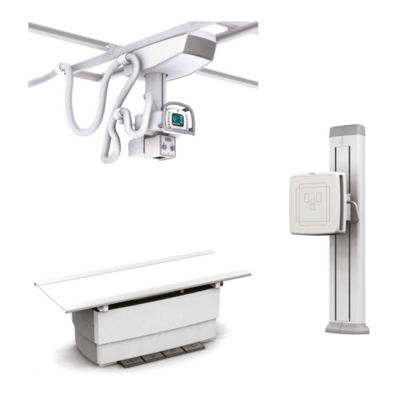
DX-D 600 User Manual SYSTEM CONFIGURATION Illustration 1-1 DX-D 600 X-ray Systems Double Panel Single Panel DX-D 600 SYSTEMS OMPONENTS EMI-AUTOMATIC UTOMATIC Ceiling Suspension Control Console Touchscreen Control Console Touchscreen Control Console Ralco R225DHHS Manual Collimator Collimator Ralco R225ACS Automatic Collimator... - Page 11 DX-D 600 User Manual DX-D 600 SYSTEMS OMPONENTS EMI-AUTOMATIC UTOMATIC RAD Table Fixed DR Detector Fixed DR Detector Receptor & & Portable DR Detector Portable DR Detector Sensing Tray Grid 132 Lines, 10:1, FFD 1 m 132 Lines, 10:1, FFD 1 m...
-
Page 12: General Features
DX-D 600 User Manual GENERAL FEATURES The main features of the X-ray System are: Ergonomic, robust and light weight design, to withstand intensive hospital use. Easy operation, security and precision of all positioning movements with respect to patient. - Page 13 DX-D 600 User Manual Illustration 1-2 DX-D 600 Ceiling Suspension Beside the mentioned features, the differences between both models are: SEMI-AUTOMATIC CEILING SUSPENSION Fully manual positioning in all axis with Vertical Axis motorized for automatic movement. Auto-positioning, Auto-tracking and Auto-centering in Vertical Axis.
-
Page 14: Rad Table
DX-D 600 User Manual 1.3.2 RAD TABLE Illustration 1-3 DX-D 600 RAD Table Smooth and extra optimized elevating mechanism for outstanding patient comfort with a large vertical travel. Foot pedal control for RAD Table movements. Four way floating Tabletop. -
Page 15: Rad Wall Stand Dr
DX-D 600 User Manual 1.3.3 RAD WALL STAND DR Illustration 1-4 DX-D 600 RAD Wall Stand DR Manual and motorized vertical motion balanced with internal counterweights. DR Detector (max. 430 x 430 mm). Manual Tilting which provides DR Detector angulation from +90 ... -
Page 16: X-Ray Generator
DX-D 600 User Manual 1.3.4 X-RAY GENERATOR Illustration 1-5 DX-D 600 X-ray Generator The Generator Cabinet comprises the Power Module, which contains the power and control components and the High Voltage Transformer. The Generator is controlled by multiple microprocessors providing ... -
Page 17: Product Identification
DX-D 600 User Manual PRODUCT IDENTIFICATION The major items in the equipment have some identification labels attached to them which provide the following manufacturer and product information. Product Model Volts (V), Line Phases, Frequency (Hz), and Power (kVA, kW) ... -
Page 18: Indications For Use
Examinations can be performed to any kind of patient group. Patients may be physically abled, disabled, immobilized or in a state of shock. The DX-D 600 X-ray System contributes to the metrics of imaging performance ensuring the efficient use of radiation. -
Page 19: Applied Parts
DX-D 600 User Manual APPLIED PARTS Applied Parts refer to parts of the medical equipments that in Normal Use necessarily comes into physical contact with the patient for the medical equipment to perform its function. These equipments include the following... - Page 20 DX-D 600 User Manual This page intentionally left blank. 0242F EN 20181218...
-
Page 21: Safety And Regulatory Information
DX-D 600 User Manual SECTION 2 SAFETY AND REGULATORY INFORMATION This section describes the safety considerations, general precautions for patient, operator and equipment in order to perform a safe operation and service tasks. Regulatory information and symbols used in the equipment are detailed in this section to operate it safely. - Page 22 DX-D 600 User Manual OPERATOR AND SERVICE PERSONNEL AUTHORIZED TO USE, INSTALL, CALIBRATE MAINTAIN THIS EQUIPMENT MUST BE AWARE OF THE DANGER OF EXCESSIVE EXPOSURE TO X-RAY RADIATION. IT IS VITALLY IMPORTANT THAT EVERYONE WORKING WITH X-RAY RADIATION IS PROPERLY TRAINED, INFORMED ON THE HAZARDS OF RADIATION AND TAKE ADEQUATE STEPS TO ENSURE PROTECTION AGAINST INJURY.
- Page 23 DX-D 600 User Manual SPECIAL ATTENTION MUST BE GIVEN TO DIAGNOSTIC X-RAY EQUIPMENT SPECIFIED USED COMBINATION WITH ACCESSORIES OR OTHER ITEMS. BE AWARE OF POSSIBLE ADVERSE EFFECT ARISING FROM THESE MATERIALS LOCATED IN THE X- -RAY BEAM. (SEE THE TABLE BELOW FOR THE MAXIMUM EQUIVALENT ATTENUATION OF MATERIALS POSSIBLY LOCATED IN THE X-RAY BEAM).
-
Page 24: Responsibilities
DX-D 600 User Manual RESPONSIBILITIES THIS X-RAY UNIT MAY BE DANGEROUS TO PATIENT AND OPERATOR UNLESS SAFE EXPOSURE FACTORS, OPERATING INSTRUCTIONS MAINTENANCE SCHEDULES ARE OBSERVED. THE EQUIPMENT HEREIN DESCRIBED IS SOLD WITH THE UNDERSTANDING THAT MANUFACTURER, AGENTS, AND REPRESENTATIVES ARE NOT LIABLE FOR... -
Page 25: Maximum Permissible Dose (Mpd)
DX-D 600 User Manual IT IS THE RESPONSIBILITY OF THE PURCHASER / CUSTOMER TO PROVIDE THE MEANS FOR AUDIO AND VISUAL COMMUNICATION BETWEEN THE OPERATOR AND THE PATIENT. IT IS THE RESPONSIBILITY OF THE OPERATOR TO ENSURE THAT ALL THE EXPOSURE PARAMETERS ARE CORRECT... -
Page 26: Radiation Protection
DX-D 600 User Manual RADIATION PROTECTION Although this equipment is built to the highest safety standards and incorporates a high degree of protection against X-radiation other than the useful beam, no practical design of equipment can provide complete protection, nor can any practical design compel the operator to take adequate precautions to prevent the possibility of any persons carelessly, unwisely, or unknowingly exposing themselves or others to X-radiation. - Page 27 DX-D 600 User Manual Observe the following rules for radiation protection of the personnel in the examination room during X-ray exposures: - Wear radiation protective clothing. - Wear a personal dosemeter. - Use the different recommended protective materials and devices against radiation.
-
Page 28: Monitoring Of Personnel
DX-D 600 User Manual MONITORING OF PERSONNEL Monitoring of personnel to determine the amount of radiation to which they have been exposed provides a valuable cross check to determine whether or not safety measures are adequate. It may reveal inadequate or improper radiation protection practices and potentially serious radiation exposure situations. - Page 29 DX-D 600 User Manual General Mandatory action. Type B applied part. Protection against harmful ingress of water or particulate matter. IP Classification: Ordinary. Ionizing radiation. Non-ionizing electromagnetic radiation. Radiation of Laser apparatus. Do not stare into beam. (Only applicable to equipment with Laser Pointer) Dangerous voltage.
- Page 30 DX-D 600 User Manual Warning: Non-ionizing radiation. Warning: Laser beam. Warning: Dangerous voltage. Warning: Do not place fingers between mobile and fixed parts of the equipment, it may cause serious injuries to patient or operator. As well, make sure the patient extremities are correctly positioned into limit areas during operation, movement of parts may cause serious damages to patient.
- Page 31 DX-D 600 User Manual Stop (of action). Emergency stop. “ON” power. “OFF” power. “ON” / “OFF” (push-push). Each position, “ON” or “OFF”, is a stable position. Alternating current. Three-phase alternating current. Three-phase alternating current with neutral conductor. Connection point for the neutral conductor on Permanently Installed equipment.
- Page 32 DX-D 600 User Manual Direct current. Both direct and alternating current. Protective Earth (Ground). Earth (Ground). This symbol according to the European Directive indicates that the Waste of Electrical and Electronic Equipment (WEEE) must not be disposed of as unsorted municipal waste and must be collected separately.
-
Page 33: Regulatory
User Manual REGULATORY 2.7.1 CERTIFICATIONS The DX-D 600 Radiographic Room covered by this Operation Manual is authorized to be marked with CE MARKING in accordance with the provisions of the Council Directive 93/42/EEC as amended by 2007/47/EC concerning Medical Devices. -
Page 34: Protection Against Electric Shock Hazards
DX-D 600 User Manual 2.7.4 PROTECTION AGAINST ELECTRIC SHOCK HAZARDS Protection against electric shock hazards in accordance with Standards: IEC 60601-1:1988, 2005 2012, IEC 60601-2-7:1998, 60601-2-54:2009 and 2015. This equipment has been classified as a type-B ( ) device, in accordance with Standard IEC 60601-1 requirements. -
Page 35: Designated Significant Zones Of Occupancy
DX-D 600 User Manual 2.7.8 DESIGNATED SIGNIFICANT ZONES OF OCCUPANCY X-ray equipment specified for examination that do not need the operator or staff to be close to the patient during normal use shall be provided with means to allow the following control functions from a “Protected Area” (refer to illustration below): Selection and control of modes of operation. - Page 36 DX-D 600 User Manual X-Ray equipment specified for any radiological examination that requires the operator or staff to be close to the patient during normal use (e.g., some pediatric examinations or other types of examination for patients that may require assistance), shall have at least one “Significant Zone of Occupancy” for...
- Page 37 DX-D 600 User Manual Illustration 2-2 Radiographic Examination on the RAD Table X-ray Tube Focal Spot Phantom X- -Ray Receptor Patient Support RAD Table S = SIGNIFICANT ZONE OF OCCUPANCY MINIMUM AREA 60 x 60 cm MINIMUM HEIGHT ABOVE THE FLOOR 200 cm...
-
Page 38: Distribution Of Stray Radiation
DX-D 600 User Manual 2.7.9 DISTRIBUTION OF STRAY RADIATION Measurements conditions to determine the distribution of Stray Radiation in the Significant Zone of Occupancy are in accordance with Standard IEC60601-1-3:1994, 2008 and 2013: Exposure Parameters RAD mode: 150 kVp, 10 mAs, 50 mA. - Page 39 DX-D 600 User Manual Illustration 2-3 Distribution of Stray Radiation with the Receptor in Vertical Left Position (S1) 10000 20000 30000 40000 STRAY RADIATION (μGy/h) S1 SID 50 cm S1 SID 100 cm SIGNIFICANT ZONE OF OCCUPANCY ON THE LEFT SIDE OF THE RAD WALL...
- Page 40 DX-D 600 User Manual Illustration 2-4 Distribution of Stray Radiation with the Receptor in Vertical Right Position (S2) 10000 20000 30000 40000 STRAY RADIATION (μGy/h) S2 SID 50 cm S2 SID 100 cm SIGNIFICANT ZONE OF OCCUPANCY ON THE RIGHT SIDE OF THE RAD...
- Page 41 DX-D 600 User Manual Illustration 2-5 Distribution of Stray Radiation within the Receptor in Horizontal Front Side Position (S3) 10000 20000 30000 40000 STRAY RADIATION (μGy/h)) S3 SID 50 cm S3 SID 100 cm RAD TABLE Focal Spot X-ray Tube...
- Page 42 DX-D 600 User Manual Illustration 2-6 Distribution of Stray Radiation with the Receptor in Horizontal Left Side Position (S4) 10000 20000 30000 40000 STRAY RADIATION (μGy/h) S4 SID 50 cm S4 SID 100 cm RAD TABLE Focal Spot X-ray Tube...
- Page 43 DX-D 600 User Manual Illustration 2-7 Distribution of Stray Radiation with the Receptor in Horizontal Right Side Position (S5) 10000 20000 30000 40000 STRAY RADIATION (μGy/h) S5 SID 50 cm S5 SID 100 cm RAD TABLE Focal Spot X-ray Tube...
- Page 44 DX-D 600 User Manual Illustration 2-8 Distribution of Stray Radiation with the Receptor in Horizontal Back Side Position (S6) 10000 20000 30000 40000 50000 60000 STRAY RADIATION (μGy/h) S6 SID 50 cm S6 SID 100 cm RAD TABLE Focal Spot...
-
Page 45: Electromagnetic Compatibility (Emc)
DX-D 600 User Manual ELECTROMAGNETIC COMPATIBILITY (EMC) This equipment generates, uses, and can radiate radio frequency energy. The equipment may cause radio frequency interference to other medical or non medical devices and to radio communications. To provide reasonable protection against such interference, this equipment complies with emissions limits for a Group 1 -- Class A Medical Devices Directive as stated in IEC 60601-1-2: 2007 and 2014. - Page 46 (IEC 60601-1-2:2007 AND IEC 60601-1-2:2014) The DX-D 600 Radiographic Room is intended for use in the electromagnetic environment specified below. The customer or the user of the DX-D 600 Radiographic Room should assure that it is used in such an environment. Emissions test...
- Page 47 (IEC 60601-1-2:2007) The DX-D 600 Radiographic Room is intended for use in the electromagnetic environment specified below. The customer or Operator of the DX-D 600 Radiographic Room should assure that it is used in such an environment. IEC 60601-1-2:2007 Electromagnetic...
- Page 48 (IEC 60601-1-2:2007) This DX-D 600 Radiographic Room is intended for use in an electromagnetic environment specified below. The customer or Operator of this DX-D 600 Radiographic Room should assure that it is used in such an environment. IEC 60601-1-2:2007 Immunity test...
- Page 49 AND MOBILE RF COMMUNICATIONS EQUIPMENT AND THE X-RAY SYSTEM (IEC 60601-1-2:2007) This DX-D 600 Radiographic Room is intended for use in an electromagnetic environment in which radiated RF disturbances are controlled. The customer or the user of this DX-D 600 Radiographic Room can help prevent electromagnetic interference by maintaining a minimum distance between portable and mobile RF communications equipment (transmitters) and the DX-D 600 Radiographic Room as recommended below, according to the maximum output power of the communications equipment.
- Page 50 DX-D 600 User Manual GUIDANCE AND MANUFACTURER’S DECLARATION - ELECTROMAGNETIC IMMUNITY (IEC 60601-1-2:2014) This X-ray System is intended for use in the electromagnetic environment specified below. The customer or Operator of this X-ray System should assure that it is used in such an environment.
- Page 51 DX-D 600 User Manual GUIDANCE AND MANUFACTURER’S DECLARATION - ELECTROMAGNETIC IMMUNITY (IEC 60601-1-2:2014) This X-ray System is intended for use in an electromagnetic environment specified below. The customer or Operator of this X-ray System should assure that it is used in such an environment.
- Page 52 DX-D 600 User Manual IMMUNITY REQUIREMENTS TO RF WIRELESS COMMUNICATIONS EQUIPMENT (IEC 60601-1-2:2014) This X-ray System is intended for use in an electromagnetic environment specified below. The customer or Operator of this X-ray System should assure that it is used in such an environment.
- Page 53 DX-D 600 User Manual QUANTITATIVE INFORMATION The following tables show the Quantitative Information associated Note to this X-ray System according with the Standard IEC 60601- -1- -3:2008 and IEC 60601- -1- -3:2008/AMD1:2013. These tables illustrate loading factors for image performance and supply Dose indication examples.
- Page 54 DX-D 600 User Manual Quantitative Information Loading Factors Parameter Selection Filtrat. Measured Doses 0.012 Small 0.016 0.025 7.479 10.795 0.036 Small 0.087 0.136 4.906 7.682 0.213 13 13 13x13 Large 0.836 1.307 9.407 14.125 1.962 Large 3.073 4.802 17.286 23.863 6.629...
- Page 55 DX-D 600 User Manual Quantitative Information Loading Factors Parameter Selection Filtrat. Measured Doses 0.012 Small 0.046 0.072 21.746 113.713 0.379 Small 0.252 0.394 14.195 79.388 2.205 13 13 13x13 Large 39.4 2.587 4.042 29.103 157.649 21.896 Large 191.4 10.009 15.639 56.299...
- Page 56 DX-D 600 User Manual Quantitative Information Loading Factors Parameter Selection Filtrat. Measured Doses 0.012 Small 0.087 0.136 40.753 378.000 1.260 Small 0.461 0.702 25.909 256.070 7.113 13 13 13x13 Large 74.5 4.674 7.303 52.582 511.763 71.078 Large 366.7 18.374 28.709 103.353...
- Page 57 DX-D 600 User Manual Quantitative Information Loading Factors Parameter Selection Filtrat. Measured Doses 0.012 Small 0.131 0.205 61.550 854.348 2.848 Large 11.2 0.698 1.091 39.282 562.852 15.635 13 13 13x13 Large 7.136 11.149 80.276 1132.591 157.304 Large 448.9 28.400 44.375 127.800...
- Page 58 DX-D 600 User Manual Quantitative Information Loading Factors Parameter Selection Filtrat. Measured Doses 0.012 Small 0.194 0.303 90.897 1611.652 5.372 Large 19.1 1.037 1.620 58.304 7.682 0.213 13 13 13x13 Large 164.1 10.722 16.753 120.620 2195.061 304.870 Large 823.7 43.078 67.310...
- Page 59 DX-D 600 User Manual Quantitative Information Loading Factors Parameter Selection Filtrat. Measured Doses 0.012 Small 0.253 0.395 118.573 2493.391 8.311 Large 24.4 1.375 2.148 77.331 1679.791 46.661 13 13 13x13 Large 239.3 14.530 22.704 163.467 3508.591 487.304 Large 882.9 59.548 93.043...
- Page 60 Agfa. If the device malfunctions and may have caused or contributed to a serious injury of a patient, Agfa must be notified immediately by telephone, fax or written correspondence to the following address: AGFA Service Support - local support addresses and phone numbers are listed on www.agfa.com...
- Page 61 DX-D 600 User Manual SECTION 3 STARTUP AND SHUTDOWN START UP The System should be powered by the same Room Electrical Cabinet where the X-ray Generator is connected, that is, the whole System will be powered from the same Electrical Cabinet.
- Page 62 DX-D 600 User Manual The Ceiling Suspension and the RAD Table are provided also with an Emergency OFF Switch that cuts the power supply to the Unit. Once pressed, wait almost one minute before turning ON the Unit again. IN THE EVENT OF AN EMERGENCY FORCIBLY DEPRESS THE “EMERGENCY OFF SWITCHES”...
- Page 63 DX-D 600 User Manual THE CEILING SUSPENSION CAN MOVE FREELY ALONG THE LONGITUDINAL AND TRANSVERSE AXIS WHEN MINIMAL FORCE IS APPLIED. THE CEILING SUSPENSION MOVEMENT WILL STABILIZE AT THE CENTER POSITION. THE TABLETOP CAN MOVE FREELY IN LONGITUDINAL AND TRANSVERSE DIRECTION WHEN MINIMAL FORCE IS APPLIED.
- Page 64 DX-D 600 User Manual This page intentionally left blank. 0242F EN 20181218...
- Page 65 DX-D 600 User Manual SECTION 4 CEILING SUSPENSION OPERATION Illustration 4-1 Ceiling Suspension Nomenclature Longitudinal Rails Transverse Rails Carriage Telescopic Column Emergency-OFF Switch (Automatic Model) Hose Control Console L-block Collimator RAIL SYSTEM The Rail System is formed by two pairs of rails made of aluminum and available in different lengths (refer to Section 1.2).
- Page 66 DX-D 600 User Manual Illustration 4-2 Ceiling Suspension Axis and Travels ¦135 X-ray Tube Angulation in Alpha Axis ¦180 X-ray Tube Angulation in Beta Axis CARRIAGE The Carriage contains some electronics and mechanics components of the Ceiling Suspension and supports the Telescopic Column, L-Block Assembly, X-ray Tube Support with the Tube, Collimator and Control Console.
- Page 67 DX-D 600 User Manual L-BLOCK ASSEMBLY This assembly is the junction between the Telescopic Column and the X-ray Tube and Collimator Assembly. It contains electronic and the mechanical components to allow the movement of the X-ray Tube in the Alpha Axis (Angulation) and Beta Axis (Rotation).
- Page 68 DX-D 600 User Manual CONTROL CONSOLE The Control Console enables the operator to control the movements (manual and/or motorized) of the Ceiling Suspension and also the automatic movements of the System (Auto-tracking, Auto-positioning, Auto-centering.) Brakes Buttons are used to control each axis brake/movement. When a button is pressed and held, the brake is released, so the equipment can be moved in the free axis.
- Page 69 DX-D 600 User Manual TOUCHSCREEN CONTROL CONSOLE Both Automatic and Semi-automatic Ceiling Suspension models are provided with the Touchscreen Control Console and a Graphical User Interface (GUI) that allow the operator to configure the Exposure Technique, Workstation, X-Ray Tube and DR Detectors position.
- Page 70 DX-D 600 User Manual The Touchscreen interface is composed by the next data areas: PATIENT INFORMATION. Patient Name is displayed. COLLIMATOR. Mode and configuration of the collimation indicator. MOVEMENTS & WORKSTATIONS. Select the Workstation and activate/deactivate the automatic movements.
- Page 71 DX-D 600 User Manual Press on Configuration Areas buttons to access to them. INFO check exposition configuration: Patient data, Collimation and APR configuration, X-ray Tube position, Technique and AEC configuration. POSITION configure the X-ray Tube position. RAD for Technique configuration and modification.
- Page 72 DX-D 600 User Manual 4.1.2 MOVEMENTS CONTROLS AND INDICATORS AUTO-CENTER. Get active the Auto-center function to align the X-ray Tube with the DR Detector. RAD Table or RAD Wall Stand Workstations must be selected. It is not active for Direct Workstation.
- Page 73 DX-D 600 User Manual 4.1.4 INFO AREA INFO appears just after the Ceiling Suspension has been switched ON. In this display it is possible to check: Configured exposure. X-ray Tube Position: ANG or X-ray Tube angle ROT or X-ray Tube rotation angle...
- Page 74 DX-D 600 User Manual Illustration 4-8 Tube Position Description and Vertical DR Detector Tilting -135 -180 TILT 0242F EN 20181218...
- Page 75 DX-D 600 User Manual 4.1.5 RAD AREA Select for Technique configuration: AEC. It is possible to select any combination of AEC area. Selected option is highlighted by the shaded background. It is possible that the AEC were not available by configuration or if the Direct Workstation is selected.
- Page 76 DX-D 600 User Manual CEILING SUSPENSION MOVEMENTS MONITOR THE EQUIPMENT MOVEMENTS WITH SPECIAL CARE. AVOID ANY IMPACT OF THE SYSTEM ON FLOOR, WALLS, OR OTHER ELEMENTS IN THE ROOM. IT MAY CAUSE SERIOUS DAMAGE TO THE EQUIPMENT. MONITOR WITH SPECIAL CARE THE PATIENT POSITION (HANDS, FEET, FINGERS, ETC.) TO AVOID INJURY TO...
- Page 77 DX-D 600 User Manual BEFORE POWERING ON AND MOVE THE UNIT, CHECK THAT THERE IS NO OBJECT OR OBSTACLE ON THE TUBE SUPPORT OR THE L-BLOCK SURFACE FOR THE CORRECT MOTION OF THE SUSPENSION. THIS EQUIPMENT CAN BE MOVED IN DIFFERENT AXES.
- Page 78 DX-D 600 User Manual 4.2.2 DETENT POINTS Detent Points are defined work positions where locks are activated once the Ceiling Suspension reaches at one of these positions. When stopped at one of these Detent Points, in order to continue with the movement, just released the brake by pushing its corresponding button and move manually or perform another auto-position.
- Page 79 DX-D 600 User Manual There are different kind of Detents Points: Floating and Electronic Detent Points. Both systems are provided with floating Detent Points by default. These points are defined by software in every final position of a PP or Auto-position: In case of the Automatic System refer to Section 4.2.4 - “Position.
- Page 80 DX-D 600 User Manual 4.2.3 AUTOMATIC MOVEMENTS There are three types of motorized/automatic movements: Auto-center, Auto-tracking and Auto-positioning. The Automatic Ceiling Suspension has motorized motion in all Note axes, but the Semi-automatic Ceiling Suspension is motorized only in Vertical Axis. So, all automatic movements are available just in the Vertical Axis.
- Page 81 User Manual 4.2.3.2 REMOTE CONTROL The Remote Control is an option just for DX-D 600 Automatic Systems. The Remote Control allows: to control the Automatic Collimator blades aperture and light, to move vertically the DR Detector of the RAD Wall Stand DR,...
- Page 82 DX-D 600 User Manual To use the Remote Control: Point the Remote Control to the Ceiling Suspension Carriage, where the IR Detector is located. Illustration 4-14 Ceiling Suspension IR Detector Hold pressed the desired movement button to move the equipment.
- Page 83 DX-D 600 User Manual The Remote Control Functions are: Collimator LONGITUDINAL FIELD SIZE Adjustment: Press the top of the button to close the Collimator Press the bottom to open the Collimator. Collimator LIGHT SWITCH. Turn the collimator light ON / OFF.
- Page 84 DX-D 600 User Manual X-Ray Tube Angulation Hold pressed the left button to move the tube from 0 to -135 Hold pressed the right button to move the tube from 0 to 135 -135 Vertical displacement of the X-ray Tube...
- Page 85 DX-D 600 User Manual The Remote Control Device is powered by an alkaline Nine-volt Battery (transistor battery type). For its replacement: Remove the Battery cover. Remove the Battery from the snap connector. Replace old battery with the new one. Insert and fix the cover.
- Page 86 4.2.3.3 EMERGENCY STOP FOR AUTOMATIC MOVEMENTS The DX-D 600 is equipped with different Emergency OFF Switches placed at top of the X-ray Tube Covers in the Ceiling Suspension (just for Automatic Systems), in the RAD Table, in the Automatic Positioning Control Box and in the Electrical Room Cabinet.
- Page 87 DX-D 600 User Manual Volumetric protection areas are activated around both DR Detectors. A virtual safety area has to be configured around a patient lied down on the RAD Table or positioned at the RAD Wall Stand DR. Illustration 4-17 Patient Virtual Safety Areas 100 mm (4”)
- Page 88 DX-D 600 User Manual 4.2.3.5 X-RAY INTERLOCK The X-ray INTERLOCK Indicator appears at the bottom of the Console on the Ceiling Suspension Status Area. Once the interlock is activated it is not possible to make any exposure, press on the Indicator to get information about the causes of the Interlock.
- Page 89 DX-D 600 User Manual 4.2.3.6 AUTO-CENTER The Ceiling Suspension gets aligned the X-ray Tube with the center of the DR Detectors of the RAD Table or RAD Wall Stand, it is not active with the Direct Workstation. DUE TO SAFETY REASONS, THE MINIMUM SID FOR AUTO-CENTER FUNCTION IS HELD AT 950 mm (37.4”) FROM...
- Page 90 DX-D 600 User Manual If the Semi-Automatic Ceiling Suspension is not in the correct position in non motorized axes (Longitudinal, Transverse, Alpha or Beta), a message will be displayed explaining the corrective action to be completed. It is indicated first the Current Position and the Final Position too.
- Page 91 DX-D 600 User Manual 4.2.3.7 AUTO-TRACKING This function allows the X-ray Tube to follow the DR Detector when it changes its position or the other way around. By default, in most of the cases the SID is constant. Master refers to the equipment which initiates the movement and Slave to the equipment which tracks the Master movement.
- Page 92 DX-D 600 User Manual To activate the Auto-tracking function, the SID must be between 950 mm (37.4”) and <4000 mm (137.5”), if Room configuration and rails dimensions allow it. Once the Auto-tracking function is activated, the current SID is the default one during the automatic movement.
- Page 93 DX-D 600 User Manual AUTOMATIC CEILING SUSPENSION WITH RAD TABLE Depending on the Axis: Horizontal Auto-tracking. Both pieces of equipment can operate as Master or Slave. Vertical Auto-tracking. The RAD Table is always the Master element and the Ceiling Suspension the Slave.
- Page 94 DX-D 600 User Manual Illustration 4-23 Auto-tracking Movement Policy for Automatic System with RAD Table Master Slave Slave Master Slave Slave Master Master Slave Slave Master Master Slave Master Raise Lower Slave Slave Master Master 0242F EN 20181218...
- Page 95 DX-D 600 User Manual AUTOMATIC CEILING SUSPENSION WITH RAD WALL STAND DR Depending on the DR Detector tilting angle: The Receptor can be the Master in all cases, even when it is tilted. The Suspension can move UP/DOWN or in Alpha Axis to get the X-ray tube aligned.
- Page 96 DX-D 600 User Manual Illustration 4-24 Auto-tracking Movement Policy for Automatic System with RAD Wall Stand DR Master Master Slave Slave Slave Slave Master Master Slave Master 0242F EN 20181218...
- Page 97 DX-D 600 User Manual SEMI-AUTOMATIC CEILING SUSPENSION WITH RAD TABLE In Semi-automatic Systems the Auto-tracking movement is available only in the Vertical direction, by default. The DR Detector of the Semi-automatic Table is not motorized, so Note it cannot be controlled and tracked longitudinally by the Ceiling Suspension.
- Page 98 DX-D 600 User Manual Illustration 4-25 Auto-tracking Movement Policy for Semi-automatic System with RAD Table Slave Master Raise Lower Slave Slave Master Master 0242F EN 20181218...
- Page 99 DX-D 600 User Manual SEMI-AUTOMATIC CEILING SUSPENSION WITH RAD WALL STAND DR Both the DR Detector and the Ceiling Suspension can be Master and Slave, but the Auto-tracking movement is always in vertical direction. Proceed as indicated for manually operated Auto-tracking:...
- Page 100 DX-D 600 User Manual Illustration 4-26 Auto-tracking Movement PolIcy for Semi-automatic System with RAD Wall Stand DR Slave Slave Slave Master Master Master Master Slave 0242F EN 20181218...
- Page 101 DX-D 600 User Manual HOW TO DEACTIVATE THE AUTO-TRACKING FUNCTION Press the AUTO-TRACKING control of the Console or Remote Control, if available, press any brake button of the Control Console, press any button that implies misalignment between the DR Detector and ...
- Page 102 DX-D 600 User Manual 4.2.4 POSITION. AUTOMATIC SYSTEM AUTO-POSITIONING Configure directly in the Position screen of the Control Console the X-ray Tube position manually or using any Auto-position. Up to 16 Auto-position can be programmed in the field, each one refers to configured parking positions of the X-ray Tube (SID, ANG &...
- Page 103 DX-D 600 User Manual MANUAL POSITION Select the Workstation. Use the INCREASE/DECREASE Buttons to modify the Position Parameters. Which are: SID: Source-Image Distance from 800 to 2000 mm (31.5” to 78.7”). ANG: X-ray Tube angle degrees on Alpha Axis from -90 to 90...
- Page 104 DX-D 600 User Manual 4.2.5 POSITION. SEMI-AUTOMATIC SYSTEM AUTO-POSITIONING As the Semi-automatic Ceiling Suspension is NOT motorized in all axes, the Auto-positioning function is possible only in the Vertical Axis. Therefore, this feature operation is different to the described for the Automatic Ceiling Suspension.
- Page 105 DX-D 600 User Manual In case the Auto-position involves any movement in the Longitudinal, Transverse, Alpha and Beta Axes, it must be completed manually before executing the Auto-position. Press the Auto-center Indicator, a message will be displayed in the console explaining the corrective action to be completed.
- Page 106 DX-D 600 User Manual 4.2.6 PROGRAMMED POSITIONS (PP) Each PP refers to a position of the X-ray Tube (SID, ANG & ROT), but also to the DR Detector of the RAD Table on vertical and longitudinal travels, and to the DR Detector of the RAD Wall Stand on vertical travel and on tilting angle.
- Page 107 DX-D 600 User Manual Select Programmed Positions (PP), Buttons. parameters values, INCREASE/DECREASE Description and ID Number are displayed. In case the Programmed Position (PP) involves any movement in the Longitudinal, Transverse, Alpha and Beta Axes, it must be completed manually before executing the Auto-position. Press the AUTO-CENTER Indicator of the Control Console, a message will be displayed in the console explaining the corrective action to be completed.
- Page 108 DX-D 600 User Manual X-RAY BEAM ALIGNMENT WITH RESPECT TO PATIENT After selecting RAD parameters for the technique to be performed: Point the X-Ray Tube-Collimator Assembly to the Image Receptor (refer to Illustration 4-32.) Center the Collimator light, which corresponds to the X-Ray beam, with respect to the receptor.
- Page 109 DX-D 600 User Manual Illustration 4-32 Patient Positioning In Double Panel Systems Collimator Knobs X-Ray Beam Laser Line Collimator Light Collimator Knobs Laser Line X-Ray Beam Collimator Light 0242F EN 20181218...
- Page 110 DX-D 600 User Manual This page intentionally left blank. 0242F EN 20181218...
- Page 111 DX-D 600 User Manual SECTION 5 RAD TABLE OPERATION The RAD Table is mandatory for Double Panel System Room Note Configuration, but it is not present in Single Panel Systems, where the RAD Wall Stand DR tilting is used when it is required to complete examinations with the DR Detector in horizontal position.
- Page 112 DX-D 600 User Manual TABLETOP The Patient Support can be longitudinally and transversely moved, allowing an easy patient positioning. It can be also raised up to a maximum height of 920 mm (36.22”) and lowered to a minimum height of 580 mm (22.83”). There are three different tabletop models available: Standard Tabletop, which is the default option.
- Page 113 DX-D 600 User Manual DR DETECTOR ASSEMBLY It includes the DR Detector, Container Box and Handle Button. The DR Detector can be fixed or portable. ACTIVE WORKSTATION INDICATOR When the RAD Table is selected as the current active Workstation on the System, the Active Workstation Indicator gets blue lighted.
- Page 114 DX-D 600 User Manual PATIENT POSITIONING DURING PATIENT POSITIONING, MAKE SURE THAT PATIENT HEAD, HANDS AND FEET ARE COMPLETELY INSIDE THE TABLETOP AREA. SERIOUS INJURIES OR DAMAGES CAN BE CAUSED IF ANY PART IS OUTSIDE THIS AREA. Proceed always to position the patient in accordance to the next safety rules: The Tabletop supports an evenly distributed maximum load of 300 kg ...
- Page 115 DX-D 600 User Manual TABLETOP MOVEMENTS The Tabletop can be raised, lowered and four way moved by pressing the corresponding Control Pedal. Illustration 5-3 Tabletop travels and Control Pedals Emergency OFF Switch DR Detector Assembly Tabletop Motion Raise Lower Tabletop Motion Active Workstation Indicator 5.2.1...
- Page 116 DX-D 600 User Manual DURING TABLETOP MOVEMENT, BE SURE THAT PATIENT HEAD, HANDS AND FEET ARE COMPLETELY WITHIN THE TABLETOP AREA. IF ANY PART OF THE PATIENT IS OUT OF THE TABLETOP AREA, DAMAGES AND INJURIES CAN BE PROVOKED TO THE PATIENT. WATCH THE TABLETOP MOVEMENTS TO AVOID DAMAGES AND INJURIES.
- Page 117 DX-D 600 User Manual TABLETOP ALSO MOVE FREELY LONGITUDINAL AND TRANSVERSE AXES WHEN MINIMAL FORCE IS APPLIED. IF THE PATIENT IS STILL ON THE TABLE, HE MAY NEED HELP TO STEP DOWN FROM THE RAD TABLE. DO NOT TRY TO MOVE THE TABLETOP LONGITUDINALLY NOR TRANSVERSELY WITHOUT PRESSING THE CONTROL PEDAL.
- Page 118 DX-D 600 User Manual THE TABLETOP MUST BE PREVIOUSLY CENTERED AND WITH THE PATIENT COMPULSORILY LIED DOWN FOR A SAFE VERTICAL MOVEMENT. THE RAD TABLE PROVIDES A SAFETY SYSTEM WHICH STOPS THE VERTICAL MOVEMENT WHEN THE TABLETOP TRAVEL FINDS AN OBSTACLE.
- Page 119 DX-D 600 User Manual PORTABLE DR DETECTOR LOADING Using the DR Detector Handle, pull out the Tray to insert the DR Detector. Press and hold the Handle brake until the Tray is completely pulled out. Insert the Detector to the back of the Tray. Push slightly the back end-stops with the Detector for a correct fixation and fit it with the front end-stops.
- Page 120 DX-D 600 User Manual Pull out the Grid Tray. Install the Grid with the tube side label facing up. Push in the Grid Tray. Check that the Grid is correctly inserted in the slot. A click sound means that the Grid is in place.
- Page 121 DX-D 600 User Manual 5.6.2 COMPRESSION BAND This device supplies compression to the anatomical area of interest in order to avoid unnecessary movements. It is mounted on the Tabletop rails. Fit totally both brackets of the Compression Band to the rails and use the lever lock or unlock the Compression Band to get the required extension of the Band.
- Page 122 DX-D 600 User Manual 5.6.4 LATERAL DR DETECTOR (35X43) HOLDER WITH TROLLEY This mobile DR detector holder is designed to acommodate portable DR detectors of 35x43 cm (14”x17”). Illustration 5-8 Mobile Detector Holder Insert the portable DR Detector in the Support. It must be always in landscape orientation.
- Page 123 DX-D 600 User Manual The Holder is adjustable for height, the vertical travel of the DR Detector is 750 mm (29.5”). To move up/down the Support: Loosen CCW the Vertical Lock Lever to free the DR Detector Support. Hold the Support during this procedure to avoid unexpected falls.
- Page 124 DX-D 600 User Manual To move the Holder in order to place it in its working or parking position, proceed as indicated below: Unlock all wheels. Drive the Holder holding the vertical bar and carry it where corresponds. DRIVE THE HOLDER WITH SPECIAL CARE. AVOID ANY...
- Page 125 DX-D 600 User Manual ASSEMBLY PROCEDURE Before its first use, the Holder must be mounted in the field as it is shipped splitted. Refer to the image below for graphical information about its assembly procedure. Tighten the Column to the Trolley.
- Page 126 DX-D 600 User Manual This page intentionally left blank. 0242F EN 20181218...
- Page 127 DX-D 600 User Manual SECTION 6 RAD WALL STAND DR OPERATION Illustration 6-1 RAD Wall Stand DR Components ON/OFF Indicator Overhead Hands Support Wall Mount Bracket Covers Column Carriage Tilting Controls DR Detector Assembly Vertical Brake Handle Front Panel Patient Hands-grips...
- Page 128 DX-D 600 User Manual Covers: They protect the electronics and the mechanics of the Column and give the final appearance to the equipment. Be careful with covers handling to avoid scratches. Counterweights: They allow the counterbalance of the DR Detector ...
- Page 129 DX-D 600 User Manual RAD WALL STAND DR MOVEMENTS The RAD Wall Stand DR enables radiographic operations at different positions within the range of the Vertical Carriage travel, adjustable tilting angles as well as rotation of the DR Detector. MONITOR WITH SPECIAL CARE THE PATIENT POSITION, HANDS, FEET, FINGERS, ETC.) AND USE THE PATIENT...
- Page 130 DX-D 600 User Manual 6.1.2 AUTOMATIC VERTICAL MOVEMENTS This automatic movements are available in automatic RAD Wall Stands DR, provided with motorized vertical motion (refer to Section 1.2 “System Configuration”). 6.1.2.1 DR VERTICAL AUTO-POSITIONING This function is just available in Automatic Ceiling Suspensions, where several Auto-positions and Programmed Positions are configured, so the Receptor movement may be entailed.
- Page 131 DX-D 600 User Manual TILTING NEVER PLACE THE PATIENT’S AND/OR OPERATOR’S HANDS OR FINGERS INSIDE THE TILTING ASSEMBLY AS SHOWN BELOW: IT MAY CAUSE SERIOUS INJURIES TO PATIENT OR OPERATOR. MAKE SURE THAT THE PATIENT EXTREMITIES INSIDE TABLETOP ACCESSORIES LIMITS DURING OPERATION: MOVEMENT OF PARTS MAY CAUSE SERIOUS DAMAGES TO PATIENT.
- Page 132 DX-D 600 User Manual Illustration 6-5 DR Detector Tilting Assembly 90 o Position Lock 0 o Position Lock Tilting Brake Unlock the 0 Detent. Press and hold one of the Tilting Brake pushbuttons located on the DR Detector Support. Tilt manually the DR Detector up to the desired position.
- Page 133 DX-D 600 User Manual DR DETECTOR ROTATION This function allows to rotate the DR Detector around the center of the image, the movement is manually controlled. It is possible to have the DR Detector rotated up to 90 To avoid degradation of image quality and loss of DR Detector...
- Page 134 DX-D 600 User Manual Rotation direction changes depending on the Systems Configuration: For Double Panel Systems or default configuration, rotate always the DR Detector before tilting it. The rotation will be upwards, clockwise for the left load configuration of the DR Detector, or counter-clockwise for the right load.
- Page 135 DX-D 600 User Manual ALIGNMENT The three field pattern on the Front Panel of the RAD Wall Stand corresponds to the three detection areas for the Ion Chamber Detector. It is important that the X-ray Tube is accurately centered with the DR Detector transversely.
- Page 136 DX-D 600 User Manual PORTABLE DR DETECTOR LOADING Using the DR Detector handle pull out the tray to insert the DR Detector. Press and hold the handle brake until the tray is completely pulled out. Insert the DR Detector to the back of the tray. Push slightly the back end-stops with the DR Detector for the correct fixation.
- Page 137 DX-D 600 User Manual GRID LOADING AND REMOVAL Grids are intended to reduce scattered radiation and significantly enhance image quality. The RAD Wall Stand DR holds a removable grid. When inserting the grid in the RAD Wall Stand DR grid slot, pay special attention to the type of focalization distance of each grid.
- Page 138 DX-D 600 User Manual ACCESSORIES The RAD Wall Stand DR is provided with two different models of overhead patient support, both are used for a correct positioning of patients. The patient can hold on to it to separate the arms from the chest, so it is highly recommended for thorax.
- Page 139 DX-D 600 User Manual 6.9.2 MOBILE OVERHEAD PATIENT SUPPORT This optional patient support can tilt down to allow a more ergonomic position of the patient. It is provided with one support (optionally two) installed at the back of the DR Detector, provided with two Locking Pins for its use. It can support a maximum load of 15 kg.
- Page 140 DX-D 600 User Manual The Patient Support can be used in two different positions: Working position, at 0 , and Parking, at +90 or -90 . Pull out the Parking Locking Pin and turn the Support to the opposite of the DR Detector loading configuration.
- Page 141 DX-D 600 User Manual Remember that the Patient Support is installed at the back of the cabinet of the DR Detector, so it is not possible to tilt the DR Detector with it installed. It is necessary to remove it from the Cabinet and then tilt.
- Page 142 DX-D 600 User Manual This page intentionally left blank. 0242F EN 20181218...
- Page 143 DX-D 600 User Manual SECTION 7 COLLIMATION RALCO R225 AUTOMATIC COLLIMATOR Ralco R225 Collimator operation is CanBus controlled by the Note Ceiling Suspension. The Collimator operation with the Ceiling Suspension is described on this Section. Refer to the corresponding Collimator Manual for extended information about operation or technical description needed to maintain compliance with Standard IEC 60601-1-3:2008.
- Page 144 DX-D 600 User Manual After pressing the Collimator Lamp control, the Lamp remains ON for several seconds to allow for patient/grid alignment before turning OFF automatically. An optional Laser positioner may be included with the Collimator Light in order to facilitate patient positioning.
- Page 145 DX-D 600 User Manual 7.1.1 AUTOMATIC MODE The Automatic mode is always activated whenever all the Positive Beam Limitation (PBL) conditions are complied with: The Aperture capacity must be enough to get a Field of View (FOV) according to the std. IEC60601-1-3.
- Page 146 DX-D 600 User Manual 7.1.3 MANUAL MODE To be in manual mode, the reasons are: MESSAGE DESCRIPTION DETECTOR The selected Workstation (DIRECT) does not allow the automatic mode. The Collimator back key is turned. The SID is out of the configured range for the automatic collimation.
- Page 147 DX-D 600 User Manual RALCO MANUAL COLLIMATOR R225/R225 DHHS Collimator controls consist of a button to switch on the Collimator lamp and two knobs to open or close the internal blades of the Collimator. When pressing the Collimator Lamp push-button, the Collimator light and an optional Laser light turn on.
- Page 148 DX-D 600 User Manual DOSIMETER DEVICE (OPTIONAL) The optional Dosimeter device is related to the Collimator installed in the equipment. The usual compatible Dosimeter devices are: Vacudap 2000 / 2004 Series with Manual Collimator Iba Kermax Plus with Automatic Collimator ...
- Page 149 DX-D 600 User Manual SECTION 8 TROUBLESHOOTING GUIDE A guide for a quick solution of main typical problems in the use of this equipment follows. It is recommended to keep this troubleshooting guide with you when operating with the equipment.
- Page 150 DX-D 600 User Manual CEILING SUSPENSION PROBLEM CHECK IF ACTION Emergency Stop Switch is activated. Deactivate Emergency Stop Switch. Check that the Line Power is provided to the CEILING SUSPENSION CAN NOT BE Ceiling Suspension from the Room Electrical SWITCHED ON There is not enough power.
- Page 151 DX-D 600 User Manual 8.4.2 ERROR LIST Following tables list all defined error codes: Error Code. User Error Message. Displayed error message. Error Description: Explains the error and reasons. Action: Suggests the action to be completed in order to correct the error.
- Page 152 DX-D 600 User Manual Table 8-1 (Cont.) System/Miscellaneous CODE USER ERROR MESSAGE ERROR DESCRIPTION ACTION Initial position unreachable Sequence Initial position unreachable Correct and try again Invalid parameter range: Unreachable Sequence Invalid parameter range: Correct and try again positions Unreachable positions...
- Page 153 DX-D 600 User Manual Table 8-2 Ceiling Suspension Motor Controller Boards CODE USER ERROR MESSAGE ERROR DESCRIPTION ACTION Motor Controller Board not connected Check the Motor Controller I/F 11100 Control Board Error: CS-Longitudinal or I2C communication problems Connection Motor Controller Board not connected...
- Page 154 DX-D 600 User Manual Table 8-2 (Cont.) Ceiling Suspension Motor Controller Boards CODE USER ERROR MESSAGE ERROR DESCRIPTION ACTION Axis moved out of defined range manually. Operative rejected: CS-Transversal Axis not calibrated. Check position feedback position out of calibrated range: 11113 Potentiometer misaligned.
- Page 155 DX-D 600 User Manual Table 8-2 (Cont.) Ceiling Suspension Motor Controller Boards CODE USER ERROR MESSAGE ERROR DESCRIPTION ACTION No motor power or motor/driver defective. 11121 Board Failure: CS-Angular Potentiometer/Tachometer or Change board circuitry defective. Coupling did not engage Axis moved out of defined range manually.
- Page 156 DX-D 600 User Manual Table 8-3 Wall Stand Motor Controller Boards CODE USER ERROR MESSAGE ERROR DESCRIPTION ACTION No motor power or motor/driver defective. Control Board Error: 11201 Potentiometer/Tachometer or Replace the Control Driver Board Wall Stand-Vertical circuitry defective. Coupling did not engage No motor power or motor/driver defective.
- Page 157 DX-D 600 User Manual Table 8-3 (Cont.) Wall Stand Motor Controller Boards CODE USER ERROR MESSAGE ERROR DESCRIPTION ACTION Axis moved out of defined range manually. Axis not calibrated. Check End Switch Limit position, End-switch limit: 11212 Potentiometer misaligned. activation, operation.
- Page 158 DX-D 600 User Manual Table 8-4 Table Motor Controller Boards CODE USER ERROR MESSAGE ERROR DESCRIPTION ACTION Control Board Error: Table Replace Control Board 11300 Invalid Calibration Data: 11301 Check Longitudinal Axis calibration Table-Longitudinal Check the Table’s Vertical Axis 11302...
- Page 159 DX-D 600 User Manual Table 8-5 Positioning CODE USER ERROR MESSAGE ERROR DESCRIPTION ACTION 11501 Auto-center forbidden Try again 11502 Auto-tracking forbidden Try again 11503 Parking forbidden Try again 11504 Demand mismatch Try again Operative rejected: SID is out of limits...
- Page 160 DX-D 600 User Manual Table 8-5 (Cont.) Positioning CODE USER ERROR MESSAGE ERROR DESCRIPTION ACTION Operative rejected: System Wait until synchronizing procedure 11521 System synchronizing synchronizing, please wait and try again finishes Operative rejected: System 11522 System synchronizing Wait for system stop...
- Page 161 DX-D 600 User Manual Table 8-6 Safety Messages & Tomography CODE USER ERROR MESSAGE ERROR DESCRIPTION ACTION Tomography: Auto-positioning 11601 movement timeout: Please, check Auto-positioning movement timeout. Please, check positioning parameters positioning parameters Tomography aborted: The Positioner is The Positioner is out of the allowed...
- Page 162 DX-D 600 User Manual Table 8-7 Auto-positioning CODE USER ERROR MESSAGE ERROR DESCRIPTION ACTION Manual mode aborted: Wall Auto-position not completed, 11713 Stand-Vertical timeout: Please, try movement on Wall Stand Vertical Axis Try again again timed out Parking not present in Configuration...
- Page 163 DX-D 600 User Manual Table 8-7 (Cont.) Auto-positioning CODE USER ERROR MESSAGE ERROR DESCRIPTION ACTION Auto-movement aborted: 11762 Configure POSITION CS-Rotation target Manual mode aborted: Auto-position not completed, 11763 CS-Rotational timeout: Please, try movement on Ceiling Suspension Try again again...
- Page 164 DX-D 600 User Manual Table 8-8 Auto-centering CODE USER ERROR MESSAGE ERROR DESCRIPTION ACTION Auto-centering is cancelled because 11801 Auto-movement aborted: CS moved Try again Ceiling Suspension was moved Auto-movement aborted: Wall Stand Auto-centering is cancelled because 11802 Try again...
- Page 165 DX-D 600 User Manual Table 8-8 (Cont.) Auto-centering CODE USER ERROR MESSAGE ERROR DESCRIPTION ACTION Operative rejected: Auto-centering does not start because CS-Angular Target greater than 46 final position for the Ceiling 11851 Move Bucky/Detector and try again limit: Please, check POSITION...
- Page 166 DX-D 600 User Manual Table 8-9 Auto-tracking CODE USER ERROR MESSAGE ERROR DESCRIPTION ACTION Tracking aborted: No Detector 11903 No Bucky/Detector selected Select Bucky/Detector and try again selected Operative rejected: Bucky/Detector and X-ray Tube are 11906 Detector and Tube-crane are...
- Page 167 DX-D 600 User Manual SECTION 9 OPERATING SEQUENCES START-UP ROUTINE Start-up the System as described in Section 3. X-RAY TUBE WARM-UP PROCEDURE Before effecting X-ray exposures ensure that the X-ray Tube is properly warmed-up. Make sure that no people will be inadvertently exposed to unnecessary X-rays during this procedure.
- Page 168 DX-D 600 User Manual RADIOGRAPHIC OPERATION RAD operation can be performed in the following modes: Three point control by selecting kVp, mA and Exposure Time independently. Two point control by selecting kVp and mAs independently. mAs selection sets the maximum mA available for the selected Focal Spot and the respective Exposure Time.
- Page 169 DX-D 600 User Manual When the exposure is finished, release the handswitch button. Repeat the procedure if additional exposures are desired. AEC OPERATION The proper use of AEC requires accurate patient positioning. For examination using AEC, the operator will need to select the desired AEC parameters as follows: Make sure that the X-ray Tube to be used is properly warmed-up.
- Page 170 DX-D 600 User Manual Select “Center” Ion Chamber and Density “Normal - - 0”. Make a RAD exposure and note the exposure mAs and time. For a proper functioning of the AEC, the exposure must not be aborted by the AEC back-up timer.
- Page 171 DX-D 600 User Manual SECTION 10 PERIODIC MAINTENANCE In order to assure a continuous and safe performance of the system, a periodic maintenance program must be established. It is the owner’s responsibility to supply or arrange for this service. There are two levels of maintenance, the first consists of tasks which are performed by the user/operator, and the second are those tasks to be performed by qualified X-ray service personnel.
- Page 172 DX-D 600 User Manual Clean the equipment frequently, particularly if corroding chemicals are present. Clean external covers and surfaces, especially parts in contact with patients, with a cloth moistened in warm water with mild soap. Wipe with a cloth moistened in clean water. Do not use cleaners or solvents of any kind.
- Page 173 DX-D 600 User Manual SECTION 11 TECHNICAL SPECIFICATIONS 11.1 ENVIRONMENTAL REQUIREMENTS ATMOSPHERIC PRESSURE (hPa) RELATIVE HUMIDITY (%) AMBIENT TEMPERATURE WORKING 10 o C (50 o F) 35 o C (95 o F) 700 hPa 1060 hPa TRANSPORT & STORAGE -20 o C (- -4 o F)
- Page 174 DX-D 600 User Manual 11.2.2 INFORMATION RELATED TO RADIATION Radiation Output Accuracy: C.V. (Coefficient of Variation) ≤0.05 (Reproducibility related to loading factors) Maximum Symmetrical Radiation Field: Measured at 75 kVp: 160 mm in “X” axis and 240 mm in “Y” axis.
- Page 175 DX-D 600 User Manual RAD TABLE Illustration 11-1 RAD Table Dimensions and Travels with Fixed DR Detector Tabletop travel is set by default at 490 10 mm (19.2” 0.4”) on Note ¦ ¦ both sides. It is possible to enlarge the Tabletop displacement on the left side to 600 mm (23.6”).
- Page 176 DX-D 600 User Manual Illustration 11-2 RAD Table Dimensions and Travels with Portable DR Detector Tabletop travel is set by default at 490 10 mm (19.2” 0.4”) on Note ¦ ¦ both sides. It is possible to enlarge the Tabletop displacement on the left side to 600 mm (23.6”).
- Page 177 DX-D 600 User Manual RAD WALL STAND DR Illustration 11-3 RAD Wall Stand DR Dimensions and Travels (for Double Panel System) 905 (35.1”) Fixed DR Detector 955 (37.5”) Portable DR Detector 729 (28.7”) 405 (15.9”) 137 (5.3”) 382 (15”) 305 (12”) 243 (9.6”)
- Page 178 DX-D 600 User Manual Illustration 11-4 RAD Wall Stand DR Dimensions and Travels (for Single Panel Systems) 1110 (43.7”) Fixed DR Detector 1160 (45.6”) Portable DR Detector 933 (36.7”) 610 (24”) 250 (9.8”) 587 (23.1”) 723 (28.5”) (5.12”) 613 (24.13”)
- Page 179 DX-D 600 User Manual Illustration 11-5 RAD Wall Stand DR Rotation and Tilting Specifications Rotation ¦90 Left Load Right Load for Double Panel System for Double Panel System Left Load Right Load for Single Panel System for Single Panel System...
- Page 180 DX-D 600 User Manual Illustration 11-6 DR Detector Distances related to the RAD Wall Stand DR EXTERNAL DIMENSIONS WS GEOMETRY DR Detector DR Detector 579 mm 137 mm 45.1 mm 185.1 mm FIXED (22.80”) (5.39”) (1.78”) (7.29”) 657 mm 0.0 mm...
- Page 181 DX-D 600 User Manual Illustration 11-7 DR Detector Travels in the RAD Wall Stand DR 874 (34.41”) 506.4 (19.94”) LEFT LOAD RIGHT LOAD Same travel specification for both load configurations (right or Note left). GRIDS RAD Table ..
- Page 182 DX-D 600 User Manual CEILING SUSPENSION Illustration 11-8 Ceiling Suspension Specifications (Lateral View) +/- - 90 Vertical Travel 1570 mm (61.8”) 4866 ¦10 mm (191.5” ¦0.39”) max. for Automatic and Semi-automatic Longitudinal Travel Suspension with default End Stops Configuration. (for Longitudinal Rails of 6000 mm / 236.2” maximum) 5166 ¦10 mm (203.38”...
- Page 183 DX-D 600 User Manual Illustration 11-9 Ceiling Suspension Specifications (Front View) 0242F EN 20181218...
- Page 184 DX-D 600 User Manual 11.3 X-RAY GENERATOR 11.3.1 FACTORS SHF-535-1T-LS SHF-535-1T-HS SHF-635-1T-HS SHF-835-1T-HS GENERATOR MODEL RAPIDT RAPIDT RAPIDT RAPIDT Maximum Power (kW) 50 kW 64 kW 80 kW 1000 mA Maximum mA 640 mA 640 mA 800 mA (optional) Maximum kVp...
- Page 185 DX-D 600 User Manual 11.3.3 DUTY CYCLE The Generator Duty Cycle is continuous, but limits should be set during installation depending on the capacity of the X-ray Tube. 11.3.4 PHYSICAL CHARACTERISTICS DIMENSIONS COMPONENT COMPONENT WEIGHT WEIGHT LENGTH WIDTH HEIGHT X-ray Generator 592 mm (23.3”)
- Page 186 DX-D 600 User Manual 11.4 X-RAY TUBES Low Speed -- Rotating Anode, Focal Spots: 0.6 mm / 1.2 mm Anode kHU / kVp: 300 kHU / 150 kVp, Target Angle: 12° CANON E7884X Maximum Specified Energy Input in 1 hour: 150 kVp @ 3408 mAs Inherent Filtration of X-ray Source (Tube + Collimator): refer to Identification Label High Speed -- Rotating Anode, Focal Spots: 0.6 mm / 1.2 mm...
- Page 187 DX-D 600 User Manual APPENDIX A GUIDELINES FOR PEDIATRIC APPLICATIONS Children are more radiosensitive than adults. Adopting the Image Gently campaign guidelines and reducing dose for radiographic procedures while maintaining acceptable clinical image quality will benefit patients. Please review the following link and reduce pediatric technique factors accordingly: http://www.pedrad.org/associations/5364/ig/...
- Page 188 DX-D 600 User Manual Technique factors: You should take steps to reduce technique factors to the lowest possible levels consistent with good image acquisition. For example if your adult abdomen settings are: 70--85 kVp, 200--400 mA, 15--80 mAs, consider starting at 65--75 kVp, 100--160 mA, 2.5--10 mAs for a pediatric patient.
- Page 190 Septestraat 27, B- -2640 Mortsel - - Belgium This product bears a CE marking in accordance with the provisions of the 93/42/EEC MDD dated June 14, 1993, as amended by 2007/47/EC dated September 5, 2007. 0413 Published by Agfa N.V., B- -2640 Mortsel- -Belgium...
Need help?
Do you have a question about the DX-D 600 and is the answer not in the manual?
Questions and answers