Table of Contents
Advertisement
Quick Links
Advertisement
Table of Contents

Related Manuals for AGFA DX-D 400


Summary of Contents for AGFA DX-D 400
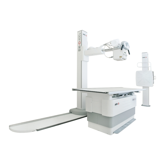
- Page 1 DX-D 400 (type 5420 / 100) User Manual Technical Publication 0232F EN 20191213...
- Page 3 DX-D 400 User Manual REVISION HISTORY REVISION DATE REASON FOR CHANGE JAN 10, 2011 First edition OCT 16, 2013 IEC Standards Update and Grids Update MAR 09, 2015 Removed Detector Models OCT 15, 2018 New logo, new system label, Applied parts...
- Page 4 DX-D 400 User Manual ADVISORY SYMBOLS The following advisory symbols will be used throughout this manual. Their application and meaning are described below. DANGERS ADVISE OF CONDITIONS OR SITUATIONS THAT IF NOT HEEDED OR AVOIDED WILL CAUSE SERIOUS PERSONAL INJURY OR DEATH.
-
Page 5: Table Of Contents
DX-D 400 User Manual TABLE OF CONTENTS Section Page INTRODUCTION ............ -
Page 6: Section Page
........4.1.2 DX-D 400 Analog Control Panel ....... . - Page 7 DX-D 400 User Manual Section Page Receptor Assembly (Table and Wall Stand) ......
- Page 8 DX-D 400 User Manual Section Page DX-D OVERLAY CONSOLE AND DX-D OVERLAY CONSOLE WITH APR ........
- Page 9 DX-D 400 User Manual Section Page TECHNICAL SPECIFICATIONS ......... . .
- Page 10 DX-D 400 User Manual 0232F EN 20191213...
-
Page 11: Introduction
INTRODUCTION This manual contains all the necessary information to understand and operate the DX-D 400 X-ray System. It provides a general description, safety information, operating instructions and specifications concerning the equipment. This manual is not intended to teach radiology or to make any type of clinical diagnosis. -
Page 12: General Features
DX-D 400 User Manual The Generator Cabinet comprises the Power Module (which contains the power and control components) and the High Voltage Transformer. The operator controls and displays for radiographic operations are shown on one of the following Consoles: the DX-D Overlay Console, the DX-D Overlay Console with APR, the DX-D Touch Screen Console or the Software Console of the NX Workstation. - Page 13 DX-D 400 User Manual RAD Table: Fixed height or Elevating Table. RAD Table Receptor Assembly with longitudinal motion. Ion Chamber connection (optional). Fixed or Removable Grids. Accessories: Hand-Grips (pair), Compression Band, Lateral cassette holder (24x30 cm or 35x43 cm.) RAD Wall Stand: ...
- Page 14 DX-D 400 User Manual X-Ray Generator: Constant potential high frequency. Three point control by selecting kVp, mA and ms, two point control by selecting kVp and mAs (no AEC), or one point control by selecting kVp with AEC operations.
-
Page 15: Product Identification
DX-D 400 User Manual PRODUCT IDENTIFICATION The major items in the equipment have some identification labels attached to them which provide the following manufacturer and product information. Product. Model. Volts (V), Line Phases, Frequency (Hz), and Power (kVA, kW). -
Page 16: Indications For Use
This equipment is intended for medical prescription use by qualified personnel only. The DX-D 400 is an equipment designed for general radiography in hospitals, clinics and medical practices to provide X-ray radiographic images of the skeleton, skull, chest, abdomen, extremities and other body parts for diagnostic. -
Page 17: Applied Parts
DX-D 400 User Manual APPLIED PARTS Applied Parts refer to parts of the medical equipment that in Normal Use necessarily comes into physical contact with the patient for the medical equipment to perform its function. This RAD equipment includes the following Applied Parts: Tabletop of the RAD Table. - Page 18 DX-D 400 User Manual This page intentionally left blank. 0232F EN 20191213...
-
Page 19: Safety And Regulatory Information
DX-D 400 User Manual SECTION 2 SAFETY AND REGULATORY INFORMATION This section describes the safety considerations, general precautions for patient, operator and equipment in order to perform a safe operation and service tasks. Regulatory information and symbols used in the equipment are detailed in this section to operate it safely. - Page 20 DX-D 400 User Manual OPERATOR AND SERVICE PERSONNEL AUTHORIZED TO USE, INSTALL, CALIBRATE MAINTAIN THIS EQUIPMENT MUST BE AWARE OF THE DANGER OF EXCESSIVE EXPOSURE TO X-RAY RADIATION. IT IS VITALLY IMPORTANT THAT EVERYONE WORKING WITH X-RAY RADIATION IS PROPERLY TRAINED, INFORMED ON THE HAZARDS OF RADIATION AND TAKE ADEQUATE STEPS TO ENSURE PROTECTION AGAINST INJURY.
- Page 21 DX-D 400 User Manual SPECIAL ATTENTION MUST BE GIVEN TO DIAGNOSTIC X-RAY EQUIPMENT SPECIFIED USED COMBINATION WITH ACCESSORIES OR OTHER ITEMS. BE AWARE OF POSSIBLE ADVERSE EFFECT ARISING FROM THESE MATERIALS LOCATED IN THE X- -RAY BEAM. (SEE THE TABLE BELOW FOR THE MAXIMUM EQUIVALENT ATTENUATION OF MATERIALS POSSIBLY LOCATED IN THE X-RAY BEAM).
-
Page 22: Responsibilities
DX-D 400 User Manual RESPONSIBILITIES THIS X-RAY UNIT MAY BE DANGEROUS TO PATIENT AND OPERATOR UNLESS SAFE EXPOSURE FACTORS, OPERATING INSTRUCTIONS MAINTENANCE SCHEDULES ARE OBSERVED. THE EQUIPMENT HEREIN DESCRIBED IS SOLD WITH THE UNDERSTANDING THAT MANUFACTURER, AGENTS, AND REPRESENTATIVES ARE NOT LIABLE FOR... -
Page 23: Maximum Permissible Dose (Mpd)
DX-D 400 User Manual IT IS THE RESPONSIBILITY OF THE PURCHASER / CUSTOMER TO PROVIDE THE MEANS FOR AUDIO AND VISUAL COMMUNICATION BETWEEN THE OPERATOR AND THE PATIENT. IT IS THE RESPONSIBILITY OF THE OPERATOR TO ENSURE THAT ALL THE EXPOSURE PARAMETERS ARE CORRECT... -
Page 24: Radiation Protection
DX-D 400 User Manual RADIATION PROTECTION Although this equipment is built to the highest safety standards and incorporates a high degree of protection against X-radiation other than the useful beam, no practical design of equipment can provide complete protection, nor can any practical design compel the operator to take adequate precautions to prevent the possibility of any persons carelessly, unwisely, or unknowingly exposing themselves or others to X-radiation. - Page 25 DX-D 400 User Manual Observe the following rules for radiation protection of the personnel in the examination room during X-ray exposures: - Wear radiation protective clothing. - Wear a personal dosimeter. - Use the recommended protective materials and devices against radiation.
-
Page 26: Monitoring Of Personnel
DX-D 400 User Manual MONITORING OF PERSONNEL Monitoring of personnel to determine the amount of radiation to which they have been exposed provides a valuable cross check to determine whether or not safety measures are adequate. It may reveal inadequate or improper radiation protection practices and potentially serious radiation exposure situations. -
Page 27: Safety Symbols
DX-D 400 User Manual SAFETY SYMBOLS The following safety symbols may appear in the equipment. Their meaning are described below. Caution. Consult accompanying documents. Safety Symbol. Follow instructions for use, especially those instructions identified with Advisory Symbols to avoid any risk for the Patient or Operator. - Page 28 DX-D 400 User Manual General Mandatory action. Type B applied part. Protection against harmful ingress of water or particulate matter. IP Classification: Ordinary. Ionizing radiation. Non-ionizing electromagnetic radiation. Radiation of Laser apparatus. Do not stare into beam. (Only applicable to equipment with Laser Pointer) Dangerous voltage.
- Page 29 DX-D 400 User Manual Warning: Non-ionizing radiation. Warning: Laser beam. Warning: Electricity. Warning: Do not place fingers between mobile and fixed parts of the equipment, it may cause serious injuries to patient or operator. As well, make sure the patient extremities are correctly positioned into limit areas during operation, movement of parts may cause serious damages to patient.
- Page 30 DX-D 400 User Manual Emergency stop. “Stand-by” power. (Only applies to IEC 60601-1:2005 and IEC 60601-1:2005+AMD1:2012) “ON” power. “OFF” power. “ON” / “OFF” (push-push). Each position, “ON” or “OFF”, is a stable position. Alternating current. Three-phase alternating current. Three-phase alternating current with neutral conductor.
- Page 31 DX-D 400 User Manual Direct current. Both direct and alternating current. Protective Earth (Ground). Earth (Ground). This symbol according to the European Directive indicates that the Waste of Electrical and Electronic Equipment (WEEE) must not be disposed of as unsorted municipal waste and must be collected separately.
-
Page 32: Regulatory Information
DX-D 400 User Manual REGULATORY INFORMATION 2.7.1 CERTIFICATIONS The DX- D400 covered by this Operation Manual is authorized to be marked with CE MARKING in accordance with the provisions of the Council Directive 93 / 42 / EEC as amended by 2007/47/EC concerning Medical Devices. -
Page 33: Protection Against Electric Shock Hazards
DX-D 400 User Manual 2.7.4 PROTECTION AGAINST ELECTRIC SHOCK HAZARDS Protection against electric shock hazards in accordance with Standards: IEC 60601-1:1988, IEC 60601-1:2005 and IEC 60601-1:2005+AMD1:2012, IEC 60601-2-7:1998, IEC 60601-2-54:2009 and IEC 60601-2-54:2009+AMD1:2015. This equipment has been classified as a type-B ( ) device, in accordance with Standard IEC 60601--1 requirements: Class I - - Type B applied parts. -
Page 34: Protection Against Hazards From Unwanted Or Excessive Radiation . 23 2.7.8 Designated Significant Zones Of Occupancy
DX-D 400 User Manual 2.7.8 DESIGNATED SIGNIFICANT ZONES OF OCCUPANCY X-ray equipment specified for examinations that do not need the operator or staff to be close to the patient during normal use shall be provided with means to allow the following control functions from a “Protected Area” (refer to illustration below): Selection and control of modes of operation. - Page 35 DX-D 400 User Manual X-Ray equipment specified for any radiological examination that requires the operator or staff to be close to the patient during normal use (a.e. some pediatric examinations or other types of examinations for patients that may require assistance), shall have at least one “Significant Zone of Occupancy”...
- Page 36 DX-D 400 User Manual Illustration 2-2 Radiographic Examination on any Patient Support or any Table X-RAY TUBE Focal Spot Phantom X--Ray Receptor Patient Support RAD TABLE S = SIGNIFICANT ZONE OF OCCUPANCY MINIMUM AREA 60 x 60 cm MINIMUM HEIGHT ABOVE THE FLOOR 200 cm...
-
Page 37: Distribution Of Stray Radiation
DX-D 400 User Manual 2.7.9 DISTRIBUTION OF STRAY RADIATION Measurement conditions to determine the distribution of Stray Radiation in the Significant Zone of Occupancy are in accordance with IEC 60601--1--3:1994, 2008 and 2013. Exposure Parameters: RAD mode, 150 kVp, 20 mAs. - Page 38 DX-D 400 User Manual Illustration 2-3 Distribution of Stray Radiation with the Receptor in Vertical Position. STRAY RADIATION (μGy/h) Protective Device Wall Patient Support X--Ray Receptor CHEST UNIT SIGNIFICANT ZONE OF OCCUPANCY Phantom SIGNIFICANT ZONE OF OCCUPANCY AT THE RIGHT SIDE OF THE CHEST UNIT...
- Page 39 DX-D 400 User Manual Illustration 2-4 Distribution of Stray Radiation with the Receptor in Horizontal Position. 9 10 11 12 13 14 15 STRAY RADIATION (μGy/h) SIGNIFICANT ZONE OF OCCUPANCY AT THE LEFT SIDE OF THE RAD TABLE (CATHODE) RAD TABLE...
-
Page 40: Electromagnetic Compatibility (Emc)
DX-D 400 User Manual ELECTROMAGNETIC COMPATIBILITY (EMC) This equipment generates, uses, and can radiate radio frequency energy. The equipment may cause radio frequency interference to other medical or non medical devices and to radio communications. To provide reasonable protection against such interference, this equipment complies with emissions limits for a Group 1 -- Class A Medical Devices Directive as stated in IEC 60601--1--2: 2007 and 2014. - Page 41 DX-D 400 User Manual It is customer responsibility to assure that this equipment and vicinity equipment complies the value of radio frequency interferences shown in General Regulation for safety according to IEC 60601-1-2: 2007 and 2014 Tables as described in this section.
- Page 42 DX-D 400 User Manual GUIDANCE AND MANUFACTURER’S DECLARATION - - ELECTROMAGNETIC IMMUNITY (IEC 60601-1-2:2007) The DX- -D400 radiographic room is intended for use in the electromagnetic environment specified below. The customer or the user of The DX- -D400 radiographic room should assure that it is used in such an environment.
- Page 43 DX-D 400 User Manual GUIDANCE AND MANUFACTURER’S DECLARATION - - ELECTROMAGNETIC IMMUNITY (IEC 60601-1-2:2007) The DX- -D400 radiographic room is intended for use in the electromagnetic environment specified below. The customer or the user of The DX- -D400 radiographic room should assure that it is used in such an environment.
- Page 44 DX-D 400 User Manual RECOMMENDED SEPARATION DISTANCES BETWEEN PORTABLE AND MOBILE RF COMMUNICATIONS EQUIPMENT AND THE RADIOGRAPHIC ROOM (IEC 61601-1-2:2007) The DX- -D400 radiographic room is intended for use in an electromagnetic environment in which radiated RF disturbances are controlled. The customer or the user of The DX- -D400 radiographic room can help prevent electromagnetic interference by maintaining a minimum distance between portable and mobile RF communications equipment (transmitters) and The DX- -D400 radiographic room as recommended below, according to the maximum output power of the communications equipment.
- Page 45 DX-D 400 User Manual GUIDANCE AND MANUFACTURER’S DECLARATION - ELECTROMAGNETIC IMMUNITY (IEC 61601-1-2:2014) The DX- -D400 radiographic room is intended for use in the electromagnetic environment specified below. The customer or Operator of The DX- -D400 radiographic room should assure that it is used in such an environment.
- Page 46 DX-D 400 User Manual GUIDANCE AND MANUFACTURER’S DECLARATION - ELECTROMAGNETIC IMMUNITY (IEC 60601-1-2:2014) The DX- -D400 radiographic room is intended for use in an electromagnetic environment specified below. The customer or Operator of thisRadiographic Room should assure that it is used in such an environment.
- Page 47 DX-D 400 User Manual IMMUNITY REQUIREMENTS TO RF WIRELESS COMMUNICATIONS EQUIPMENT (IEC 60601-1-2:2014) The DX- -D400 radiographic room is intended for use in an electromagnetic environment specified below. The customer or Operator of The DX- -D400 radiographic room should assure that it is used in such an environment.
- Page 48 DX-D 400 User Manual QUANTITATIVE INFORMATION The following tables show the Quantitative Information associated Note to this equipment according to the StandardIEC 60601- -1- -3:2008 and IEC 60601- -1- -3:2008+AMD1:2013. These tables illustrate loading factors for image performance and supply Dose indication examples.
- Page 49 DX-D 400 User Manual Quantitative Information Loading Factors Parameter Selection Filtrat. Measured Doses 0.012 Small 0.016 0.025 7.479 10.795 0.036 Small 0.087 0.136 4.906 7.682 0.213 13 13 13x13 Large 0.836 1.307 9.407 14.125 1.962 Large 3.073 4.802 17.286 23.863 6.629...
- Page 50 DX-D 400 User Manual Quantitative Information Loading Factors Parameter Selection Filtrat. Measured Doses 0.012 Small 0.046 0.072 21.746 113.713 0.379 Small 0.252 0.394 14.195 79.388 2.205 13 13 13x13 Large 39.4 2.587 4.042 29.103 157.649 21.896 Large 191.4 10.009 15.639 56.299...
- Page 51 DX-D 400 User Manual Quantitative Information Loading Factors Parameter Selection Filtrat. Measured Doses 0.012 Small 0.087 0.136 40.753 378.000 1.260 Small 0.461 0.702 25.909 256.070 7.113 13 13 13x13 Large 74.5 4.674 7.303 52.582 511.763 71.078 Large 366.7 18.374 28.709 103.353...
- Page 52 DX-D 400 User Manual Quantitative Information Loading Factors Parameter Selection Filtrat. Measured Doses 0.012 Small 0.131 0.205 61.550 854.348 2.848 Large 11.2 0.698 1.091 39.282 562.852 15.635 13 13 13x13 Large 7.136 11.149 80.276 1132.591 157.304 Large 448.9 28.400 44.375 127.800...
- Page 53 DX-D 400 User Manual Quantitative Information Loading Factors Parameter Selection Filtrat. Measured Doses 0.012 Small 0.194 0.303 90.897 1611.652 5.372 Large 19.1 1.037 1.620 58.304 7.682 0.213 13 13 13x13 Large 164.1 10.722 16.753 120.620 2195.061 304.870 Large 823.7 43.078 67.310...
- Page 54 DX-D 400 User Manual Quantitative Information Loading Factors Parameter Selection Filtrat. Measured Doses 0.012 Small 0.253 0.395 118.573 2493.391 8.311 Large 24.4 1.375 2.148 77.331 1679.791 46.661 13 13 13x13 Large 239.3 14.530 22.704 163.467 3508.591 487.304 Large 882.9 59.548 93.043...
- Page 55 Agfa. If the device malfunctions and may have caused or contributed to a serious injury of a patient, Agfa must be notified immediately by telephone, fax or written correspondence to the following address: Agfa Service Support - local support addresses and phone numbers are listed on www.agfa.com...
- Page 56 DX-D 400 User Manual This page intentionally left blank. 0232F EN 20191213...
- Page 57 DX-D 400 User Manual SECTION 3 START UP AND SHUTDOWN START UP WITH X-RAY GENERATOR CONTROL The System should be powered by the same Room Electrical Cabinet where the X-ray Generator is connected, that is, the whole System will be powered from the same Electrical Cabinet.
- Page 58 DX-D 400 User Manual Press the X-Ray Generator Control ON button, the Green Lamp turns Turn ON the NX Workstation. Illustration 3-1 Start Up sequence Room Electrical Cabinet NX Workstation X-Ray Generator Control 0232F EN 20191213...
- Page 59 DX-D 400 User Manual SHUTDOWN ROUTINE WITH X-RAY GENERATOR CONTROL To turn the System OFF: Turn OFF the NX Workstation. Press the X-Ray Generator Control OFF button, the Green Lamp turns OFF. Turn OFF the Room Electrical Cabinet Switch (with the Emergency Switch in OFF position).
- Page 60 DX-D 400 User Manual This page intentionally left blank. 0232F EN 20191213...
- Page 61 DX-D 400 User Manual SECTION 4 OPERATION USE THE EQUIPMENT HAND-GRIPS TO CONTROL AND DRIVE THE UNIT MOVEMENTS, NEVER PUSH DIRECTLY ON THE RECEPTOR, X-RAY TUBE OR COLLIMATOR. MONITOR THE SYSTEM MOVEMENTS WITH SPECIAL CARE. AVOID ANY IMPACT OF THE SYSTEM ON FLOOR, CEILING OR OTHER ELEMENTS IN THE ROOM.
- Page 62 DX-D 400 User Manual 4.1.2 DX-D 400 ANALOG CONTROL PANEL Illustration 4-1 DX-D 400 Analog Control Panel Rotational Movement Horizontal Movement Transverse Movement Vertical Movement Light Indicators All Movements HORIZONTAL MOVEMENT: Activate this button to allow horizontal movement of Column in order to achieve SID (Source-Image Distance) with respect to RAD Wall Stand Receptor.
- Page 63 DX-D 400 User Manual VERTICAL MOVEMENT: Press and hold this button to allow vertical movement of the Tube-Collimator Assembly in order to achieve the desired SID with respect to the Horizontal Receptor. This control is also used to vertically position the Tube-Collimator Assembly with respect to the Vertical Receptor.
- Page 64 4.1.2.1 VERTICAL SID REFERENCE LABEL DX-D 400 with Analog Control Panel and Fixed height Table includes a Vertical SID reference label to provide the operator a quick SID reference. The Horizontal Receptor SID reference is indicated as a label stuck in the Column, which reference point is the lower part of the Column carriage.
- Page 65 DX-D 400 User Manual 4.1.3 DX-D 400 DIGITAL CONTROL PANEL Illustration 4-3 DX-D 400 Digital Control Panel SID Display Angle Display Centering Indicator Transversal Movement Horizontal Movement Rotational Vertical Movement All Movements All Movements After the System is turned ON, a start up routine begins and the Control Panel shows for three seconds the software version (a.e.
- Page 66 DX-D 400 User Manual HORIZONTAL MOVEMENT: Activate this button to allow horizontal movement of Column in order to achieve SID (Source-Image Distance) with respect to RAD Wall Stand Receptor. Also this control is used to horizontally position Column with respect to RAD Table Receptor. Release button to lock in position.
- Page 67 DX-D 400 User Manual TRANSVERSE MOVEMENT: Activate this button to allow transverse movement of Tube-Collimator Assembly. Release button to lock in position. LOCK This movement is provided with a detent when the Tube-Collimator Assembly is centered with respect to the RAD Table Receptor (“LOCK” indicator lits).
- Page 68 DX-D 400 User Manual 4.1.4 RALCO MANUAL COLLIMATOR R225/R225 DHHS Collimator controls consist of a button to switch on the Collimator lamp and two knobs to open or close the internal blades of the Collimator. When pressing the Collimator Lamp push-button, the Collimator light and an optional Laser light turn on.
- Page 69 DX-D 400 User Manual 4.1.5 RALCO AUTOMATIC COLLIMATOR R225ACS Collimator controls: Collimator Display Manual Blade Control Automatic Mode Indicator (Green) System not ready Indicator (Red) Manual Mode Indicator (Yellow) Change of Filter Collimator Lamp Control (Led “ON”) Retractable Metric Tape...
- Page 70 DX-D 400 User Manual DOSEMETER DEVICE (OPTIONAL) The optional Dosemeter device is related to the Collimator installed in the Tube Stand. It is used for simultaneously determining the dose area product, dose area product rate and irradiation time. The usual compatible Dosemeter devices are VacuDAP 2004 Series.
- Page 71 DX-D 400 User Manual THE MAXIMUM PATIENT WEIGHT SUPPORTED WITH THE TABLE-TOP AT ANY POSITION IS 350 KG (771 LBS) EVENLY DISTRIBUTED OVER THE SURFACE OF THE TABLE-TOP. EXCEEDING THIS LIMIT MAY CAUSE EQUIPMENT DAMAGE OR INJURY TO THE PATIENT.
- Page 72 DX-D 400 User Manual TABLE-TOP BRAKE PEDAL: The Table-Top is provided with four-way floating movement for better patient positioning. Press and hold Pedal in order to release longitudinal and transverse brakes of Table-Top. Release Pedal to apply brakes. The transverse motion is blocked when the Table-Top is centered with respect to its horizontal axis.
- Page 73 DX-D 400 User Manual ON / OFF / EMERGENCY OFF SWITCH: The Table and the Floor Mounted Tube Stand are ON whenever the Generator Console is ON and the Table Emergency OFF Switch is not depressed. The Table and the Floor Mounted Tube Stand are OFF when the Generator Console is OFF or when the Emergency OFF Switch is pressed.
- Page 74 DX-D 400 User Manual Illustration 4-5 Elevating Table Pedals Table-Top Down Table-Top TABLE-TOP MOVEMENT PEDALS: Step on any of the two pedals (at both ends of the Pedal row) in order to release longitudinal and transverse brakes, this allows free movement of Table-Top for better positioning of patient.
- Page 75 DX-D 400 User Manual 4.3.3 HAND GRIPS (OPTIONAL) The Hand Grips are used by patients and operators to keep their hands away from the Tabletop edges and make the patient feel safe while the table-top is being positioned. Insert the Hand Grip in the rails and fix it at the desired position by turning clockwise the Grip.
- Page 76 DX-D 400 User Manual 4.3.4 COMPRESSION BAND (OPTIONAL) This device supplies compression to the anatomical area of interest in order to avoid unnecessary movements. It is mounted on the Tabletop rails. Install both brackets of the Compression Band in the Table-top rails, roll the band in the shaft, engage the end of the band in with the hooks and use the lever lock or unlock the Compression Band to get the required tension of the Band.
- Page 77 DX-D 400 User Manual 4.3.5 LATERAL DETECTOR HOLDER (OPTIONAL) The Lateral Detector Holder is used for Table lateral work, including knee, shoulder, skull, etc. This Lateral Detector Holder is installed directly on the Tabletop rails. Insert the Hand Grip in the rail and fix it at the desired position by turning clockwise the Grip.
- Page 78 DX-D 400 User Manual 4.3.6 LATERAL DETECTOR HOLDER ON TABLE (OPTIONAL) The Lateral Detector Holder is used for Table lateral work, including knee, shoulder, skull, etc. This Lateral Detector Holder is placed directly on the Tabletop. It can hold a Detector of 35 x 43 cm.
- Page 79 DX-D 400 User Manual 4.3.7 LATERAL DETECTOR HOLDER WITH TROLLEY This mobile detector holder is designed to accommodate portable DR detectors of 35x43 cm (14”x17”) . Illustration 4-9 Lateral Detector Holder 35x43 with Trolley Insert the portable DR Detector in the Support, the orientation is always landscape.
- Page 80 DX-D 400 User Manual The Holder is adjustable for height, the vertical travel of the Detector is 750 mm (29.5”). To move up/down the Detector Support: Loosen CCW the Vertical Lock Lever To get free the Detector Support. Hold the Detector Support during this procedure to avoid unexpected falls down.
- Page 81 DX-D 400 User Manual To move the Holder in order to place it in its working position or to store it, proceed as indicated below: Unlock all wheels. Push the Holder from its Vertical Bar and carry it where corresponds.
- Page 82 DX-D 400 User Manual RAD WALL STAND The RAD Wall Stand enables radiographic operations at different positions within the range of the Receptor Assembly vertical movement. ON / OFF: The equipment is turned ON / OFF when the X-ray Generator is turned ON / OFF.
- Page 83 DX-D 400 User Manual RAD WALL STAND - MANUAL TILTING The RAD Wall Stand -- Manual Tilting enables radiographic operations at different positions within the range of the Vertical Carriage travel, adjustable tilting angles as well as rotation of the Receptor Assembly.
- Page 84 DX-D 400 User Manual ON / OFF: The equipment is turned ON / OFF when the X-ray Generator is turned ON / OFF. RECEPTOR ASSEMBLY: The Wall Receptor can house a Cassette Film, CR or a Digital Detector with the following characteristics: Chin Rest.
- Page 85 DX-D 400 User Manual 4.5.1 TILTING OF RECEPTOR ASSEMBLY The Receptor Assembly allows a tilting range from --20 to a horizontal position of 90 is the vertical position). A mechanical detent is provided to lock the Receptor Assembly at 0 (vertical position).
- Page 86 DX-D 400 User Manual 4.5.2 ROTATION OF RECEPTOR ASSEMBLY The Receptor Assembly allows a rotation range of 90 clockwise if the Removable Grid is left loading, or a rotation range of 90 counterclockwise if the Removable Grid is right loading. The vertical position is 0 Push the Lever Lock located at the right side of the Receptor Assembly and manually rotate the Receptor Assembly to the desired position.
- Page 87 DX-D 400 User Manual Horizontal Rotation of the Receptor Assembly is not allowed. The Receptor Assembly may be damaged if it bumps the Column. From the Horizontal position of the Receptor, tilt the Assembly a minimum of 45 . Rotate the Assembly and...
- Page 88 DX-D 400 User Manual 4.5.3 ARM SUPPORT (OPTIONAL) The Wall Stand can be prepared to hold an Arm Support. In that case, the side of the Column Carriage includes an Arm Support holder with a knob. Insert the Arm Support in the holder and screw the knob.
- Page 89 DX-D 400 User Manual RECEPTOR ASSEMBLY (TABLE AND WALL STAND) The Receptor Assembly may include a Fixed Receptor (DR) or a Portable Receptor (Cassette/CR/DR). The Receptor Assembly for Portable Receptors include a Tray to conveniently load the Receptor. The Receptor Assembly may also house other optional parts such as the Grid (Fixed or Removable) and the Ion Chamber, used for AEC exposures.
- Page 90 DX-D 400 User Manual HORIZONTAL MOVEMENT OF THE TABLE RECEPTOR ASSEMBLY The Receptor can be moved beneath the Tabletop to the desired position. Press and hold the brake button to unlock the Receptor and move it manually. Illustration 4-15 Receptor Brake Buttons...
- Page 91 DX-D 400 User Manual 4.6.2 RECEPTORS The Table and Wall Stand are compatible with a wide range of Receptors: Type of Receptors Cassette-Film or Computerized Radiography (CR) with Bucky Assembly Fixed Digital Detector Portable Digital Detector (wired) Portable Wireless Digital Detector wifi connected...
- Page 92 DX-D 400 User Manual 4.6.3 TRAY FOR CASSETTE FILM OR CR (TABLE OR WALL STAND) The Bucky Assembly is installed on a carriage, below the Tabletop. It contains a manual Cassette Tray, which accepts all the standard Cassette / CR sizes from 13x18 cm to 35x43 cm (5x7”...
- Page 93 DX-D 400 User Manual 4.6.4 FIXED RECEPTOR ASSEMBLY (TABLE OR WALL STAND) It includes the Detector, Detector Cabinet with fixed or removable Grid and Ion Chamber Housing. Rad Tables include the Brake Button to move horizontally the Assembly. Brake Button...
- Page 94 DX-D 400 User Manual 4.6.5 PORTABLE RECEPTOR ASSEMBLY (TABLE OR WALL STAND) 4.6.5.1 PORTABLE RECEPTOR ASSEMBLY WITH ROTATING TRAY Illustration 4-16 Portable Receptor Assembly in the Rad Table Tabletop Grid Digital Detector Tray Handle Bar Assembly Lock Button Illustration 4-17...
- Page 95 DX-D 400 User Manual The Portable Receptor Assembly with Rotating Tray has been designed to conveniently house a Receptor, an Ion Chamber and a Grid. It can also provide the system with information about the position and status of the Grid and Detector.
- Page 96 DX-D 400 User Manual LOADING AND UNLOADING THE TRAY Grab the Handle and pull the Tray until it is completely out. Then place the Detector, centered on the Tray and insert it in the tray. Push slightly the end-stops with the Detector end until it is fitted in the frame of the tray.
- Page 97 DX-D 400 User Manual ROTATING THE TRAY Pull out the Receptor Tray to the end of its travel (Rotating Position). Insert the Rceptor in the Tray. Push the Tray Counterclockwise until it rotates 90 to achieve Portrait position. Guide the Receptor Cable through the Cable Clips and insert the Tray.
- Page 98 DX-D 400 User Manual Illustration 4-20 Portable Receptor Assembly with Non-Rotating Tray in Rad Table and Wall Stand RAD Table Wall Stand Brake Bar Brake Button in a Portable Receptor Assembly (only for Rad Table) LOADING AND UNLOADING THE TRAY Grab the Handle and pull the Tray until it is completely out.
- Page 99 DX-D 400 User Manual Push the Detector towards the end Stop and carefully remove the Detector . CABLE GUIDING IN TETHERED DETECTORS In Systems with a Single panel for Wall Stand and Table or Systems with external connection of the Detector, it is recommended to use a Extensible...
- Page 100 DX-D 400 User Manual 4.6.6 GRIDS Grids are intended to reduce scattered radiation and significantly enhance image quality. Before using the Grid, clean the front and back side with a dry cloth to remove dust and dirt. The Wall Stand and the Table may hold a Removable Grid. The Grids are labelled 100 cm (40”), 150 cm (59”) or 180 cm (70”).
- Page 101 DX-D 400 User Manual 4.6.7 USING AND MAINTAINING THE DIGITAL DETECTOR Before Exposure, check the equipment daily and confirm that it works properly. The action of the Air-Conditioning or Heating may produce condensation in the equipment, wait until the condensation evaporates before performing an exposure.
- Page 102 DX-D 400 User Manual X-RAY BEAM ALIGNMENT WITH RESPECT TO PATIENT After selecting RAD parameters for the technique to be performed: Point the X-Ray Tube-Collimator Assembly to the Image Receptor. Center the Collimator light, which corresponds to the X-Ray beam, with respect to receptor.
- Page 103 DX-D 400 User Manual ALWAYS SELECT THE CORRECT FIELD SIZE TO AVOID EXCESSIVE RADIATION. THE X-RAY BEAM AXIS AND THE REFERENCE AXIS OF THE PLANE OF INTEREST COINCIDE AND ARE ORTHOGONAL WITH RESPECT TO THE PLANE OF INTEREST, IN EXAMS...
- Page 104 DX-D 400 User Manual This page intentionally left blank. 0232F EN 20191213...
- Page 105 DX-D 400 User Manual SECTION 5 DX-D TOUCH SCREEN CONSOLE All controls, indicators and displays located on the DX-D Touch Screen Console are functionally grouped. Also the Console shows different menus (screens) according to the selected operations. Use the operating controls as described in this manual. Any other...
- Page 106 DX-D 400 User Manual RADIOGRAPHY AND GENERAL CONTROLS 5.1.1 POWER ON / OFF ON: The Generator and the Console are turned ON by pressing and holding for two seconds the “ON / OFF Switch” of the Console Housing. This starts the application and the last parameters and workstation used are automatically selected.
- Page 107 DX-D 400 User Manual 5.1.3 WORKSTATION SELECTION The Workstations are configured according to the customer preferences during the installation procedure (Icon, X-ray Tube, Device, Ion Chamber, etc.). Each button selects its respective Workstation (only the selected button is highlighted). The Workstations are directly selected by touching the respective button.
- Page 108 DX-D 400 User Manual 5.1.4 FOCAL SPOT INDICATOR A Focal Spot indicator shows the selected Focal Spot of the X-ray Tube: “Small” or “Large”. The Focal Spot is changed by touching this indicator. It keeps kVp and constant mAs, whenever it is possible. The mA value available is set according to maximum power, instantaneous power, space charge, etc.
- Page 109 DX-D 400 User Manual 5.1.5 RADIOGRAPHIC PARAMETERS For Radiographic Operating Modes refer to Section 7.3. Note RADIOGRAPHIC DISPLAYS: They are divided in the kVp, mA, mAs and Time (s) Displays where the following data are shown. kVp DISPLAY shows the radiographic kVp value selected for the technique.
- Page 110 DX-D 400 User Manual INCREASE / DECREASE: Radiographic technique values are increased or decreased by selecting the respective RAD Display (which will be highlighted) and changing the value with the “Increase” or “Decrease” buttons. The values increase or decrease step-by-step each time the corresponding button is touched, and change faster when either of them is touched continuously.
- Page 111 DX-D 400 User Manual If after touching any of these buttons the technique value is Note blocked, it could mean that: Radiographic Parameters Blockage. When any of the maximum or minimum radiographic parameter limits are reached, its related Display flashes accompanied by an information message.
- Page 112 DX-D 400 User Manual The following table indicates the different Information Messages and Display flashing that may appear in the Console when increasing or decreasing one of the exposure parameters. DISPLAY FLASHING INFORMATION MESSAGE INFORMATION MESSAGE DESCRIPTION DESCRIPTION Min kVp...
- Page 113 DX-D 400 User Manual AUTOMATIC EXPOSURE CONTROL (AEC) Automatic Exposure Control (AEC) produces consistent image density with excellent contrast regardless of the radiographic technique selected. The AEC module comprises the controls for the selection of the Exposure Detector Fields (Ion Chamber), the Film/Screen Combination, Image Density Compensation and AEC Reset.
- Page 114 DX-D 400 User Manual FILM / SCREEN COMBINATION: Each of these buttons allows adjustment of the mAs in relation to a programmed Film / Screen combination that may be in use slow, medium, or fast respectively (200, 400, 800). Each time a Film / Screen button is selected (highlighted), the others are automatically deselected.
- Page 115 DX-D 400 User Manual ANATOMICAL PROGRAMMER (APR) The Anatomical Programmer (APR) module is comprised of the controls which select the Patient Size and its corresponding “Body Region / Anatomical View / Projection”. The process is shown on the APR Display.
- Page 116 DX-D 400 User Manual APR DISPLAY: It shows the different Body Regions and Anatomical Views available for each APR technique and the final APR selection. As the area of the APR Display is limited in length, the name of some Regions, Views or Projections is abbreviated.
- Page 117 DX-D 400 User Manual STORE: All parameters of the APR techniques may be manually rewritten as required by the operator. If the operator determines that some factors in an APR technique should be re-programmed, perform the following procedure: Select an APR technique and modify the factors and selections of Workstations or AEC which require to be re-programmed.
- Page 118 DX-D 400 User Manual MODIFY: After touching this button, the Console shows a Password pop--up screen, enter the password required to access to the “Modify” options. The default Operator Password is “1111”, but it can be changed by a new one with the “Change Password”...
- Page 119 DX-D 400 User Manual EDIT: After touching this button, the Console shows the “Edit” menu with the different controls to create, modify or delete the APR techniques, or change the operator password. Exposures are inhibited when the “Edit” menu is shown on the Note Console.
- Page 120 DX-D 400 User Manual This warning message is shown until the parameters / selections Save changes before exiting for the new created APR Technique are set from “Edit” menu QUIT: Touch this button to exit from the “Edit” options and go back to the previous screen (Restore Default / Edit / Exit).
- Page 121 DX-D 400 User Manual PATIENT SIZE: These buttons are used to select the Patient Size (small, medium or large size) for the APR technique chosen. Six patient sizes are available. The three upper buttons select “Small”, “Medium” and “Large” adult sizes (only one selected at the same time).
- Page 122 DX-D 400 User Manual A virtual keyboard appears on the screen. Write the name of the new Region, View or Projection and click on “Enter”. The new label of the Region, View or Projection is located in the last position of the list.
- Page 123 DX-D 400 User Manual SAVE: Touch this button to save all the changes performed in the “Edit” menu before exiting. Illustration 5-2 Creating a New APR Technique 1. Touch on “Modify” button. The system requires the operator password and the confirmation.
- Page 124 DX-D 400 User Manual Illustration 5-3 Modifying an existing APR Technique 1. Touch on a Patient size to select an APR Technique 2. Touch on the selector of the Region, View, Projection to be modified. 3. Modify the parameter and/ or AEC selection and/or workstation.
- Page 125 DX-D 400 User Manual EXPOSURE CONTROLS AND STATUS INDICATORS Radiographic exposures from the Console are made with the “Prep” (preparation) and “Expose” buttons on the Handswitch. The status of the Prep exposure is indicated by the “Ready” and “X-ray On” indicators for the duration of the exposure.
- Page 126 DX-D 400 User Manual SELF-DIAGNOSIS INDICATORS Self-Diagnosis indicators identify a malfunction in the system alerting operator about error existence that inhibits exposure. During normal operation of the system, these indicators are directly shown on the lower area of the console or as an error code close to the “Reset Error”...
- Page 127 DX-D 400 User Manual TECHNIQUE ERROR: If it activates during exposure it means that: TECH The exposure has been interrupted by the “Security Timer” because of a system failure. Call Field Service. This error can also be shown: after an APR technique selection to advise that exposure parameters ...
- Page 128 DX-D 400 User Manual ERROR CODES Error codes indicate the potential cause of a system failure. Error codes are shown on the Console, at the same time an alarm sounds. Correct the error cause and keep touched the “Reset” button until the Console indication disappears.
- Page 129 DX-D 400 User Manual Table 5-1 Error Codes ERROR DESCRIPTION WHAT TO DO System failure. This indication may appear together with an -- -- -- -- -- -- Turn the Generator OFF and ON. error on the Console, and indicates that the error is not on Display If the equipment remains inoperative, turn it OFF and call Field Service.
- Page 130 DX-D 400 User Manual Table 5-1 (cont.) Error Codes ERROR DESCRIPTION WHAT TO DO Turn the Generator OFF and ON. E19, E20 System failure. If the equipment remains inoperative, turn it OFF and call Field Service. E21, E22 Incorrect selection of the X-ray Tube.
- Page 131 DX-D 400 User Manual Table 5-1 (cont.) Error Codes ERROR DESCRIPTION WHAT TO DO E41 to E46 System failure related to Dosimeter. Collimator Error. A failure on the Automatic Collimator has been detected (blades are full open or in movement during Touch the “Reset”...
- Page 132 DX-D 400 User Manual This page intentionally left blank. 0232F EN 20191213...
- Page 133 DX-D 400 User Manual SECTION 6 DX-D OVERLAY CONSOLE AND DX-D OVERLAY CONSOLE WITH APR All controls, indicators and displays located on the Control Console are positioned depending upon their functions. Use the operating controls as described in this manual, any other...
- Page 134 DX-D 400 User Manual RADIOGRAPHY AND GENERAL CONTROLS 6.1.1 POWER ON / OFF ON: The Generator is turned ON by pressing this push-button. This starts a power-up routine which is shown on the Console (a.e. P05.3 = Vers.5, Rev.3). After the power-up routine the last workstation used will be automatically selected.
- Page 135 DX-D 400 User Manual Note in the following table the configuration of the Workstation assigned for each push-button. PUSH-BUTTONS WORKSTATION (Tube, Device, etc.) Note.- - Workstation data such as X-ray Tube, Device, Ion Chambers, etc... must be registered. 6.1.3 FOCAL SPOT INDICATORS AND SELECTORS LARGE FOCAL SPOT: Indicates that the “Large Focal Spot”...
- Page 136 DX-D 400 User Manual 6.1.4 RADIOGRAPHIC PARAMETERS kV DISPLAY can show: The radiographic kV value selected for the technique. The actual X-ray Tube heat unit value after pressing the “On” push-button (Refer to Section 6.6). The error messages during a system fault, preceded by the letter “E”...
- Page 137 DX-D 400 User Manual INCREASE / DECREASE: Radiographic technique values are increased or decreased by pressing the respective push-buttons. The values increase or decrease step-by-step each time the corresponding push-button is pressed, and changes faster when either of them is pressed continuously.
- Page 138 DX-D 400 User Manual AUTOMATIC EXPOSURE CONTROL (AEC) Automatic Exposure Control (AEC) produces consistent film density with excellent contrast regardless of the radiographic technique selected. The AEC module comprises the controls for the selection of the Exposure Detector Fields (Ion Chamber), the Film/Screen Combination, Film Density Compensation and AEC Reset.
- Page 139 DX-D 400 User Manual AEC RESET: If the exposure is aborted by the AEC back-up timer, the indicator on the “AEC Reset” push-button blinks accompanied of an audible alarm. Next exposure is inhibited until the AEC function is reset by pressing the “AEC Reset”...
- Page 140 DX-D 400 User Manual The APR is activated when one of the three Patient Size (small, medium or large size) is selected (push-button lighted), and it is deactivated when all of them are deselected. The language pack of the factory pre-programmed APR...
- Page 141 DX-D 400 User Manual APR TECHNIQUE CHANGES The APR techniques are factory pre-programmed to standard technique sets. All the parameters and selections for the APR techniques may be modified by the operator and stored in the non-volatile memory for later use.
- Page 142 DX-D 400 User Manual EXPOSURE CONTROLS AND INDICATORS Radiographic exposures from the Control Console are made with the “Prep” (preparation) and “Expose” (X-ray exposure) push-buttons or with the Handswitch. The status of the exposure is indicated by the “Ready” and “X-ray On”...
- Page 143 DX-D 400 User Manual X-RAY HANDSWITCH Radiographic exposures can also be initiated with the X-ray Handswitch which is connected to the Control Console. Prep The X-ray Handswitch button has three positions: “Off”, “Preparation”, and “X-ray Exposure”, which operate in the same way that “Prep” and “Exp”...
- Page 144 DX-D 400 User Manual SELF-DIAGNOSIS INDICATORS Self-Diagnosis indicators identify a malfunction in the system alerting operator about error existence that inhibits exposure. During normal operation of the system, these indicators are directly shown on the APR Display or as an error code on the kV Display.
- Page 145 DX-D 400 User Manual TECHNIQUE ERROR: If activates during exposure it means that: TECH The exposure has been interrupted by “Security Timer” because of a failure in the system. Call Field Service. This error can also be shown: after an APR technique selection to advise that exposure parameters ...
- Page 146 DX-D 400 User Manual Table 6-1 Error Codes ERROR DESCRIPTION WHAT TO DO System failure. This indication may appear together with an -- -- -- -- -- -- Turn the Generator OFF and ON. error on the Console, and indicates that the error is not on Display If the equipment remains inoperative, turn it OFF and call Field Service.
- Page 147 DX-D 400 User Manual Table 6-1 (cont.) Error Codes ERROR DESCRIPTION WHAT TO DO Turn the Generator OFF and ON. E19, E20 System failure. If the equipment remains inoperative, turn it OFF and call Field Service. E21, E22 Incorrect selection of the X-ray Tube.
- Page 148 DX-D 400 User Manual Table 6-1 (cont.) Error Codes ERROR DESCRIPTION WHAT TO DO E41 to E46 System failure related to Dosimeter. Collimator Error. A failure on the Automatic Collimator has been detected (blades are full open or in movement during Press the “AEC Reset”...
- Page 149 DX-D 400 User Manual SECTION 7 OPERATING SEQUENCES START-UP ROUTINE Start-up the System as described in Section 3. X-RAY TUBE WARM-UP PROCEDURE Before effecting X-ray exposures ensure that the Tube is properly warmed-up. Make sure that no persons will be inadvertently exposed to unnecessary X-rays during this procedure.
- Page 150 DX-D 400 User Manual RADIOGRAPHIC OPERATION RAD operation can be performed in the following modes: Three point control by selecting kVp, mA and Exposure Time independently. Two point control by selecting kVp and mAs independently. mAs selection sets the maximum mA available for the selected Focal Spot and the respective Exposure Time.
- Page 151 DX-D 400 User Manual AEC OPERATION To proper use of AEC requires accurate patient positioning. For examination using AEC, the operator will need to select the desired AEC parameters as follows: Make sure that the X-ray Tube to be used is properly warmed-up.
- Page 152 DX-D 400 User Manual Select “Center” Ion Chamber and Density “Normal - - 0”. Make a RAD exposure and note the exposure mAs and time. For a proper functioning of the AEC, the exposure must not be aborted by the AEC back-up timer, that is, the “AEC Reset”...
- Page 153 DX-D 400 User Manual APR OPERATION An examination using an APR technique could consist of the following: Make sure that the X-ray Tube to be used is properly warmed-up. Position the patient for the examination. Select the “Patient Size” corresponding to the patients anatomy. This operation starts the APR mode.
- Page 154 DX-D 400 User Manual This page intentionally left blank. 0232F EN 20191213...
- Page 155 DX-D 400 User Manual SECTION 8 PERIODIC MANTEINANCE In order to ensure continued safe performance of the equipment, a periodic maintenance program must be established. It is the owner’s responsibility to supply or arrange for this service. There are two levels of maintenance, the first consists of tasks which are performed by the user/operator, and the second are those tasks to be performed by qualified X-ray service personnel.
- Page 156 DX-D 400 User Manual Clean the equipment frequently, particularly if corroding chemicals are present. Clean external covers and surfaces, specially parts in contact with patients, with a cloth moistened in warm water with mild soap. Wipe with a cloth moistened in clean water. Do not use cleaners or solvents of any kind.
- Page 157 DX-D 400 User Manual SECTION 9 TECHNICAL SPECIFICATIONS ENVIRONMENTAL REQUIREMENTS ATMOSPHERIC PRESSURE (hPa) RELATIVE HUMIDITY (%) AMBIENT TEMPERATURE WORKING 10 o C (50 o F) 35 o C (95 o F) 700 hPa 1060 hPa TRANSPORT & STORAGE -20 o C (--4 o F)
- Page 158 DX-D 400 User Manual 9.2.2 INFORMATION RELATED TO RADIATION Radiation Output Accuracy: C.V. (Coefficient of Variation) 0.05 ≤ (Reproducibility related to loading factors) Maximum Symmetrical Radiation Field: Measured at 75 kVp: 160 mm in “X” axis and 240 mm in “Y” axis.
- Page 159 DX-D 400 User Manual RAD TABLE - - FIXED HEIGHT (Refer to Illustration 9-1 and Illustration 9-2) Dimensions Height ......
- Page 160 DX-D 400 User Manual RAD TABLE - - ELEVATING TABLE (Refer to Illustration 9-1 and Illustration 9-2) Dimensions Maximum Height ....900 mm Minimum Height .
- Page 161 DX-D 400 User Manual RAD WALL STAND (Refer to Illustration 9-3) Dimensions Height ......
- Page 162 DX-D 400 User Manual RAD WALL STAND - - MANUAL TILTING (Refer to Illustration 9-4) Dimensions Height ......
- Page 163 DX-D 400 User Manual GRIDS Configurations with non--removable moving grid: Grids for Table ..1 m -- 215 lines/inch -- 12:1 (Carbon Fibre) Grids for Wall Stand . . . 1 m -- 215 lines/inch -- 12:1 (Carbon Fibre) 1.3 m -- 215 lines/inch -- 8:1 (Carbon Fibre)
- Page 164 DX-D 400 User Manual Illustration 9-1 Dimensions of the Equipments in the X-ray System (RAD Table - - Elevating Table). 0232F EN 20191213...
- Page 165 DX-D 400 User Manual Illustration 9-2 Dimensions of the Equipments in the X-ray System (RAD Table - - Fixed Height Table). 0232F EN 20191213...
- Page 166 DX-D 400 User Manual Illustration 9-3 Dimensions of the RAD Wall Stand 381 (15”) 200 (7.8”) 657 (25.8”) 559 (22”) 0232F EN 20191213...
- Page 167 DX-D 400 User Manual Illustration 9-4 IDimensions of the RAD Wall Stand - Manual Tilting 399 (15.7”) 512 (20.1”) 582 (22.9”) 693 (27.2”) 980 (35”) 180 (7.1”) 90º 20º 657 (25.8”) Receptor Assembly 559 (22”) Table-top 0232F EN 20191213...
- Page 168 DX-D 400 User Manual X-RAY GENERATOR 9.3.1 FACTORS GENERATOR SHF-335-1T-LS SHF-335-1T-HS SHF-535-1T-LS SHF-535-1T-HS SHF-635-1T-HS SHF-835-1T-HS MODEL RAPIDT RAPIDT RAPIDT RAPIDT RAPIDT RAPIDT Maximum Power kW 32 kW 50 kW 64 kW 80 kW Maximum mA 400 mA 640 mA 640 mA...
- Page 169 DX-D 400 User Manual 9.3.4 PHYSICAL CHARACTERISTICS DIMENSIONS COMPONENT COMPONENT WEIGHT WEIGHT LENGTH WIDTH HEIGHT X-ray Generator (1 Tube, HSS) 592 mm 360 mm 690 mm 95 Kg X-ray Generator (1 Tube, LSS) 445 mm 360 mm 568 mm 72 Kg...
- Page 170 DX-D 400 User Manual X-RAY TUBES Low Speed -- Rotating Anode, Focal Spots: 0.6 mm / 1.2 mm Anode kHU / kVp: 300 kHU / 150 kVp, Target Angle: 12° E7884X Maximum Specified Energy Input in 1 hour: 150 kVp @ 3408 mAs Inherent Filtration of X-ray Source (Tube + Collimator): refer to Identification Label High Speed -- Rotating Anode, Focal Spots: 0.6 mm / 1.2 mm...
- Page 171 DX-D 400 User Manual APPENDIX A GUIDELINES FOR PEDIATRIC APPLICATIONS PRACTITIONER WILL ULTIMATE RESPONSIBLE OF APPLYING THE PROPER DOSE TO THE PATIENT RADIOGRAPHIC PROCEDURES. PURPOSE OF THESE GUIDELINES IS TO HELP THE PRACTITIONER TO MINIMIZE POTENTIAL RISKS. Use special care when imaging patients outside the typical adult size range.
- Page 172 DX-D 400 User Manual Positioning the pediatric patient: Pediatric patients are not as likely as adults to understand the need to remain still during the procedure. Therefore it makes sense to provide aids to maintaining stable positioning. It is strongly recommended the use of immobilizing devices such as bean bags and restraint systems (foam wedges, adhesive tapes, etc.) to avoid the need of repeating exposures due to...
- Page 173 DX-D 400 User Manual APPENDIX B ANATOMICAL PROGRAMMER MATRIX For DX-D Touch Screen Console, the language of the factory Note pre-programmed APR techniques is configured according to the customer order and it can not be changed by the operator (refer to Section B.1).
- Page 174 DX-D 400 User Manual AVAILABLE LANGUAGE MATRIX APR MATRIX (ENGLISH VERSION) BODY REGION / ORGAN / PROJECTION AP/PA LATERAL SKULL SEMIAXIAL THORAX ODONTOID LATERAL AXIAL SPECIAL AP/PA ORBITA UPPER RIBS C-SPINE LATERAL OBLIQUE OBLIQUE PETROUS AP/PA BONES LOWER RIBS T-SPINE...
- Page 175 DX-D 400 User Manual APR MATRIX (FRENCH VERSION) REGION DU CORPS / ORGANE / PROJECTION AP/PA LATERAL SEMIAXIAL CRANE THORAX ATLAS LATERAL AXIAL SPECIAL AP/PA ORBITAE COTES SUP. COL. CERV LATERAL OBLIQUE OBLIQUE AP/PA M. PEDRO COTES INF. COL. DORS...
- Page 176 DX-D 400 User Manual APR MATRIX (SPANISH VERSION) ZONA CUERPO / ORGANO / PROYECCION AP/PA LATERAL SEMIAXIAL CRANEO TORAX ODONTAL LATERAL AXIAL ESPECIAL AP/PA COSTILLAS COLUMNA ORBITA LATERAL SUPERIORES CERVICAL OBLICUO OBLICUO AP/PA COSTILLAS COLUMNA PEÑASCO LATERAL INFERIORES DORSAL OBLICUO...
- Page 177 DX-D 400 User Manual APR MATRIX (GERMAN VERSION) REGION / ORGAN / PROJEKTION AP/PA LATERAL HALBAX. SCHÄEDEL THORAX DENS LATERAL AXIAL SPEZIAL AP/PA OBERER ORBITA LATERAL RIPPEN OBLIQUE OBLIQUE AP/PA UNTERER STENVERS LATERAL RIPPEN OBLIQUE SCHÄEDEL THORAX W. SAEULE OBLIQUE...
- Page 178 DX-D 400 User Manual APR MATRIX (POLISH VERSION) REGION APR / ORGAN / PROJEKCJA AP/PA BOCZNE POLOSIOWE CZASZKA KLATKA P OBROTNIK BOCZNE OSIOWE SPECIAL AP/PA OCZODOLY ZEBRA G. KR. SZYJ. BOCZNE SKOS SKOS AP/PA USZY SR. ZEBRA D. KR. PIER.
- Page 179 DX-D 400 User Manual APR MATRIX (TURKISH VERSION) VÜCUT KISMI / ORGAN / PROJEKSIYON AP/PA LATERAL SEMIAKSIYAL KAFA TORAKS ODONTOID LATERAL AKSIYAL ÖZEL AP/PA GÖZ ÇUK Ü. KABUR. C. OMUR LATERAL OBLIK OBLIK AP/PA STENVERS A. KABUR. T. OMUR LATERAL...
- Page 180 DX-D 400 User Manual APR MATRIX (RUSSIAN VERSION) Appendix B...
- Page 181 DX-D 400 User Manual RECORD OF THE APR LOADING FACTORS PATIENT SIZE - - APR LOADING FACTORS BODY REGION BODY REGION ORGAN / PROJECTION ADULT SMALL ADULT MEDIUM ADULT LARGE SKULL AP/PA LATERAL SEMIAXIAL SKULL AXIAL SPECIAL ORBITA PETROUS BONES / STENVERS...
- Page 182 DX-D 400 User Manual PATIENT SIZE - - APR LOADING FACTORS BODY REGION BODY REGION ORGAN / PROJECTION ADULT SMALL ADULT MEDIUM ADULT LARGE THORAX THORAX LATERAL AP/PA UPPER RIBS OBLIQUE AP/PA LOWER RIBS OBLIQUE LATERAL STERNUM OBLIQUE AP/PA SCAPULA...
- Page 183 DX-D 400 User Manual PATIENT SIZE - - APR PARAMETERS BODY REGION BODY REGION ORGAN / PROJECTION ADULT SMALL ADULT MEDIUM ADULT LARGE SPINE ODONTOID LATERAL CSSPINE OBLIQUE T-SPINE LATERAL OBLIQUE L-SPINE LATERAL OBLIQUE L5 S1 L5-S1 LATERAL SACRUM SACRUM...
- Page 184 DX-D 400 User Manual PATIENT SIZE - - APR PARAMETERS BODY REGION BODY REGION ORGAN / PROJECTION ADULT SMALL ADULT MEDIUM ADULT LARGE ABDOMEN / PELVIS AP / PA LATERAL ABDOMEN DECUBITUS STANDING KIDNEY KIDNEY / URETER GALLBLADDER OBLIQUE PELVIS...
- Page 185 DX-D 400 User Manual PATIENT SIZE - - APR PARAMETERS BODY REGION ORGAN / PROJECTION ADULT SMALL ADULT MEDIUM ADULT LARGE LOWER EXTREMITIES FEMUR FEMUR LATERAL KNEE KNEE LATERAL LATERAL PATELLA PATELLA AXIAL LOWER LEG LOWER LEG LATERAL ANKLE LATERAL...
- Page 186 DX-D 400 User Manual PATIENT SIZE - - APR PARAMETERS BODY REGION ADULT SMALL ADULT MEDIUM ADULT LARGE ORGAN / PROJECTION UPPER EXTREMITIES SEMIAXIAL SHOULDER OBLIQUE HUMERUS HUMERUS LATERAL ELBOW ELBOW LATERAL FOREARM FOREARM LATERAL LATERAL WRIST OBLIQUE LATERAL HAND...
- Page 188 Septestraat 27, B- -2640 Mortsel - - Belgium This product bears a CE marking in accordance with the provisions of the 93/42/EEC MDD dated June 14, 1993, as amended by 2007/47/EC dated September 5, 2007. Published by Agfa N.V., B- -2640 Mortsel- -Belgium 0413...
Need help?
Do you have a question about the DX-D 400 and is the answer not in the manual?
Questions and answers