Table of Contents
Advertisement
Quick Links
Advertisement
Table of Contents

Related Manuals for AGFA DX-D 400


Summary of Contents for AGFA DX-D 400
- Page 1 DX-D 400 5420/100 5420/101 User Manual 0230D EN 20191209 1135...
-
Page 2: Table Of Contents
| DX-D 400 | Contents Contents Legal Notice ................4 Introduction to this Manual ........... 5 Scope of this Manual ..........6 Warnings, Cautions, Instructions and Notes ....7 Disclaimer ..............8 Introduction to DX-D 400 ............9 Intended Use ............10 Intended User ............ - Page 3 DX-D 400 | Contents | iii Safety Directions ............44 Getting started ..............47 Starting the System ..........48 Performing an exposure using the DR Detector ..49 Step 1: retrieve the patient info ....50 Step 2: select the exposure ......51 Step 3: prepare the exposure ......52...
-
Page 4: Legal Notice
For more information on Agfa products, please visit www.agfa.com. Agfa and the Agfa rhombus are trademarks of Agfa-Gevaert N.V., Belgium or its affiliates. DX-D 400 is a trademark of Agfa NV, Belgium or one of its affiliates. All other trademarks are held by their respective owners and are used in an editorial fashion with no intention of infringement. -
Page 5: Introduction To This Manual
DX-D 400 | Introduction to this Manual | 5 Introduction to this Manual Topics: • Scope of this Manual • Warnings, Cautions, Instructions and Notes • Disclaimer 0230D EN 20191209 1135... -
Page 6: Scope Of This Manual
6 | DX-D 400 | Introduction to this Manual Scope of this Manual This User Manual describes the features of the DX-D 400 System, an integrated X-Ray imaging system. It explains how the different components of the DX-D 400 System work together. -
Page 7: Warnings, Cautions, Instructions And Notes
DX-D 400 | Introduction to this Manual | 7 Warnings, Cautions, Instructions and Notes The following samples show how warnings, cautions, instructions and notes appear in this document. The text explains their intended use. Warning: Warnings are directions which, if they are not... -
Page 8: Disclaimer
8 | DX-D 400 | Introduction to this Manual Disclaimer Agfa assumes no liability for use of this document if any unauthorized changes to the content or format have been made. Every care has been taken to ensure the accuracy of the information in this document. -
Page 9: Introduction To Dx-D 400
DX-D 400 | Introduction to DX-D 400 | 9 Introduction to DX-D 400 Topics: • Intended Use • Intended User • Configuration • Equipment Classification • Options and Accessories • Operation Controls • System Documentation • Training • Product Complaints •... -
Page 10: Intended Use
10 | DX-D 400 | Introduction to DX-D 400 Intended Use • The DX-D 400 system is a General Radiography X-ray imaging system used in hospitals, clinics and medical practices by physicists, radiographers and radiologists to make, process and view static X-ray radiographic images of the skeleton (including skull, spinal column and extremities), chest, abdomen and other body parts on adult, pediatric or neonatal patients. -
Page 11: Intended User
DX-D 400 | Introduction to DX-D 400 | 11 Intended User This manual has been written for trained users of Agfa products and trained diagnostic X–Ray clinical personnel who have received proper training. Users are those persons who actually handle the equipment and those who have authority over the equipment. -
Page 12: Configuration
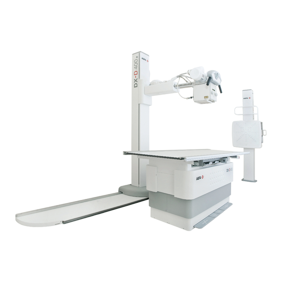
12 | DX-D 400 | Introduction to DX-D 400 Configuration DX-D 400 is a configurable DR (Direct Radiography X-Ray system), CR (Computed Radiography) or film/screen X-ray system. The complete DX-D 400 consists of the following components: • Floor mounted tube stand •... - Page 13 DX-D 400 | Introduction to DX-D 400 | 13 The DX-D Software Console is available on the NX workstation, to synchronize the X-ray exposure parameters between the NX application and the generator. DR Generator Sync Box NX workstation Floor mounted tube stand...
-
Page 14: Equipment Classification
14 | DX-D 400 | Introduction to DX-D 400 Equipment Classification Per EN/IEC60601-1, Medical Electrical Equipment, General Requirements for Safety 3rd Edition, this device is classified as following: Table 1: Equipment classification Class I equipment Equipment in which protection against electric... -
Page 15: Options And Accessories
Anti-scatter grids are used to reduce scattered radiation and improve image quality. Grids are available as an option. Refer to the Agfa website for specifications on the anti-scatter grids that have been found compatible with the system and the DR Detectors. -
Page 16: Operation Controls
16 | DX-D 400 | Introduction to DX-D 400 Operation Controls Refer to the DX-D 400 X-Ray System User Manual (document 0232) for a description of the Touchscreen Console, the Overlay Console, the collimator controls, the RAD Table controls and the RAD Wall Stand controls. -
Page 17: Nx Application On The Nx Workstation
DX-D 400 | Introduction to DX-D 400 | 17 NX Application on the NX Workstation The NX application is used to define patient information, select exposures and process images. Figure 2: NX application The operation of the NX application is described in the NX User Manual, document 4420.. -
Page 18: Dr Software Console
18 | DX-D 400 | Introduction to DX-D 400 DR Software Console The DR Software Console is available to support X-ray exposure parameter control on the NX workstation. It is displayed on the NX workstation next to the NX application. -
Page 19: Dr Detector Switch
DX-D 400 | Introduction to DX-D 400 | 19 DR Detector Switch The DR Detector Switch shows which DR Detector is active and shows its status. The DR Detector Switch can be used to activate another DR Detector. The DR Detector Switch can also be used to switch to CR for making an exposure on a cassette. -
Page 20: Exposure Button
20 | DX-D 400 | Introduction to DX-D 400 Exposure button Preparing for exposure Press the exposure button down to the first pressure point and hold it for approximately 0.5 s to 2 s. The X-ray tube is prepared for performing an exposure. -
Page 21: Portable Dr Detector
DX-D 400 | Introduction to DX-D 400 | 21 Portable DR Detector When performing an exposure, keep in mind the following detector orientation aids: 1. Tube side 2. Patient orientation marker For an overview of the operation controls of the DR Detector, refer to the user manual of the DR Detector. -
Page 22: System Documentation
22 | DX-D 400 | Introduction to DX-D 400 System Documentation The documentation shall be kept with the system for easy reference. The most extensive configuration is described within this manual, including the maximum number of options and accessories. Not every function, option or accessory described may have been purchased or licensed on a particular piece of equipment. -
Page 23: Training
DX-D 400 | Introduction to DX-D 400 | 23 Training The user must have received adequate training on the safe and effective use of the system before attempting to work with it. Training requirements may vary from country to country. The user must make sure that training is received in accordance with local laws or regulations that have the force of law. -
Page 24: Product Complaints
Manufacturer address: Agfa Service Support - local support addresses and phone numbers are listed on www.agfa.com Agfa - Septestraat 27, 2640 Mortsel, Belgium Agfa - Fax +32 3 444 7094... -
Page 25: Compatibility
Compatibility The system must only be used in combination with other equipment or components if these are expressly recognized by Agfa as compatible. A list of such equipment and components is available from Agfa service on request. Changes or additions to the equipment must only be carried out by persons authorized to do so by Agfa. -
Page 26: Compliance
26 | DX-D 400 | Introduction to DX-D 400 Compliance The system is compliant with specific directives and standards. Topics: • General • Safety • X-Ray Safety • Electromagnetic Compatibility 0230D EN 20191209 1135... -
Page 27: General
DX-D 400 | Introduction to DX-D 400 | 27 General • The product has been designed in accordance with the MEDDEV Guidelines relating to the application of Medical Devices and have been tested as part of the conformity assessment procedures required by 93/42/EEC Medical Device Directive (European Council Directive 93/42/EEC on Medical Devices). -
Page 28: Connectivity
28 | DX-D 400 | Introduction to DX-D 400 Connectivity On configurations with X-ray exposure parameter control on the NX workstation, the NX workstation is connected to the X-ray system to exchange X-ray exposure parameters. Note: The connections between the components of the system should not be disconnected or modified. -
Page 29: Installation
DX-D 400 | Introduction to DX-D 400 | 29 Installation Installation and configuration is performed by an Agfa trained and authorized service engineer. Contact your local support organization for more information. On a configuration with multiple DR Detectors of the same type, it is required to apply labeling to the DR Detector containing a unique nickname for each DR Detector. -
Page 30: Messages
30 | DX-D 400 | Introduction to DX-D 400 Messages Under certain conditions the system shows a dialog box in the middle of the screen containing a message, or a message is displayed in a fixed message area in the user interface. This message informs the user that either a problem has occurred or that a requested action cannot be performed. -
Page 31: Labels
DX-D 400 | Introduction to DX-D 400 | 31 Labels Mark Meaning This mark shows compliance of the equipment with Directive 93/42/EEC (for European Union). This mark indicates that this is a Type B Equipment Serial number Manufacturer Date of manufacture... - Page 32 32 | DX-D 400 | Introduction to DX-D 400 • Labeling of the DR Generator Sync Box 0230D EN 20191209 1135...
-
Page 33: Dr Detector Identification Label
DX-D 400 | Introduction to DX-D 400 | 33 DR Detector identification label Label Meaning Writable label to identify and dedicate a DR Detector to an X- ray system bucky. 0230D EN 20191209 1135... -
Page 34: Type Label
34 | DX-D 400 | Introduction to DX-D 400 Type label Mark Meaning Type label positioned on the column. The type label information for each combi- nation of X-ray tube and X-ray generator is available in the technical data. (Sample of subtype 5420/100) The 21 CFR Subchapter J label is positioned close to the type label. -
Page 35: Additional Labeling Of The X-Ray Generator Control Box
DX-D 400 | Introduction to DX-D 400 | 35 Additional Labeling of the X-Ray Generator Control Box Following warning is printed on the X-ray generator control box in English: Warning: This x-ray unit may be dangerous to patient and operator unless safe exposure factors, operating instructions and maintenance schedules are observed. -
Page 36: Labeling Of The Dr Generator Sync Box
36 | DX-D 400 | Introduction to DX-D 400 Labeling of the DR Generator Sync Box The type label is located on the DR Genera- tor Sync Box Figure 4: Example of type label Functional earth Medical equipotential 0230D EN 20191209 1135... -
Page 37: Cleaning And Disinfecting
DX-D 400 | Introduction to DX-D 400 | 37 Cleaning and Disinfecting All appropriate policies and procedures should be followed to avoid contamination of the staff, patients and equipment. All existing universal precautions should be extended to avoid potential contaminations and to avoid patients coming into (close) contact with the device. -
Page 38: Cleaning
38 | DX-D 400 | Introduction to DX-D 400 Cleaning To clean the exterior of the equipment: 1. Stop the system Warning: When the equipment is going to be cleaned, be sure to turn OFF the power of each device, and to unplug the power cord from the AC outlet. -
Page 39: Disinfecting
If you plan to use other disinfectants, approval of Agfa is needed before use, as most disinfectants can damage the device. UV disinfection is also not allowed. Perform the procedure following the instructions for use, the disposal instructions and the safety instructions of the selected disinfectants and tools and of the hospital. -
Page 40: Approved Disinfectants
40 | DX-D 400 | Introduction to DX-D 400 Approved disinfectants Refer to the Agfa website for specifications on the disinfectants that have been found compatible with the cover material of the device and can be used on the outer surface of the device. -
Page 41: Patient Data Security
DX-D 400 | Introduction to DX-D 400 | 41 Patient data security The user must ensure that the patients’ legal requirements are met and that the security of the patient data is guarded. The user must define who can access patient data in which situations. -
Page 42: Maintenance
The DR Detector requires regular calibration. Calibration instructions are described in the DR Detector Calibration Key User Manual (doc 0134). Maintenance procedures Maintenance procedures for the X-ray system are described in the DX-D 400 Owner’s Manual. 0230D EN 20191209 1135... -
Page 43: Environmental Protection
DX-D 400 | Introduction to DX-D 400 | 43 Environmental protection Figure 5: WEEE symbol Figure 6: Battery symbol WEEE end user notice The directive on Waste Electrical and Electronic Equipment (WEEE) aims to prevent the generation of electric and electronic waste and to promote the reuse, recycling and other forms of recovery. -
Page 44: Safety Directions
44 | DX-D 400 | Introduction to DX-D 400 Safety Directions Warning: Only qualified and authorized personnel shall operate this system. In this context ‘qualified’ means those persons legally permitted to operate this equipment in the jurisdiction in which the equipment is being used, and ‘authorized’... - Page 45 DX-D 400 | Introduction to DX-D 400 | 45 Warning: Avoid unnecessary dose by checking the workstation selection on the X-ray generator console before exposing. In a configuration with a DR Detector configured on a virtual port, the DR Detector will not be triggered if a free exposure is selected on the Generator console and yet the exposure will be allowed.
- Page 46 46 | DX-D 400 | Introduction to DX-D 400 Caution: To avoid images being lost due to a power failure, the workstation and the digitizer have to be connected to an uninterruptable power supply (UPS) or an institutional standby generator.
-
Page 47: Getting Started
DX-D 400 | Getting started | 47 Getting started Topics: • Starting the System • Performing an exposure using the DR Detector • Performing an exposure using a CR cassette • Stopping the System 0230D EN 20191209 1135... -
Page 48: Starting The System
48 | DX-D 400 | Getting started Starting the System Allow the DR Detector to warm up before the system is used for clinical purposes. The warming-up time starts as soon as the DR Detector has been powered on and the NX workstation is running. To check if a warming-up time is required, refer to the DR Detector technical data. -
Page 49: Performing An Exposure Using The Dr Detector
DX-D 400 | Getting started | 49 Performing an exposure using the DR Detector Topics: • Step 1: retrieve the patient info • Step 2: select the exposure • Step 3: prepare the exposure • Step 4: check the exposure settings •... -
Page 50: Step 1: Retrieve The Patient Info
50 | DX-D 400 | Getting started Step 1: retrieve the patient info At the NX workstation: 1. When a new patient comes in, define the patient info for the exam. 2. Start the exam. 0230D EN 20191209 1135... -
Page 51: Step 2: Select The Exposure
DX-D 400 | Getting started | 51 Step 2: select the exposure In the operator room: 1. At the NX workstation, select the thumbnail for the exposure in the Image Overview pane of the Examination window. The selected DR Detector is activated. -
Page 52: Step 3: Prepare The Exposure
52 | DX-D 400 | Getting started Step 3: prepare the exposure In the examination room: 1. Position the DR Detector. When using the bucky, check that the identification labels on the DR Detector and on the bucky match. Do not use a DR Detector that is dedicated to another bucky. -
Page 53: Step 4: Check The Exposure Settings
DX-D 400 | Getting started | 53 Step 4: check the exposure settings Related Links DR Detector Status on page 19 On the DR Detector Switch: 1. Check if the DR Detector Switch displays the name of the DR Detector that's being used 2. -
Page 54: Step 5: Execute The Exposure
54 | DX-D 400 | Getting started Step 5: execute the exposure In the operator room: Press the exposure button to execute the exposure. Instruction: Make sure the generator is ready for exposure before you press the exposure button. Warning: The radiation indicator on the control console lights up during exposure release. -
Page 55: Step 6: Perform A Quality Control
DX-D 400 | Getting started | 55 Step 6: perform a quality control At the NX workstation: 1. Select the image on which quality control is to be performed. 2. Prepare the image for diagnosis by using e.g. L/R markers or annotations. -
Page 56: Performing An Exposure Using A Cr Cassette
56 | DX-D 400 | Getting started Performing an exposure using a CR cassette Note: Using an ID Tablet to identify cassettes before the exposure will break the communication of X-ray parameters between the NX workstation and the X-ray generator console. It is advised to identify cassettes after the exposure, as described in this workflow. -
Page 57: Step 1: Retrieve The Patient Info
DX-D 400 | Getting started | 57 Step 1: retrieve the patient info At the NX workstation: 1. When a new patient comes in, define the patient info for the exam. 2. Start the exam. 0230D EN 20191209 1135... -
Page 58: Step 2: Select The Exposure
58 | DX-D 400 | Getting started Step 2: select the exposure In the operator room at the NX workstation: 1. Select the thumbnail for the exposure in the Image Overview pane of the Examination window. RAD Table DR with cassette in the DR bucky... -
Page 59: Step 3: Prepare The Exposure
DX-D 400 | Getting started | 59 Step 3: prepare the exposure In the examination room: 1. Position the cassette. Note: For a free exposure, partial lead covering of the cassette may be required if multiple images are taken on one cassette. -
Page 60: Step 4: Check The Exposure Settings
60 | DX-D 400 | Getting started Step 4: check the exposure settings In the operator room at the X-ray generator console or on the DX-D Software Console: 1. Check if the exposure settings displayed on the console are suitable for the exposure. -
Page 61: Step 5: Execute The Exposure
DX-D 400 | Getting started | 61 Step 5: execute the exposure In the operator room: Press the exposure button to execute the exposure. Warning: The radiation indicator on the software console lights up during exposure release. • On configurations with integration of X-ray exposure parameters, the actual X-Ray exposure parameters are sent back from the console to the NX workstation and are shown in the Image Detail pane. -
Page 62: Step 6: Repeat Steps 2 To 5 For The Next Subexposures
62 | DX-D 400 | Getting started Step 6: repeat steps 2 to 5 for the next subexposures 0230D EN 20191209 1135... -
Page 63: Step 7: Digitize The Image
DX-D 400 | Getting started | 63 Step 7: digitize the image In the examination room: Take the exposed cassette. In the operator room: 1. Insert the cassette in the digitizer. 2. Click ID in the examination window of NX. -
Page 64: Step 8: Perform A Quality Control
64 | DX-D 400 | Getting started Step 8: perform a quality control In the operator room at the NX workstation: 1. Select the image on which quality control is to be performed. 2. Prepare the image for diagnosis by using e.g. L/R markers or annotations. -
Page 65: Stopping The System
DX-D 400 | Getting started | 65 Stopping the System To stop the system: 1. Stop the NX workstation. NX can be stopped in two ways, either by logging out of Windows or without logging out of Windows. For detailed information on stopping NX, refer to the NX User Manual, document 4420. -
Page 66: Problem Solving
66 | DX-D 400 | Problem solving Problem solving Topics: • NX receives black or underexposed DR image due to repeatedly pushing the exposure button • NX receives black DR image when X-ray system not ready for exposure • Wrong modality position selected •... -
Page 67: Nx Receives Black Or Underexposed Dr Image Due To Repeatedly Pushing The Exposure Button
DX-D 400 | Problem solving | 67 NX receives black or underexposed DR image due to repeatedly pushing the exposure button Details A black or underexposed image is arriving on the NX workstation. Cause The exposure button was pushed to the first pressure point and released without making an exposure. -
Page 68: Nx Receives Black Dr Image When X-Ray System Not Ready For Exposure
68 | DX-D 400 | Problem solving NX receives black DR image when X-ray system not ready for exposure Details A black image is arriving on the NX workstation. Cause On a system without DR Software Console, the expo- sure button was pushed while the X-ray system was not ready for exposure. -
Page 69: Wrong Modality Position Selected
DX-D 400 | Problem solving | 69 Wrong modality position selected Details The active modality position on the X-ray system does not match the selected modality position on the NX Workstation. Cause The modality position has been modified on the gener- ator console. -
Page 70: Panel Status Remains In Error
70 | DX-D 400 | Problem solving Panel status remains in error Details The panel status remains in error. Cause The generator is in error state. This situation applies only to Siemens generators. Brief Solution Restart the generator. 0230D EN 20191209 1135... -
Page 71: Error E32 Displayed On Dx-D Software Console After Preparing For Exposure
Click the OK button on the DX-D Software Console or the Reset button on the DX-D 400 Touchscreen Console or on the DX-D 400 overlay console until the error indi- cation disappears on the console. If the equipment remains inoperative, try restarting the generator or call service. -
Page 72: Error E38, E39 Or E40 Displayed On The Console After Preparing For Exposure
Click the OK button on the DX-D Software Console or the Reset button on the DX-D 400 Touchscreen Console or on the DX-D 400 overlay console until the error indi- cation disappears on the console. If the equipment remains inoperative, try restarting the generator or call service. -
Page 73: Technical Data
DX-D 400 | Technical Data | 73 Technical Data Topics: • DX-D 400 X-Ray System Technical Data • Fixed DR Detector Technical Data • Portable DR Detector Technical Data • DR Generator Sync Box Technical Data • NX Workstation Technical Data... -
Page 74: Dx-D 400 X-Ray System Technical Data
74 | DX-D 400 | Technical Data DX-D 400 X-Ray System Technical Data Refer to the DX-D 400 X-Ray System User Manual (document 0232) for technical data of the X-Ray system. For overall system environmental conditions, the environmental conditions of the portable DR detector should be taken into account. -
Page 75: Fixed Dr Detector Technical Data
DX-D 400 | Technical Data | 75 Fixed DR Detector Technical Data Manufacturer Manufacturer DR Detector Varex Imaging Corporation, 1678 So. Pioneer Rd, Salt Lake City, UT 84104, USA Supported models 4343R (part number 7965) CsI conversion screen 4343R (part number 7964) - Page 76 76 | DX-D 400 | Technical Data Reliability Estimated product life (if regularly serviced 100 000 RAD and maintained according to Agfa instruc- tions) 0230D EN 20191209 1135...
-
Page 77: Portable Dr Detector Technical Data
DX-D 400 | Technical Data | 77 Portable DR Detector Technical Data Refer to the DR Detector User Manual. 0230D EN 20191209 1135... -
Page 78: Dr Generator Sync Box Technical Data
78 | DX-D 400 | Technical Data DR Generator Sync Box Technical Data Model name DR Generator Sync Box Type number 5400/516 Labeling Dimensions Depth 21.5 cm Width 33.5 cm Height 6.5 cm Weight 3.2 kg Electrical connection 100-240 V AC, 50/60 Hz Power consumption 40 W (max. -
Page 79: Nx Workstation Technical Data
DX-D 400 | Technical Data | 79 NX Workstation Technical Data Electrical connection Operating voltage 90 – 263VAC Mains fuse protection 5.5A Mains frequency 47 – 63 Hz Power consumption Maximum power consumption 320W 0230D EN 20191209 1135... -
Page 80: Technical Documentation
80 | DX-D 400 | Technical Documentation Technical Documentation This appendix contains technical information. It is only available in English. Remarks for HF-emission and immunity Warning: This device is intended for use by healthcare professionals only. This device may cause radio interference or may disrupt the operation of nearby equipment. - Page 81 DX-D 400 | Technical Documentation | 81 Note: In accordance with Standard IEC 61601-1-2, the emissions character- istics of this equipment make it suitable for use in industrial areas and hospi- tals (CISPR 11 Class A. If it is used in a residential environment (for which CISPR 11 Class B is normally required) this equipment might not offer ade- quate protection to radio-frequency communication services.
- Page 82 82 | DX-D 400 | Technical Documentation < 5% U > 95% ly, even when the energy (> 95% dip in for 250 supply is interrupted, it is ) for 250 cy- periods recommended to use an en- cles ergy supply free of inter- ruptions or a battery.
- Page 83 DX-D 400 | Technical Documentation | 83 Recommended separation dis- tance d = 1.2 d = 1.2 MHz to 800 MHz d = 2.3 MHz to 2.5 GHz where ’P’ is the maximum output power rating of the transmitter in...
- Page 84 84 | DX-D 400 | Technical Documentation • REMARK 2: These Guidelines may not apply to all situations. The disper- sion of electromagnetic waves is influenced by absorption and reflec- tions from buildings, objects and people. The field strength of stationary transmitters, such as base stations of radio telephones, mobile broadcasts for rural areas, amateur stations, and AM and FM radio transmitters, cannot be precisely predetermined theoretically.
- Page 85 DX-D 400 | Technical Documentation | 85 TYPICAL RF DEVICES (Worst-Case scenario) Device: Power @ Frequency Recommended distance(m) GMRS device (Professional Walkie-Talkie): 5 W @ 462-467 MHz GSM / UMTS cell phone: 2 W @ 850/1700/1900 MHz FRS device (Amateur Walkie-Talkie): 500 mW @...
Need help?
Do you have a question about the DX-D 400 and is the answer not in the manual?
Questions and answers