Table of Contents
Advertisement
Quick Links
Advertisement
Table of Contents

Related Manuals for AGFA DX-D 300


Summary of Contents for AGFA DX-D 300
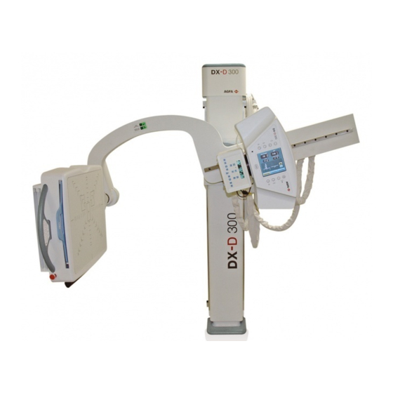
- Page 1 DX-D 300 U-Arm User Manual Technical Publication 0171F EN 20181009...
- Page 3 DX-D 300 U-Arm User Manual REVISION HISTORY REVISION DATE REASON FOR CHANGE FEB 03, 2010 First edition APR 05, 2010 Added Patient Handle option SEP 30, 2011 Removed U-Arm Software Console information AUG 01, 2013 IEC Standards update APR 27, 2015 New Handle and Receptor Overlay.
- Page 4 DX-D 300 U-Arm User Manual ADVISORY SYMBOLS The following advisory symbols will be used throughout this manual. Their application and meaning are described below. DANGERS ADVISE OF CONDITIONS OR SITUATIONS THAT IF NOT HEEDED OR AVOIDED WILL CAUSE SERIOUS PERSONAL INJURY OR DEATH.
-
Page 5: Table Of Contents
DX-D 300 U-Arm User Manual TABLE OF CONTENTS Section Page INTRODUCTION ............ -
Page 6: Section Page
DX-D 300 U-Arm User Manual Section Page Electromagnetic Compatibility (EMC) ........ - Page 7 DX-D 300 U-Arm User Manual Section Page OPERATING SEQUENCES ..........
- Page 8 DX-D 300 U-Arm User Manual 0171F EN 20181009...
-
Page 9: Introduction
INTRODUCTION This manual contains all the necessary information to understand and operate the DX-D 300 U-Arm. It provides a general description, safety information, operating instructions and specifications concerning the equipment. This manual is not intended to teach radiology or to make any type of clinical diagnosis. -
Page 10: General Features
DX-D 300 U-Arm User Manual The Generator Cabinet comprises the Power Module (which contains the power and control components) and the High Voltage Transformer. The operator controls and displays for radiographic operations are shown on the U-Arm Touch Screen and on the Software Console of the NX Workstation. -
Page 11: Options
DX-D 300 U-Arm User Manual The main features of the Generator are: Constant potential high frequency. Three point control by selecting kVp, mA and ms, two point control by selecting kVp and mAs (no AEC), or one point control by selecting kVp with AEC operations. - Page 12 DX-D 300 U-Arm User Manual Illustration 1-2 Identification Labels Control Box U-Arm Label at bottom right side Laminated Table (Optional) Carbon Fibre Table (Optional) 0171F EN 20181009...
-
Page 13: Indications For Use
INTENDED USE This equipment is intended for use by qualified personnel only. The DX-D 300 U-Arm is an equipment included in a Medical Equipment System designed for general radiography in hospitals, clinics and medical practices to provide X-ray radiographic images of the skeleton, skull, chest, abdomen, extremities and other body parts for diagnosis. -
Page 14: Applied Parts
DX-D 300 U-Arm User Manual APPLIED PARTS Applied Parts refer to parts of the medical equipment that in Normal Use necessarily comes into physical contact with the patient for the medical equipment to perform its function. This RAD equipment includes the following Applied Parts: Tabletop of the Radiographic Mobile Table. -
Page 15: Safety And Regulatory Information
DX-D 300 U-Arm User Manual SECTION 2 SAFETY AND REGULATORY INFORMATION This section describes the safety considerations, general precautions for patient, operator and equipment in order to perform a safe operation and service tasks. Regulatory Information and symbols used in the equipment are detailed in this section to operate it safely. - Page 16 DX-D 300 U-Arm User Manual OPERATOR AND SERVICE PERSONNEL AUTHORIZED TO USE, INSTALL, CALIBRATE MAINTAIN THIS EQUIPMENT MUST BE AWARE OF THE DANGER OF EXCESSIVE EXPOSURE TO X-RAY RADIATION. IT IS VITALLY IMPORTANT THAT EVERYONE WORKING WITH X-RAY RADIATION IS PROPERLY TRAINED, INFORMED ON THE HAZARDS OF RADIATION AND TAKE ADEQUATE STEPS TO ENSURE PROTECTION AGAINST INJURY.
- Page 17 DX-D 300 U-Arm User Manual SPECIAL ATTENTION MUST BE GIVEN TO DIAGNOSTIC X-RAY EQUIPMENT SPECIFIED USED COMBINATION WITH ACCESSORIES OR OTHER ITEMS. BE AWARE OF POSSIBLE ADVERSE EFFECT ARISING FROM THESE MATERIALS LOCATED IN THE X- -RAY BEAM. (SEE THE TABLE BELOW FOR THE MAXIMUM EQUIVALENT ATTENUATION OF MATERIALS POSSIBLY LOCATED IN THE X-RAY BEAM).
-
Page 18: Responsibilities
DX-D 300 U-Arm User Manual RESPONSIBILITIES THIS X-RAY UNIT MAY BE DANGEROUS TO PATIENT AND OPERATOR UNLESS SAFE EXPOSURE FACTORS, OPERATING INSTRUCTIONS MAINTENANCE SCHEDULES ARE OBSERVED. THE EQUIPMENT HEREIN DESCRIBED IS SOLD WITH THE UNDERSTANDING THAT MANUFACTURER, AGENTS, AND REPRESENTATIVES ARE NOT LIABLE FOR... -
Page 19: Maximum Permissible Dose (Mpd)
DX-D 300 U-Arm User Manual IT IS THE RESPONSIBILITY OF THE PURCHASER / CUSTOMER TO PROVIDE THE MEANS FOR AUDIO AND VISUAL COMMUNICATION BETWEEN THE OPERATOR AND THE PATIENT. IT IS THE RESPONSIBILITY OF THE OPERATOR TO ENSURE THAT ALL THE EXPOSURE PARAMETERS ARE CORRECT... -
Page 20: Radiation Protection
DX-D 300 U-Arm User Manual RADIATION PROTECTION Although this equipment is built to the highest safety standards and incorporates a high degree of protection against X-radiation other than the useful beam, no practical design of equipment can provide complete protection,... - Page 21 DX-D 300 U-Arm User Manual Observe the following rules for radiation protection of the personnel in the examination room during X-ray exposures: - Wear radiation protective clothing. - Wear a personal dosemeter. - Use the different recommended protective materials and devices against radiation.
-
Page 22: Monitoring Of Personnel
DX-D 300 U-Arm User Manual MONITORING OF PERSONNEL Monitoring of personnel to determine the amount of radiation to which they have been exposed provides a valuable cross check to determine whether or not safety measures are adequate. It may reveal inadequate or improper radiation protection practices and potentially serious radiation exposure situations. - Page 23 DX-D 300 U-Arm User Manual General Mandatory action. Type B applied part. Protection against harmful ingress of water or particulate matter. IP Classification: Ordinary. Ionizing radiation. Non-ionizing electromagnetic radiation. Radiation of Laser apparatus. Do not stare into beam. (Only applicable to equipment with Laser Pointer) Dangerous voltage.
- Page 24 DX-D 300 U-Arm User Manual Warning: Non-ionizing radiation. Warning: Laser beam. Warning: Dangerous voltage. Warning: Do not place fingers between mobile and fixed parts of the equipment, it may cause serious injuries to patient or operator. As well, make sure the patient extremities are correctly positioned into limit areas during operation, movement of parts may cause serious damages to patient.
- Page 25 DX-D 300 U-Arm User Manual Stop (of action). Emergency stop. “ON” power. “OFF” power. “ON” / “OFF” (push-push). Each position, “ON” or “OFF”, is a stable position. Alternating current. Three-phase alternating current. Three-phase alternating current with neutral conductor. Connection point for the neutral conductor on Permanently Installed equipment.
- Page 26 DX-D 300 U-Arm User Manual Direct current. Both direct and alternating current. Protective Earth (Ground). Earth (Ground). This symbol according to the European Directive indicates that the Waste of Electrical and Electronic Equipment (WEEE) must not be disposed of as unsorted municipal waste and must be collected separately.
-
Page 27: Regulatory Information
DX-D 300 U-Arm User Manual REGULATORY INFORMATION 2.7.1 CERTIFICATIONS The DX- D300 U-Arm covered by this Operation Manual is authorized to be marked with CE MARKING in accordance with the provisions of the Council Directive 93 / 42 / EEC as amended by 2007/47/EC concerning Medical Devices. -
Page 28: Protection Against Electric Shock Hazards
DX-D 300 U-Arm User Manual 2.7.4 PROTECTION AGAINST ELECTRIC SHOCK HAZARDS Protection against electric shock hazards in accordance with Standards: IEC 60601--1:1988, 2005 2012, IEC 60601--2--7:1998, IEC 60601--2--54:2009 and 2015. This equipment has been classified as a type-B ( ) device, in accordance with Standard IEC 60601-1 requirements. -
Page 29: Protection Against Hazards From Unwanted Or Excessive Radiation . 20 2.7.8 Designated Significant Zones Of Occupancy
DX-D 300 U-Arm User Manual 2.7.8 DESIGNATED SIGNIFICANT ZONES OF OCCUPANCY X-ray equipment specified for examinations that do not need the operator or staff to be close to the patient during normal use shall be provided with means to allow the following control functions from a “Protected Area” (refer to illustration below): Selection and control of modes of operation. - Page 30 DX-D 300 U-Arm User Manual X-Ray equipment specified for any radiological examination that requires the operator or staff to be close to the patient during normal use (e.g. some pediatric examinations or other types of examinations for patients that may require assistance), shall have at least one “Significant Zone of Occupancy”...
- Page 31 DX-D 300 U-Arm User Manual Illustration 2-2 Radiographic Examination in Undertable Position (Receptor in Horizontal Position) X-RAY TUBE Focal Spot Phantom Patient Support X- -Ray Receptor S = SIGNIFICANT ZONE OF OCCUPANCY MINIMUM AREA 60 x 60 cm MINIMUM HEIGHT ABOVE THE FLOOR 200 cm...
-
Page 32: Distribution Of Stray Radiation
DX-D 300 U-Arm User Manual 2.7.9 DISTRIBUTION OF STRAY RADIATION Measurement conditions to determine the distribution of Stray Radiation in the Significant Zone of Occupancy are in accordance with IEC 60601--1--3:1994, 2008 and 2013. Exposure Parameters: RAD mode, 150 kVp, 20 mAs. - Page 33 DX-D 300 U-Arm User Manual Illustration 2-3 Distribution of Stray Radiation (S1) with the Receptor inThorax Position. 500 1000 1500 2000 2500 3000 3500 4000 4500 5000 5500 6000 6500 7000 7500 8000 8500 9000 9500 10000 STRAY RADIATION (μGy/h)
- Page 34 DX-D 300 U-Arm User Manual Illustration 2-4 Distribution of Stray Radiation (S2) with the Receptor in Undertable Position. 2000 4000 6000 8000 10000 12000 14000 STRAY RADIATION (μGy/h) d = 50 cm d = 100 cm SIGNIFICANT ZONE OF OCCUPANCY...
- Page 35 DX-D 300 U-Arm User Manual Illustration 2-5 Distribution of Stray Radiation (S3) with the Receptor in Undertable Position. 2000 4000 6000 8000 10000 12000 14000 d = 50 cm STRAY RADIATION (μGy/h) d = 100 cm SIGNIFICANT ZONE OF OCCUPANCY...
- Page 36 DX-D 300 U-Arm User Manual Illustration 2-6 Distribution of Stray Radiation (S4) with the Receptor in Undertable Position. 2000 4000 6000 8000 10000 12000 14000 16000 18000 d = 50 cm STRAY RADIATION (μGy/h) d = 100 cm SIGNIFICANT ZONE OF OCCUPANCY...
- Page 37 DX-D 300 U-Arm User Manual ELECTROMAGNETIC COMPATIBILITY (EMC) This equipment generates, uses, and can radiate radio frequency energy. The equipment may cause radio frequency interference to other medical or non medical devices and to radio communications. To provide reasonable protection against such interference, this equipment complies with emissions limits for a Group 1 -- Class A Medical Devices Directive as stated in IEC 60601--1--2: 2007 and 2014.
- Page 38 DX-D 300 U-Arm User Manual It is customer responsibility to assure that this equipment and vicinity equipment complies the value of radio frequency interferences shown in General Regulation for safety according to IEC 60601-1-2: 2007 and 2014 Tables as described in this section.
- Page 39 DX-D 300 U-Arm User Manual GUIDANCE AND MANUFACTURER’S DECLARATION - - ELECTROMAGNETIC IMMUNITY (IEC 60601-1-2:2007) The Radiographic Room DX-D300 is intended for use in the electromagnetic environment specified below. The customer or the user of this Radiographic Room DX-D300 should assure that it is used in such an environment.
- Page 40 DX-D 300 U-Arm User Manual GUIDANCE AND MANUFACTURER’S DECLARATION - ELECTROMAGNETIC IMMUNITY (IEC 60601-1-2:2007) The Radiographic Room DX-D300is intended for use in an electromagnetic environment specified below. The customer or Operator of thisRadiographic Room DX-D300 should assure that it is used in such an environment.
- Page 41 DX-D 300 U-Arm User Manual RECOMMENDED SEPARATION DISTANCES BETWEEN PORTABLE AND MOBILE RF COMMUNICATIONS EQUIPMENT AND THE X-RAY SYSTEM (IEC 61601-1-2:2007) The Radiographic Room DX-D300 is intended for use in an electromagnetic environment in which radiated RF disturbances are controlled. The customer or the user of this Radiographic Room DX-D300 can help prevent electromagnetic interference by maintaining a minimum distance between portable and mobile RF communications equipment (transmitters) and the X-ray System as recommended below, according to the maximum output power of the communications equipment.
- Page 42 DX-D 300 U-Arm User Manual GUIDANCE AND MANUFACTURER’S DECLARATION - ELECTROMAGNETIC IMMUNITY (IEC 61601-1-2:2014) The Radiographic Room DX-D300 is intended for use in the electromagnetic environment specified below. The customer or Operator of this Radiographic Room DX-D300 should assure that it is used in such an environment.
- Page 43 DX-D 300 U-Arm User Manual GUIDANCE AND MANUFACTURER’S DECLARATION - ELECTROMAGNETIC IMMUNITY (IEC 60601-1-2:2014) The Radiographic Room DX-D300 is intended for use in an electromagnetic environment specified below. The customer or Operator of thisRadiographic Room DX-D300 should assure that it is used in such an environment.
- Page 44 DX-D 300 U-Arm User Manual IMMUNITY REQUIREMENTS TO RF WIRELESS COMMUNICATIONS EQUIPMENT (IEC 60601-1-2:2014) The Radiographic Room DX-D300 is intended for use in an electromagnetic environment specified below. The customer or Operator of this Radiographic Room DX-D300 should assure that it is used in such an environment.
- Page 45 DX-D 300 U-Arm User Manual QUANTITATIVE INFORMATION The following tables show the Quantitative Information associated Note to this equipment according to the Standard IEC 60601- -1- -3:2008 + AMD1:2013. These tables illustrate loading factors for image performance and supply Dose indication examples. Therefore,...
- Page 46 DX-D 300 U-Arm User Manual Quantitative Information Loading Factors Parameter Selection Filtrat. Measured Doses 0.012 Small 0.016 0.025 7.479 10.795 0.036 Small 0.087 0.136 4.906 7.682 0.213 13 13 13x13 Large 0.836 1.307 9.407 14.125 1.962 Large 3.073 4.802 17.286 23.863...
- Page 47 DX-D 300 U-Arm User Manual Quantitative Information Loading Factors Parameter Selection Filtrat. Measured Doses 0.012 Small 0.046 0.072 21.746 113.713 0.379 Small 0.252 0.394 14.195 79.388 2.205 13 13 13x13 Large 39.4 2.587 4.042 29.103 157.649 21.896 Large 191.4 10.009 15.639...
- Page 48 DX-D 300 U-Arm User Manual Quantitative Information Loading Factors Parameter Selection Filtrat. Measured Doses 0.012 Small 0.087 0.136 40.753 378.000 1.260 Small 0.461 0.702 25.909 256.070 7.113 13 13 13x13 Large 74.5 4.674 7.303 52.582 511.763 71.078 Large 366.7 18.374 28.709...
- Page 49 DX-D 300 U-Arm User Manual Quantitative Information Loading Factors Parameter Selection Filtrat. Measured Doses 0.012 Small 0.131 0.205 61.550 854.348 2.848 Large 11.2 0.698 1.091 39.282 562.852 15.635 13 13 13x13 Large 7.136 11.149 80.276 1132.591 157.304 Large 448.9 28.400 44.375...
- Page 50 DX-D 300 U-Arm User Manual Quantitative Information Loading Factors Parameter Selection Filtrat. Measured Doses 0.012 Small 0.194 0.303 90.897 1611.652 5.372 Large 19.1 1.037 1.620 58.304 7.682 0.213 13 13 13x13 Large 164.1 10.722 16.753 120.620 2195.061 304.870 Large 823.7 43.078...
- Page 51 DX-D 300 U-Arm User Manual Quantitative Information Loading Factors Parameter Selection Filtrat. Measured Doses 0.012 Small 0.253 0.395 118.573 2493.391 8.311 Large 24.4 1.375 2.148 77.331 1679.791 46.661 13 13 13x13 Large 239.3 14.530 22.704 163.467 3508.591 487.304 Large 882.9 59.548...
- Page 52 Agfa. If the device malfunctions and may have caused or contributed to a serious injury of a patient, Agfa must be notified immediately by telephone, fax or written correspondence to the following address: Agfa Service Support - local support addresses and phone numbers are listed on www.agfa.com...
- Page 53 DX-D 300 U-Arm User Manual SECTION 3 START UP AND SHUTDOWN START UP The System should be powered by the same Room Electrical Cabinet where the X-ray Generator is connected, that is, the whole System will be powered from the same Electrical Cabinet.
- Page 54 DX-D 300 U-Arm User Manual The Control Box is provided also with an Emergency-OFF Switch that cuts the power supply to the Unit. Once pressed, wait one minute before turning ON the Unit again. IN THE EVENT OF AN EMERGENCY FORCIBLY DEPRESS THE X-RAY ROOM “EMERGENCY OFF SWITCH”...
- Page 55 DX-D 300 U-Arm User Manual SHUTDOWN ROUTINE To turn the System OFF: Turn OFF the NX Workstation. Press ON/OFF Switch located at the Control Box Door (the Emergency Stop not activated) the Green lamp turns OFF. Press the X-Ray Control OFF Button, the Green lamp turns OFF.
- Page 56 DX-D 300 U-Arm User Manual This page intentionally left blank. 0171F EN 20181009...
- Page 57 DX-D 300 U-Arm User Manual SECTION 4 OPERATION OF THE U-ARM The Control Panel comprises the Touch Screen and the Control buttons with their corresponding symbols. The Movement Buttons on the Control Panel are duplicated on the DR Detector Assembly Handle.
- Page 58 DX-D 300 U-Arm User Manual SYSTEMS MOVEMENTS MONITOR THE SYSTEM MOVEMENTS WITH SPECIAL CARE. AVOID ANY IMPACT OF THE SYSTEM ON FLOOR, CEILING, OR OTHER ELEMENTS IN THE ROOM. IT MAY CAUSE SERIOUS DAMAGE TO THE EQUIPMENT. MONITOR WITH SPECIAL CARE THE PATIENT POSITION (HANDS, FEET, FINGERS, ETC.) TO AVOID INJURY TO...
- Page 59 DX-D 300 U-Arm User Manual Illustration 4-3 Control Panel, DR Detector Assembly Handle and Remote Control CONTROL PANEL REMOTE CONTROL DR DETECTOR ASSEMBLY HANDLE Touch Screen Console Automatic Positioning Button Motorized Vertical Movement of Swivel Arm Motorized SID Adjustment Motorized Rotation Movement of Swivel Arm...
- Page 60 DX-D 300 U-Arm User Manual 4.1.2 CONTROL PANEL TOUCH SCREEN CONSOLE: Refer to Section 4.1.3 SID: These two buttons are used to increase or decrease the SID (Source-Image Distance). Release them to lock in position. This movement has SID detents at 100 cm (40”) and 180 (72”). Also a third SID detent position can be configured by the Service Engineer during the installation process.
- Page 61 DX-D 300 U-Arm User Manual UNDERTABLE POSITION: Press and hold this button to place automatically the U-Arm in Undertable position. When the U-Arm arrives to Undertable Position, the movement stops and the “Safety Lock” button lights up. Also refer to Section 4.1.3 THORAX POSITION: Press and hold this button to place automatically the U-Arm in Thorax position.
- Page 62 DX-D 300 U-Arm User Manual MOVE BUTTON: Press and hold this button once a Program number is selected in the Program Screen of the Touch Screen Console. The U-Arm moves automatically to the selected position. In case the button is released before reaching the selected position, a message appears on the Screen: “Move button released.
- Page 63 DX-D 300 U-Arm User Manual 4.1.3 TOUCH SCREEN CONSOLE Illustration 4-4 Touch Screen Console - Positioning Screen Positioning Screen Positioning Information High / Low Speed Safety Lock Button Access to Programs Screen Access to Generator Parameters Screen Illustration 4-5 Touch Screen Console - Programs Screen...
- Page 64 DX-D 300 U-Arm User Manual A saved Program can be modified for operator convenience. The SID, U-Arm Angle, U-Arm Height and Detector Angle of a Program Number can be customized and saved for further use. Illustration 4-6 Programs modifying Programs modifying...
- Page 65 DX-D 300 U-Arm User Manual Illustration 4-7 Touch Screen Console - - Generator Parameters Screen Generator Parameters Screen Selection of Large/Small Focus Selection of Generator Parameters AEC Selections Access to Positioning Screen Access to Programs Screen 0171F EN 20181009...
- Page 66 DX-D 300 U-Arm User Manual X-RAY BEAM ALIGNMENT WITH RESPECT TO PATIENT After selecting RAD parameters for the technique to be performed: Depending on the type exam, point the X-Ray Tube-Collimator Assembly to the DR Detector. For Undertable or Thorax position, press and hold the Undertable Position Button or Thorax Position Button.
- Page 67 DX-D 300 U-Arm User Manual Perform any adjustment on the Unit position with respect to the Patient to assure that the X-Ray beam is correctly positioned. ALWAYS SELECT THE CORRECT FIELD SIZE TO AVOID EXCESSIVE RADIATION. THE X-RAY BEAM AXIS AND THE REFERENCE AXIS OF THE...
- Page 68 DX-D 300 U-Arm User Manual DR DETECTOR ASSEMBLY BUMPER AND ANTICRUSHING SYSTEM Besides the Light beams installed in the U-Arm that slow down the speed and stops motion in case the light beam is cut, this unit includes two Safety Devices that will react to any bump into the U-Arm Assembly (Anticrushing System) or into the Detector (Detector Assembly Bumper).
- Page 69 DX-D 300 U-Arm User Manual Anticrushing System: When the U-Arm is moving down or when it rotates, it will always reverse the movement if the Anticrushing System is activated to avoid something kept between the Detector Assembly and the floor.
- Page 70 DX-D 300 U-Arm User Manual DR DETECTOR ASSEMBLY The DR Detector Assembly includes: Fixed Detector or Portable Detector. Ion Chamber Housing. Front Panel with AEC Detector Areas and very low absorption level. Removable Grid. Chin Rest.
- Page 71 DX-D 300 U-Arm User Manual 4.4.1 PORTABLE DR DETECTOR ASSEMBLY USAGE The Assembly of the Portable DR Detector is designed to conveniently house a Portable DR Detector, an Ion Chamber and a removable Grid. The Operator may load manually the DR Detector in Portrait or Landscape position.
- Page 72 DX-D 300 U-Arm User Manual 4.4.1.1 LOADING AND UNLOADING THE TRAY Grab the Handle (pressing the Brake Bar) and pull the Tray until it is completely out. Place the DR Detector centered in the Tray and push slightly the end-stops with the Detector until it is fitted in the four stops of the Tray.
- Page 73 DX-D 300 U-Arm User Manual To unload the DR Detector, disengage the DR Detector cable from the Cable Clips. Grab the Handle (pressing the Brake Bar) and pull the Tray until it is completely out. Push the DR Detector towards the end Stops and raise the DR Detector with both hands.
- Page 74 DX-D 300 U-Arm User Manual Place the Detector centered in the Tray and push slightly the end-stops until it is fitted in the four stops of the Tray. Guide the Detector Cable out through the Cable Clips (if applicable) to avoid damages in the Cable when inserting the Tray and fully insert the Tray.
- Page 75 DX-D 300 U-Arm User Manual 4.4.2 INTERCHANGEABLE GRIDS Grids are intended to reduce scattered radiation and significantly enhance image quality. The DR Detector Assembly is supplied with a Slot for exposure Grid and two Slots for the replacing Grid. Slots for replacing Grid...
- Page 76 DX-D 300 U-Arm User Manual TUBE-COLLIMATOR ASSEMBLY POSITIONING Tube-Collimator Assembly is equipped with a blocking system (on top) consisting of a lock-lever and a ratchet. In order to change angle position of the Tube-Collimator Assembly in relation to its transverse axis, loose the lock-lever and lift the ratchet.
- Page 77 DX-D 300 U-Arm User Manual AUTOMATIC COLLIMATOR Collimator controls: Collimator Display Manual Blade Knobs Automatic Mode Indicator (Green) System not Ready Indicator (Red) Manual Mode Indicator (Yellow) Change of Filter Collimator Lamp Control (Led “ON”) Retractable Metric Tape Laser Pointer Window...
- Page 78 DX-D 300 U-Arm User Manual The Collimator can rotate ¦90 on its vertical axis while the Tube remains in the same position. This movement is performed by manually turning the Collimator and has detents every 90 When the operator rotates the Collimator, the message “Collimator Rot”...
- Page 79 DX-D 300 U-Arm User Manual ERROR MESSAGES OF THE U-ARM Error messages indicate the potential cause of a system failure. They are shown on the U-Arm Control Panel and Software Console after pressing the Display Error button. (Refer to Table 4-1).
- Page 80 DX-D 300 U-Arm User Manual Table 4-1 (Cont.) Error and Warning Messages DESCRIPTION (IN SCREEN) WHAT TO DO Error No Movements locked Release the Safety Lock Button Operator stopped pressing the Auto positioning button. Move Button Released Press and hold until auto positioning has finished.
- Page 81 DX-D 300 U-Arm User Manual 4.10 INFORMATION MESSAGES OF THE U-ARM The U-Arm messages are self explanatory and provide additional information to the user. Table 4-2 Information Messages MESSAGE ON SCREEN WHAT TO DO SID movement without order SID order without movement...
- Page 82 DX-D 300 U-Arm User Manual Table 4-2 (Cont.) Information Messages MESSAGE ON SCREEN WHAT TO DO Detected by: Control Board Detected by: Interface Board FREE MOVE MODE Limit: Arm Rotation Left Limit: Arm Rotation Right Limit: Detector Rotation Left Limit: Detector Rotation Right...
- Page 83 DX-D 300 U-Arm User Manual Table 4-2 (Cont.) Information Messages MESSAGE ON SCREEN WHAT TO DO Limit: Detector Left Grid Range Cannot Open Collimator Port Door Open Tray Out Grid partially inserted Dosimeter not Communicating Free technique Detector angle out of - - 3/+3º range...
- Page 84 DX-D 300 U-Arm User Manual Table 4-2 (Cont.) Information Messages MESSAGE ON SCREEN WHAT TO DO Bumper activated Press the Safety Lock Button Program Aborted: Invalid Parameters Press the Safety Lock Button and try again Program Aborted: Incorrect button pressed Stitching Press “Move”...
- Page 85 DX-D 300 U-Arm User Manual SECTION 5 OPERATING SEQUENCES START-UP ROUTINE Start-up the system as described in Section 3. X-RAY TUBE WARM-UP PROCEDURE Before effecting X-ray exposures ensure that the Tube is properly warmed-up. Make sure that no persons will be inadvertently exposed to unnecessary X-rays during this procedure.
- Page 86 DX-D 300 U-Arm User Manual RADIOGRAPHIC OPERATION RAD operation can be performed in the following modes: One point control by selecting kV with AEC operations. Two point control by selecting kVp and mAs independently. Three point control by selecting kV, mA and Exposure Time ...
- Page 87 DX-D 300 U-Arm User Manual AEC OPERATION The proper use of AEC requires accurate patient positioning. For examination using AEC, the operator will need to select the desired AEC parameters as follows: Make sure that the X-ray Tube is properly warmed-up.
- Page 88 DX-D 300 U-Arm User Manual Select “Center” Ion Chamber and Density “Normal - - 0”. Make a RAD exposure and note the exposure mAs and time. For a proper functioning of the AEC, the exposure must not be aborted by the AEC back-up timer.
- Page 89 DX-D 300 U-Arm User Manual SECTION 6 PERIODIC MAINTENANCE In order to ensure continued safe performance of the equipment, a periodic maintenance program must be established. It is the owner’s responsibility to supply or arrange for this service. There are two levels of maintenance, the first consists of tasks which are performed by the user/operator, and the second are those tasks to be performed by qualified X-ray service personnel.
- Page 90 DX-D 300 U-Arm User Manual Clean the equipment frequently, particularly if corroding chemicals are present. Clean external covers and surfaces, specially parts in contact with patients, with a cloth moistened in warm water with mild soap. Wipe with a cloth moistened in clean water. Do not use cleaners or solvents of any kind.
-
Page 91: U-Arm
DX-D 300 U-Arm User Manual SECTION 7 TECHNICAL SPECIFICATIONS ENVIRONMENTAL CONDITIONS ATMOSPHERIC PRESSURE (hPa) RELATIVE HUMIDITY (%) AMBIENT TEMPERATURE WORKING 10 o C (50 o F) 35 o C (95 o F) 700 hPa 1060 hPa TRANSPORT & STORAGE -20 o C (- -4 o F) -
Page 92: Physical Characteristics
DX-D 300 U-Arm User Manual 7.2.3 PHYSICAL CHARACTERISTICS U-ARM POSITIONER Maximum Height (Undertable Position) ..2650 mm (104.3”) Maximum Height (of positioner) ... 2775 mm (109.25”) Maximum Length . - Page 93 DX-D 300 U-Arm User Manual Illustration 7-1 U-Arm Dimensions 310¦25 12.2”¦1” Reception Area Reference Axis SID = 1000 (40”) SID = 1800 (70.8”) 2135 (84”) 0171F EN 20181009...
-
Page 94: X-Ray Generator
DX-D 300 U-Arm User Manual X-RAY GENERATOR 7.3.1 FACTORS SHF-515-1T-LS SHF-515-1T-HS SHF-535-1T-LS SHF-535-1T-HS SHF-635-1T-HS SHF-835-1T-HS GENERATOR MODEL RAPIDT 50 kW RAPIDT 50 kW RAPIDT 50 kW RAPIDT 50 kW RAPIDT 64 kW RAPIDT 80 kW Maximum Power kW 50 kW... -
Page 95: Range Of Radiographic Parameters
DX-D 300 U-Arm User Manual 7.3.2 RANGE OF RADIOGRAPHIC PARAMETERS PARAMETER PARAMETER RANGE RANGE From 40 kVp 150 kVp in 1 kV steps. From 10 mA to 800 mA through the following mA stations: 10, 12.5, 16, 20, 25, 32, 40, 50, 64, 80, 100, 125, 160, 200, 250, 320, 400, 500, 640, 800. -
Page 96: Physical Characteristics
DX-D 300 U-Arm User Manual 7.3.4 PHYSICAL CHARACTERISTICS DIMENSIONS COMPONENT COMPONENT WEIGHT WEIGHT Length Width Height 592 mm 360 mm 690 mm 95 kg X-ray Generator (23.3”) (14.2”) (27.2”) (209 lb) 592 mm 422 mm 600 mm 63 kg Control Box (23.3”) -
Page 97: X-Ray Tubes
DX-D 300 U-Arm User Manual X-RAY TUBES Low Speed -- Rotating Anode, Focal Spots: 0.6 mm / 1.2 mm Anode kHU / kVp: 300 kHU / 150 kVp, Target Angle: 12° E7884X Maximum Specified Energy Input in 1 hour: 150 kVp @ 3408 mAs Inherent Filtration of X-ray Source (Tube + Collimator): refer to Identification Label High Speed -- Rotating Anode, Focal Spots: 0.6 mm / 1.2 mm... -
Page 98: Radiographic Mobile Tables (Optional)
DX-D 300 U-Arm User Manual RADIOGRAPHIC MOBILE TABLES (OPTIONAL) DIMENSIONS AND WEIGHT OF THE LAMINATED MOBILE TABLE Height x Length x Width ....700 x 2000 x 650 mm (27.5 x 78.7 x 25.5 ”) - Page 99 DX-D 300 U-Arm User Manual DIMENSIONS AND WEIGHT OF THE CARBON FIBER MOBILE TABLE Height x Length x Width ....700 x 2200 x 650 mm (27.5 x 86.6 x 25.5 ”)
- Page 100 DX-D 300 U-Arm User Manual This page intentionally left blank. 0171F EN 20181009...
-
Page 101: Appendix A Guidelines For Pediatric Applications
DX-D 300 U-Arm User Manual APPENDIX A GUIDELINES FOR PEDIATRIC APPLICATIONS Children are more radiosensitive than adults. Adopting the Image Gently campaign guidelines and reducing dose for radiographic procedures while maintaining acceptable clinical image quality will benefit patients. Please review the following link and reduce pediatric technique factors accordingly: http://www.pedrad.org/associations/5364/ig/... - Page 102 DX-D 300 U-Arm User Manual Technique factors: You should take steps to reduce technique factors to the lowest possible levels consistent with good image acquisition. For example if your adult abdomen settings are: 70--85 kVp, 200--400 mA, 15--80 mAs, consider starting at 65--75 kVp, 100--160 mA, 2.5--10 mAs for a pediatric patient.
- Page 104 Manufactured by SEDECAL for AGFA NV, Septestraat 27, B- -2640 Mortsel - - Belgium This product bears a CE marking in accordance with the provisions of the 93/42/EEC MDD dated June 14, 1993, as amended by 2007/47/EC dated September 5, 2007.
Need help?
Do you have a question about the DX-D 300 and is the answer not in the manual?
Questions and answers