Table of Contents
Advertisement
Quick Links
Advertisement
Table of Contents

Related Manuals for AGFA DX-D 300


Summary of Contents for AGFA DX-D 300
- Page 1 DX-D 300 8207/050 User Manual 0172G EN 20230627 1651...
-
Page 2: Table Of Contents
| DX-D 300 | Contents Contents Legal Notice ................5 Introduction to this Manual ........... 6 Scope .................7 About the safety notices in this document ....8 Disclaimer ..............9 Introduction ................ 10 Intended Use ............11 Intended User ............12 Configuration ............ - Page 3 DX-D 300 | Contents | iii Approved disinfectants ........ 43 Patient data security ..........44 Requirements on the operating environment Maintenance ............46 Environmental protection ........47 Safety Directions ............49 Operation ................52 Starting DX-D 300 ............53 Performing an exposure using the DR Detector ..
- Page 4 | DX-D 300 | Contents DR Detector is Exceeding the Maximum Working Temperature ............100 DR detector must be recalibrated ......100 DR Detector Problem ..........100 Radiographic Parameter Limits ......101 Self-diagnosis Indicators ........103 Technical Data ..............105 DX-D 300 technical data .........106...
-
Page 5: Legal Notice
Agfa and the Agfa rhombus are trademarks of Agfa-Gevaert N.V., Belgium or its affiliates. NX and DX-D 300 are trademarks of Agfa NV, Belgium or one of its affiliates. All other trademarks are held by their respective owners and are used in an editorial fashion with no intention of infringement. -
Page 6: Introduction To This Manual
6 | DX-D 300 | Introduction to this Manual Introduction to this Manual Topics: • Scope • About the safety notices in this document • Disclaimer 0172G EN 20230627 1651... -
Page 7: Scope
DX-D 300 | Introduction to this Manual | 7 Scope This User Manual describes the features of the DX-D 300 System, an integrated Digital Radiography X-Ray System to be used as medical diagnostic aid in General Radiography and emergency departments. It explains how the different components of the DX-D 300 System work together. -
Page 8: About The Safety Notices In This Document
8 | DX-D 300 | Introduction to this Manual About the safety notices in this document The following samples show how warnings, cautions, instructions and notes appear in this document. The text explains their intended use. DANGER: A danger safety notice indicates a hazardous situation of direct, immediate danger for a potential serious injury to a user, service engineer, patient or any other person. -
Page 9: Disclaimer
DX-D 300 | Introduction to this Manual | 9 Disclaimer Agfa assumes no liability for use of this document if any unauthorized changes to the content or format have been made. Every care has been taken to ensure the accuracy of the information in this document. -
Page 10: Introduction
10 | DX-D 300 | Introduction Introduction Topics: • Intended Use • Intended User • Configuration • Operation Controls • System Documentation • Options and Accessories • Product Complaints • Compliance • Connectivity • Labels • Messages • Installation •... -
Page 11: Intended Use
DX-D 300 | Introduction | 11 Intended Use The DX-D 300 system is an integrated X-ray imaging system used in hospitals, clinics and medical practices by physicists, radiographers and radiologists to make, process and view static X-ray radiographic images of the skeleton (including skull, spinal column and extremities), chest, abdomen and other body parts on adult, pediatric or neonatal patients. -
Page 12: Intended User
12 | DX-D 300 | Introduction Intended User This manual has been written for trained users of Agfa products and trained diagnostic X–Ray clinical personnel who have received proper training. Users are those persons who actually handle the equipment and those who have authority over the equipment. -
Page 13: Configuration
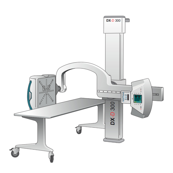
DX-D 300 | Introduction | 13 Configuration DX-D 300 is a DR X-ray system (Direct Radiography X-ray system) that can be combined with components from a CR X-ray system. The complete DX-D 300 consists of the following components: • Vertical column with U-arm •... - Page 14 14 | DX-D 300 | Introduction Mobile table DR Detector U-arm Vertical column X-Ray tube Figure 1: DX-D 300 configuration with integrated DR Detector 0172G EN 20230627 1651...
-
Page 15: Operation Controls
DX-D 300 | Introduction | 15 Operation Controls NX application and software console X-Ray generator control box DR Detector handle control buttons Collimator control panel U-arm control panel Figure 2: DX-D 300 operation controls Topics: • MUSICA Acquisition Workstation (NX) •... -
Page 16: Musica Acquisition Workstation (Nx)
16 | DX-D 300 | Introduction MUSICA Acquisition Workstation (NX) The MUSICA Acquisition workstation is used to define patient information, select exposures and process images. Figure 3: MUSICA Acquisition workstation software The operation of the workstation application is described in the MUSICA Acquisition Workstation User Manual, document 4420. -
Page 17: Software Console On The Nx Workstation
DX-D 300 | Introduction | 17 Software Console on the NX Workstation The Software Console is used to control X-Ray generator settings and X-Ray system position. The software console has two screens: Figure 4: X-Ray generator controls Figure 5: X-Ray system automatic posi-... -
Page 18: Dr Detector Switch
18 | DX-D 300 | Introduction DR Detector Switch The DR Detector Switch is available in the title bar of the MUSICA Acquisition Workstation. The DR Detector Switch shows which DR detector is active and shows its status. The DR Detector Switch can be used to activate another DR detector. - Page 19 DX-D 300 | Introduction | 19 Meaning DR detector DR detector is DR detector is DR detector is is ready for initializing for off or discon- inactive (no exposure exposure nected or in thumbnail se- error lected) 0172G EN 20230627 1651...
-
Page 20: X-Ray Generator Control In The Operator Room
20 | DX-D 300 | Introduction X-Ray generator control in the operator room The X-Ray generator control box contains buttons to switch on and off the X- Ray generator and a handswitch to make exposures. Figure 8: the X-Ray generator control box... -
Page 21: U-Arm Control Panel
DX-D 300 | Introduction | 21 U-arm control panel On the U-arm.the control panel with touch screen console and control buttons to control X-Ray generator settings and U-arm position. DX-D MOVE Figure 9: U-arm control panel 0172G EN 20230627 1651... -
Page 22: Control Panel Of The Collimator
22 | DX-D 300 | Introduction Control panel of the collimator The control panel of the automatic collimator: Figure 10: the control panel of the automatic collimator The display shows the dimensions of the collimated area and of the source image distance (SID) in centimeters or in inches. -
Page 23: Dr Detector Handle Control Buttons
DX-D 300 | Introduction | 23 DR Detector handle control buttons The DR Detector handle control buttons to control the U-arm position Figure 11: DR Detector handle control buttons 0172G EN 20230627 1651... -
Page 24: U-Arm Remote Control
24 | DX-D 300 | Introduction U-arm remote control The remote control to control U-arm position MOVE DETECTOR ROTATION TUBE ROTATION Figure 12: U-arm remote control 0172G EN 20230627 1651... -
Page 25: Portable Dr Detector
DX-D 300 | Introduction | 25 Portable DR detector When performing an exposure, keep in mind the following detector orientation aids: Table 1: Orientation aids Tube side icon, indicating the side that faces the X- ray tube Patient orientation marker, filled rectangle printed at... -
Page 26: Emergency Stop Button
26 | DX-D 300 | Introduction Emergency stop button Figure 13: Emergency stop button If a system malfunction causes an emergency situation involving the patient, operating personnel or any system component, activate the emergency stop. All motor driven system movements will be stopped. -
Page 27: Emergency Shutdown Power Switch
DX-D 300 | Introduction | 27 Emergency shutdown power switch Use the emergency shutdown power switch, if a dangerous situation cannot be eliminated by pressing the emergency stop button. WARNING: Use the emergency shutdown power switch in case of danger to patients, operators, third parties, or one of the units. -
Page 28: System Documentation
28 | DX-D 300 | Introduction System Documentation The user documentation consists of: • DX-D 300 User Documentation CD (digital media). • NX User Documentation CD (digital media). • User documentation for the supported DR Detectors • Digitizer User Documentation CD (digital media). -
Page 29: The Dx-D 300 User Documentation
DX-D 300 | Introduction | 29 The DX-D 300 User Documentation • DX-D 300 User Manual (this document), document 0172. • DX-D 300 U-arm User Manual, document 0174. • DX-D Full Leg Full Spine User Manual, document 0179. • DX-D DR Detector Calibration Key User Manual, document 0134. -
Page 30: Options And Accessories
• DX-D Full Leg Full Spine Stand (for the DX-D Full Leg Full Spine application) • CR FLFS Cassette Holder (for the CR Full Leg Full Spine application) For options and accessories information, refer to the DX-D 300 U-arm User Manual, document 0174. Anti-scatter grids Anti-scatter grids are used to reduce scattered radiation and improve image quality. -
Page 31: Product Complaints
Contact address: Agfa Service Support - local support addresses and phone numbers are listed on www.agfa.com Agfa - Septestraat 27, 2640 Mortsel, Belgium Agfa - Fax +32 3 444 7094... -
Page 32: Compliance
32 | DX-D 300 | Introduction Compliance Topics: • General • Safety • Electromagnetic Compatibility • X-Ray Safety • Classification 0172G EN 20230627 1651... -
Page 33: General
DX-D 300 | Introduction | 33 General • The product has been designed in accordance with Regulation (EU) 2017/745 on medical devices (MDR) Safety • IEC 60601-1 Electromagnetic Compatibility • IEC 60601-1-2 X-Ray Safety • IEC 60601-1-3 • IEC 60601-2-54 •... -
Page 34: Classification
34 | DX-D 300 | Introduction Classification Type of protection against Class 1 Equipment electric shock Degree of protection Type B Applied Part against electric shock Degree of protection IPX0 as defined in IEC60529. Ordinary equip- against ingress of liquids ment (enclosed equipment without protection against ingress of liquids). -
Page 35: Connectivity
DX-D 300 | Introduction | 35 Connectivity The NX workstation is connected to the X-ray system to exchange X-ray exposure parameters. The NX workstation requires a 100 Mbit ethernet network to exchange information with a number of other devices. The NX workstation communicates with other devices in the hospital network using one of the following protocols: •... -
Page 36: Labels
36 | DX-D 300 | Introduction Labels Lable Meaning This mark shows compliance of the equipment with Regulation 2017/745 (for European Un- ion). Type B applied part Serial number Manufacturer Date of manufacture Dangerous voltage Ionizing radiation The INMETRO label is positioned close to the type label. - Page 37 DX-D 300 | Introduction | 37 Mark Meaning The 21 CFR Subchapter J label is positioned close to the type label. 0172G EN 20230627 1651...
-
Page 38: Messages
The user must read these messages carefully. They will provide information on what to do from then on. This will be either performing an action to resolve the problem or to contact the Agfa service organization. Details on the contents of messages can be found in the service documentation which is available to Agfa service personnel. -
Page 39: Installation
1.5 m (IEC/EN 60601-1) or 1.83 m (ANSI/AAMI ES60601-1) around the patient (according to the local valid regulation). The other components of the DX-D 300 are suitable for use within the patient environment. Labeling the DR detectors... -
Page 40: Cleaning And Disinfecting
40 | DX-D 300 | Introduction Cleaning and Disinfecting All appropriate policies and procedures should be followed to avoid contamination of the staff, patients and equipment. All existing universal precautions should be extended to avoid potential contaminations and to avoid patients coming into (close) contact with the device. The user is responsible for selecting a disinfection procedure. -
Page 41: Cleaning
DX-D 300 | Introduction | 41 Cleaning To clean the exterior of the equipment: 1. Stop the system. CAUTION: Wet cleaning of the equipment while it is connected to the electric circuit includes the risk of electric shock and of short circuit. -
Page 42: Disinfecting
If you plan to use other disinfectants, approval of Agfa is needed before use, as most disinfectants can damage the device. UV disinfection is also not allowed. Perform the procedure following the instructions for use, the disposal instructions and the safety instructions of the selected disinfectants and tools and of the hospital. -
Page 43: Approved Disinfectants
DX-D 300 | Introduction | 43 Approved disinfectants Refer to the Agfa website for specifications on the disinfectants that have been found compatible with the cover material of the device and can be used on the outer surface of the device. -
Page 44: Patient Data Security
(ISP), set in compliance with point 17(4) and 18(8) of Annex I of the EU Medical Device Regulation 2017/745, must be implemented and used in connection with the use of the Agfa medical device by the Customer (User). These are minimum requirements and designed to protect against unauthorised access that could hamper the device from functioning as intended. - Page 45 DX-D 300 | Introduction | 45 • Medical devices shall be on an isolated network segment that restricts communication of the medical devices to the systems that are required for the device to function. • Internal firewalls shall be put in place to improve upon network segmentation and to further restrict communications of medical devices to the systems (internal and external) that they need to interact with.
-
Page 46: Maintenance
46 | DX-D 300 | Introduction Maintenance Maintenance procedures are described in the DX-D 300 Owner’s Manual. 0172G EN 20230627 1651... -
Page 47: Environmental Protection
DX-D 300 | Introduction | 47 Environmental protection Figure 15: WEEE symbol Figure 16: Battery symbol WEEE end user notice The directive on Waste Electrical and Electronic Equipment (WEEE) aims to prevent the generation of electric and electronic waste and to promote the reuse, recycling and other forms of recovery. - Page 48 48 | DX-D 300 | Introduction For battery replacements please contact your local sales organization. 0172G EN 20230627 1651...
-
Page 49: Safety Directions
Safety is only guaranteed when changes, additions, maintenance or repairs are carried out by an Agfa certified field service engineer. A non certified engineer performing a modification or service intervention on a medical device, acts on his own responsibility and makes the warranty void. - Page 50 Strictly observe all warnings, cautions, notes and safety markings within this document and on the product. CAUTION: All Agfa medical products must be used by trained and qualified personnel. CAUTION: Avoid unnecessary dose by checking before exposure if the DR...
- Page 51 DX-D 300 | Introduction | 51 specified range, do not operate the system or use air conditioning. Frost due to low temperatures can damage internal circuits. Warranty will be void if it is obvious that operating conditions are not met.
-
Page 52: Operation
52 | DX-D 300 | Operation Operation Topics: • Starting DX-D 300 • Performing an exposure using the DR Detector • Performing a Full Leg Full Spine examination • Performing an exposure using a CR cassette • Stopping the System... -
Page 53: Starting Dx-D 300
DX-D 300 | Operation | 53 Starting DX-D 300 Note: Allow the DR Detector to warm up before the DX-D 300 is used for clinical purposes. The warming-up time starts as soon as the DR Detector has been powered on and the NX workstation is running. -
Page 54: Performing An Exposure Using The Dr Detector
54 | DX-D 300 | Operation Performing an exposure using the DR Detector Topics: • Step 1: retrieve the patient info • Step 2: Select the exposure • Step 3: Prepare the exposure • Step 4: Check the exposure settings •... -
Page 55: Step 1: Retrieve The Patient Info
DX-D 300 | Operation | 55 Step 1: retrieve the patient info At the MUSICA Acquisition Workstation: 1. When a new patient comes in, define the patient info for the exam. 2. Start the exam. If the workstation is connected to a second monitor that is positioned outside the operator room, make sure that the patient data is not exposed to unauthorized persons. -
Page 56: Step 2: Select The Exposure
56 | DX-D 300 | Operation Step 2: Select the exposure In the operator room at the NX workstation: Select the thumbnail for the exposure in the Image Overview pane of the Examination window. U-arm with integrated DR Detector Portable DR Detector in the DR bucky Free exposure using a portable DR Detector The selected DR Detector is activated. -
Page 57: Step 3: Prepare The Exposure
DX-D 300 | Operation | 57 Step 3: Prepare the exposure 1. In the examination room, position the U-arm: Press and hold the MOVE button on the U-arm control panel or remote control. The U-arm moves to the default position for the selected exposure. -
Page 58: Step 4: Check The Exposure Settings
58 | DX-D 300 | Operation Step 4: Check the exposure settings Related Links DR Detector Switch on page 18 On the NX application: 1. Check if the DR Detector Switch displays the name of the DR Detector that's being used 2. -
Page 59: Step 5: Execute The Exposure
DX-D 300 | Operation | 59 Step 5: execute the exposure In the operator room: Press the exposure button to execute the exposure. Make sure the generator is ready for exposure before you press the exposure button. WARNING: The radiation indicator on the control console lights up during exposure release. -
Page 60: Step 6: Perform A Quality Control
60 | DX-D 300 | Operation Step 6: perform a quality control At the MUSICA Acquisition Workstation: 1. Select the image on which quality control is to be performed. 2. Prepare the image for diagnosis by using e.g. L/R markers or annotations. -
Page 61: Performing A Full Leg Full Spine Examination
DX-D 300 | Operation | 61 Performing a Full Leg Full Spine examination Refer to the DR Full Leg Full Spine User Manual (document 0179). The availability of DR Full Leg Full Spine depends on the configuration of the system. -
Page 62: Performing An Exposure Using A Cr Cassette
62 | DX-D 300 | Operation Performing an exposure using a CR cassette Note: Using an ID Tablet to identify cassettes before the exposure will break the communication of X-ray parameters between the NX workstation and the X-ray generator console. It is advised to identify cassettes after the exposure, as described in this workflow. -
Page 63: Step 1: Retrieve The Patient Info
DX-D 300 | Operation | 63 Step 1: retrieve the patient info At the MUSICA Acquisition Workstation: 1. When a new patient comes in, define the patient info for the exam. 2. Start the exam. If the workstation is connected to a second monitor that is positioned outside the operator room, make sure that the patient data is not exposed to unauthorized persons. -
Page 64: Step 2: Select The Exposure
64 | DX-D 300 | Operation Step 2: select the exposure In the operator room at the NX workstation: 1. Select the thumbnail for the exposure in the Image Overview pane of the Examination window. Cassette in the DR bucky... -
Page 65: Step 3: Prepare The Exposure
DX-D 300 | Operation | 65 Step 3: Prepare the exposure 1. In the examination room, position the U-arm: Press and hold the MOVE button on the U-arm control panel or remote control. The U-arm moves to the default position for the selected exposure. -
Page 66: Step 4: Check The Exposure Settings
66 | DX-D 300 | Operation Step 4: Check the exposure settings In the operator room at the software console, or in the examination room at the touch screen console: 1. Check if the exposure settings displayed on the console are suitable for the exposure. -
Page 67: Step 5: Execute The Exposure
DX-D 300 | Operation | 67 Step 5: Execute the exposure In the operator room: Press the exposure button to execute the exposure. WARNING: The radiation indicator on the control console lights up during exposure release. In the operator room at the NX workstation: •... -
Page 68: Step 6: Repeat Steps 2 To 5 For The Next Subexposures
68 | DX-D 300 | Operation Step 6: repeat steps 2 to 5 for the next subexposures 0172G EN 20230627 1651... -
Page 69: Step 7: Digitize The Image
DX-D 300 | Operation | 69 Step 7: digitize the image In the examination room: Take the exposed cassette. In the operator room: 1. Insert the cassette in the digitizer. 2. Click ID in the examination window of NX. Note: You can also use an ID Tablet to identify the cassette and digitize it using any digitizer. -
Page 70: Step 8: Perform A Quality Control
70 | DX-D 300 | Operation Step 8: perform a quality control In the operator room at the NX workstation: 1. Select the image on which quality control is to be performed. 2. Prepare the image for diagnosis by using e.g. L/R markers or annotations. -
Page 71: Stopping The System
DX-D 300 | Operation | 71 Stopping the System To stop the system: 1. Stop the MUSICA Acquisition workstation. The MUSICA Acquisition workstation can be stopped in two ways, either by logging out of Windows or without logging out of Windows. -
Page 72: Operating The Dx-D Software Console
72 | DX-D 300 | Operating the DX-D Software Console Operating the DX-D Software Console Topics: • Device Status Frame • DAP Display Frame • Error Status Frame • Generator Controls Window • X-Ray Modality Controls Window 0172G EN 20230627 1651... -
Page 73: Device Status Frame
DX-D 300 | Operating the DX-D Software Console | 73 Device Status Frame Figure 17: Device status frame Topics: • Modality Position • Filter Status • Anti-scatter grid status • Position Status • Ready For Exposure • Preparation • X-Ray On •... -
Page 74: Modality Position
74 | DX-D 300 | Operating the DX-D Software Console Modality Position The modality position is automatically selected, based on the selected exposure. To modify the position on the modality where the exposure will be made, click the drop-down arrow and select the modality position from the list. - Page 75 DX-D 300 | Operating the DX-D Software Console | 75 Table 3: DR detector status Icon Status description Grey: the image is planned and the DR detector is in sleep mode. Green: the DR detector is ready to acquire the exposure on the se- lected acquisition system.
-
Page 76: Filter Status
76 | DX-D 300 | Operating the DX-D Software Console Filter Status On systems with automatic filtering, the filter is automatically set, based on the selected exposure. The filter setting can be modified on the software console or on the collimator. -
Page 77: Anti-Scatter Grid Status
DX-D 300 | Operating the DX-D Software Console | 77 Anti-scatter grid status • The grid status is automatically detected. Table 6: Grid status - automatically detected Empty: no grid is required. Green: the correct grid is inserted. The grid type is specified. -
Page 78: Position Status
78 | DX-D 300 | Operating the DX-D Software Console Position Status The position status is available on systems with automatic positioning. Table 8: Position status Icon Description On target. The position of the X-ray system matches the target posi- tion. -
Page 79: Ready For Exposure
DX-D 300 | Operating the DX-D Software Console | 79 Ready For Exposure An icon indicates whether the X-ray system is ready for taking the exposure. Table 9: Exposure ready Icon Description Exposure ready. Indicates that the selected technique is properly set and there are no interlock failures or system faults. -
Page 80: Preparation
80 | DX-D 300 | Operating the DX-D Software Console Preparation Figure 18: Prep Press the handswitch halfway (“Prep” position) to prepare the X-ray tube for exposure. The indicator will light up when the X-ray tube is prepared and there are no interlock failures or system faults. -
Page 81: X-Ray On
DX-D 300 | Operating the DX-D Software Console | 81 X-Ray On Figure 19: X-ray on After pressing the handswitch completely, the X-ray exposure is made. The indicator on the console will light up. 0172G EN 20230627 1651... -
Page 82: Heat Units
82 | DX-D 300 | Operating the DX-D Software Console Heat Units The status of the heat units is displayed below the X-ray icon. During exposures, the heat units are calculated and totalled. The heat units display shows the percentage of the thermal capacity of the X-ray tube that is used. -
Page 83: Dap Display Frame
DX-D 300 | Operating the DX-D Software Console | 83 DAP Display Frame The Dose Display shows the radiation value of the last exposure. The radiation measure is read as DAP value (Dose Area Product) in cGy*cm2 (for example: 12.22 cGycm2). -
Page 84: Error Status Frame
84 | DX-D 300 | Operating the DX-D Software Console Error Status Frame 1. Button to confirm errors The Error Status frame displays warnings, error numbers and error descriptions. If the error has been resolved, the “CONT.” button becomes active. Click the active button to reset the error condition. -
Page 85: Generator Controls Window
DX-D 300 | Operating the DX-D Software Console | 85 Generator Controls Window Radiographic parameters Focal spot indicator AEC buttons X-ray tube load Figure 22: Generator controls Topics: • Radiographic Parameters • Focal Spot Indicator • X-Ray Tube Load •... -
Page 86: Radiographic Parameters
86 | DX-D 300 | Operating the DX-D Software Console Radiographic Parameters You can set up following radiographic parameters: Figure 23: Radiographic parameters To increase the radiographic parameters step by step, use the UP and DOWN arrows. The values increase or decrease step by step each time the corresponding button is touched. - Page 87 DX-D 300 | Operating the DX-D Software Console | 87 terminated even if the target dose is not reached. Not available in Free Exposure mode using DR or Free Exposure mode using CR. When using AEC, the exposure is terminated by the max ms or max mAs settings, even if the target dose is not reached.
-
Page 88: Focal Spot Indicator
88 | DX-D 300 | Operating the DX-D Software Console Focal Spot Indicator A focal spot indicator shows the selected focal spot of the X-ray tube: “Small” or “Large”. Figure 24: Focal spot indicator You can change the focal spot by touching this indicator. It keeps kVp and constant mAs, whenever it is possible. -
Page 89: X-Ray Tube Load
DX-D 300 | Operating the DX-D Software Console | 89 X-Ray Tube Load As a way to increase the tube life cycle, the power percentage of the tube is reduced to a 80% by default. If a specific technique requires 100% of the X-ray tube power, touch the 100% button. -
Page 90: Automatic Exposure Control (Aec)
90 | DX-D 300 | Operating the DX-D Software Console Automatic Exposure Control (AEC) Automatic Exposure Control (AEC) produces consistent density with excellent contrast regardless of the radiographic technique selected. The AEC module comprises the controls for the selection of the exposure detector fields (ion chamber), sensitivity and density compensation. - Page 91 DX-D 300 | Operating the DX-D Software Console | 91 Figure 27: Sensitivity Density These buttons are used to adjust the AEC cut-off dose (and patient entrance dose accordingly). Figure 28: Density Density can be increased and decreased in a range of -4 to +4. Each step gives a difference of 25% in dose (25% is the default setting).
- Page 92 92 | DX-D 300 | Operating the DX-D Software Console Figure 29: Patient size AEC Backup Time If the exposure is aborted by the AEC back-up timer, the “CONT.” button blinks and the message “Not Enough Dose” is shown on the software console.
-
Page 93: Radiographic Working Modes
DX-D 300 | Operating the DX-D Software Console | 93 Radiographic Working Modes You can select following radiographic working modes according to the parameters to be controlled and the degree of automation: • One Point Mode (1P), by selecting kVp with AEC operations. - Page 94 94 | DX-D 300 | Operating the DX-D Software Console Two Point Mode (2P) The value of kVp, mAs, max ms, the setting of focal spot and X-ray tube load can be adjusted. The value of mA and ms are adjusted automatically to keep the mAs value constant, within the boundaries of generator or X-ray tube limitations.
-
Page 95: X-Ray Modality Controls Window
DX-D 300 | Operating the DX-D Software Console | 95 X-Ray Modality Controls Window Topics: • Positioning Parameters • Collimator Parameters 0172G EN 20230627 1651... -
Page 96: Positioning Parameters
96 | DX-D 300 | Operating the DX-D Software Console Positioning Parameters On systems with automatic positioning, the target position is automatically set, based on the selected exposure. To modify the target position, you can: • scroll through the preconfigured set of target positions by clicking the automatic position selection buttons. - Page 97 DX-D 300 | Operating the DX-D Software Console | 97 Figure 34: “On target” position status To make final adjustments to the position, use the position controls on the X- ray system. The type of X-ray system defines which automatic positions and positioning parameters are available.
-
Page 98: Collimator Parameters
98 | DX-D 300 | Operating the DX-D Software Console Collimator Parameters On systems with an automatic collimator, the collimation is automatically set, based on the selected exposure. To modify the automatic collimation, increase or decrease the collimator parameters step by step, using the UP and DOWN arrows. The values increase or decrease step by step each time the corresponding button is touched. -
Page 99: Problem Solving
DX-D 300 | Problem solving | 99 Problem solving Topics: • DR Detector is Exceeding the Maximum Working Temperature • DR detector must be recalibrated • DR Detector Problem • Radiographic Parameter Limits • Self-diagnosis Indicators 0172G EN 20230627 1651... -
Page 100: Dr Detector Is Exceeding The Maximum Working Temperature
100 | DX-D 300 | Problem solving DR Detector is Exceeding the Maximum Working Temperature Details A message is displayed on NX indicating that the DR De- tector is exceeding the maximum working temperature. Cause Due to ambient temperature conditions and the number of acquired images, the DR Detector’s internal tempera-... -
Page 101: Radiographic Parameter Limits
DX-D 300 | Problem solving | 101 Radiographic Parameter Limits If the value of a radiographic parameter cannot be increased or decreased, one of these limits may be applied: • Radiographic Parameters Limit. A maximum or minimum radiographic parameter limit is reached. An information message is displayed. - Page 102 102 | DX-D 300 | Problem solving Information message Description Max mAs Maximum mAs = 500 mAs (regulatory limit for AEC) Min ms Minimum exposure time (generator limit) Max ms Maximum exposure time (generator limit) Min ms & Min mA...
-
Page 103: Self-Diagnosis Indicators
DX-D 300 | Problem solving | 103 Self-diagnosis Indicators Self-diagnosis indicators identify a malfunction in the system alerting the operator that an error is inhibiting exposure. During normal operation of the system, these indicators are directly shown on the lower area of the console or as an error code close to the “CONT.”... - Page 104 104 | DX-D 300 | Problem solving Indicator Description TECHNIQUE ERROR Caution: If “TECHNIQUE ERROR” is displayed during exposure it means the exposure has been interrupted by the “Security Timer” because of a system failure. You should call field service.
-
Page 105: Technical Data
DX-D 300 | Technical Data | 105 Technical Data Topics: • DX-D 300 technical data • Portable DR detector technical data (mounted fixed in the bucky) • Fixed DR detector technical data • Fixed DR detector technical data • U-Arm technical data •... -
Page 106: Dx-D 300 Technical Data
106 | DX-D 300 | Technical Data DX-D 300 technical data The technical data are provided in this chapter or in the user manual of the component. Table 13: Electrical connection Rated power supply 230 / 240 V∿ Single Phase 50/60 Hz Minimum input power required 2.5 kVA... -
Page 107: Portable Dr Detector Technical Data (Mounted Fixed In The Bucky)
DX-D 300 | Technical Data | 107 Portable DR detector technical data (mounted fixed in the bucky) Manufacturer Manufacturer DR detector Vieworks Co., Ltd. (Gwanyang-dong), 41-3, Burim-ro 170beon-gil, Dongan-gu, Anyang-si, Gyeonggi-do, Korea Distributor DR detector Agfa NV Septestraat 27, B-2640 Mortsel - Belgium... - Page 108 108 | DX-D 300 | Technical Data Image acquisition time (mini- mum cycle time) Conversion screen Pixel size 140 µm Active pixel matrix 3072 x 3072 Effective pixel matrix 3048 x 3048 Detector type amorphous silicium Active area size 430 mm x 430 mm Effective area size 426.7.0 mm x 426.7 mm...
-
Page 109: Fixed Dr Detector Technical Data
DX-D 300 | Technical Data | 109 Fixed DR detector technical data Manufacturer Manufacturer DR detector Varex Imaging Corporation, 1678 So. Pioneer Rd, Salt Lake City, UT 84104, USA Supported models 4343R (part number 7965) CsI conversion screen 4343R (part number 7964) - Page 110 110 | DX-D 300 | Technical Data Reliability Estimated product life (if regularly serviced 100 000 RAD and maintained according to Agfa instruc- tions) 0172G EN 20230627 1651...
-
Page 111: Fixed Dr Detector Technical Data
DX-D 300 | Technical Data | 111 Fixed DR detector technical data Manufacturer Manufacturer DR detector THALES AVS FRANCE SAS 460 Rue du Pommarin – BP122 38430 MOIRANS France Supported models Pixium RAD 4343 C-E CsI conversion screen Pixium RAD 4343 G-E... -
Page 112: Fixed Dr Detector Environmental Conditions
112 | DX-D 300 | Technical Data Fixed DR detector environmental conditions Pixium RAD 4343 C-E Environmental conditions (during normal operation) Temperature (ambient) between 15° and 35° Celsius Refer to environmental conditions of the X-ray sys- Humidity Atmospheric pressure Maximum altitude... -
Page 113: U-Arm Technical Data
DX-D 300 | Technical Data | 113 U-Arm technical data Manufacturer Manufacturer U-Arm Sedecal S.A. Polígono Ind. Rio de Janeiro 9-13 28110 Algete - Madrid Spain Refer to the DX-D 300 U-arm User Manual (document 0174) for technical data of the U-arm. 0172G EN 20230627 1651... -
Page 114: Portable Dr Detector Technical Data
114 | DX-D 300 | Technical Data Portable DR detector technical data Refer to the DR Detector User Manual. 0172G EN 20230627 1651... -
Page 115: Dose Area Product Meter (Iba Dap) Technical Data
DX-D 300 | Technical Data | 115 Dose Area Product Meter (IBA DAP) Technical Data Manufacturer IBA Dosimetry GmbH Bahnhofstrasse 5 DE-90592 Schwarzenbruck Supported Type 120-131 HS/RS485 Dose area product range (0.1...99999999.99) cGy x cm DAP resolution 0.01 cGy x cm Active area 14.0 cm x 14.0 cm... -
Page 116: Remarks For Hf-Emission And Immunity
116 | DX-D 300 | Remarks for HF-emission and immunity Remarks for HF-emission and immunity This equipment generates, uses, and can radiate radio frequency energy. CAUTION: The equipment may cause radio frequency interference to other medical or non medical devices and to radio communications. - Page 117 The DX-D 300 system is intended for use in the electromagnetic environment specified below. The customer or the user of this DX-D 300 system should assure that it is used in such an environment. Table 15: Guidance and manufacturer's declaration on electromagnetic...
- Page 118 118 | DX-D 300 | Remarks for HF-emission and immunity Table 16: Guidance and manufacturer's declaration on electromagnetic immunity Immunity IEC 60601-1-2 Compliance Electromagnetic en- Test Test Level Level vironment - guid- ance Electrostatic ± 8 kV contact ± 8 kV contact...
- Page 119 DX-D 300 | Remarks for HF-emission and immunity | 119 Magnetic field 30 A/m 30 A/m Magnetic field at the at the supply network frequency frequency should correspond to (50/60 Hz) the typical values as they are in a commer-...
-
Page 120: Immunity To Rf Wireless Communication Equipment
120 | DX-D 300 | Remarks for HF-emission and immunity (80% AM at (80% AM 1 kHz) at 1 kHz) Note: The ISM (industrial, scientific and medical) bands between 0.15 MHz and 80 MHz are 6.765 MHz to 6.795 MHz; 13.553 MHz to 13.567 MHz;...
Need help?
Do you have a question about the DX-D 300 and is the answer not in the manual?
Questions and answers