IDEC MICROSmart FC6A Series User Manual
Windldr
Hide thumbs
Also See for MICROSmart FC6A Series:
- User manual (578 pages) ,
- Ladder programming manual (604 pages)
Table of Contents
Advertisement
Advertisement
Table of Contents

Related Manuals for IDEC MICROSmart FC6A Series


Summary of Contents for IDEC MICROSmart FC6A Series
- Page 1 B-1722(16) FC6A SERIES User’s Manual...
-
Page 2: Safety Precautions
Read the "FC6A Series MICROSmart User’s Manual" to ensure correct operation before starting installation, wiring, operation, maintenance, and inspection of the FC6A Series MICROSmart. All FC6A Series MICROSmart modules are manufactured under IDEC’s rigorous quality control system, but users must add a backup or failsafe ... - Page 3 Caution notices are used where inattention might cause personal injury or damage to equipment. Caution The FC6A Series MICROSmart is designed for installation in a cabinet. Do not install the FC6A Series MICROSmart outside a cabinet. Install the FC6A Series MICROSmart in environments described in the "FC6A Series MICROSmart User’s Manual". If the FC6A Series ...
-
Page 4: About This Manual
Read this manual to ensure the correct understanding of the entire functions of the FC6A Series MICROSmart. IDEC Corporation makes the latest product manual PDFs available on our website at no additional cost. Please download the latest product manual PDFs from our website. - Page 5 NK (Nippon Kaiji Kyokai) * This product has not been certified for use on the bridge or deck. For details on applicable standards and EU directives, please contact the dealer where purchased or check the IDEC website. FC6A S MICROS ’...
- Page 6 IMPORTANT INFORMATION Under no circumstances shall IDEC Corporation be held liable or responsible for indirect or consequential damages resulting from the use of or the application of IDEC PLC components, individually or in combination with other equipment. All persons using these components must be willing to accept responsibility for choosing the correct component to suit their application and for choosing an application appropriate for the component, individually or in combination with other equipment.
-
Page 7: About The Warranty Of The Products
Products will be repaired free of charge. If such failure or defects should occur, please offer them to the distributor, dealer or IDEC CORPORATION with the materials in which the date of purchase is specified. -
Page 8: Related Manuals
ELATED ANUALS The following manuals related to the FC6A Series MICROSmart are available. Refer to them in conjunction with this manual. Type No. Manual Name Description Describes product specifications, installation and wiring instructions, instructions for FC6A Series MICROSmart FC9Y-B1722 basic programming operations and special functions, device and instruction lists, and User’s Manual (this manual) troubleshooting procedures for the FC6A Series MICROSmart. - Page 9 AMES AND BBREVIATIONS SED IN THIS ANUAL Model Names Name Used in This Manual Type Number, Part Code, or Official Name FC6A Series MICROSmart FC6A Series MICROSmart FC6A-C16R1AE, FC6A-C16R1CE, FC6A-C16K1CE, FC6A-C16P1CE, FC6A-C16R1DE, FC6A-C16K1DE, FC6A-C16P1DE, FC6A-C24R1AE, All-in-One CPU module FC6A-C24R1CE, FC6A-C24K1CE, FC6A-C24P1CE, FC6A-C40R1AE, FC6A-C40R1CE, FC6A-C40K1CE, FC6A-C40P1CE, FC6A-C40R1DE, FC6A-C40K1DE, FC6A-C40P1DE FC6A-C40R1AEJ, FC6A-C40R1CEJ, FC6A-C40K1CEJ, FC6A-C40P1CEJ,...
- Page 10 Name Used in this Manual WindLDR Operating Procedure Function area settings Configuration tab > Function Area Settings group Monitors Select Online > Monitor > Start Monitor. PLC status Select Online > PLC > Status. Communication settings Select Online > Communication > Set Up. On the Configuration tab, in Function Area Settings, click Communication Ports, and in the Modbus master request table displayed Function Area Settings dialog box, for Communication Mode under Communication...
-
Page 11: Table Of Contents
ABLE OF ONTENTS Safety Precautions..........................Preface-1 About This Manual..........................Preface-3 About the Warranty of the Products....................Preface-6 Related Manuals..........................Preface-7 Names and Abbreviations Used in this Manual ..................Preface-8 General Information HAPTER About the FC6A Series MICROSmart ......................1-1 Features ..............................1-8 Special Functions............................ -
Page 12: Hapter
ABLE OF ONTENTS Ladder Program Operation..........................4-17 Start/Stop Operation ..........................4-18 Functions and Settings HAPTER Function List............................... 5-1 Function Area Settings ..........................5-3 Stop Input and Reset Input ......................... 5-5 Run/Stop Selection at Keep Data Error ......................5-9 Run/Stop Selection at Power Up........................5-10 Function Switch Configuration........................5-11 Memory Backup ............................5-13 High-Speed Counter ...........................5-15... - Page 13 ABLE OF ONTENTS Source and Destination Devices........................8-6 Using Timer or Counter as Source Device...................... 8-6 Using Timer or Counter as Destination Device ....................8-6 Data Types for Advanced Instructions ......................8-7 Discontinuity of Device Areas ........................8-11 NOP (No Operation) ..........................8-11 Device Addressing for Instruction Execution ....................
- Page 14 ABLE OF ONTENTS Preface-13 FC6A S MICROS ’ FC9Y-B1722 ERIES MART ANUAL...
-
Page 15: About The Fc6A Series Microsmart
1: G ENERAL NFORMATION Introduction This chapter describes FC6A Series MICROSmart functions and system configuration examples. About the FC6A Series MICROSmart The FC6A Series MICROSmart is a small, All-in-One CPU module or Plus CPU module programmable controller with excellent expandability and a variety of communication functions. The CPU modules are equipped with 16-, 24-, 32-, or 40-I/Os and support either 100 to 240V AC, 24V DC, or 12V DC power supplies. - Page 16 1: G ENERAL NFORMATION HMI module FC6A - PH 1 Interface specification 1: Communication connector Module type PH: HMI module Cartridge base module FC6A - HPH1 Module type HPH1: Cartridge base module Digital I/O modules FC6A - M 0 8 B R 1 Terminal specification 1: Removable terminal block (Screw) 3: MIL connector...
- Page 17 1: G ENERAL NFORMATION Analog I/O module FC6A - J 4 C N 1 Isolation Y: Isolated between channels None: No isolation Terminal specification 1: Removable terminal block (Screw) 4: Removable terminal block (Push-in) Input type None: Voltage/current input N: Voltage/current/resistance thermometer input U: Thermistor/thermocouple input H: Thermocouple input Maximum resolution...
- Page 18 1: G ENERAL NFORMATION Expansion interface module FC6A - EXM 2 Terminal specification 1: Removable terminal block (Screw) 4: Removable terminal block (Push-in) Module configuration 1M: Remote master 1S: Remote slave 2: Expander Module type EXM: Expansion interface module Digital I/O cartridge FC6A - P N 4 I/O points 4: 4 I/O points...
- Page 19 1: G ENERAL NFORMATION Connector FC6A - P M T C K 1 1 P N 0 2 Quantity per pack 02: 2 items Sale configuration PN: 1 pack Number of pins 03: 3 pins 05: 5 pins 08: 8 pins 09: 9 pins 10: 10 pins 11: 11 pins...
- Page 20 1: G ENERAL NFORMATION Battery holder FC6A - B H N 0 2 Quantity per pack 02: 2 items Sale configuration PN : 1 pack Type 2 1: Standard product Product classification BH: Battery holder FC6A S MICROS ’ FC9Y-B1722 ERIES MART ANUAL...
- Page 21 1: G ENERAL NFORMATION CPU Module Type Numbers and Functions List Type numbers and functions Number of Analog Type Inputs and Ethernet Ethernet Serial Power Supply Cartridge Memory Input/ Number Outputs Port Port 1 Port 2 Port Port 1 Slots Card Slot Volume 16 (404)
-
Page 22: Features
1: G ENERAL NFORMATION Features This section describes the features of the FC6A Series MICROSmart. High-speed Instruction Processing The FC6A Series MICROSmart is capable of high-speed arithmetic processing of basic instructions (LOD) in 0.042 μs and advanced instructions (MOV) in 0.120 μs. This improves real time performance during program execution. Abundant Program Capacity The FC6A Series MICROSmart has large program capacity. -
Page 23: Special Functions
1: G ENERAL NFORMATION Special Functions This section describes the functions of the FC6A Series MICROSmart. I/O Related Functions Catch Input The catch input function is used to receive shot pulses (minimum pulse width: 5 μs) that is shorter than the user program scan time. - Page 24 1: G ENERAL NFORMATION High-speed I/O Functions High-speed Counter This function counts high-speed pulse inputs that cannot be measured in normal user program processing. Use this function for applications such as positioning control with a rotary encoder or motor control. The FC6A Series MICROSmart can use single-phase high-speed counters and two-phase high-speed counters.
- Page 25 1: G ENERAL NFORMATION Convenient Functions Calendar/Clock The FC6A Series MICROSmart features a real-time clock on-board. Using the calendar and clock function, the FC6A Series MICROSmart can operate according to the current date and time. These functions can be used to control a time schedule for lighting or air conditioning equipments.
-
Page 26: Communication Functions
1: G ENERAL NFORMATION Communication Functions The FC6A Series MICROSmart can perform RS232C and RS485 communication using serial port 1. The communication ports can be expanded by using communication cartridges to allow for multiple instances of RS-232C, RS-485, and Bluetooth communication. - Page 27 1: G ENERAL NFORMATION Allocations of the Communication Port Numbers All-in-One CPU module, CAN J1939 All-in-One CPU module, and Plus CPU module support serial communication with the target device. Serial communication is possible with built-in interface or expanded interface of each CPU module. Interfaces supporting the serial communication are as follows: All-in-One CPU module : Serial port 1, cartridge slots 1 and 2, communication module ports...
-
Page 28: Maintenance Communication
1: G ENERAL NFORMATION Maintenance Communication The maintenance communication of the FC6A Series MICROSmart enables you to check the operating status and I/O status of the FC6A Series MICROSmart, monitor and change device values, and download and upload user programs with the PLC programming software WindLDR installed on a computer. -
Page 29: User Communication
1: G ENERAL NFORMATION User Communication The user communication of the FC6A Series MICROSmart enables you to control external devices such as computers, printers, and barcode readers. For details on user communication, see the "FC6A Series MICROSmart Communication Manual". Supported ports Communication Cartridge USB Port Serial Port 1... -
Page 30: Data Link Communication
1: G ENERAL NFORMATION Data Link Communication The FC6A Series MICROSmart supports data link communication, and it can share data between CPU modules using serial port 1 and cartridge slots. The FC6A Series MICROSmart can also share data with FC5A Series and FC4A Series CPU modules. Configure the settings in WindLDR to enable distributed control of a maximum of 31 CPU modules. -
Page 31: Ethernet Communication
When accessing the FC6A Series MICROSmart over the Internet, adequate security measures for the network to prevent unauthorized access are required. Be sure to consult your network administrator or Internet service provider. IDEC bears no responsibility for damages or problems caused due to security in Ethernet communication. -
Page 32: Operator Interface Connectivity
NFORMATION Operator Interface Connectivity The FC6A Series MICROSmart can perform maintenance communication with IDEC operator interfaces using Ethernet port 1, serial port 1, and communication cartridge. FC6A Series MICROSmart device values can be monitored and modified by the connected operator interface. An Ethernet cable or an O/I communication cable is used to connect the FC6A Series MICROSmart and the operator interface. -
Page 33: Bacnet Communication
1: G ENERAL NFORMATION BACnet Communication The Plus CPU module can be connected to a BACnet/IP network using Ethernet port 1 and communicate with other BACnet communication-compatible external devices. For details on BACnet communications, see the "FC6A Series MICROSmart Communication Manual". Supported ports Communication Cartridge and USB Port... -
Page 34: Ethernet/Ip Communication
1: G ENERAL NFORMATION EtherNet/IP Communication The Plus CPU module can be connected to an Ethernet network using Ethernet port 2 and communicate with other EtherNet/IP communication-compatible external devices. EtherNet/IP communication uses standard Ethernet technologies, which allows networks to be built that include various Ethernet-compatible devices. For details on EtherNet/IP communications, see the "FC6A Series MICROSmart Communication Manual". -
Page 35: Mqtt Communication
1: G ENERAL NFORMATION MQTT Communication The Plus CPU module can communicate with a broker as a client (publisher and subscriber) in MQTT communication using Ethernet port 1. For details on MQTT communications, see the "FC6A Series MICROSmart Communication Manual". Supported ports Communication Cartridge and... - Page 36 1: G ENERAL NFORMATION 1-22 FC6A S MICROS ’ FC9Y-B1722 ERIES MART ANUAL...
-
Page 37: Normal Operating Conditions
2: P RODUCT PECIFICATIONS This chapter describes the part names and specifications of the modules that make up the FC6A Series MICROSmart. Various types of modules are available for the FC6A Series MICROSmart. These include the CPU modules (All-in-One CPU module, CAN J1939 All-in-One CPU module, and Plus CPU module), digital I/O modules (digital input modules, digital output modules, and digital mixed I/O modules), analog I/O modules (analog input modules, analog output modules, and analog mixed I/O modules), PID modules, communication modules, expansion interface modules (expander and remote master/slave), HMI modules, cartridge... - Page 38 2: P RODUCT PECIFICATIONS Status of Support for Expanded Ambient Operating Temperatures (-25 to -10°C and 55 to 65°C) Applicability of Expanded Ambient Operating Temperature Name Type No. Status Version All-in-One CPU module FC6A-C*****E Applicable HV200 or later CAN J1939 All-in-One CPU module FC6A-C40***EJ Applicable HV200 or later...
- Page 39 2: P RODUCT PECIFICATIONS Applicability of Expanded Ambient Operating Temperature Name Type No. Status Version FC6A-PC1 — Communication cartridge FC6A-PC3 Not applicable — FC6A-PC4 — FC6B-C16R1A/FC6B-C16R4A FC6B-C16R1C/FC6B-C16R4C FC6B-C16K1C/FC6B-C16K4C FC6B-C16P1C/FC6B-C16P4C FC6B-C24R1A/FC6B-C24R4A FC6B-C24R1C/FC6B-C24R4C FC6B-C24K1C/FC6B-C24K4C FC6B-C24P1C/FC6B-C24P4C FC6B series FC6B-C40R1A/FC6B-C40R4A Applicable HV200 or later FC6B-C40R1C/FC6B-C40R4C FC6B-C40K1C/FC6B-C40K4C FC6B-C40P1C/FC6B-C40P4C...
-
Page 40: Cpu Module
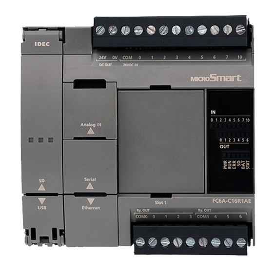
2: P RODUCT PECIFICATIONS CPU Module All-in-One CPU module/CAN J1939 All-in-One CPU module The All-in-One CPU module is equipped with analog input and serial ports (RS-232C/RS-485). CAN J1939 All-in-One CPU module is equipped with a CAN port. Part Names and Functions ■... - Page 41 2: P RODUCT PECIFICATIONS (1) Sensor power terminals (AC power type only) These terminals supply DC power (24V DC, 250 mA) for a sensor (can also be used as a power supply for inputs). The DC power type does not use these terminals. (2) Cartridge Slot 1 This slot is used to connect a digital I/O cartridge, analog I/O cartridge, or communication cartridge.
- Page 42 2: P RODUCT PECIFICATIONS (14) Status LED [STAT] This LED can be turned on or off in the user program. (15) Output Terminals These terminals connect output devices such as electromagnetic switches and solenoid valves. The CPU module is available in the relay output type (240V AC: 2 A, 30V DC: 2 A), the transistor sink output type (0.5 A), and the transistor protection source output type (0.5 A).
- Page 43 2: P RODUCT PECIFICATIONS (31) Serial Port 1 Cover A removable cover that protects Serial Port 1. When using the serial port, remove the Serial Port 1 cover. (32) Ethernet Port 1 Cover A removable cover that protects Ethernet Port 1. When using the Ethernet port, remove the Ethernet Port 1 cover. (33) Power Supply Terminals Cover An openable cover that protects the power supply terminals.
- Page 44 2: P RODUCT PECIFICATIONS (2) Cartridge Slot 1 (5) Battery Holder (3) Cartridge Slot 2 (1) Sensor Power Terminals (Not used with DC power (4) Input Terminals supply types.) (24) Function Switch (23) Communication Connector (6) Expansion Connector Left Side Right Side (7) Input LEDs [IN] (16) CAN Port...
- Page 45 2: P RODUCT PECIFICATIONS (4) Input Terminals These terminals connect input devices such as push buttons and limit switches. DC inputs are both sinks and sources. (5) Battery Holder This holder is for installing the backup battery. (6) Expansion Connector This connector is used to connect expansion modules.
- Page 46 2: P RODUCT PECIFICATIONS (18) LINK LED This LED is on when a network-compatible device is connected to Ethernet Port 1. (19) ACT LED This LED flashes when sending or receiving data while the LINK LED is on. (20) Power Supply Terminals These terminals are used to supply power to the CPU module.
- Page 47 2: P RODUCT PECIFICATIONS Power Supply Specifications ■ AC Power Type FC6A-C16R1AE, FC6A-C16R4AE, FC6A-C24R1AE,FC6A-C24R4AE, FC6A-C40R1AE, Type No. FC6A-C40R4AE, FC6A-C40R1AEJ, FC6A-C40R4AEJ Rated Operating Voltage 100 to 240V AC Voltage Fluctuation Range 85 to 264V AC Rated Power Frequency 50/60 Hz (47 to 63 Hz) Maximum Power Consumption Standalone When Maximum Load is Connected...
- Page 48 2: P RODUCT PECIFICATIONS ■ 24V DC Power Type FC6A-C16R1CE, FC6A-C16R4CE, FC6A-C16K1CE, FC6A-C16K4CE, FC6A-C16P1CE, FC6A-C16P4CE, FC6A-C24R1CE, FC6A-C24R4CE, FC6A-C24K1CE, FC6A-C24K4CE, Type No. FC6A-C24P1CE, FC6A-C24P4CE, FC6A-C40R1CE, FC6A-C40R4CE, FC6A-C40K1CE, FC6A-C40K4CE, FC6A-C40P1CE, FC6A-C40P4CE, FC6A-C40R1CEJ, FC6A-C40R4CEJ, FC6A-C40K1CEJ, FC6A-C40K4CEJ, FC6A-C40P1CEJ, FC6A-C40P4CEJ Rated Power Voltage 24V DC Voltage Fluctuation Range 20.4 to 28.8V DC (including ripple) Maximum Power Consumption...
- Page 49 2: P RODUCT PECIFICATIONS Ground D-type ground (Class 3 ground) Grounding Wire See "Recommended Ferrule List" on page 3-46 Power Supply Wire See "Recommended Ferrule List" on page 3-46 Reverse polarity: Normal operation Effect of Improper Power Supply Improper voltage or frequency: Permanent damage may be caused Connection Improper lead connection: Permanent damage may be caused FC6A-C16R1CE...
- Page 50 2: P RODUCT PECIFICATIONS ■ 12V DC Power Type FC6A-C16R1DE, FC6A-C16R4DE, FC6A-C16K1DE, FC6A-C16K4DE, FC6A-C16P1DE, FC6A-C16P4DE, FC6A-C40R1DE, FC6A-C40R4DE, FC6A-C40K1DE, FC6A-C40K4DE, Type No. FC6A-C40P1DE, FC6A-C40P4DE, FC6A-C40R1DEJ, FC6A-C40R4DEJ, FC6A-C40K1DEJ, FC6A-C40K4DEJ, FC6A-C40P1DEJ, FC6A-C40P4DEJ Rated Power Voltage 12V DC Voltage Fluctuation Range 10.2 to 18V DC (including ripple) Maximum Power Consumption Standalone When Maximum Load is Connected...
- Page 51 2: P RODUCT PECIFICATIONS FC6A-C16R1DE 350 g FC6A-C16R4DE 350 g FC6A-C16K1DE 340 g FC6A-C16K4DE 340 g FC6A-C16P1DE 340 g FC6A-C16P4DE 340 g FC6A-C40R1DE 560 g FC6A-C40R4DE 565 g FC6A-C40K1DE 530 g Weight (approx.) FC6A-C40K4DE 535 g FC6A-C40P1DE 530 g FC6A-C40P4DE 535 g FC6A-C40R1DEJ 560 g...
- Page 52 2: P RODUCT PECIFICATIONS Function Specifications ■ CPU Module Performance FC6A-C16R1AE FC6A-C40R1AE FC6A-C40R1AEJ FC6A-C16R4AE FC6A-C40R4AE FC6A-C40R4AEJ FC6A-C16R1CE FC6A-C40R1CE FC6A-C40R1CEJ FC6A-C16R4CE FC6A-C24R1AE FC6A-C40R4CE FC6A-C40R4CEJ FC6A-C16K1CE FC6A-C24R4AE FC6A-C40K1CE FC6A-C40K1CEJ FC6A-C16K4CE FC6A-C24R1CE FC6A-C40K4CE FC6A-C40K4CEJ FC6A-C16P1CE FC6A-C24R4CE FC6A-C40P1CE FC6A-C40P1CEJ Type No. FC6A-C16P4CE FC6A-C24K1CE FC6A-C40P4CE FC6A-C40P4CEJ FC6A-C16R1DE FC6A-C24K4CE...
- Page 53 2: P RODUCT PECIFICATIONS Backup Function Backup Data RAM (internal relays, shift registers, counters, data registers) , clock Lithium ion primary cell (A battery is included with the product. The model of battery to be included Backup Battery with the product cannot be specified.) Panasonic: BR2032/CR2032A/CR2032B, Murata: CR2032X/CR2032W Battery Life Guaranteed 1 year, replacement recommended every 4 years (+25°C)
- Page 54 2: P RODUCT PECIFICATIONS Pulse Output (Transistor Output Type Only) FC6A-C16K1CE FC6A-C40K1CE FC6A-C40K1CEJ FC6A-C16K4CE FC6A-C40K4CE FC6A-C40K4CEJ FC6A-C16P1CE FC6A-C24K1CE FC6A-C40P1CE FC6A-C40P1CEJ FC6A-C16P4CE FC6A-C24K4CE FC6A-C40P4CE FC6A-C40P4CEJ Part No. FC6A-C16K1DE FC6A-C24P1CE FC6A-C40K1DE FC6A-C40K1DEJ FC6A-C16K4DE FC6A-C24P4CE FC6A-C40K4DE FC6A-C40K4DEJ FC6A-C16P1DE FC6A-C40P1DE FC6A-C40P1DEJ FC6A-C16P4DE FC6A-C40P4DE FC6A-C40P4DEJ Points Q0,Q1: 100kHz Maximum output...
- Page 55 2: P RODUCT PECIFICATIONS Ethernet Port 1 Points (When the HMI module is connected, this can be expanded by 1 point with the Ethernet port that has the web server function.) Communication Type IEEE 802.3 compliant Communication Speed 10BASE-T, 100BASE-TX Number of Connections Communication Functions Maintenance communication, user communication, Modbus TCP server/client...
- Page 56 2: P RODUCT PECIFICATIONS ■ All-in-One CPU Module Only Analog Potentiometer Points Data Resolution 0 to 1,000 Analog Input Points Input Range 0 to 10 V Data Resolution 0 to 1,000 Input Impedance Approx. 100 kΩ Error ±1% of full scale (±5% of full scale when noise is applied) Input Delay Time 12 ms (including the software filter) Maximum Allowed Steady Load...
- Page 57 2: P RODUCT PECIFICATIONS DC Input Specifications ■ AC Power Type, 24V DC Power Type FC6A-C40R1AE FC6A-C40R4AE FC6A-C40R1CE FC6A-C40R4CE FC6A-C16R1AE FC6A-C24R1AE FC6A-C40K1CE FC6A-C16R4AE FC6A-C24R4AE FC6A-C40K4CE FC6A-C16R1CE FC6A-C24R1CE FC6A-C40P1CE FC6A-C16R4CE FC6A-C24R4CE FC6A-C40P4CE Type No. FC6A-C16K1CE FC6A-C24K1CE FC6A-C40R1AEJ FC6A-C16K4CE FC6A-C24K4CE FC6A-C40R4AEJ FC6A-C16P1CE FC6A-C24P1CE FC6A-C40R1CEJ FC6A-C16P4CE...
- Page 58 2: P RODUCT PECIFICATIONS Operating Ranges The operating range of Type 1 (IEC 61131-2) DC input modules is as follows. I0, I1, I6, I7 I2 to I5, I10 to I27 Input Voltage (V DC) Input Voltage (V DC) 28.8 V 28.8 V ON Area ON Area...
- Page 59 2: P RODUCT PECIFICATIONS ■ 12V DC Power Type FC6A-C16R1DE FC6A-C40R1DE FC6A-C40R1DEJ FC6A-C16R4DE FC6A-C40R4DE FC6A-C40R4DEJ FC6A-C16K1DE FC6A-C40K1DE FC6A-C40K1DEJ Type No. FC6A-C16K4DE FC6A-C40K4DE FC6A-C40K4DEJ FC6A-C16P1DE FC6A-C40P1DE FC6A-C40P1DEJ FC6A-C16P4DE FC6A-C40P4DE FC6A-C40P4DEJ Rated Input Voltage 12V DC shared sink/source Input Voltage Range 0.0 to 18.0V DC I0, I1, I6, I7 5 mA/point (at 12V DC) Rated Input Current...
- Page 60 2: P RODUCT PECIFICATIONS Operating Ranges The operating range of Type 1 (IEC 61131-2) DC input modules is as follows. I0, I1, I6, I7 I2 to I5, I10 to I27 Input Voltage (V DC) Input Voltage (V DC) 18 V 18 V ON Area ON Area...
- Page 61 2: P RODUCT PECIFICATIONS Relay Output Specifications ■ AC Power Type, 24V DC Power Type, 12V DC Power Type FC6A-C40R1AE FC6A-C40R4AE FC6A-C40R1CE FC6A-C16R1AE FC6A-C40R4CE FC6A-C16R4AE FC6A-C24R1AE FC6A-C40R1DE FC6A-C16R1CE FC6A-C24R4AE FC6A-C40R4DE Type No. FC6A-C16R4CE FC6A-C24R1CE FC6A-C40R1AEJ FC6A-C16R1DE FC6A-C24R4CE FC6A-C40R4AEJ FC6A-C16R4DE FC6A-C40R1CEJ FC6A-C40R4CEJ FC6A-C40R1DEJ FC6A-C40R4DEJ...
- Page 62 2: P RODUCT PECIFICATIONS Transistor Sink Output Specifications ■ 24V DC power type FC6A-C16K1CE FC6A-C24K1CE FC6A-C40K1CE FC6A-C40K1CEJ Type No. FC6A-C16K4CE FC6A-C24K4CE FC6A-C40K4CE FC6A-C40K4CEJ No. of Outputs Output Points COM0 per Common COM1 ― ― Line Rated Load Voltage 24V DC Operating Load Voltage Range 20.4 to 28.8V DC Terminal Arrangement...
- Page 63 2: P RODUCT PECIFICATIONS ■ 12V DC Power Type FC6A-C16K1DE FC6A-C40K1DE FC6A-C40K1DEJ Type No. FC6A-C16K4DE FC6A-C40K4DE FC6A-C40K4DEJ No. of Outputs Output Points COM0 per Common COM1 ― Line Rated Load Voltage 12V DC Operating Load Voltage Range 10.2 to 18.0V DC 10.2 to 16.0V DC Terminal Arrangement See "12V DC Power Type"...
- Page 64 2: P RODUCT PECIFICATIONS Transistor Protection Source Output Specifications ■ 24V DC power type FC6A-C16P1CE FC6A-C24P1CE FC6A-C40P1CE FC6A-C40P1CEJ Type No. FC6A-C16P4CE FC6A-C24P4CE FC6A-C40P4CE FC6A-C40P4CEJ No. of Outputs Output Points COM0 per Common COM1 ― ― Line Rated Load Voltage 24V DC Operating Load Voltage Range 20.4 to 28.8V DC Terminal Arrangement...
- Page 65 2: P RODUCT PECIFICATIONS ■ 12V DC Power Type FC6A-C16P1DE FC6A-C40P1DE FC6A-C40P1DEJ Type No. FC6A-C16P4DE FC6A-C40P4DE FC6A-C40P4DEJ No. of Outputs Output Points COM0 per Common COM1 ― Line Rated Load Voltage 12V DC Operating Load Voltage Range 10.2 to 18.0V DC 10.2 to 16.0V DC Terminal Arrangement See "12V DC Power Type"...
- Page 66 2: P RODUCT PECIFICATIONS Ambient Temperature, Input Voltage, Output Voltage, I/O Simultaneous ON Ratio When the FC6A Series MICROSmart is used in an ambient temperature of 45°C or higher, reduce the input voltage and I/O utilization (simultaneous ON ratio: a%) according to the following diagrams. However, the following diagrams show the temperature conditions when the FC6A Series MICROSmart is normally installed.
- Page 67 2: P RODUCT PECIFICATIONS ■ Transistor sink output type There are no usage restrictions for input and output I/O when the ambient temperature is 55°C or lower and no cartridges are connected. When a cartridge is connected or the ambient temperature is greater than 55°C, reduce the input voltage, output voltage, and I/O ...
- Page 68 2: P RODUCT PECIFICATIONS ■ Transistor protection source output type When the ambient temperature is 55°C or lower and no cartridges are connected, reduce the input voltage, output voltage, and I/O simultaneous ON ratio as shown in the following diagrams. 24V DC Power Type Input I/O Output I/O...
- Page 69 2: P RODUCT PECIFICATIONS When a cartridge is connected or the ambient temperature is greater than 55°C, reduce the input voltage, output voltage, and I/O simultaneous ON ratio as shown in the following diagrams. 24V DC Power Type Input I/O Output I/O Input Voltage Output Voltage...
- Page 70 2: P RODUCT PECIFICATIONS Terminal Arrangement and Wiring Examples ■ AC Power Type 16-I/O Type: Screw fastened type: FC6A-C16R1AE Push-in type: FC6A-C16R4AE Applicable connector Screw fastened type FC6A-PMTD03PN02 (1) Power supply terminals Push-in type (AC) FC6A-PMSDA03PN02 Screw fastened type FC6A-PMTA12PN02 (2) Sensor power terminals, input terminals Push-in type FC6A-PMSA12PN02...
- Page 71 2: P RODUCT PECIFICATIONS 24-I/O Type: Screw fastened type: FC6A-C24R1AE Push-in type: FC6A-C24R4AE Applicable connector Screw fastened type FC6A-PMTD03PN02 (1) Power supply terminals Push-in type (AC) FC6A-PMSDA03PN02 FC6A-PMTA08PN02 Screw fastened type FC6A-PMTA09PN02 (2) Sensor power terminals, input terminals FC6A-PMSA08PN02 Push-in type FC6A-PMSA09PN02 Screw fastened type FC6A-PMTA13PN02...
- Page 72 2: P RODUCT PECIFICATIONS 40-I/O Type: Screw fastened type: FC6A-C40R1AE, FC6A-C40R1AEJ Push-in type: FC6A-C40R4AE, FC6A-C40R4AEJ Applicable connector Screw fastened type FC6A-PMTD03PN02 (1) Power supply terminals Push-in type (AC) FC6A-PMSDA03PN02 Screw fastened type FC6A-PMTA09PN02 (2) Sensor power terminals, input terminals Push-in type FC6A-PMSA09PN02 Screw fastened type FC6A-PMTA10PN02...
- Page 73 2: P RODUCT PECIFICATIONS ■ 24V DC Power Type 16-I/O type: Screw fastened type: FC6A-C16R1CE, FC6A-C16K1CE, FC6A-C16P1CE Push-in type: FC6A-C16R4CE, FC6A-C16K4CE, FC6A-C16P4CE Applicable connector Screw fastened type FC6A-PMTD03PN02 (1) Power supply terminals Push-in type (24 VDC) FC6A-PMSDC03PN02 Screw fastened type FC6A-PMTA12PN02 (2) Sensor power terminals, input terminals Push-in type...
- Page 74 2: P RODUCT PECIFICATIONS (3) Output terminals Relay Output: FC6A-C16R1CE, FC6A-C16R4CE Relay Output Q0 Q1 Q2 Q3 Q4 Q5 Q6 COM0 COM1 Transistor Sink Output: FC6A-C16K1CE, FC6A-C16K4CE Transistor Sink Output (24 V) Q1 Q2 Q3 Q4 Q5 COM0(-) V0(+) Transistor Protection Source Output: FC6A-C16P1CE, FC6A-C16P4CE Transistor Protection Source Output (24 V) Q1 Q2 Q3 Q4 Q5 COM0(+) V0(-)
- Page 75 2: P RODUCT PECIFICATIONS 24-I/O Type: Screw fastened type: FC6A-C24R1CE, FC6A-C24K1CE, FC6A-C24P1CE Push-in type: FC6A-C24R4CE, FC6A-C24K4CE, FC6A-C24P4CE Applicable connector Screw fastened type FC6A-PMTD03PN02 (1) Power supply terminals Push-in type (24 VDC) FC6A-PMSDC03PN02 FC6A-PMTA08PN02 Screw fastened type FC6A-PMTA09PN02 (2) Sensor power terminals, input terminals FC6A-PMSA08PN02 Push-in type FC6A-PMSA09PN02...
- Page 76 2: P RODUCT PECIFICATIONS (3) Output terminals Relay Output: FC6A-C24R1CE, FC6A-C24R4CE Relay Output Q0 Q1 Q2 Q3 Q4 Q5 Q6 Q7 Q10 Q11 COM0 COM1 COM2 Transistor Sink Output: FC6A-C24K1CE, FC6A-C24K4CE Transistor Sink Output (24 V) Q1 Q2 Q3 Q4 Q5 Q6 Q7 COM0(-) COM0(-)
- Page 77 2: P RODUCT PECIFICATIONS 40-I/O Type: Screw fastened type: FC6A-C40R1CE, FC6A-C40K1CE, FC6A-C40P1CE, FC6A-C40R1CEJ, FC6A-C40K1CEJ, FC6A-C40P1CEJ Push-in type: FC6A-C40R4CE, FC6A-C40K4CE, FC6A-C40P4CE, FC6A-C40R4CEJ, FC6A-C40K4CEJ, FC6A-C40P4CEJ Applicable connector Screw fastened type FC6A-PMTD03PN02 (1) Power supply terminals Push-in type (24 VDC) FC6A-PMSDC03PN02 Screw fastened type FC6A-PMTA09PN02 (2) Sensor power terminals, input terminals Push-in type...
- Page 78 2: P RODUCT PECIFICATIONS (3) Output terminals Relay Output: FC6A-C40R1CE, FC6A-C40R4CE, FC6A-C40R1CEJ, FC6A-C40R4CEJ Relay Output Relay Output Q0 Q1 Q2 Q3 Q4 Q5 Q6 Q7 Q10 Q11 Q12 Q13 Q14 Q15 Q16 Q17 COM0 COM1 COM2 COM3 Transistor Sink Output: FC6A-C40K1CE, FC6A-C40K4CE, FC6A-C40K1CEJ, FC6A-C40K4CEJ Transistor Sink Output (24 V) Transistor Sink Output (24 V) Q1 Q2 Q3 Q4 Q5...
- Page 79 2: P RODUCT PECIFICATIONS ■ 12V DC Power Type 16-I/O type: Screw fastened type: FC6A-C16R1DE, FC6A-C16K1DE, FC6A-C16P1DE Push-in type: FC6A-C16R4DE, FC6A-C16K4DE, FC6A-C16P4DE Applicable connector Screw fastened type FC6A-PMTD03PN02 (1) Power supply terminals Push-in type (12 VDC) FC6A-PMSDD03PN02 Screw fastened type FC6A-PMTA12PN02 (2) Sensor power terminals, input terminals Push-in type...
- Page 80 2: P RODUCT PECIFICATIONS (3) Output terminals Relay Output: FC6A-C16R1DE, FC6A-C16R4DE Relay Output Q0 Q1 Q2 Q3 Q4 Q5 Q6 COM0 COM1 Transistor Sink Output: FC6A-C16K1DE, FC6A-C16K4DE Transistor Sink Output (12 V) Q1 Q2 Q3 Q4 Q5 COM0(-) V0(+) Transistor Protection Source Output: FC6A-C16P1DE, FC6A-C16P4DE Transistor Protection Source Output (12 V) Q1 Q2 Q3 Q4 Q5 COM0(+) V0(-)
- Page 81 2: P RODUCT PECIFICATIONS 40-I/O Type: Screw fastened type: FC6A-C40R1DE, FC6A-C40K1DE, FC6A-C40P1DE, FC6A-C40R1DEJ, FC6A-C40K1DEJ, FC6A-C40P1DEJ Push-in type: FC6A-C40R4DE, FC6A-C40K4DE, FC6A-C40P4DE, FC6A-C40R4DEJ, FC6A-C40K4DEJ, FC6A-C40P4DEJ Applicable connector Screw fastened type FC6A-PMTD03PN02 (1) Power supply terminals Push-in type (12 VDC) FC6A-PMSDD03PN02 Screw fastened type FC6A-PMTA09PN02 (2) Sensor power terminals, input terminals Push-in type...
- Page 82 2: P RODUCT PECIFICATIONS (3) Output terminals Relay Output: FC6A-C40R1DE, FC6A-C40R4DE, FC6A-C40R1DEJ, FC6A-C40R4DEJ Relay Output Relay Output Q0 Q1 Q2 Q3 Q4 Q5 Q6 Q7 Q10 Q11 Q12 Q13 Q14 Q15 Q16 Q17 COM0 COM1 COM2 COM3 Transistor Sink Output: FC6A-C40K1DE, FC6A-C40K4DE, FC6A-C40K1DEJ, FC6A-C40K4DEJ Transistor Sink Output (12 V) Transistor Sink Output (12 V) Q1 Q2 Q3 Q4 Q5...
- Page 83 2: P RODUCT PECIFICATIONS Other Inputs and Ports ■ All-in-One CPU module (1) Analog input Signal Wire Cable Color AN(+) AN(-) Black (2) Serial Port 1 Signal Wire Signal Wire (RS-232C) (RS-485) ― ― ― ― ― ― ― ― Shell Shield Shield...
- Page 84 2: P RODUCT PECIFICATIONS ■ CAN J1939 All-in-One CPU module (1) CAN port Signal Wire Description CAN external power supply (-) CAN_L CAN_L bus line (dominant low) CAN_SHLD CAN cable shield CAN_H CAN_H bus line (dominant high) CAN external power supply (+). (V+) (This port is not used with the FC6A Series MICROSmart.) *1 Internally connected to the SG via a resistor and capacitor connected in a series.
- Page 85 2: P RODUCT PECIFICATIONS Plus CPU module Part Names and Functions Example: (3) Power LED [PWR] FC6A-D16*1CEE (2) SD Memory Card Slot (1) Battery Holder (4) Run LED [RUN] (5) Error LED [ERR] (6) SD Memory Card Status LED [SD] (7) Battery Status LED [BAT] (8) Status LED [STAT] (9) Input LEDs [IN]...
- Page 86 2: P RODUCT PECIFICATIONS (1) Battery Holder This holder is for installing the backup battery. (2) SD Memory Card Slot This slot is used to insert the SD memory card. (3) Power LED [PWR] This LED turns on when the power is supplied to the CPU module. (4) Run LED [RUN] This LED turns on while the CPU module is running the user program.
- Page 87 2: P RODUCT PECIFICATIONS (13) Input Terminals These terminals connect input devices such as push buttons and limit switches. DC inputs are both sinks and sources. (14) USB Port A mini-B type USB 2.0 connector. A USB cable can be attached to the FC6A Series MICROSmart and connected to a PC to download and upload user programs using WindLDR.
- Page 88 2: P RODUCT PECIFICATIONS (31) Ethernet Port 2 Cover A removable cover that protects Ethernet Port 2. When using the Ethernet port, remove the Ethernet Port 2 cover. (32) Ethernet Port 1 Cover A removable cover that protects Ethernet Port 1. When using the Ethernet port, remove the Ethernet Port 1 cover. (33) Communication Connector Protection Sticker This sticker protects the communication connector.
- Page 89 2: P RODUCT PECIFICATIONS Power Supply Specifications ■ 24V DC Power Type FC6A-D16R1CEE, FC6A-D16R4CEE, FC6A-D16K1CEE, FC6A-D16K4CEE, FC6A-D16P1CEE, Type No. FC6A-D16P4CEE, FC6A-D32K3CEE, FC6A-D32K4CEE, FC6A-D32P3CEE, FC6A-D32P4CEE Rated Power Voltage 24V DC Voltage Fluctuation Range 20.4 to 28.8V DC (including ripple) Maximum Power Consumption Standalone When Maximum Load is Connected FC6A-D16R1CEE/...
- Page 90 2: P RODUCT PECIFICATIONS FC6A-D16R1CEE 290 g FC6A-D16R4CEE 280 g FC6A-D16K1CEE 275 g FC6A-D16K4CEE 265 g FC6A-D16P1CEE 275 g Weight (approx.) FC6A-D16P4CEE 265 g FC6A-D32K3CEE 255 g FC6A-D32K4CEE 255 g FC6A-D32P3CEE 255 g FC6A-D32P4CEE 255 g 2-54 FC6A S MICROS ’...
- Page 91 2: P RODUCT PECIFICATIONS Function Specifications ■ CPU Module Performance FC6A-D16R1CEE, FC6A-D16R4CEE FC6A-D32K3CEE, FC6A-D32K4CEE Type No. FC6A-D16K1CEE, FC6A-D16K4CEE FC6A-D32P3CEE, FC6A-D32P4CEE FC6A-D16P1CEE, FC6A-D16P4CEE 800,000 bytes Program Data Program (100,000 steps) Capacity Comment Data 384,000 bytes Basic Expansion I/O Expansion Expansion Interface Cartridges Input Basic...
- Page 92 2: P RODUCT PECIFICATIONS Clock Function Accuracy ±30 seconds/month at 25°C Self-diagnostic Functions Keep data Power failure User program (ROM) CRC check Clock error Timer/counter preset value change check Data link connection check User program syntax check Expansion bus initialization check ...
- Page 93 2: P RODUCT PECIFICATIONS Input Delay Time 12 ms (including the software filter) Maximum Allowed Steady Load 13 V Isolation Not isolated Cable Unshielded cable 1 m (included with the product) Run/Stop Methods Power on/off Special internal relay (M8000) operation ...
- Page 94 2: P RODUCT PECIFICATIONS DC Input Specifications ■ 24V DC Power Type FC6A-D16R1CEE, FC6A-D16R4CEE FC6A-D32K3CEE, FC6A-D32K4CEE Type No. FC6A-D16K1CEE, FC6A-D16K4CEE FC6A-D32P3CEE, FC6A-D32P4CEE FC6A-D16P1CEE, FC6A-D16P4CEE Rated Input Voltage 24V DC shared sink/source Input Voltage Range 20.4 to 28.8V DC I0, I1, I3, I4, I6, I7 5 mA/point (at 24V DC) Rated Input Current I2, I5, I10 to I17 7 mA/point (at 24V DC)
- Page 95 2: P RODUCT PECIFICATIONS Input Internal Circuit I0, I1, I3, I4, I6, I7 4.7 kΩ Input I2, I5, I10 to I17 3.3 KΩ Input FC6A S MICROS ’ FC9Y-B1722 2-59 ERIES MART ANUAL...
- Page 96 2: P RODUCT PECIFICATIONS Relay Output Specifications ■ 24V DC Power Type Type No. FC6A-D16R1CEE, FC6A-D16R4CEE No. of Outputs COM1 Output Points per Common Line COM2 Terminal Arrangement See "24V DC Power Type" on page 2-64. Output Type 1a contact 2 A maximum Maximum Load Current 1 Common...
- Page 97 2: P RODUCT PECIFICATIONS Transistor Sink Output Specifications ■ 24V DC Power Type Type No. FC6A-D16K1CEE, FC6A-D16K4CEE FC6A-D32K3CEE, FC6A-D32K4CEE Output Points Output Points per Common Line Rated Load Voltage 24V DC Operating Load Voltage Range 20.4 to 28.8V DC Terminal Arrangement See "24V DC Power Type"...
- Page 98 2: P RODUCT PECIFICATIONS Transistor Protection Source Output Specifications ■ 24V DC Power Type Type No. FC6A-D16P1CEE, FC6A-D16P4CEE FC6A-D32P3CEE, FC6A-D32P4CEE Output Points Output Points per Common Line Rated Load Voltage 24V DC Operating Load Voltage Range 20.4 to 28.8V DC Terminal Arrangement See "24V DC Power Type"...
- Page 99 2: P RODUCT PECIFICATIONS Ambient Temperature, Input Voltage, Output Voltage, I/O Simultaneous ON Ratio When the FC6A Series MICROSmart is used in an ambient temperature of 45°C or higher, reduce the input voltage and I/O utilization (simultaneous ON ratio: a%) according to the following diagrams. However, the following diagrams show the temperature conditions when the FC6A Series MICROSmart is normally installed.
- Page 100 2: P RODUCT PECIFICATIONS Terminal Arrangement and Wiring Examples ■ 24V DC Power Type Plus 16-I/O type: Screw fastened type: FC6A-C16R1CEE, FC6A-D16K1CEE, FC6A-D16P1CEE Push-in type: FC6A-D16R4CEE, FC6A-D16K4CEE, FC6A-D16P4CEE Applicable connector Screw fastened type FC6A-PMTD03PN02 (1) Power supply terminals Push-in type FC6A-PMSDC03PN02 Screw fastened type FC6A-PMTCN10PN02...
- Page 101 2: P RODUCT PECIFICATIONS (3) Output terminals Relay Output: FC6A-D16R1CEE, FC6A-D16R4CEE COM0 Relay Output COM1 Transistor Sink Output: FC6A-D16K1CEE, FC6A-D16K4CEE Transistor Sink Output (24 V) COM (-) 24V DC COM (-) Transistor Protection Source Output: FC6A-D16P1CEE, FC6A-D16P4CEE Transistor Protection Source Output (24 V) COM (+) 24V DC COM (+)
- Page 102 2: P RODUCT PECIFICATIONS Plus 32-I/O type: Screw fastened type: FC6A-D32K3CEE, FC6A-D32P3CEE Push-in type: FC6A-D32K4CEE, FC6A-D32P4CEE Applicable connector Screw fastened type FC6A-PMTD03PN02 (1) Power supply terminals Push-in type FC6A-PMSDC03PN02 (2) Input terminals FC4A-PMC20PN02 (3) Output terminals FC4A-PMC20PN02 Screw fastened type Push-in type (1) Power supply terminals 24V DC Power Input...
- Page 103 2: P RODUCT PECIFICATIONS (3) Output terminals The two COM(+) and COM(-) lines are each connected in the module. The two +V and -V lines are each connected in the module. For wiring precautions, see "Input/Output Wiring" on page 3-18. For the connector cable, see "Cables"...
- Page 104 2: P RODUCT PECIFICATIONS Other Inputs and Ports (1) Analog input Signal Wire Cable Color AN(+) AN(-) Black (2) Ethernet Port 1 Signal Wire TPO+ TPO- TPI+ ― ― TPI- ― ― Shell Shield *1 Shell is connected to FE on the power supply terminals. (3) Ethernet Port 2 Signal Wire TPO+...
-
Page 105: Digital I/O Modules
2: P RODUCT PECIFICATIONS Digital I/O Modules Digital I/O modules are available as three types of modules: digital input modules equipped with input terminals, digital output modules equipped with output terminals, and digital mixed I/O modules equipped with both input and output terminals. Digital Input Module Parts Description Example: FC6A-N08B1... - Page 106 2: P RODUCT PECIFICATIONS Function Specifications ■ DC Input Module Specifications FC6A-N08B1 FC6A-N16B1 Type No. FC6A-N16B3 FC6A-N32B3 FC6A-N08B4 FC6A-N16B4 Rated Input Voltage 12/24V DC shared sink/source Operating Load Voltage Range 0.0 to 28.8V DC Rated Input Current 3.5 mA/point (at 12V DC), 7 mA/point (at 24V DC) 2.5 mA/point (at 12V DC), 5 mA/point (at 24V DC) 8 (8 points in 1 32 (16 points in 1...
- Page 107 2: P RODUCT PECIFICATIONS Input Internal Circuit FC6A-N08B1, FC6A-N08B4, FC6A-N16B1, FC6A-N16B4 3.3 KΩ Input FC6A-N16B3, FC6A-N32B3 4.3 KΩ Input Ambient Temperature, Input Voltage, Output Voltage, I/O Simultaneous ON Ratio When the FC6A Series MICROSmart is used in an ambient temperature of 30°C or higher, reduce the input voltage and I/O utilization (simultaneous ON ratio: a%) according to the following diagrams.
- Page 108 2: P RODUCT PECIFICATIONS ■ AC Input Module Specifications Type No. FC6A-N08A11, FC6A-N08A14 Rated Input Voltage 100 to 120V AC Operating Load Voltage Range 0 to 132V AC Rated Power Frequency 50/60 Hz Rated Input Current 15 mA/1 point (at 120V AC, 50/60 Hz) Input Points 8 points in 2 common lines Terminal Arrangement...
- Page 109 2: P RODUCT PECIFICATIONS Input Internal Circuit FC6-N08A11, FC6A-N08A14 470 kΩ 220 Ω Input 150 nF 2.21 kΩ Ambient Temperature, Input Voltage, Output Voltage, I/O Simultaneous ON Ratio At conditions where the ambient temperature is 55°C and the input voltage is 132 V, the inputs can be 100% used. ...
- Page 110 2: P RODUCT PECIFICATIONS Terminal Arrangement and Wiring Examples ■ FC6A-N08B1, FC6A-N08B4 Screw fastened type: FC6A-N08B1 Push-in type: FC6A-N08B4 Applicable connector: FC6A-PMTB11PN02 Applicable connector: FC6A-PMSB11PN02 DC.IN DC.IN FC6A-N08B1 FC6A-N08B4 The 3 COM lines are connected in the module. For wiring precautions, see "Input/Output Wiring" on page 3-18. DC Sink Input Wiring Example Terminal No.
- Page 111 2: P RODUCT PECIFICATIONS ■ FC6A-N16B1, FC6A-N16B4 Screw fastened type: FC6A-N16B1 Push-in type: FC6A-N16B4 Applicable connector: FC6A-PMTC10PN02 Applicable connector: FC6A-PMSC10PN02 DC.IN DC.IN FC6A-N16B1 FC6A-N16B4 The 4 COM lines are connected in the module. For wiring precautions, see "Input/Output Wiring" on page 3-18. DC Sink Input Wiring Example Terminal No.
- Page 112 2: P RODUCT PECIFICATIONS DC Source Input Wiring Example Terminal No. 2-wire Sensor 2-wire Sensor 12/24V DC *1 24V DC for products with a version number lower than V400. For details on the version number of modules, see "Checking the Version Number" on page 2-1.
- Page 113 2: P RODUCT PECIFICATIONS ■ FC6A-N16B3 Connector type Applicable connector: FC4A-PMC20PNO2 The two COM lines are each connected in the module. For wiring precautions, see "Input/Output Wiring" on page 3-18. For the connector cable, see "Cables" on page A-14. DC Sink Input Wiring Example DC.IN Terminal No.
- Page 114 2: P RODUCT PECIFICATIONS ■ FC6A-N32B3 Connector type Applicable connector: FC4A-PMC20PNO2 The two COM0 and COM1 lines are each connected in the module. Each of the terminals for COM0 and COM1 are independent. DC.IN For wiring precautions, see "Input/Output Wiring" on page 3-18. For the connector cable, see "Cables"...
- Page 115 2: P RODUCT PECIFICATIONS ■ FC6A-N08A11, FC6A-N08A14 Screw fastened type: FC6A-N08A11 Push-in type: FC6A-N08A14 Applicable connector: FC6A-PMTB11PN02 Applicable connector: FC6A-PMSB11PN02 AC.IN Ry.OUT FC6A-N08A14 FC6A-R081 Each of the terminals for COM0 and COM1 are independent. For wiring precautions, see "Input/Output Wiring" on page 3-18. AC input wiring example Terminal No.
- Page 116 2: P RODUCT PECIFICATIONS Digital Output Module Parts Description Example: FC6A-R081 Example: FC6A-T32K3 (2) Output LEDs (2) Output LEDs (5) Expansion Connector (5) Expansion Connector (4) Cable Terminal (3) Terminal Name Labels (1) Type Label (3) Terminal Name Label (4) Cable Terminals (4) Cable Terminal (1) Type Label Indicates the digital output module type number and specifications.
- Page 117 2: P RODUCT PECIFICATIONS Model List ■ Relay Output Modules Cable Terminal Type Relay Output 8 Points Relay Output 16 Points Screw fastened type FC6A-R081 Terminal block type ― (5.08 mm pitch) Push-in type FC6A-R084 Screw fastened type FC6A-R161 Terminal block type ―...
- Page 118 2: P RODUCT PECIFICATIONS Function Specifications ■ Relay Output Module Specifications Type No. FC6A-R081, FC6A-R084 FC6A-R161, FC6A-R164 No. of Outputs 8 (4 points in 1 common line) 16 (8 points in 1 common line) Output Type 1a contact Terminal Arrangement See 2-88 See 2-89 2 A maximum...
- Page 119 2: P RODUCT PECIFICATIONS Ambient Temperature, Input Voltage, Output Voltage, I/O Simultaneous ON Ratio When the FC6A Series MICROSmart is used in an ambient temperature of 55°C or higher, reduce the output voltage and I/O utilization (simultaneous ON ratio: a%) according to the following diagrams. However, the following diagrams show the temperature conditions when the FC6A Series MICROSmart is normally installed.
- Page 120 2: P RODUCT PECIFICATIONS ■ Transistor Sink Output Module Specifications FC6A-T08K1 FC6A-T16K1 Type No. FC6A-T16K3 FC6A-T32K3 FC6A-T08K4 FC6A-T16K4 Output Signal Transistor sink output Rated Load Voltage 12/24V DC Operating Load Voltage Range 10.2 to 28.8V DC No. of Outputs (8 points in 1 (16 points in 1 (16 points in 1 common line) common line)
- Page 121 2: P RODUCT PECIFICATIONS Ambient Temperature, Input Voltage, Output Voltage, I/O Simultaneous ON Ratio When the FC6A Series MICROSmart is used in an ambient temperature of 55°C or higher, reduce the output voltage and I/O utilization (simultaneous ON ratio: a%) according to the following diagrams. However, the following diagrams show the temperature conditions when the FC6A Series MICROSmart is normally installed.
- Page 122 2: P RODUCT PECIFICATIONS ■ Transistor Protection Source Output Module Specifications FC6A-T08P1 FC6A-T16P1 Type No. FC6A-T16P3 FC6A-T32P3 FC6A-T08P4 FC6A-T16P4 Output Signal Transistor protection source output Rated Load Voltage 24V DC Operating Load Voltage Range 20.4 to 28.8V DC No. of Outputs (8 points in 1 (16 points in 1 (16 points in 1 common line)
- Page 123 2: P RODUCT PECIFICATIONS Ambient Temperature, Input Voltage, Output Voltage, I/O Simultaneous ON Ratio When the FC6A Series MICROSmart is used in an ambient temperature of 55°C or higher, reduce the output voltage and I/O utilization (simultaneous ON ratio: a%) according to the following diagrams. However, the following diagrams show the temperature conditions when the FC6A Series MICROSmart is normally installed.
- Page 124 2: P RODUCT PECIFICATIONS Terminal Arrangement and Wiring Examples ■ FC6A-R081, FC6A-R084 Screw fastened type: FC6A-R081 Push-in type: FC6A-R084 Applicable connector: FC6A-PMTB11PN02 Applicable connector: FC6A-PMSB11PN02 Ry.OUT Ry.OUT FC6A-R084 FC6A-R081 Each of the terminals for COM0 and COM1 are independent. For wiring precautions, see "Input/Output Wiring" on page 3-18. : Fuse : Load Terminal No.
- Page 125 2: P RODUCT PECIFICATIONS ■ FC6A-R161, FC6A-R164 Screw fastened type: FC6A-R161 Push-in type: FC6A-R164 Applicable connector: FC6A-PMTC10PN02 Applicable connector: FC6A-PMSC10PN02 Ry.OUT Ry.OUT FC6A-R161 FC6A-R164 The two COM0 and COM1 lines are each connected in the module. Each of the terminals for COM0 and COM1 are independent. For wiring precautions, see "Input/Output Wiring"...
- Page 126 2: P RODUCT PECIFICATIONS ■ FC6A-T08K1, FC6A-T08K4 Screw fastened type: FC6A-T08K1 Push-in type: FC6A-T08K4 Applicable connector: FC6A-PMTB11PN02 Applicable connector: FC6A-PMSB11PN02 Tr.OUT Tr.OUT FC6A-T08K1 FC6A-T08K4 For wiring precautions, see "Input/Output Wiring" on page 3-18. : Fuse : Load Terminal No. COM(-) COM(-) COM(-) COM(-) 12/24V DC...
- Page 127 2: P RODUCT PECIFICATIONS ■ FC6A-T08P1, FC6A-T08P4 Screw fastened type: FC6A-T08P1 Push-in type: FC6A-T08P4 Applicable connector: FC6A-PMTB11PN02 Applicable connector: FC6A-PMSB11PN02 Tr.OUT Tr.OUT FC6A-T08P4 FC6A-T08P1 For wiring precautions, see "Input/Output Wiring" on page 3-18. : Fuse : Load Terminal No. COM(+) COM(+) 24V DC COM(+) COM(+)
- Page 128 2: P RODUCT PECIFICATIONS ■ FC6A-T16K1, FC6A-T16K4 Screw fastened type: FC6A-T16K1 Push-in type: FC6A-T16K4 Applicable connector: FC6A-PMTC10PN02 Applicable connector: FC6A-PMSC10PN02 Tr.OUT Tr.OUT FC6A-T16K1 FC6A-T16K4 The two COM(-) lines are each connected in the module. The two +V lines are each connected in the module. For wiring precautions, see "Input/Output Wiring"...
- Page 129 2: P RODUCT PECIFICATIONS ■ FC6A-T16P1, FC6A-T16P4 Screw fastened type: FC6A-T16P1 Push-in type: FC6A-T16P4 Applicable connector: FC6A-PMTC10PN02 Applicable connector: FC6A-PMSC10PN02 Tr.OUT Tr.OUT FC6A-T16P1 FC6A-T16P4 The two COM(+) lines are each connected in the module. The two -V lines are each connected in the module. For wiring precautions, see "Input/Output Wiring"...
- Page 130 2: P RODUCT PECIFICATIONS ■ FC6A-T16K3, FC6A-T16P3 Terminal block types Applicable connector: FC4A-PMC20PN02 The two COM(+) and COM(-) lines are each connected in the module. The two +V and -V lines are each connected in the module. For wiring precautions, see "Input/Output Wiring" on page 3-18. For the connector cable, see "Cables"...
- Page 131 2: P RODUCT PECIFICATIONS ■ FC6A-T32K3 Terminal block type Applicable connector: FC4A-PMC20PN02 The two COM0(-) and COM1(-) lines are each connected in the module. Each of the terminals for COM0(-) and COM1(-) are independent. Tr.OUT The two +V0 and +V1 lines are each connected in the module. Each of the terminals for +V0 and +V1 are independent.
- Page 132 2: P RODUCT PECIFICATIONS ■ FC6A-T32P3 Terminal block type Applicable connector: FC4A-PMC20PN02 The two COM0(+) and COM1(+) lines are each connected in the module. Each of the terminals for COM0(+) and COM1(+) are independent. Tr.OUT The two -V0 and -V1 lines are each connected in the module. Each of the terminals for -V0 and -V1 are independent.
- Page 133 2: P RODUCT PECIFICATIONS Digital Mixed I/O Module Parts Description Example: FC6A-M08BR1 Example: FC6A-M24BR1 (2) Input LEDs (2) Input LEDs (5) Expansion Connector Output LEDs Output LEDs (5) Expansion Connector (4) Cable Terminal (3) Terminal Name Labels (1) Type Label (3) Terminal Name Label (4) Cable Terminals (4) Cable Terminal...
- Page 134 2: P RODUCT PECIFICATIONS Function Specifications ■ Power Supply Specifications Type No. FC6A-M08BR1, FC6A-M08BR4 FC6A-M24BR1, FC6A-M24BR4 Input Points 4 (4 points in 1 common line) 16 (16 points in 1 common line) Points No. of Outputs 4 (4 points in 1 common line) 8 (4 points in 1 common line) Terminal Arrangement See 2-101...
- Page 135 2: P RODUCT PECIFICATIONS Input Internal Circuit FC6A-M08BR1, FC6A-M08BR4, FC6A-M24BR1, FC6A-M24BR4 3.3 KΩ Input Ambient Temperature, Input Voltage, I/O Simultaneous ON Ratio When the FC6A Series MICROSmart is used in an ambient temperature of 45°C or higher, reduce the input voltage and I/O utilization (simultaneous ON ratio: a%) according to the following diagrams.
- Page 136 2: P RODUCT PECIFICATIONS ■ Output Specifications Type No. FC6A-M08BR1, FC6A-M08BR4 FC6A-M24BR1, FC6A-M24BR4 Output Points COM1 per Common COM2 ― Line Output Type 1a contact 2 A maximum Load Current 1 Common 7 A maximum Minimum Switching Load 1.0 mA/5.0V DC (reference value) Initial Contact Resistance 30 mΩ...
- Page 137 2: P RODUCT PECIFICATIONS Terminal Arrangement and Wiring Examples ■ FC6A-M08BR1, FC6A-M08BR4 Screw fastened type: FC6A-M08BR1 Push-in type: FC6A-M08BR4 Applicable connector: FC6A-PMTB11PN02 Applicable connector: FC6A-PMSB11PN02 DC.IN DC.IN Ry.OUT Ry.OUT FC6A-M08BR1 FC6A-M08BR4 Each of the terminals for COM0 and COM1 are independent. For wiring precautions, see "Input/Output Wiring"...
- Page 138 2: P RODUCT PECIFICATIONS DC Source Input Wiring Example Terminal No. 2-wire Sensor 12/24V DC COM0 COM0 COM1 COM1 *1 24V DC for products with a version number lower than V400. For details on the version number of modules, see "Checking the Version Number" on page 2-1.
- Page 139 2: P RODUCT PECIFICATIONS ■ FC6A-M24BR1, FC6A-M24BR4 Screw fastened type: FC6A-M24BR1 Push-in type: FC6A-M24BR4 Applicable connector: FC6A-PMTC17PN02 Applicable connector: FC6A-PMSC17PN02 FC6A-PMTC11PN02 FC6A-PMSC11PN02 DC.IN Ry.OUT DC.IN Ry.OUT FC6A-M24BR1 FC6A-M24BR4 The 3 COM lines are connected in the module. For wiring precautions, see "Input/Output Wiring" on page 3-18. DC Sink Input Wiring Example Terminal No.
- Page 140 2: P RODUCT PECIFICATIONS DC Source Input Wiring Example Terminal No. 2-wire Sensor 12/24V DC *1 24V DC for products with a version number lower than V400. For details on the version number of modules, see "Checking the Version Number" on page 2-1.
-
Page 141: Analog I/O Modules
2: P RODUCT PECIFICATIONS Analog I/O Modules Three type of analog I/O modules are available: analog input modules equipped with input terminals, analog output modules equipped with output terminals, and analog mixed I/O modules equipped with both input and output terminals. Parts Description Example: FC6A-J2C1 Example: FC6A-L06A1... - Page 142 2: P RODUCT PECIFICATIONS Model List Cable Terminal Cable Terminal Module Type I/O Points I/O Signal Type No. Type 1 Type 2 Screw fastened type FC6A-J2C1 Voltage input (0 to 10 V, -10 to +10 V) Terminal block type Current input (4 to 20 mA, 0 to 20 mA) (5.08 mm pitch) Push-in type FC6A-J2C4...
- Page 143 2: P RODUCT PECIFICATIONS Power Supply Specifications FC6A-J2C1 FC6A-J4A1 FC6A-J8A1 FC6A-J4CN1 FC6A-J4CH1Y Type No. FC6A-J2C4 FC6A-J4A4 FC6A-J8A4 FC6A-J4CN4 FC6A-J4CH4Y Power Supply 12/24V DC External Voltage Power Allowed 10.2 to 28.8V DC Fluctuation Range Terminal Arrangement 2-116 2-117 2-118 2-119 2-120 Connector Insertion/Removal 100 times minimum...
- Page 144 2: P RODUCT PECIFICATIONS Function Specifications ■ Analog Input Specifications Analog Input Module FC6A-J2C1 FC6A-J4A1 FC6A-J8A1 FC6A-J4CN1 FC6A-J4CH1Y FC6A-J8CU1 Type No. FC6A-J2C4 FC6A-J4A4 FC6A-J8A4 FC6A-J4CN4 FC6A-J4CH4Y FC6A-J8CU4 0 to 10 V Voltage ― -10 to 10 V 4 to 20 mA Current ―...
- Page 145 2: P RODUCT PECIFICATIONS FC6A-J2C1 FC6A-J4A1 FC6A-J8A1 FC6A-J4CN1 FC6A-J4CH1Y FC6A-J8CU1 Type No. FC6A-J2C4 FC6A-J4A4 FC6A-J8A4 FC6A-J4CN4 FC6A-J4CH4Y FC6A-J8CU4 65,536 4,096 65,536 Voltage 65,536 (16 bits) ― (16 bits) (12 bits) (16 bits) 65,536 4,096 65,536 Current 65,536 (16 bits) ― (16 bits) (12 bits) (16 bits)
- Page 146 2: P RODUCT PECIFICATIONS FC6A-J2C1 FC6A-J4A1 FC6A-J8A1 FC6A-J4CN1 FC6A-J4CH1Y FC6A-J8CU1 Type No. FC6A-J2C4 FC6A-J4A4 FC6A-J8A4 FC6A-J4CN4 FC6A-J4CH4Y FC6A-J8CU4 Maximum Permanent Allowed Overload 30V DC, 160mA or lowe (No Damage) Selection of Input Type and Input Using programming software Range Calibration or Verification to Maintain Not possible Rated Accuracy *1 The resistance (allowable conductor resistance) of the electrical leads to connect to the resistance thermometer is 10 Ω...
- Page 147 2: P RODUCT PECIFICATIONS Type No. FC6A-L06A1, FC6A-L06A4 FC6A-L03CN1, FC6A-L03CN4 Voltage 1 MΩ or higher Current 50 Ω or lower Thermocouple 1 MΩ or higher Input Impedance Resistance Thermometer 1 MΩ or higher Thermistor 1 MΩ or higher Resistor 1 MΩ or higher Sampling Time 1 ms or 10 ms 10 ms, 100 ms, or 104 ms...
- Page 148 2: P RODUCT PECIFICATIONS *2 The total input delay time increases in proportion to the number of channels used. Input channels that have been set to unused are not included in the number of enabled input channels. *3 The arbitrary setting is a function that uses the digital resolution data by scaling it to arbitrary data (that arbitrarily sets the lower limit value and the upper limit value).
- Page 149 2: P RODUCT PECIFICATIONS Input Internal Circuit FC6A-J2C1, FC6A-J2C4, FC6A-J4A1, FC6A-J4A4, FC6A-J8A1, FC6A-J8A4, FC6A-L06A1, FC6A-L06A4 2 MΩ 10 Ω Input Circuit 39 kΩ Switching Signal – FC6A-J4CN1, FC6A-J4CN4, FC6A-L03CN1, FC6A-L03CN4 Voltage Supply 10 Ω 2 MΩ 39 kΩ – Switching Signal B’...
- Page 150 2: P RODUCT PECIFICATIONS ■ Analog Output Specifications Voltage Current Output Type and Output Range 0 to 10 V 4 to 20 mA -10 to 10 V 0 to 20 mA Impedance 1 kΩ or higher 300 Ω or lower Load Load Type Resistive load...
- Page 151 2: P RODUCT PECIFICATIONS Output Internal Circuit Analog Signal Analog Output Element Switching Signal – Ambient Temperature and Analog Input/Output Restrictions Certain models of the analog module do not support expanded ambient operating temperatures (-25 to -10°C and 55 to 65°C). Do not use ...
- Page 152 2: P RODUCT PECIFICATIONS Terminal Arrangement and Wiring Examples When connecting the terminal, insert an IEC 60127-approved fuse suitable for the applied voltage and current draw at Caution the position shown in the following diagram. (Applicable when equipment containing the FC6A Series MICROSmart is destined for Europe) Do not connect a thermocouple to a part with hazardous voltage (60V DC or peak 42.4V DC or higher part).
- Page 153 2: P RODUCT PECIFICATIONS ■ FC6A-J4A1, FC6A-J4A4 Screw fastened type: FC6A-J4A1 Push-in type: FC6A-J4A4 Applicable connector: FC6A-PMTC10PN02 Applicable connector: FC6A-PMSC10PN02 ANALOG ANALOG FC6A-J4A1 FC6A-J4A4 For wiring precautions, see "Input/Output Wiring" on page 3-18. : Fuse Terminal No. 12/24V Analog Voltage/ current Output Device Analog Voltage/ current Output Device...
- Page 154 2: P RODUCT PECIFICATIONS ■ FC6A-J8A1, FC6A-J8A4 Screw fastened type: FC6A-J8A1 Push-in type: FC6A-J8A4 Applicable connector: FC6A-PMTC10PN02 Applicable connector: FC6A-PMSC10PN02 ANALOG ANALOG FC6A-J8A1 FC6A-J8A4 For wiring precautions, see "Input/Output Wiring" on page 3-18. : Fuse Terminal No. 12/24V Analog Voltage/ current Output Device Analog Voltage/ current Output Device...
- Page 155 2: P RODUCT PECIFICATIONS ■ FC6A-J4CN1, FC6A-J4CN4 Screw fastened type: FC6A-J4CN1 Push-in type: FC6A-J4CN4 Applicable connector: FC6A-PMTC10PN02 Applicable connector: FC6A-PMSC10PN02 ANALOG ANALOG FC6A-J4CN1 FC6A-J4CN4 For wiring precautions, see "Input/Output Wiring" on page 3-18. : Fuse Terminal No. 12/24V DC Analog Voltage/ current Output Device B’...
- Page 156 2: P RODUCT PECIFICATIONS ■ FC6A-J4CH1Y, FC6A-J4CH4Y Screw fastened type: FC6A-J4CH1Y Push-in type: FC6A-J4CH4Y Applicable connector: FC6A-PMTC10PN02 Applicable connector: FC6A-PMSC10PN02 ANALOG ANALOG FC6A-J4CH1Y FC6A-J4CH4Y For wiring precautions, see "Input/Output Wiring" on page 3-18. : Fuse Terminal No. 12/24V Thermocouple Thermocouple Thermocouple Thermocouple *1 24V DC for products with a version number lower than V400.
- Page 157 2: P RODUCT PECIFICATIONS ■ FC6A-J8CU1, FC6A-J8CU4 Screw fastened type: FC6A-J8CU1 Push-in type: FC6A-J8CU4 Applicable connector: FC6A-PMTC10PN02 Applicable connector: FC6A-PMSC10PN02 ANALOG ANALOG FC6A-J8CU1 FC6A-J8CU4 For wiring precautions, see "Input/Output Wiring" on page 3-18. : Fuse Terminal No. 12/24V NTC/PTC Thermistor NTC/PTC Thermistor NTC/PTC...
- Page 158 2: P RODUCT PECIFICATIONS ■ FC6A-K2A1, FC6A-K2A4 Screw fastened type: FC6A-K2A1 Push-in type: FC6A-K2A4 Applicable connector: FC6A-PMTB11PN02 Applicable connector: FC6A-PMSB11PN02 ANALOG ANALOG FC6A-K2A1 FC6A-K2A4 For wiring precautions, see "Input/Output Wiring" on page 3-18. : Fuse Terminal No. 12/24V Analog Voltage/ OUT0 current Input Device Analog Voltage/...
- Page 159 2: P RODUCT PECIFICATIONS ■ FC6A-K4A1, FC6A-K4A4 Screw fastened type: FC6A-K4A1 Push-in type: FC6A-K4A4 Applicable connector: FC6A-PMTB11PN02 Applicable connector: FC6A-PMSB11PN02 ANALOG ANALOG FC6A-K4A1 FC6A-K4A4 For wiring precautions, see "Input/Output Wiring" on page 3-18. : Fuse Terminal No. 24V DC Analog Voltage/ OUT0 current Input Device Analog Voltage/...
- Page 160 2: P RODUCT PECIFICATIONS ■ FC6A-L03CN1, FC6A-L03CN4 Screw fastened type: FC6A-L03CN1 Push-in type: FC6A-L03CN4 Applicable connector: FC6A-PMTB11PN02 Applicable connector: FC6A-PMSB11PN02 ANALOG ANALOG FC6A-L03CN4 FC6A-L03CN1 For wiring precautions, see "Input/Output Wiring" on page 3-18. : Fuse Terminal No. 12/24V DC OUT+ Analog Voltage/ current Input Device OUT-...
- Page 161 2: P RODUCT PECIFICATIONS ■ FC6A-L06A1, FC6A-L06A4 Screw fastened type: FC6A-L06A1 Push-in type: FC6A-L06A4 Applicable connector: FC6A-PMTC10PN02 Applicable connector: FC6A-PMSC10PN02 ANALOG ANALOG FC6A-L06A1 FC6A-L06A4 For wiring precautions, see "Input/Output Wiring" on page 3-18. : Fuse Terminal No. 24V DC Analog Voltage/ OUT0 current Input Device Analog Voltage/...
- Page 162 2: P RODUCT PECIFICATIONS Precautions when Supplying Power to the Analog I/O Module Separate analog I/O lines (resistance thermometers in particular) from power lines as much as possible to reduce the effect of noise. Terminal No. 24V DC Separate power lines and OUT+ I/O lines as much as possible.
-
Page 163: Pid Module
2: P RODUCT PECIFICATIONS PID Module The PID module performs control actions to eliminate the deviation between the set point (SP) and process variable (PV). The PID module, which is an expansion module, is required to connect to the CPU module for use. Depending on the difference of output specifications, the PID modules are categorized into two types. - Page 164 2: P RODUCT PECIFICATIONS (3) Control Output LEDs [OUT0, OUT1] On: Control output is on Off: Control output is off Flashing: For current output only, flashes at the duty cycle that corresponds to the output manipulated variable in a 100 ms cycle.
- Page 165 2: P RODUCT PECIFICATIONS Quantity of Applicable PID Modules The maximum number of PID modules that can be connected depends on the CPU module type. The maximum number of PID modules that can be connected to the CPU modules is as follows. Module Type Type No.
- Page 166 2: P RODUCT PECIFICATIONS Power Supply Specifications Type No. FC6A-F2M1, FC6A-F2M4 FC6A-F2MR1, FC6A-F2MR4 Power Supply Voltage 24V DC External Power Allowed Fluctuation 20.4 to 28.8V DC Range Terminal Arrangement See "Terminal Arrangement and Wiring Examples" on page 2-135 Insertion/Removal Connector 100 times minimum Durability Module...
- Page 167 2: P RODUCT PECIFICATIONS Type No. FC6A-F2M1, FC6A-F2M4, FC6A-F2MR1, FC6A-F2MR4 Within ±0.2% of full scale or ±2°C (4°F), whichever is larger Cold junction compensation accuracy: ±1.0°C or lower However, R, S input 0 to 200°C (0 to 400°F) is within ±6°C (12°F) Thermocouple B input 0 to 300°C (0 to 600°F) is outside the guaranteed range of Maximum Error at...
- Page 168 2: P RODUCT PECIFICATIONS Type No. FC6A-F2M1, FC6A-F2M4, FC6A-F2MR1, FC6A-F2MR4 Type Input Value per Step Pt100 1°C (°F) Pt100 (with decimal 0.1°C (°F) Input Value per Resistance point) Step Thermometer JPt100 1°C (°F) Data JPt100 (with decimal 0.1°C (°F) point) Data Type in Application Program Can be arbitrarily set for each CH in a range between -32,768 to 32,767 Monotonicity...
- Page 169 2: P RODUCT PECIFICATIONS ■ Output Specifications Type No. FC6A-F2M1, FC6A-F2M4 FC6A-F2MR1, FC6A-F2MR4 Output Transistor protection source output Digital Output Relay output Type and (12V DC output) Output Analog Output 4 to 20 mA ― Range Digital Output Max 40 mA (12V DC) ―...
- Page 170 2: P RODUCT PECIFICATIONS Output Delay Input to Relay Output Relay Status OFF Bounce: 6 ms maximum OFF Delay: 15 ms maximum ON Bounce: 6 ms maximum ON Delay: 10 ms maximum ■ Program Performance Item Specifications Time setting accuracy Within ±0.5% of the set time Progression time error after power interruption 6 minutes maximum...
- Page 171 2: P RODUCT PECIFICATIONS Terminal Arrangement and Wiring Examples When connecting the terminal, insert an IEC 60127-approved fuse suitable for the applied voltage and current draw at Caution the position shown in the following diagram. This is required when equipment containing the MICROSmart is destined for Europe. Do not connect a thermocouple to a part with hazardous voltage (60V DC or peak 42.4V DC or higher part).
- Page 172 2: P RODUCT PECIFICATIONS Precautions when Supplying Power to the PID Module When the PID module and the CPU module are set to the same power supply, the PID module will be initialized for a maximum of approximately 5 seconds after the power is turned on and the CPU module is set to run, so the parameters will not be stable. Always enable control after the module status flag changes to "0001H"...
-
Page 173: Communication Modules
2: P RODUCT PECIFICATIONS Communication Modules The communication modules include the serial communications module that communicate with peripheral devices using RS-232C or RS-485 communications. The communication modules are equipped with two serial ports, and RS-232C or RS-485 can be selected and used for each port. These modules support the maintenance communication function, user communication function, data link communication, and Modbus communication function. - Page 174 2: P RODUCT PECIFICATIONS Model List Module Type Points Type Cable Terminal Type Type No. Screw fastened type FC6A-SIF52 Communication module Serial communication interface (RS-232C/RS-485) Push-in type FC6A-SIF524 Note: A single port cannot be used as both RS-232C and RS-485 simultaneously. Function Specifications Type No.
- Page 175 2: P RODUCT PECIFICATIONS Maximum Number of Modules and Slots to Install The maximum number of communication modules that can be connected to the CPU module depends on the CPU module. The following table gives the maximum number of communication modules that can be connected to each CPU module and slots to install those modules.
- Page 176 2: P RODUCT PECIFICATIONS Location Expansion Interface Maximum CPU Module Remote Slave Module Module Type Type No. Number of Basic Expansion Basic Expansion Modules Expansion Interface Expansion Interface Side Side Side Side FC6A-D16R1CEE FC6A-D16R4CEE FC6A-D16K1CEE FC6A-D16K4CEE FC6A-D16P1CEE 7 modules + Plus CPU module ―...
- Page 177 2: P RODUCT PECIFICATIONS Terminal Arrangement and Wiring Examples ■ FC6A-SIF52, FC6A-SIF524 Screw fastened type: FC6A-SIF52 Push-in type: FC6A-SIF524 Applicable connector: FC6A-PMTC10PN02 Applicable connector: FC6A-PMSC10PN02 RS232C RS232C /RS485 /RS485 FC6A-SIF52 FC6A-SIF524 Terminal No. Signal Name RS1(RTS) Output Request to send ER1(DTR) Output Data terminal ready...
- Page 178 2: P RODUCT PECIFICATIONS Wiring Example When Using Both Ports Upper Side Port Terminal No. RS1(RTS) ER1(DTR) RS232C SD1(TxD) Interface RD1(RxD) Device DR1(DSR) Shield Terminating Resistance Lower Side Port Terminal No. RS2(RTS) ER2(DTR) SD2(TxD) RS485 RD2(RxD) Interface DR2(DSR) Device Shield Terminating Resistance RS485...
-
Page 179: Expansion Interface Modules
2: P RODUCT PECIFICATIONS Expansion Interface Modules The expansion interface modules are available as an expander that is added in between expansion modules to expand the number of connected modules and as remote modules (remote master and remote slave) that are daisy chained by Ethernet cables and allow expansion modules to be positioned away from the CPU module. - Page 180 2: P RODUCT PECIFICATIONS Function Specifications Type No. FC6A-EXM2, FC6A-EXM24 Rated Operating Voltage 24V DC (supplied from external power) Voltage Fluctuation Range 20.4 to 28.8V DC (including ripple) Internal Power CPU module side supply 20 mA (5V DC), 0 mA (24V DC) Current Draw External Power When maximum number of modules is connected...
- Page 181 2: P RODUCT PECIFICATIONS Power Supply Precautions When supplying the power to the CPU module and to the expansion interface module (expander) with different power supplies, turn the modules on and off in the order in the following table. An error may occur on the CPU module if the power on order or the power off order is mistaken. Power Supply Order Turn on the expansion interface module (expander) and the CPU module at the same time, or in expansion interface...
- Page 182 2: P RODUCT PECIFICATIONS Expansion Interface Modules (Remote Master/Slave) The Plus CPU module can be expanded with up to a maximum of 63 modules (I/O points: maximum 2,016 points) using expansion interface modules (remote master/slave). The expansion interface modules (remote master/slave) are the remote master which connects to the expansion connector of the Plus CPU module and the remote slave which connects to expansion modules that are positioned away from the CPU module.
- Page 183 2: P RODUCT PECIFICATIONS (1) For the remote master, connect expansion port [Exp. port M] to expansion port 1 [Exp. port S1] on the remote slave installed as node 1 using an Ethernet cable. (2) To install node 2, connect expansion port 2 [Exp. port S2] on the remote slave of node 1 to expansion port 1 [Exp. port S1] on the remote slave installed as node 2 using an Ethernet cable.
- Page 184 2: P RODUCT PECIFICATIONS (4) ACT LED [ACT] This LED flashes when the module is communicating with the expansion interface remote slave module connected using an Ethernet cable. (5) Expansion Connector 1 This connector is used to connect the Plus CPU module or an expansion module. (6) Expansion Connector 2 This connector is used to connect an expansion module.
- Page 185 2: P RODUCT PECIFICATIONS (5) ACT1 LED [ACT] When the LINK1 LED is on, this LED flashes when the module is communicating with the expansion interface remote master module or upstream expansion interface remote slave module. (6) LINK2 LED [LNK] This LED turns on when the downstream expansion interface remote slave module is connected to expansion port 2 [Exp.
- Page 186 2: P RODUCT PECIFICATIONS FC6A-EXM1M FC6A-EXM1S, FC6A-EXM1S4 Type No. (Expansion interface remote master module) (Expansion interface remote slave module) Ground D-type ground (Class 3 ground) Ground Wire See "Recommended Ferrule List" on page 3-46. Power Supply Wire — See "Recommended Ferrule List" on page 3-46. Insertion Power Supply /Removal...
- Page 187 2: P RODUCT PECIFICATIONS Power Supply Precautions When supplying the power to the CPU module, expansion interface remote slave modules, and expansion interface modules (expander) with separate power supplies, turn the modules on and off in the order given in the following table. An error will occur on the CPU module if the order to turn the power supply on and off is wrong.
-
Page 188: Hmi Module
2: P RODUCT PECIFICATIONS Maximum I/O Points When Using Expansion Interface Modules (Remote Master/Slave) The following table gives the number of digital I/O points and analog I/O points when expansion interface modules (remote master/slave) are connected to the Plus CPU module and the maximum number of expansion modules and cartridges are connected to the system. - Page 189 2: P RODUCT PECIFICATIONS Calculation Method of I/O Data Refresh Time When expansion modules are used with the CPU module, an approximate value for the I/O data refresh time can be calculated with the following equations. Use the I/O data refresh time obtained with the following equations as a rough estimate. ■...
- Page 190 2: P RODUCT PECIFICATIONS ■ When Using an Expansion Interface Module (Remote Master/Slave) (FC6A-EXM1M, FC6A-EXM1S, or FC6A-EXM1S4) 1. I/O data refresh time of node 0 I/O data refresh time = ( ) module(s) ) module(s) ) module(s) ) module(s) ) module(s) ×...
- Page 191 2: P RODUCT PECIFICATIONS Examples: Expansion Interface Remote Master Module Plus CPU Module (FC6A-EXM1M) Analog I/O Module Node 0 Communication Module Digital I/O Modules PID Module Node 1 Expansion Interface Remote Slave Module (FC6A-EXM1S, FC6A-EXM1S4) Digital I/O Modules Digital I/O PID Modules Module Node 2...
- Page 192 2: P RODUCT PECIFICATIONS 1. I/O data refresh time of node 0 I/O data refresh time = 6 × 0.34 ms + 2 × 0.04 ms + 1 × 0.17 ms + 1 × 0.34 ms + 1 × 1.09 ms + 11 ×...
- Page 193 2: P RODUCT PECIFICATIONS ■ When Using an Expansion Interface Module (FC6A-EXM2, FC6A-EXM24, FC6A-EXM1S, FC6A-EXM1S4, or FC6A-EXM1) 1. I/O data refresh time of node 0 I/O data refresh time = ( ) module(s) ) module(s) ) module(s) ) module(s) ) module(s) ×...
- Page 194 2: P RODUCT PECIFICATIONS Examples: Expansion Interface Expansion Interface Module Remote Master Module PID Modules (Expander) (FC6A-EXM2, FC6A-EXM24) Plus CPU Module (FC6A-EXM1M) Node 0 Digital I/O Modules Analog I/O Modules Communication Modules Digital I/O Modules Node 1 Expansion Interface Remote Slave Module (FC6A-EXM1S, FC6A-EXM1S4) Digital I/O Modules...
- Page 195 2: P RODUCT PECIFICATIONS 1. I/O data refresh time of node 0 I/O data refresh time = 8 × 0.68 ms + 5 × 0.08 ms + 4 × 0.29 ms + 2 × 0.58 ms + 2 × 1.09 ms + 18 × 0.08 ms + 28 × 0.29 ms + 4 ×...
- Page 196 2: P RODUCT PECIFICATIONS HMI Module The HMI module is connected to the CPU module's communication connector. You can run and stop the user program, monitor device values, and modify settings using the LCD and operation buttons on the HMI module. The HMI module also features the maintenance communication function, web server function, and send e-mail function using Ethernet communication.
- Page 197 2: P RODUCT PECIFICATIONS (8) Ground Terminal The functional ground terminal. (9) Dummy Cartridge A removable dummy cartridge that protects the cartridge slot. Remove the dummy cartridge when connecting a cartridge. (10) HMI-Ethernet Port This port allows Ethernet communication with connected devices that are equipped with an Ethernet interface. Function Specifications Type No.
- Page 198 2: P RODUCT PECIFICATIONS Cartridge Base Module The cartridge base module can be connected to the communication connector on the Plus CPU module to allow the use of cartridges. The cartridge base module is equipped with cartridge slots 1 and 2. One cartridge base module can be connected to the Plus CPU module.
- Page 199 2: P RODUCT PECIFICATIONS Function Specifications Type No. FC6A-HPH1 Number of connected cartridges 2 maximum Weight 90 g Notes: Do not install the cartridge base module in the Plus CPU module or remove it from the Plus CPU module when the Plus CPU module is ...
-
Page 200: Cartridges
2: P RODUCT PECIFICATIONS Cartridges Three types of cartridges are available for the FC6A Series MICROSmart: digital I/O cartridges that expand the number of digital inputs or outputs, analog I/O cartridges that expand the number of analog inputs or outputs, and communication cartridges that expand RS-232C communication ports, RS-485 communication ports, or Bluetooth communication ports. - Page 201 2: P RODUCT PECIFICATIONS Digital Input Specifications Type No. FC6A-PN4 Rated Input Voltage 12/24V DC (shared sink/source) Operating Load Voltage Range 0 to 28.8V DC 5 mA/1 point (when 24V DC) Rated Input Current 2.5 mA/1 point (when 12V DC) Terminal Arrangement See "Wiring Arrangement and Wiring Examples"...
- Page 202 2: P RODUCT PECIFICATIONS Digital Output Specifications Type No. FC6A-PTK4 FC6A-PTS4 Output Signal Transistor sink output Transistor source output Rated Load Voltage 12/24V DC Operating Load Voltage Range 10.2 to 28.8V DC Output Points 4 (4 points in 1 common line) Rated Load 0.1 A/1 point Terminal Arrangement...
- Page 203 2: P RODUCT PECIFICATIONS Wiring Arrangement and Wiring Examples FC6A-PN4 FC6A-PN4 DC. IN :Fuse :Load FC6A-PTK4 FC6A-PTS4 FC6A-PTK4 FC6A-PTS4 Tr.OUT SINK Tr.OUT SOURCE COM(-) COM(+) Rated Load: 12 to 24V DC/0.1 A Insert a fuse that corresponds to the load. FC6A S MICROS ’...
- Page 204 2: P RODUCT PECIFICATIONS Analog I/O Cartridges Analog I/O cartridges can be connected to cartridge slots on the All-in-One CPU module, CAN J1939 All-in-One CPU module, cartridge base module, or HMI module. These cartridges expand the system with a maximum of six analog inputs or outputs. For details on analog I/O cartridges, see "Analog I/O Cartridge"...
- Page 205 2: P RODUCT PECIFICATIONS ■ Analog Output Specifications Type No. FC6A-PK2AV FC6A-PK2AW Output Voltage 0 to 10V DC ― Type and Output Current ― 4 to 20mA DC Range Impedance 2 kΩ or higher 500 Ω or lower Load Load Type Resistive load DA Conversion Time Max 40 ms...
- Page 206 2: P RODUCT PECIFICATIONS Type No. FC6A-PJ2A FC6A-PJ2CP Input Type Voltage Current Resistance Thermometer Thermocouple ±0.1% of full scale Cold junction compensation accuracy ±4.0°C or lower Exceptions R, S thermocouple error: ±6.0°C Maximum Error at ±0.1% of full scale ±0.1% of full scale 25°C (0 to 200°C range only) Input Error...
- Page 207 2: P RODUCT PECIFICATIONS Output Internal Circuit FC6A-PK2AV, FC6A-PK2AW Analog Signal Analog Output Element Switching Signal – Input Internal Circuit FC6A-PJ2A + Input Circuit Voltage Input − Current Input + FC6A-PJ2CP Voltage Supply A + Input Circuit − B’ Voltage Supply FC6A S MICROS ’...
- Page 208 2: P RODUCT PECIFICATIONS Wiring Arrangement and Wiring Examples Do not connect a thermocouple to a part with hazardous voltage (60V DC or peak 42.4V DC or higher part). Caution Before turning on the power, please check that the wiring is correct. If the wiring is incorrect, the analog I/O cartridge ...
- Page 209 2: P RODUCT PECIFICATIONS Communication Cartridges Communication cartridges can be connected to cartridge slots on the All-in-One CPU module, CAN J1939 All-in-One CPU module, the cartridge base module, or HMI module connected to the Plus CPU module. These cartridges expand the system with RS-232C, RS- 485, or Bluetooth communication ports.
- Page 210 2: P RODUCT PECIFICATIONS Function Specifications Type No. FC6A-PC1 FC6A-PC3 Rated Power Voltage 5.0 V, 3.3 V (supplied from module) 5.0 V, 3.3 V (supplied from module) 5.0 V: Max 23 mA 5.0 V: Max 23 mA Current Draw 3.3 V: Max 6 mA 3.3 V: Max 6 mA Weight 15 g...
- Page 211 2: P RODUCT PECIFICATIONS Terminal Arrangement and Wiring Examples Notes: For the cables to use for wiring, fabricate and use the recommended cable or an equivalent type of shielded cable. When there is a risk of malfunction due to noise, ground the shielded cables. ...
- Page 212 2: P RODUCT PECIFICATIONS Bluetooth Communication Cartridge The Bluetooth communication cartridge supports the maintenance communication and user communication. ■ Part Names and Functions (1) Connector The connector used to connect the cartridge to cartridge slot 1 or 2 or cartridge slot 3 on the HMI module connected to the Plus CPU module.
-
Page 213: Dimensions
2: P RODUCT PECIFICATIONS Dimensions CPU Modules All-in-One CPU module 16-I/O Type: Screw fastened type:FC6A-C16R1AE, FC6A-C16R1CE, FC6A-C16K1CE, FC6A-C16P1CE, FC6A-C16R1DE, FC6A-C16K1DE, FC6A-C16P1DE Push-in type: FC6A-C16R4AE, FC6A-C16R4CE, FC6A-C16K4CE, FC6A-C16P4CE, FC6A-C16R4DE, FC6A-C16K4DE, FC6A-C16P4DE 130.9 114.3 [3.3] 95.0 73.0 All dimensions in mm. *1 The above drawing is for the screw fastened type. Dimensions for the push-in type are given in [ ]. 24-I/O Type: Screw fastened type:FC6A-C24R1AE, FC6A-C24R1CE, FC6A-C24K1CE, FC6A-C24P1CE Push-in type: FC6A-C24R4AE, FC6A-C24R4CE, FC6A-C24K4CE, FC6A-C24P4CE... - Page 214 2: P RODUCT PECIFICATIONS 40-I/O Type: Screw fastened type:FC6A-C40R1AE, FC6A-C40R1CE, FC6A-C40K1CE, FC6A-C40P1CE, FC6A-C40R1DE, FC6A-C40K1DE, FC6A-C40P1DE Push-in type: FC6A-C40R4AE, FC6A-C40R4CE, FC6A-C40K4CE, FC6A-C40P4CE, FC6A-C40R4DE, FC6A-C40K4DE, FC6A-C40P4DE 130.9 114.3 [3.3] 163.0 73.0 All dimensions in mm. *1 The above drawing is for the screw fastened type. Dimensions for the push-in type are given in [ ]. CAN J1939 All-in-One CPU module 40-I/O Type: Screw fastened type:FC6A-C40R1AEJ, FC6A-C40R1CEJ, FC6A-C40K1CEJ, FC6A-C40P1CEJ, FC6A-C40R1DEJ, FC6A-C40K1DEJ, FC6A-C40P1DEJ...
- Page 215 2: P RODUCT PECIFICATIONS Plus CPU module Plus 16-I/O type: Screw fastened type: FC6A-D16R1CEE, FC6A-D16K1CEE, FC6A-D16P1CEE Push-in type: FC6A-D16R4CEE, FC6A-D16K4CEE, FC6A-D16P4CEE 130.9 114.3 [12.7] 70.0 12.6 73.0 All dimensions in mm. *1 The above drawing is for the screw fastened type. Dimensions for the push-in type are given in [ ]. Plus 32-I/O type: Screw fastened type: FC6A-D32K3CEE, FC6A-D32P3CEE Push-in type: FC6A-D32K4CEE, FC6A-D32P4CEE...
- Page 216 2: P RODUCT PECIFICATIONS Expansion Modules Digital input modules: Screw fastened type: FC6A-N08B1, FC6A-N08A11 Push-in type: FC6A-N08B4, FC6A-N08A14 Digital output modules: Screw fastened type: FC6A-R081, FC6A-T08K1, FC6A-T08P1 Push-in type: FC6A-R084, FC6A-T08K4, FC6A-T08P4 Digital mixed I/O modules: Screw fastened type: FC6A-M08BR1 Push-in type: FC6A-M08BR4 Analog I/O modules: Screw fastened type: FC6A-J2C1, FC6A-K2A1, FC6A-K4A1, FC6A-J4CN1...
- Page 217 2: P RODUCT PECIFICATIONS Digital input modules: FC6A-N16B3 Digital output modules: FC6A-T16K3, FC6A-T16P3 17.6 10.1 73.0 All dimensions in mm. *1 9.3 mm when the hook is pulled out. Digital input modules: FC6A-N32B3 Digital output modules: FC6A-T32K3, FC6A-T32P3 10.1 30.2 73.0 All dimensions in mm.
- Page 218 2: P RODUCT PECIFICATIONS Digital mixed I/O modules: Screw fastened type: FC6A-M24BR1 Push-in type: FC6A-M24BR4 PID modules: Screw fastened type: FC6A-F2M1, FC6A-F2MR1 Push-in type: FC6A-F2M4, FC6A-F2MR4 [11.5] 11.4 39.2 73.0 All dimensions in mm. *1 9.3 mm when the hook is pulled out. *2 The above drawing is for the screw fastened type.
- Page 219 2: P RODUCT PECIFICATIONS Remote Master: FC6A-EXM1M 23.6 73.0 All dimensions in mm. *1 9.3 mm when the hook is pulled out. Remote Slave: Screw fastened type: FC6A-EXM1S Push-in type: FC6A-EXM1S4 [13.4] 47.2 15.2 73.0 All dimensions in mm. *1 9.3 mm when the hook is pulled out. *2 The above drawing is for the screw fastened type.
- Page 220 2: P RODUCT PECIFICATIONS HMI Module FC6A-PH1 148.7 119.5 74.5 73.0 All dimensions in mm. *1 9.3 mm when the hook is pulled out. *2 This dimension is 0 mm when the eject button is locked. Cartridge Base Module FC6A-HPH1 43.5 73.0 All dimensions in mm.
- Page 221 2: P RODUCT PECIFICATIONS Cartridges Digital I/O cartridges: FC6A-PN4, FC6A-PTK4, FC6A-PTS4 Analog I/O cartridges: FC6A-PK2AV, FC6A-PK2AW, FC6A-PJ2A, FC6A-PJ2CP Communication cartridges: FC6A-PC1, FC6A-PC3 34.8 17.8 12.5 All dimensions in mm. Communication cartridges: FC6A-PC4 34.8 15.2 12.5 All dimensions in mm. FC6A S MICROS ’...
-
Page 222: Rating At Max Surrounding Air Temperature Of 55°C/65°C
2: P RODUCT PECIFICATIONS Rating at Max Surrounding Air Temperature of 55°C/65°C The input/output ratings at Max Surrounding Air Temperature of 55°C/65°C are as follows. Model Names Type Air Temp Inputs Outputs 9 inputs: 24V DC, 7 relay outputs: 55°C Input 0, 1, 6, 7: 5 mA/PT 240V AC / 30V DC, 2 A (GEN/RES) 7 A (Common) Others: 7 mA/PT... - Page 223 2: P RODUCT PECIFICATIONS Model Names Type Air Temp Inputs Outputs 14 inputs: 24V DC, 10 transistor source outputs: 55°C Input 0, 1, 6, 7: 5 mA/PT 24V DC, 0.5 A/PT Others: 7 mA/PT Class 2 FC6A-C24P1CE 14 inputs: 24V DC, 10 transistor source outputs: Input 0, 1, 6, 7: 5 mA/PT 24V DC, 0.5 A/PT...
- Page 224 2: P RODUCT PECIFICATIONS Model Names Type Air Temp Inputs Outputs 24 inputs: 24V DC, 16 relay outputs: 55°C Input 0, 1, 6, 7: 5 mA/PT 240V AC / 30V DC, 2 A (GEN/RES) 7 A (Common) Others: 7 mA/PT FC6A-C40R1AEJ 24 inputs: 24V DC, 16 relay outputs:...
- Page 225 2: P RODUCT PECIFICATIONS Model Names Type Air Temp Inputs Outputs 8 inputs: 24V DC, 8 transistor source outputs: Input 0, 1, 3, 4, 6, 7: 5 mA/PT 55°C 24V DC, 0.5 A/PT resistive Others: 7 mA/PT Total Max. 3.2 A, Limited energy Total Max.
- Page 226 2: P RODUCT PECIFICATIONS Model Names Type Air Temp Inputs Outputs 8 inputs: 24V DC, 55°C 7 mA/PT FC6A-N08B1/ 8 inputs: 24V DC, FC6A-N08B4 65°C 7 mA/PT Total Max. 28 mA, 4 PTs 16 inputs, 24V DC, 55°C 7 mA/PT Total max.
- Page 227 2: P RODUCT PECIFICATIONS Model Names Type Air Temp Inputs Outputs 8 transistor sink outputs: 55°C 24V DC, 0.5 A/PT Class 2 FC6A-T08K1/ 8 transistor sink outputs: FC6A-T08K4 24V DC, 0.5 A/PT 65°C Class 2 Total Max. 2 A, 4 PTs 16 transistor sink outputs: 55°C 24V DC, 0.5 A/PT...
- Page 228 2: P RODUCT PECIFICATIONS Model Names Type Air Temp Inputs Outputs 55°C FC6A-EXM1M 65°C 55°C FC6A-EXM1S 65°C 55°C Expansion FC6A-EXM1S4 interface module 65°C 55°C FC6A-EXM2 65°C 55°C FC6A-EXM24 65°C 55°C FC6A-SIF52 65°C Communication module 55°C FC6A-SIF524 65°C 8 inputs: 24V DC, 8 transistor sink outputs: Input 0, 1, 6, 7: 5mA/PT 55°C...
- Page 229 2: P RODUCT PECIFICATIONS Model Names Type Air Temp Inputs Outputs 16 inputs: 24V DC, 16 transistor sink outputs: Input 0, 1, 6, 7: 5 mA/PT 55°C 24V DC, 0.1 A/PT resistive Others: 7 mA/PT Total Max. 1.28 A, Limited energy Total Max.
- Page 230 2: P RODUCT PECIFICATIONS Model Names Type Air Temp Inputs Outputs 14 inputs: 24V DC, 10 relay outputs: 55°C Input 0, 1, 6, 7: 5 mA/PT 240V AC / 30V DC, 2 A (GEN/RES) 7 A (Common) Others: 7 mA/PT FC6B-C24R1C 14 inputs: 24V DC, 10 relay outputs:...
- Page 231 2: P RODUCT PECIFICATIONS The following products can be used at Max Surrounding Air Temperature of 55°C only. The input/output ratings of the following products at Max Surrounding Air Temperature of 55°C are as follows. Model Names Type Air Temp Inputs Outputs FC6A-K4A1/...
- Page 232 2: P RODUCT PECIFICATIONS 2-196 FC6A S MICROS ’ FC9Y-B1722 ERIES MART ANUAL...
-
Page 233: Installation And Wiring
3: I NSTALLATION AND IRING Introduction This chapter describes the methods and precautions for installing and wiring FC6A Series MICROSmart modules. Before starting installation and wiring, be sure to read "Safety Precautions" in the beginning of this manual and understand precautions described under Warning and Caution. - Page 234 3: I NSTALLATION AND IRING The FC6A Series MICROSmart can be mounted with the following orientation when the operating temperature is 35°C or lower. Side Orientation (Use this orientation with an operating temperature of 35°C or lower.) The FC6A Series MICROSmart cannot be mounted with the following orientations. FC6A S MICROS ’...
- Page 235 3: I NSTALLATION AND IRING Mounting Space To allow for heat dissipation and facilitate replacement, ensure that there are at least 20 to 40 mm between the FC6A Series MICROSmart and surrounding equipment and ducts. 40 mm 20 mm minimum 40 mm minimum minimum 20 mm minimum...
-
Page 236: Assembly Methods
3: I NSTALLATION AND IRING Assembly Methods This section describes how to assemble the FC6A Series MICROSmart. Assemble the FC6A Series MICROSmart before mounting it to a DIN rail or directly mounting it. When mounting the FC6A Caution Series MICROSmart to a DIN rail, if it is assembled after being mounted to the DIN rail, there is a risk of damage. Assembling the CPU Module and Expansion and Expansion Interface Modules The following procedure describes the assembly of the CPU module and an expansion module. - Page 237 3: I NSTALLATION AND IRING Assembling the CPU Module and the HMI Module The following procedure describes the assembly of the CPU module and the HMI module. Peel off the protection sticker applied to the communication connector on the CPU module. Communication Connector Protection Sticker Line up the HMI module alongside the CPU module.
- Page 238 3: I NSTALLATION AND IRING Assembling the CPU Module and a Cartridge The following procedure describes the assembly of the CPU module (cartridge slot 1) and an analog I/O cartridge. Insert a flathead screwdriver into each of the screwdriver slots (two locations) on the CPU module (cartridge slot 1) and remove the dummy cartridge straight off the CPU module by pushing down the dummy cartridge tabs.
- Page 239 3: I NSTALLATION AND IRING Assembling the HMI Module and a Cartridge The following procedure describes the assembly of the HMI module (cartridge slot 3) and an analog I/O cartridge. Unlock and open the front cover of the HMI module. For details, see "Opening the Front Cover"...
- Page 240 3: I NSTALLATION AND IRING Assembling the Cartridge Base Module and a Cartridge The following procedure describes the assembly of the cartridge base module (cartridge slot 1) and an analog I/O cartridge. Insert a flathead screwdriver into each of the screwdriver slots (two locations) on the cartridge base module (cartridge slot 1) and remove the dummy cartridge straight off the cartridge base module by pushing down the dummy cartridge tabs.
- Page 241 3: I NSTALLATION AND IRING Opening and Closing the Front Cover of the HMI Module The following procedure describes how to open and close the front cover of the HMI module. Opening the Front Cover Always unlock the front cover before opening it with the following procedure. Otherwise there is a risk of damage to the Caution HMI module.
-
Page 242: Mounting On Din Rail
The FC6A Series MICROSmart supports 35 mm wide DIN rails. Supported rails: IDEC BAA1000 (Length: 1,000 mm) Rail bracket: BNL6PN10 The FC6A Series MICROSmart can also be mounted by hooking it onto the DIN rail when the DIN rail hook is raised and pushing it on until it ... - Page 243 3: I NSTALLATION AND IRING Removing from DIN Rail Lower the FC6A Series MICROSmart's DIN rail hook with a flathead screwdriver (1) and lift it up while pulling forward (2). DIN Rail (2) Pull outward and upward. (1) Lower DIN Rail Hook. Direct Mounting on Panel Surface This section describes how to mount the FC6A Series MICROSmart directly onto a mounting plate for installation in a control panel.
- Page 244 3: I NSTALLATION AND IRING Mounting Hole Layout for Direct Mounting on Panel Surface As shown in the following diagram, mount the FC6A Series MICROSmart to the mounting plate with M4 pan head screws. Always give sufficient consideration to operability, ease-of-maintenance, and environmental resistance when deciding on the mounting position.
- Page 245 3: I NSTALLATION AND IRING 40-I/O type: Screw fastened type: FC6A-C40R1AE, FC6A-C40R1CE, FC6A-C40K1CE, FC6A-C40P1CE, FC6A-C40R1DE, FC6A-C40K1DE, FC6A-C40P1DE, FC6A-C40R1AEJ, FC6A-C40R1CEJ, FC6A-C40K1CEJ, FC6A-C40P1CEJ, FC6A-C40R1DEJ, FC6A-C40K1DEJ, FC6A-C40P1DEJ Push-in type: FC6A-C40R4AE, FC6A-C40R4CE, FC6A-C40K4CE, FC6A-C40P4CE, FC6A-C40R4DE, FC6A-C40K4DE, FC6A-C40P4DE, FC6A-C40R4AEJ, FC6A-C40R4CEJ, FC6A-C40K4CEJ, FC6A-C40P4CEJ, FC6A-C40R4DEJ, FC6A-C40K4DEJ, FC6A-C40P4DEJ 163.0 ±0.2 151.0...
- Page 246 3: I NSTALLATION AND IRING ■ Expansion Modules, Expansion Interface Modules, HMI Module, and Cartridge Base Module Digital input modules: Screw fastened type: FC6A-N08B1, FC6A-N16B1, FC6A-N08A11 Push-in type: FC6A-N08B4, FC6A-N16B4, FC6A-N08A14 Digital output modules: Screw fastened type: FC6A-R081, FC6A-R161, FC6A-T08K1, FC6A-T16K1, FC6A-T08P1, FC6A-T16P1 Push-in type: FC6A-R084, FC6A-R164, FC6A-T08K4, FC6A-T16K4,...
- Page 247 3: I NSTALLATION AND IRING Digital input modules: FC6A-N32B3 Digital output modules: FC6A-T32K3, FC6A-T32P3 30.2 ±0.2 20.1 All dimensions in mm. Digital mixed I/O modules: Screw fastened type: FC6A-M24BR1 Push-in type: FC6A-M24BR4 PID modules: Screw fastened type: FC6A-F2M1, FC6A-F2MR1 Push-in type: FC6A-F2M4, FC6A-F2MR4 Expansion interface module (expander): Screw fastened type: FC6A-EXM2...
- Page 248 3: I NSTALLATION AND IRING Expansion interface remote slave module: FC6A-EXM1S, FC6A-EXM1S4 47.2 19.55 ±0.2 All dimensions in mm. HMI module: FC6A-PH1 74.5 39.3 ±0.2 All dimensions in mm. Cartridge base module: FC6A-HPH1 43.5 27.0 ±0.2 All dimensions in mm. 3-16 FC6A S MICROS...
- Page 249 3: I NSTALLATION AND IRING ■ Example: Mounting hole layout for FC6A-C40R1AE, FC6A-N32B3, FC6A-T16K3, FC6A-F2MR1, and C6A-L06A1 ±0.2 ±0.2 ±0.2 ±0.2 151.0 26.1 18.9 28.5 28.3 75.5 All dimensions in mm. FC6A S MICROS ’ FC9Y-B1722 3-17 ERIES MART ANUAL...
-
Page 250: Input/Output Wiring
3: I NSTALLATION AND IRING Input/Output Wiring This section describes FC6A Series MICROSmart input/output device wiring. Precautions for I/O Device Wiring Input Terminal Wiring When wiring input devices, separate wiring from power, output, and motor lines. For the wires to use with the CPU modules, expansion modules, and cartridges, see "Recommended Ferrule List" on page 3-46. DC Sink Input Wiring Example DC Source Input Wiring Example DC.IN... - Page 251 3: I NSTALLATION AND IRING Output Protection Circuit When a motor, solenoid, or similar inductive load is connected, the life of the contact is shortened due to the inrush current and counter-electromotive force acting on the load. In order to prevent this, set up an output protection circuit outside the FC6A Series MICROSmart.
-
Page 252: Power Supply And Power Supply Wiring
3: I NSTALLATION AND IRING Power Supply and Power Supply Wiring Power Supply This section describes how to connect a power supply to the FC6A Series MICROSmart. Use a power supply of the rated value. Use of the wrong power supply may cause fire or malfunction. ... - Page 253 3: I NSTALLATION AND IRING ■ Inrush Current at Powerup The following inrush current flows through the FC6A Series MICROSmart when powered up. Use a power supply with sufficient capacity. AC power type: 40 A or lower 24V DC power type: 35 A or lower 12V DC power type: 35 A or lower Expansion interface module The power supply specification of the expansion interface module (expander) and expansion interface remote slave module is the...
- Page 254 3: I NSTALLATION AND IRING Power Supply Wiring Make the power line as short as possible. For details, see "Recommended Ferrule List" on page 3-46. Run the power line as far away as possible from motor lines. Note: Review the following items when there is a risk of malfunction due to electric shock and noise.
- Page 255 3: I NSTALLATION AND IRING ■ Attaching the Power Supply Terminals With the power supply terminals cover touching the CPU module, slowly push the power supply terminals with the attached power line straight into their original position. Power supply terminals cover touching the CPU module Power Supply Terminals Push the power supply terminals straight in relation to the CPU module.
-
Page 256: Using The Ports
3: I NSTALLATION AND IRING Using the Ports This section describes how to use the analog input and analog potentiometer, serial port 1, Ethernet port 1, and the USB port. Removing and Attaching the Analog Port Cover The following procedure describes how to remove and attach the analog port cover. Removing the Analog Port Cover Insert a flathead screwdriver into the screwdriver slot on the analog port cover and slowly move the screwdriver in the direction of the arrow to unlock the bottom lock. - Page 257 3: I NSTALLATION AND IRING Removing and Attaching the Serial Port 1 Cover The following procedure describes how to remove and attach the serial port 1 cover. Removing the Serial Port 1 Cover Insert a flathead screwdriver into the screwdriver slot on the serial port 1 cover and slowly move the screwdriver in the direction of the arrow to unlock the bottom lock.
- Page 258 3: I NSTALLATION AND IRING Removing and Attaching the Ethernet Port 1 Cover The following procedure describes how to remove and attach the Ethernet port 1 cover. The procedure is the same for Ethernet port 1 cover and Ethernet port 2 cover on the Plus CPU module. Removing the Ethernet Port 1 Cover Insert a flathead screwdriver into the screwdriver slot on the Ethernet port 1 cover and slowly move the screwdriver in the direction of the arrow to unlock the top lock.
- Page 259 3: I NSTALLATION AND IRING Opening and Closing the USB Port Cover The following procedure describes how to open and close the USB port cover. Opening the USB Port Cover Insert a flathead screwdriver into the screwdriver slot on the USB port cover and slowly move the screwdriver in the direction of the arrow to unlock the top lock.
- Page 260 3: I NSTALLATION AND IRING All-in-One CPU module/CAN J1939 All-in-One CPU module (1) Open the USB port cover and plug the USB cable into the USB port. (2) Lock the USB port cover and USB cable with a cable tie. USB Cable USB Cable Hole...
- Page 261 3: I NSTALLATION AND IRING Applying too much force to the USB port cover may cause it to fall off. Caution If this happens, make the USB port cover parallel with the CPU module as shown in the following figure, and then slowly push on the part indicated by the arrow.
-
Page 262: Using An Sd Memory Card
3: I NSTALLATION AND IRING Using an SD Memory Card This section describes how to use an SD memory card. Opening and Closing the SD Memory Card Cover The following procedure describes how to open and close the SD memory card cover. Opening the SD Memory Card Cover Insert a flathead screwdriver into the screwdriver slot on the SD memory card cover and slowly move the screwdriver in the direction of the arrow to unlock the bottom lock. - Page 263 3: I NSTALLATION AND IRING Closing the SD Memory Card Cover Close the SD memory card cover and push it until it clicks. Inserting and Removing the SD Memory Card The following procedure describes how to insert and remove the SD memory card. Inserting the SD Memory Card Unlock and open the SD memory card cover.
- Page 264 3: I NSTALLATION AND IRING Removing the SD Memory Card Unlock and open the SD memory card cover. For details, see "Opening the SD Memory Card Cover" on page 3-30. Push the SD memory card inserted into the FC6A Series MICROSmart until it clicks to unlock it. Slowly pull out the SD memory card.
- Page 265 3: I NSTALLATION AND IRING The data on the SD memory card may be corrupted by doing the following during access to the SD memory card. Caution Turning the FC6A Series MICROSmart power OFF. Removing the SD memory card. ...
-
Page 266: Replacing The Backup Battery
3: I NSTALLATION AND IRING Replacing the Backup Battery This section explains how to replace the backup battery. Performing the work to attach and replace the backup battery in the unpowered state is recommended to avoid electric Warning shock by touching the product and wired parts with the body or tools and to avoid damage to the product and malfunction. The backup battery can also be attached and replaced while powered and while power is supplied from the USB bus. - Page 267 3: I NSTALLATION AND IRING Insert a new backup battery into the battery holder. Orient the battery holder with the side facing up. Orient the new backup battery with the side facing up. Press the backup battery into the inside hook of the battery holder (1), and then press down on the battery until you hear a click from the outside hook (2).
- Page 268 3: I NSTALLATION AND IRING Replacing the Backup Battery While Powered The backup battery can be replaced while the product is powered without turning off the power. Perform steps 1 to 4 in "Replacing the Backup Battery While Unpowered (Recommended)" on page 3-34 while the product is powered.
-
Page 269: Connection Restrictions When Expanding The Plc
3: I NSTALLATION AND IRING Connection Restrictions When Expanding the PLC Connection Restrictions When Expanding the PLC Expansion modules, the HMI module, the cartridge base module, and cartridges on the basic expansion side operate with the internal power supply that is supplied from the CPU module or the expansion interface remote slave module. Expansion modules on the expansion interface side operate with the internal power supply that is supplied from the expansion interface module (expander). - Page 270 3: I NSTALLATION AND IRING Connecting Modules to the CPU Module The internal power supply current that can be supplied from the CPU module to the expansion modules on the basic expansion side, HMI module, cartridge base module, and cartridges is as follows. Maximum Number of Modules That Can Be Connected to the CPU Module Expansion Cartridge Base...
- Page 271 3: I NSTALLATION AND IRING The CPU module cannot detect the internal power supply current that the expansion modules are using. Observe the Caution restrictions in this section because malfunction or failure may result if the FC6A Series MICROSmart is continuously used when the current exceeds the limit.
- Page 272 3: I NSTALLATION AND IRING Internal 3.3 V Internal 5 V Internal 24 V Module Type Model Line Current Line Current Line Current FC6A-PH1+FC6A-PJ2A ― 170 mA 15 mA FC6A-PH1+FC6A-PJ2CP ― 170 mA 15 mA FC6A-PH1+FC6A-PK2AV ― 250 mA 15 mA FC6A-PH1+FC6A-PK2AW ―...
- Page 273 3: I NSTALLATION AND IRING ■ Connection Example 2 This example describes the number of connected modules, the internal 5 V Line Current, and the internal 24 V line current when the expansion modules, HMI module, and cartridges in the below diagram are connected to the 40-I/O type. FC6A FC6A FC6A...
- Page 274 3: I NSTALLATION AND IRING Calculating the Power Consumed by the Main Power Supply Calculate the power by referring to the values of the modules given in the table in "Internal Power Supply Current of the Modules and Cartridges" on page 3-39. ■...
- Page 275 3: I NSTALLATION AND IRING When the FC6A-R081 or FC6A-PC4 is connected to the Plus CPU module or an expansion interface module Calculate the voltage conversion in the CPU module and expansion interface module with the following efficiencies. Plus CPU module Expansion interface module (Expander) (FC6A-EXM2, FC6A-EXM24) Expansion interface module (remote master/slave) (FC6A-EXM1M, FC6A-EXM1S, FC6A-EXM1S4)
- Page 276 3: I NSTALLATION AND IRING The power consumed by the main power supply will differ if the CPU module is different, even if the system configuration is the same. FC6A-PH1 FC6A-C16R1CE FC6A-R081 FC6A-PJ2A FC6A-PC4 24V DC FC6A-C16R1CE 3.36 [W] when alone FC6A-PC4 ≈...
-
Page 277: Terminal Connection
3: I NSTALLATION AND IRING Terminal Connection This section describes types of terminals and how to use them. When connecting stranded wire or multiple solid wires to a terminal block, use appropriate ferrule for the terminal block. For details, see "Recommended Ferrule List" on page 3-46. 1-wire and 2-wire ferrules can be used with the FC6A Series MICROSmart. - Page 278 3: I NSTALLATION AND IRING Recommended Ferrule List The following ferrules can be used with the FC6A Series MICROSmart. The recommended ferrules are manufactured by Phoenix Contact (top) or Weidmüller (bottom). ■ All-in-One CPU module/CAN J1939 All-in-One CPU module CAN Port Power Supply Input Terminals CPU Module Terminals...
- Page 279 3: I NSTALLATION AND IRING CAN Port Power Supply Input Terminals CPU Module Terminals (CAN J1939 All-in-One Terminals Output Terminals CPU module only) UL1007 UL1007 UL1007 UL1015 UL1015 UL1015 Wire Type UL2464 UL2464 UL2464 Equivalent Equivalent Equivalent Equivalent Equivalent Equivalent SZS 0.4×2.5 (1205037) ―...
- Page 280 3: I NSTALLATION AND IRING Input Terminals/Output Terminals (FC6A-D16R1CEE, FC6A-D16K1CEE, FC6A- CPU Module Terminals Power Supply Terminals D16P1CEE, FC6A-D16R4CEE, FC6A-D16K4CEE, FC6A- D16P4CEE only) UL1007 UL1007 UL1015 UL1015 Wire Type UL2464 UL2464 Equivalent Equivalent Equivalent Equivalent AI 1,5- 6 (3200755) ― ―...
- Page 281 3: I NSTALLATION AND IRING Expansion Modules, Expansion Interface Module (Expander), and Expansion Interface Remote Slave 3.81 mm Pitch 5.08 mm Pitch Module Terminal Block Types FC6A-N16B1, FC6A-N16B4, FC6A-R161, FC6A-R164, FC6A-N08B1, FC6A-N08B4, FC6A-T16K1, FC6A-T16K4, FC6A-N08A11, FC6A-N08A14, FC6A-T16P1, FC6A-T16P4, FC6A-R081, FC6A-R084, FC6A-M24BR1, FC6A-M24BR4, FC6A-T08K1,...
- Page 282 3: I NSTALLATION AND IRING ■ Expansion Interface Remote Master Module, HMI Module, and Cartridge Expansion Interface Module Type Remote Master HMI Module Cartridges Module UL1007 UL1007 UL1007 UL1015 UL1015 UL1015 Wire Type UL2464 UL2464 UL2464 Equivalent Equivalent Equivalent Equivalent Equivalent Equivalent Stripping length (mm)
- Page 283 3: I NSTALLATION AND IRING *1 Used when removing the wires. *2 Push-in type. Crimping Tool The following crimping tool can be used with FC6A Series MICROSmart. Model Number (Order Number) Tool Name Phoenix Contact Weidmüller Crimping tool CRIMPFOX 6 (1212034) PZ 6 Roto L (1444050000) Do not touch live terminals.
-
Page 284: Wiring The Can J1939 Bus
3: I NSTALLATION AND IRING Wiring the CAN J1939 Bus This section describes the CAN port terminal arrangement, internal equivalent circuit, and specifications. CAN Port Terminal Arrangement CAN Port Signal Wire Details CAN external power supply (-) CAN_L CAN_L bus line (dominant low) CAN_SHLD CAN cable shield CAN_H... - Page 285 3: I NSTALLATION AND IRING J1939-11 Terminating Resistance 120 Ω No. Signal Name 1 SG CAN_L CAN_SHLD CAN_H (V+) Stub: 1 m maximum No. Signal Name 1 SG CAN_L CAN_SHLD Bus: 40 m maximum CAN_H (V+) Node: 30 maximum No. Signal Name 1 SG CAN_L CAN_SHLD...
- Page 286 3: I NSTALLATION AND IRING 3-54 FC6A S MICROS ’ FC9Y-B1722 ERIES MART ANUAL...
-
Page 287: Start Windldr
This chapter describes basic procedures for operating WindLDR, programming and maintenance software for the FC6A Series MICROSmart. Start WindLDR ■ Windows 10 Click Start and then All Apps > IDEC Automation Organizer > WindLDR. ■ Windows 8 Click WindLDR in the tiles on the Start screen. ■ Windows 7 Click Start and then Programs >... -
Page 288: Plc Selection
4: O PERATION ASICS PLC Selection Before programming a user program on WindLDR, select a PLC type. Select Configuration from the WindLDR menu bar, then select PLC Type. The PLC Selection dialog box appears. Select a PLC type in the selection box and the programming language to use. Click OK. -
Page 289: Create Program
Function descriptions can be configured as rung comments for individual rungs. Start WindLDR From the Start menu of Windows, select Programs > IDEC Automation Organizer > WindLDR. WindLDR starts and a blank ladder editing screen appears with menus and tool bars shown on top of the screen. - Page 290 4: O PERATION ASICS Edit User Program Rung by Rung Start the user program with the LOD instruction by inserting a NO contact of input I0. From the WindLDR menu bar, select Home > Basic > A (Normally Open). Move the mouse pointer to the first column of the first line where you want to insert a NO contact, and click the left mouse button.
- Page 291 4: O PERATION ASICS Enter I0 in the Tag Name field, and click OK. Note: • To enter an NO contact from the right-click menu, right-click at the location to insert the NO contact, and on the right-click menu, click Basic Instructions (B), then A (Normally Open).
- Page 292 4: O PERATION ASICS Double-click Output. The Out (Output) dialog box is displayed. Enter Q0 in the Tag Name field, and click OK. A NO output coil of output Q0 is programmed in the right-most column of the first ladder line. This completes programming for rung 1.
- Page 293 4: O PERATION ASICS Convert Program The program can be checked whether it contains any user program syntax error. From the menu bar, select Home > Convert (Program group). When the instruction/FB symbols are connected correctly, the program conversion is completed successfully. If any error is found, the errors are listed on the Info Window.
-
Page 294: Save Project
4: O PERATION ASICS Save Project This section describes the operating procedure to save the created ladder program as a project file. Save the current project with a new name. Click (application) button > Save As > WindLDR Project. Enter the file name in File name, specify the folder to save to, and click Save. This completes the procedure to save a project to a file. -
Page 295: Simulate Operation
4: O PERATION ASICS Simulate Operation This section describes the operating procedure to check the operation of the user program before transferring it to the FC6A Series MICROSmart. From the WindLDR menu bar, select Online > Simulation. The Simulation screen appears. Select and right-click the input contact you want to change, and on the right-click menu, click Set or Reset. -
Page 296: Download Program
4: O PERATION ASICS Download Program While WindLDR is running on a PLC, you can download the user program to the FC6A Series MICROSmart. User programs can be downloaded to the FC6A Series MICROSmart from WindLDR using USB or Ethernet. This section describes the operating procedure from configuring communication settings to downloading the user program using a USB connection as an example. - Page 297 4: O PERATION ASICS From the WindLDR menu bar, select Online > Download. The Download dialog box appears, then click OK. The user program is downloaded to the FC6A Series MICROSmart. Note: The Download dialog box can also be opened by selecting Home >...
-
Page 298: Monitor Operation
4: O PERATION ASICS Monitor Operation Another powerful function of WindLDR is to monitor the PLC operation on the computer. The input and output statuses of the sample program can be monitored in the ladder diagram. From the WindLDR menu bar, select Online > Monitor > Monitor. When both inputs I0 and I1 are on, the ladder diagram on the monitor screen looks as follows: Rung 1: When both inputs I0 and I1 are on,... -
Page 299: Windows Displayed In The Workspace
4: O PERATION ASICS Windows Displayed in the Workspace This section describes how to change the position and display method of windows. Changing the position of windows You can change the display position of the window by dragging and dropping the title bar of the window or its tab to disable docking. - Page 300 4: O PERATION ASICS Note: When the mouse cursor gets close to a (Docking) icon while dragging the title bar or tab, the location to dock the window is displayed. Window docking location Drop the title bar or tab on the (Docking) icon to dock that window to WinidLDR’s left, right, top, or bottom frame or a separate window.
- Page 301 4: O PERATION ASICS Changing the display method of windows If the workspace window is docked, you can change the widow to automatically hide and show only its tabs. • Click the (Auto Hide) icon to change the window to show only its tabs. Auto Hide icon Tabs •...
-
Page 302: Checking The Windldr Version Number
4: O PERATION ASICS Checking the WindLDR Version Number This section describes how to check the WindLDR version. Click (application) button > WindLDR Options. The WindLDR Options dialog box appears. Click the Resources tab, and then click About. The About WindLDR dialog box appears. You can check the WindLDR version. -
Page 303: Ladder Program Operation
4: O PERATION ASICS Ladder Program Operation The FC6A Series MICROSmart performs the following operations to process ladder programs. The ON/OFF status of the input terminal (external input) is applied to the input The input device values are applied to the circuit. -
Page 304: Start/Stop Operation
4: O PERATION ASICS Start/Stop Operation This section describes how to run and stop the FC6A Series MICROSmart. Make sure of safety before starting and stopping the FC6A Series MICROSmart. Incorrect operation of the FC6A Series Caution MICROSmart may cause machine damage or accidents. You can start and stop FC6A Series MICROSmart operations by using WindLDR operations, FC6A Series MICROSmart operations, function switch operations, menu operations using an HMI module, by turning the FC6A Series MICROSmart on or off, or by using the stop/reset input function by way of external input. - Page 305 4: O PERATION ASICS Click the Stop button to stop operation, then the start control special internal relay M8000 is turned off. The PLC operation can also be started and stopped while WindLDR is in the monitor mode. Select Online > Monitor > Monitor and click the Start or Stop button.
- Page 306 4: O PERATION ASICS 4-20 FC6A S MICROS ’ FC9Y-B1722 ERIES MART ANUAL...
-
Page 307: Function List
5: F UNCTIONS AND ETTINGS Introduction This chapter describes the FC6A Series MICROSmart's special functions and convenient functions that you should know about in using the WindLDR (Windows compatible) PLC programming software. Function List The FC6A Series MICROSmart supports many functions in addition to instructions. For functions that require advanced setup including the high-speed counters, user program protection functions, and Ethernet communication functions, first configure those settings in the Function Area Settings dialog box, and then download the user program to the FC6A Series MICROSmart. - Page 308 5: F UNCTIONS AND ETTINGS Function Name Overview Reference Setup Location Battery monitor This function monitors the voltage of the backup battery. 5-66 — This function starts the FC6A Series MICROSmart with only USB bus power USB boot 5-68 — (5 V).
-
Page 309: Function Area Settings
5: F UNCTIONS AND ETTINGS Function Area Settings This section describes the function area settings that configure the environment settings for using the FC6A Series MICROSmart, such as the operation when starting the FC6A Series MICROSmart and the communication ports. The function area settings are configured on the Function Area Settings dialog box in the WindLDR PLC programming software (Windows compatible). - Page 310 5: F UNCTIONS AND ETTINGS Input Configuration These settings configure special input functions such as the external input filter values and high-speed counters. High-speed counter Catch input Interrupt input Frequency measurement Input filter Analog voltage input Analog input ...
-
Page 311: Stop Input And Reset Input
5: F UNCTIONS AND ETTINGS Stop Input and Reset Input As described on "Start/Stop Operation" on page 4-18, the FC6A Series MICROSmart can be started and stopped using a stop input or reset input, which can be designated from the Function Area Settings menu. When the designated stop or reset input is turned on, the FC6A Series MICROSmart stops operation. - Page 312 5: F UNCTIONS AND ETTINGS All-in-One CPU module Type 16-I/O type 24-I/O type 40-I/O type External Input I0 to I7, I10 I0 to I7, I10 to I15 I0 to I7, I10 to I17, I20 to I27 Plus CPU module Type Plus 16-I/O type Plus 32-I/O type External Input...
- Page 313 5: F UNCTIONS AND ETTINGS Programming WindLDR From the WindLDR menu bar, select Configuration > Run/Stop Control. The Function Area Settings dialog box for Run/Stop Control appears. Click the check box under the Stop and Reset Inputs. Stop Input: Click the check box on the left of Use Stop Input and type a desired input number available on the FC6A Series MICROSmart in the Stop Input field.
- Page 314 5: F UNCTIONS AND ETTINGS When I1 is specified as the reset input and I1 is turned on, the user program is stopped and device values are cleared. Device values of FC6A Series MICROSmart at each status is as follows: During Run Stopped Stop to Run...
-
Page 315: Run/Stop Selection At Keep Data Error
5: F UNCTIONS AND ETTINGS Run/Stop Selection at Keep Data Error This section describes the function for specifying the run/stop status of the user program when the FC6A Series MICROSmart "keep" data is lost. The keep data (data that is maintained by the FC6A Series MICROSmart), such as the device values and the current time, is lost when the FC6A Series MICROSmart power is turned off and left this way for a long time such that the backup battery dies. -
Page 316: Run/Stop Selection At Power Up
5: F UNCTIONS AND ETTINGS Run/Stop Selection at Power Up Start control special internal relay M8000 maintains its status when the FC6A Series MICROSmart is powered down. When powered up, the FC6A Series MICROSmart is started or stopped according to the M8000 status. The Run/Stop Selection at Power Up is used to select whether to start or stop the FC6A Series MICROSmart regardless of the M8000 status when the FC6A Series MICROSmart is powered up. -
Page 317: Function Switch Configuration
5: F UNCTIONS AND ETTINGS Function Switch Configuration This section describes the function of the function switch on the front of the FC6A Series MICROSmart. Function Description When Function switch is 0, special internal relay M8073 (Function switch status) turns off. When Function switch is 1, M8073 turns on. - Page 318 5: F UNCTIONS AND ETTINGS When Run/Stop PLC by Function Switch and Turn on M8000 when function switch is changed from "0" to "1". are enabled (For the default setting) RUN/STOP status STOP Start control (M8000) Function switch (When RUN/STOP control setting disabled) Function switch status (M8073) (1) When the function switch is 0, the FC6A Series MICROSmart remains in the stopped state, even when M8000 is turned on.
-
Page 319: Memory Backup
5: F UNCTIONS AND ETTINGS Memory Backup The statuses of internal relays and shift register bits are usually cleared at startup. It is also possible to designate all or a block of consecutive internal relays or shift register bits as “keep” types. Counter current values and data register values are usually maintained at powerup. - Page 320 5: F UNCTIONS AND ETTINGS Internal Relay ‘Keep’ Designation (M0000 to M7997) Clear All: Clears the internal relays (M0000 to M7997) when the FC6A Series MICROSmart starts operation. Keep All: Keeps the status of the internal relays (M0000 to M7997) while the FC6A Series MICROSmart power is off. Keep Specified Range: Keeps the status of the internal relays in the specified range while the FC6A Series MICROSmart power is off.
-
Page 321: High-Speed Counter
5: F UNCTIONS AND ETTINGS High-Speed Counter This section describes the high-speed counter for counting high-speed pulses from devices such as rotary encoders and proximity switches. The high-speed counter is a function that counts high-speed pulses with the FC6A Series MICROSmart hardware that cannot be read in the execution of a normal user program. - Page 322 5: F UNCTIONS AND ETTINGS High-speed Counter External Inputs The maximum points of the single-phase high-speed counter and two-phase high speed counter are as follows. Type 16-I/O type 24-I/O type 40-I/O type Plus 16-I/O type Plus 32-I/O type Single-phase High-speed Counter Points (maximum) Two-phase High-speed Counter Points (maximum)
- Page 323 5: F UNCTIONS AND ETTINGS Plus CPU module External inputs I0/I1 (Group 1-2), external inputs I3/I4 (Group 3-4), and external inputs I6/I7 (Group 5-6) can be used as two- phase high-speed counters. External inputs I2, I13 (Plus 32-I/O type only), and I5 can be used as reset inputs for Group 1-2, Group 3-4, and Group 5-6 respectively.
- Page 324 5: F UNCTIONS AND ETTINGS High-Speed Counter Operation The high-speed counter turns on an external output or executes an interrupt program when the current value matches the preset value (target value). For how to configure the function to turn on an external output, see "Comparison Actions" on page 5-21. All-in-One CPU module ■...
- Page 325 5: F UNCTIONS AND ETTINGS Plus CPU module ■ Single-phase high-speed counter The single-phase high-speed counter has three operation modes, the adding counter, the up/down selection reversible counter, and the dual- pulse reversible counter. The up/down selection reversible counter and the dual-pulse reversible counter which can count in both directions are supported. ...
- Page 326 5: F UNCTIONS AND ETTINGS Counting mode The high-speed counter as the following five counting modes. ■ Adding counter (single-phase high-speed counter) The adding counter counts up with the rise in pulse input. Pulse input Current value ■ Up/down selection reversible counter (single-phase high-speed counter) Up/down selection reversible counter can switch between addition and subtraction by pulse input with the up/down selection input.
- Page 327 5: F UNCTIONS AND ETTINGS Comparison Actions The operating condition when comparing values is configured in the WindLDR High-speed Counter Settings, under Comparison Action. The action when comparing values is Comparison Output or Interrupt Program, so specify an external output number or label number when comparing.
- Page 328 5: F UNCTIONS AND ETTINGS Example: Group 1, number of comparisons is 3, set to device address D0 When the current value matches preset value 1, Current Comparison Number becomes 2 and 3 is stored in Next Comparison Number. When the device address is configured as D0, Current Comparison Number is stored in D1 and Next Comparison Number is stored in D2.
- Page 329 5: F UNCTIONS AND ETTINGS Comparison operation flow The comparison operation flow is as follows. Start (run) the FC6A Series MICROSmart. For the first scan, Current Comparison Number is set to 0, and Next Comparison Number is set to the number for preset value 1 with the initialize pulse.
- Page 330 5: F UNCTIONS AND ETTINGS Programming WindLDR To use the high-speed counter, a normal external input must be specified as Two/Single-phase High-speed Counter in the WindLDR Function Area Settings. The function for external input groups on the FC6A Series MICROSmart can be selected as normal input, high-speed counter, catch input, interrupt input, and frequency measurement.
- Page 331 5: F UNCTIONS AND ETTINGS Settings ■ Operation mode For group 1 and group 5, you can select Single-phase High-speed Counter or Two-phase High-speed Counter. Only Single-phase High-speed Counter can be selected for Group 2, Group 4, and Group 6. The operation mode that can be selected for Group 3 depends on the type of FC6A Series MICROSmart.
- Page 332 5: F UNCTIONS AND ETTINGS ■ Comparison settings When using the comparison output or the interrupt program as the comparison action for the high-speed counter, configure the external output number or the label number when there is a match. A maximum of six preset values can be specified for Number of Comparisons (preset value number 1 to 6).
- Page 333 5: F UNCTIONS AND ETTINGS High-speed counter devices The high-speed counter operates according to special internal relay and special data register settings. While the high-speed counter is operating, the current value, control output, and operating status value are reflected in the special internal relays and special data registers with each scan.
- Page 334 5: F UNCTIONS AND ETTINGS ■ Overflow When the current value exceeds 4,294,967,295, the special internal relay turns on for only one scan. When the current value overflows, it becomes 0. Group Read/Write Overflow M8161 M8055 M8165 M8166 M8163 M8063 ■...
- Page 335 5: F UNCTIONS AND ETTINGS Timing chart 1 Single-phase high-speed counter (group 1) timing chart Operating conditions The counting mode is set to Up/down selection reversible counter and reset input (I2) is used. One preset value is used, and when the values match, output Q1 turns on and the current value is kept. Overflow and underflow are not used.
- Page 336 5: F UNCTIONS AND ETTINGS Timing chart 2 Two-phase high-speed counter (group 1) timing chart Operating conditions The counting mode is set to 2-edge count and reset input (I2) is used. Two preset values are used, and when preset value 1 matches, output Q1 turns on and the current value is kept. When preset value 2 matches, output Q2 turns on and the current value is cleared.
- Page 337 5: F UNCTIONS AND ETTINGS Example program 1 Using the single-phase high-speed counter on the ladder program, this example program turns on external output Q2 when 1,000 pulses are counted. Application description When pulses are input to external input I0 and the count reaches 1,000, external output Q2 is turned on. In the WindLDR Function Area Settings, select Two/Single-phase High-speed Counter for Group 1.
- Page 338 5: F UNCTIONS AND ETTINGS Program M8120 (initialize pulse) is a special internal relay that turns on when the FC6A Series MICROSmart runs. MOV(D) 1st scan 1000 D0004 Store 1,000 in preset value 1 (D0004, D0005) M8120 MOV(D) Store the reset value in D8216, D8217 D8216 MOV(W) Store 1 in the next preset value number (D0002)
- Page 339 5: F UNCTIONS AND ETTINGS Example program 2 Using the two-phase high-speed counter, the pulses from a rotary encoder are input to the FC6A Series MICROSmart and a continuous workpiece is marked at a regular interval. Application description • The rotary encoder pulses are input to external input Paper Roll I0.
- Page 340 5: F UNCTIONS AND ETTINGS Program M8120 (initialize pulse) is a special internal relay that turns on when the FC6A Series MICROSmart runs. MOV(D) 1st scan 2700 D0004 Store 2,700 in preset value 1 (D0004, D0005) M8120 MOV(D) Store 0 in the reset value (D8216, D8217) D8216 MOV(W) Store 1 in the next preset value number (D0002)
-
Page 341: Catch Input
5: F UNCTIONS AND ETTINGS Catch Input The catch input function is used to receive short pulses from sensor outputs regardless of the scan time. Input pulses shorter than one scan time can be received. When using catch input, the on/off status according to the status of the external inputs during one scan is stored in the special internal relays (M8153 to M8157, M8160) that correspond to each external input group, and those signals can be used as input conditions. - Page 342 5: F UNCTIONS AND ETTINGS Select Catch Input in the Groups 1 through 4 pull-down list boxes. The Catch Input dialog box appears. Select Catch Input Rising Edge or Catch Input Falling Edge in the pull-down list. Catching Rising Edge of Input Pulse Note Actual Input Catch Input Relay...
-
Page 343: Interrupt Input
5: F UNCTIONS AND ETTINGS Interrupt Input When a quick response to an external input is required, such as positioning control, the interrupt input can call a subroutine to execute an interrupt program. Six inputs I0, I1, I3, I4, I6, and I7 can be designated to execute interrupt at a rising and/or falling edge of input pulses. When an interrupt is initiated by inputs I0, I1, I3, I4, I6 and I7, program execution immediately jumps to a predetermined label number stored in special data registers D8215, D8032 through D8035, and D8214 respectively. - Page 344 5: F UNCTIONS AND ETTINGS Programming WindLDR From the WindLDR menu bar, select Configuration > Input Configuration. The Function Area Settings dialog box for Input Configuration appears. Interrupt Input Rising/ Falling Edge Selection Interrupt at Rising Edge Interrupt occurs when the interrupt input turns on.
- Page 345 5: F UNCTIONS AND ETTINGS Example: Interrupt Input The following example demonstrates a program using the interrupt input function, with input I1 designated as an interrupt input. When the interrupt input is turned on, the input I0 status is immediately transferred to output Q0 using the IOREF (I/O refresh) instruction before the END instruction is executed.
-
Page 346: Frequency Measurement
5: F UNCTIONS AND ETTINGS Frequency Measurement This section describes frequency measurement, which measures the frequency of pulses input to an external input. Frequency measurement is a function that measures the frequency of pulses input to an external input. These input pulses are processed with dedicated hardware device in FC6A Series MICROSmart, so frequencies can be measured with no relation to the scan time. - Page 347 5: F UNCTIONS AND ETTINGS Programming WindLDR To use frequency measurement, you must configure the Function Area Settings in WindLDR and download the user program to the FC6A Series MICROSmart. Frequency measurements will start when you download the user program and set the FC6A Series MICROSmart to run.
-
Page 348: Input Filter
5: F UNCTIONS AND ETTINGS Input Filter The input filter function is used to reject input noises. The catch input function described in the preceding section is used to read short input pulses to special internal relays. To the contrary, the input filter rejects short input pulses when the FC6A Series MICROSmart is used with input signals containing noises. - Page 349 5: F UNCTIONS AND ETTINGS Example: Input Filter 8 ms To reject input pulses of 6 ms or less, select input filter value of 8 ms (Preset Value) 8 ms. Then input pulses of 8 ms plus one scan time are 0 ms 6 ms 8 ms...
-
Page 350: Analog Voltage Input
5: F UNCTIONS AND ETTINGS Analog Voltage Input The section describes the analog input built into the FC6A Series MICROSmart. Function Description The FC6A Series MICROSmart is equipped with a built-in analog voltage input function. This function acquires 0 to 10V DC voltage analog input by converting it to a digital value. - Page 351 5: F UNCTIONS AND ETTINGS Programming WindLDR To use analog input, you must configure the Function Area Settings in WindLDR and download the user program to the FC6A Series MICROSmart. On the Configuration tab, in the Function Area Settings group, click Input Configuration. The Function Area Settings dialog box is displayed.
-
Page 352: Analog Potentiometer
5: F UNCTIONS AND ETTINGS Analog Potentiometer This section describes the analog potentiometer that changes the analog value used in the user program without the use of an external device. Function Description The analog potentiometer has a minimum value of 0 and a maximum value of 1,000. An analog value of 0 to 1,000 is acquired according to the position of the analog potentiometer and without the use of any special external devices, and that value is stored in a special data register. - Page 353 5: F UNCTIONS AND ETTINGS Programming WindLDR To use the analog potentiometer, you must configure the Function Area Settings in WindLDR and download the user program to the FC6A Series MICROSmart. On the Configuration tab, in the Function Area Settings group, click Input Configuration. The Function Area Settings dialog box is displayed.
-
Page 354: Timer Interrupt
5: F UNCTIONS AND ETTINGS Timer Interrupt In addition to the interrupt input as described in the preceding section, all FC6A Series MICROSmart have a timer interrupt function. When a repetitive operation is required, the timer interrupt can be used to call a subroutine repeatedly at predetermined intervals of 1 through 1,000 ms. - Page 355 5: F UNCTIONS AND ETTINGS Disable and Enable Interrupts The timer interrupt and interrupt inputs I0, I1, I3, I4, I6 and I7 are normally enabled while the FC6A Series MICROSmart is running, and can also be individually disabled using the DI instruction or enabled using the EI instruction. When timer interrupt is enabled, M8144 is turned on.
-
Page 356: Forced I/O Function
5: F UNCTIONS AND ETTINGS Forced I/O Function Inputs can be forced on/off regardless of the status of physical inputs, and outputs can be forced on/off regardless of the ladder logic using the forced I/O function in WindLDR. The force input function can be used to monitor or online edit mode to test the ladder logic without the need of wiring the input terminals or turning on the actual inputs. - Page 357 5: F UNCTIONS AND ETTINGS Forced I/O List The forced I/O function is controlled with the Force I/O List in WindLDR. Force Release Force OFF Refresh Force ON Start/Suspend Force (1) New Register an I/O device to the list that will be set for forced I/O. (2) Force On Switches the status to on.
- Page 358 5: F UNCTIONS AND ETTINGS Programming WindLDR From the WindLDR menu bar, select Online > Monitor > Monitor. Online mode is activated. From the WindLDR menu bar, select Online > Forced I/O. The Forced I/O List dialog box appears and shows a list of forced inputs and outputs. I/O numbers and force I/O statuses can be specified in this dialog box.
- Page 359 5: F UNCTIONS AND ETTINGS To suspend the forced I/O, click the Start/Suspend Force button Even though I0 is designated, forced I/O is suspended and actual input status is read to the FC6A Series MICROSmart. The forced inputs or outputs remain designated until the forced I/O designation is released. To release the forced I/O designation, click the Force Release button Input I0 is released from the forced I/O designation.
-
Page 360: External Memory Devices
5: F UNCTIONS AND ETTINGS External Memory Devices This section describes the CSV file format of log data that is saved to the SD memory card. Function Description Specify the CSV file format when saving specific device values as log data (CSV file) using the DLOG (data log) instruction and the TRACE (data trace) instruction. -
Page 361: Log Data File Size
5: F UNCTIONS AND ETTINGS Log Data File Size This section provides an explanation of the maximum file size for log data that is saved to the SD memory card. Function Description Set the maximum file size for when saving specific device values to the SD memory card as log data (CSV file) using the DLOG (data log) instruction and the TRACE (data trace) instruction. -
Page 362: 32-Bit Data Storage Setting
5: F UNCTIONS AND ETTINGS 32-bit Data Storage Setting This section describes the methods of storing 32-bit data in data registers. Function Specification When the double-word, long, or float data type is selected for the source or destination device, the data is loaded from or stored to two consecutive data registers. - Page 363 5: F UNCTIONS AND ETTINGS Programming WindLDR From the WindLDR menu bar, select Configuration > Device Settings. The Function Area Settings dialog box for Device Settings appears. Under 32-bit Data Storage Setting, select From Upper Word or From Lower Word in the pull-down list. Example: 32-bit Data Storage Setting When data register D10 is designated as a double-word source device and data register D20 is designated as a double word destination device, the data is loaded from or stored to two consecutive devices according the 32-bit data storage setting as...
-
Page 364: User Program Protection
5: F UNCTIONS AND ETTINGS User Program Protection You can enable protection for uploading and downloading the user program with WindLDR to help prevent the FC6A Series MICROSmart user program from being modified, erased, or stolen by a third party. Protection can be individually configured for uploading and downloading the user program. - Page 365 5: F UNCTIONS AND ETTINGS Under User Program Protection, select required protect modes for Read Program and Write Program in the pull-down list. Unprotected: The user program in the FC6A Series MICROSmart can be read and written without a password. Password Protected: Prevents unauthorized copying or inadvertent replacement of the user program.
-
Page 366: Watchdog Timer Setting
5: F UNCTIONS AND ETTINGS Watchdog Timer Setting This section describes watchdog timer setting. A watchdog error occurs when the processing time for one scan exceeds the allowed time while the user program is running. If a watchdog error occurs, the system is reset with the purpose of returning the system to normal operation. If the watchdog error occurs frequently, you can assume that there is a hardware problem and that the FC6A Series MICROSmart requires replacement. -
Page 367: Constant Scan Time
5: F UNCTIONS AND ETTINGS Constant Scan Time The scan time may vary whether basic and advanced instructions are executed or not depending on input conditions to these instructions. The scan time can be made constant by entering a required scan time preset value into special data register D8022 reserved for constant scan time. -
Page 368: Daylight Savings Time
5: F UNCTIONS AND ETTINGS Daylight Savings Time This section describes the function that automatically adjusts the FC6A Series MICROSmart time according to daylight savings time settings. For regions where the FC6A Series MICROSmart is used that implement daylight savings time, this function can automatically adjust the FC6A Series MICROSmart clock using the daylight savings time settings. -
Page 369: Clock Function
5: F UNCTIONS AND ETTINGS Clock Function This section describes the internal clock function on the FC6A Series MICROSmart. This function enables you to control the time schedule for lighting or air conditioning equipment using the current time data stored in special data registers. - Page 370 5: F UNCTIONS AND ETTINGS Calendar and clock data storage locations The calendar/clock data is stored in the following special data registers. Special Data Register Description Range Setting Timing D8008 Year 0 to 99 D8009 Month 1 to 12 D8010 1 to 31 Calendar/Clock D8011...
- Page 371 5: F UNCTIONS AND ETTINGS Example ladder program 1 This example sets the calendar and clock in a user program. If you turn on M8020 with the new calendar/clock data set in the write-only data registers D8015 to D8021, the internal clock on the FC6A Series MICROSmart is updated with the current time (calendar, clock).
-
Page 372: Battery Monitor
5: F UNCTIONS AND ETTINGS Battery Monitor This section describes the battery monitor function that monitors the voltage of the FC6A Series MICROSmart backup battery. Function Description You can know when to change the backup battery before it dies by monitoring its voltage. The battery voltage in mV as measured after the FC6A Series MICROSmart power is turned on is stored in a special data register (D8056), and the battery level status is displayed on the battery status LED [BAT]. - Page 373 5: F UNCTIONS AND ETTINGS General Errors Related to the Battery When the power is turned on with a battery that is almost dead or without a battery, a keep data error and a clock error will occur. Keep Data Error When the power is turned off with a battery that is almost dead or without a battery, the data that is supposed to be backed up in RAM (keep data) cannot be backed up.
-
Page 374: Usb Boot
5: F UNCTIONS AND ETTINGS USB Boot This section describes USB boot startup that starts the FC6A Series MICROSmart using only USB bus power (5 V). What USB boot can do The function that starts the FC6A Series MICROSmart using only USB bus power (5 V) is called USB boot. USB boot enables the following. - Page 375 5: F UNCTIONS AND ETTINGS Starting and stopping USB boot Starting USB boot Connect a USB cable to the USB port of a computer. When the FC6A Series MICROSmart's power is not supplied, plug the USB cable (5 V) into the USB port of the FC6A Series MICROSmart.
-
Page 376: User Program Capacity
5: F UNCTIONS AND ETTINGS User Program Capacity This section describes the function to select the user program capacity on the FC6A Series MICROSmart. Function Description If the default FC6A Series MICROSmart user program capacity is insufficient, you can secure a larger user program capacity. However, Online Edit can no longer be used. -
Page 377: Online Edit
5: F UNCTIONS AND ETTINGS Online Edit This section describes the Online Edit function that allows rewriting user programs and checking operation after rewriting without stopping FC6A Series MICROSmart operation. Run-time download function This section describes the run-time download function that rewrites the user program without stopping FC6A Series MICROSmart operation. - Page 378 5: F UNCTIONS AND ETTINGS Initialize pulse after run-time download (M8126) M8126 is a special internal relay that turns on for only one scan after run-time download has completed. This is effective when you want to reliably initialize instructions after run-time download. Example: A user program that initializes the AVRG instruction during run-time download Even if the status of M0 is on during run-time download, the input to the AVRG instruction turns off for only one scan time by normally-closed M8126, and the instruction is initialized.
- Page 379 5: F UNCTIONS AND ETTINGS Execute run-time download. On the Online tab, in the Transfer group, click Run-Time Program Download. The Download dialog box is displayed. The user program is written to the FC6A Series MICROSmart when you click OK. Check the operation of the program.
- Page 380 5: F UNCTIONS AND ETTINGS Test Programming Function This section describes the test programming function that rewrites the user program without stopping FC6A Series MICROSmart operation and allows you confirm or cancel those changes after checking the operation of the program. Rewriting the program during operation is extremely dangerous.
- Page 381 5: F UNCTIONS AND ETTINGS Test programming, test programming confirmation, and test programming cancellation can only be executed during Online Edit mode. These are all executed during FC6A Series MICROSmart operation (RUN). Notes: During Online Edit, function area settings and expansion data register settings cannot be changed. To change these, download the entire ...
- Page 382 5: F UNCTIONS AND ETTINGS WindLDR Online Edit and test programming operations Program to create Add rung 4 with the following specification to the program created in Chapter 4, and after testing operation with the test program, confirm or cancel the test programming. When input I0 and input I1 are both off, output Q3 turns on.
- Page 383 5: F UNCTIONS AND ETTINGS Check the operation of the program. Rung 4: When both input I0 and I1 are off, output Q3 turns on. To confirm the test programming, on the Online tab, in the Transfer group, click Confirm. A confirmation message is displayed.
- Page 384 5: F UNCTIONS AND ETTINGS 5-78 FC6A S MICROS ’ FC9Y-B1722 ERIES MART ANUAL...
-
Page 385: Device Addresses
6: D EVICES This chapter provides detailed descriptions of the allocations of devices such as inputs, outputs, internal relays, registers, timers, and counters that are used in the basic and advanced instructions, as well as details about the allocations of special internal relays and special data registers. - Page 386 6: D EVICES Plus CPU module Range (Points) Device Symbol Unit Plus 16-I/O Type Plus 32-I/O Type I0 - I7 I0 - I17 Inputs (8 points) (16 points) I30 - I307 (224 points) I310 - I627 (256 points) Expansion Inputs I630 - I643 (12 points) I1000 - I10597...
- Page 387 6: D EVICES ■ Inputs (I), Expansion Inputs (I) Devices that input on/off information from external devices to the FC6A Series MICROSmart. ■ Outputs (Q), Expansion Outputs (Q) Devices that output on/off information from the FC6A Series MICROSmart to external devices. ■...
-
Page 388: Special Internal Relay
6: D EVICES Special Internal Relay Special Internal Relay Device Addresses Do not write to data in the area marked as reserved in the special internal relays list. Otherwise the system may not operate Warning correctly. Note: R/W is an abbreviation for read/write. The notation for the R/W field is as follows. - Page 389 6: D EVICES Device When Power Description Address Stopped M8051 Comparison Output Reset Cleared Cleared M8052 Gate Input Maintained Cleared M8053 High-speed Counter (Group 2/I1) Reset Input Maintained Cleared M8054 Comparison ON Status Maintained Cleared M8055 Overflow Maintained Cleared M8056 —...
- Page 390 6: D EVICES Device When Power Description Address Stopped M8123 10-ms Clock Operating Cleared M8124 Timer/Counter Preset Value Changed Maintained Cleared M8125 In-operation Output Cleared Cleared M8126 1 Scan ON After Run-Time Download Completes Cleared Cleared M8127 — Reserved — —...
- Page 391 6: D EVICES Device When Power Description Address Stopped M8192 Interrupt Input I0 Edge Cleared Cleared M8193 Interrupt Input I3 Edge Cleared Cleared M8194 Interrupt Input I4 Edge On: Rising Edge Cleared Cleared Off: Falling Edge M8195 Interrupt Input I6 Edge Cleared Cleared M8196...
- Page 392 6: D EVICES Device When Power Description Address Stopped M8273 Download MQTT Basic Settings from SD Memory Card Error Output Operating Cleared M8274 to — Reserved — — — — M8297 M8300 J1939 Communication Permitted Flag Cleared Cleared M8301 J1939 Online Status Cleared Cleared M8302...
- Page 393 6: D EVICES Device When Power Description Address Stopped M8375 User Communication Receive Instruction Cancel Flag (Port 18) Cleared Cleared M8376 User Communication Receive Instruction Cancel Flag (Port 19) Cleared Cleared M8377 User Communication Receive Instruction Cancel Flag (Port 20) Cleared Cleared M8380...
- Page 394 6: D EVICES ■ M8007: Initialization Flag (When Data Link Master)/Stop Communication Flag (When Data Link Slave) When data link master: When this flag is turned on in the run status, the data link is initialized just once to check the connection status.
- Page 395 6: D EVICES M8370 = User Communication Receive Instruction Cancel Flag (Port 13) M8371 = User Communication Receive Instruction Cancel Flag (Port 14) M8372 = User Communication Receive Instruction Cancel Flag (Port 15) M8373 = User Communication Receive Instruction Cancel Flag (Port 16) M8374 = User Communication Receive Instruction Cancel Flag (Port 17) M8375 = User Communication Receive Instruction Cancel Flag (Port 18) M8376 = User Communication Receive Instruction Cancel Flag (Port 19)
- Page 396 6: D EVICES ■ M8121: 1-s Clock While M8001 is off, M8121 generates clock pulses in a 1 s cycle, with a duty 500 ms 500 ms ratio of 1:1 (500 ms on and 500 ms off). M8121 ■ M8122: 100-ms Clock M8122 generates clock pulses in a 100 ms cycle, with a duty ratio of 1:1 50 ms 50 ms...
- Page 397 6: D EVICES Even if the overcurrent output has been cleared, these special internal relays are not reset to off. To reset a special internal relay to off, create programming to do so in the ladder program. M8172 = Group 1 (Q0 to Q3) status M8173 = Group 2 (Q4 to Q7) status M8174 = Group 3 (Q10 to Q13) status M8175 = Group 4 (Q14 to Q17) status...
- Page 398 6: D EVICES M8340 = User communication receive instruction being executed on client connection 13 M8341 = User communication receive instruction being executed on client connection 14 M8342 = User communication receive instruction being executed on client connection 15 M8343 = User communication receive instruction being executed on client connection 16 ■...
- Page 399 6: D EVICES ■ M8252: Executing SD Memory Card Download M8252 is turned on when starting execution of the download from the SD memory card, and when the download has completed, it is turned off. ■ M8253: Executing SD Memory Card Upload M8253 is turned on when starting execution of the upload to the SD memory card, and when the upload has completed, it is turned off.
- Page 400 6: D EVICES ■ M8311 to M8314: Key Input Status While the ESC button and direction buttons on the HMI module are simultaneously pressed, the corresponding special internal relays are turned on. When the keys are not pressed, the relays are turned off. M8311 = ESC key + Up M8312 = ESC key + Down M8313 = ESC key + Left...
-
Page 401: Special Data Register
6: D EVICES Special Data Register Special Data Register Device Addresses Do not write to data in the area marked as reserved in the special data registers list. Otherwise the system may not operate Warning correctly. Note: R/W is an abbreviation for read/write. The notation for the R/W field is as follows. - Page 402 6: D EVICES Device Description Update Timing Address D8044 Slave Number (Port 8) ― D8045 Slave Number (Port 9) ― D8046 to — Reserved — ― ― D8051 D8052 J1939 Communication Error Code Every scan D8053 to — Reserved — ―...
- Page 403 6: D EVICES Device Description Update Timing Address D8107 to — Reserved — ― ― D8119 D8120 Type ID/Status ― HMI Module Information D8121 System Software Version ― D8122 Type ID/Status ― Cartridge Slot 1 Information D8123 System Software Version ―...
- Page 404 6: D EVICES Device Description Update Timing Address D8222 High Word Every scan Current Value/Frequency Measurement (I4) Current High-speed Value D8223 Low Word Every scan Counter D8224 High Word ― (Group 4/I4) Preset Value D8225 Low Word ― D8226 High Word Every scan Current Value/Frequency Measurement (I6) Current High-speed...
- Page 405 6: D EVICES Device Description Update Timing Address When recipe execution D8267 Recipe Internal Memory (ROM-Range 2) Read Count has completed D8268 Remote Host Number of Connection 1 (1 to 255) ― D8269 Remote Host Number of Connection 2 (1 to 255) ―...
- Page 406 6: D EVICES Device Description Update Timing Address D8338 Every 1 s D8339 Every 1 s CPU Module Ethernet Port 1 Default Gateway (Current Value Read-only) D8340 Every 1 s D8341 Every 1 s D8342 Every 1 s D8343 Every 1 s CPU Module Ethernet Port 1 Preferred DNS Server (Current Value Read-only) D8344 Every 1 s...
- Page 407 6: D EVICES Device Description Update Timing Address D8392 Every 1 s D8393 Every 1 s HMI Module Subnet Mask (Current Value Read-only) D8394 Every 1 s D8395 Every 1 s D8396 Every 1 s D8397 Every 1 s HMI Module Default Gateway (Current Value Read-only) D8398 Every 1 s D8399...
- Page 408 6: D EVICES Device Description Update Timing Address D8470 Type ID/Status ― Expansion Module Slot 1 Information D8471 System Software Version/Position Information ― D8472 Expansion Module Slot 2 Type ID/Status ― Information D8473 System Software Version/Position Information ― D8474 Type ID/Status ―...
- Page 409 6: D EVICES Device Description Update Timing Address D8524 Type ID/Status ― Expansion Module Slot 28 Information D8525 System Software Version/Position Information ― D8526 Expansion Module Slot 29 Type ID/Status ― Information D8527 System Software Version/Position Information ― D8528 Type ID/Status ―...
- Page 410 6: D EVICES Device Description Update Timing Address D8578 Type ID/Status ― Expansion Module Slot 55 Information D8579 System Software Version/Position Information ― D8580 Expansion Module Slot 56 Type ID/Status ― Information D8581 System Software Version/Position Information ― D8582 Type ID/Status ―...
- Page 411 6: D EVICES Device Description Update Timing Address D8631 ― D8632 ― CPU Module Ethernet Port 2 IP Address (Write-only) D8633 ― D8634 ― D8635 ― D8636 ― CPU Module Ethernet Port 2 Subnet Mask (Write-only) D8637 ― D8638 ― D8639 ―...
- Page 412 6: D EVICES Device Description Update Timing Address D8685 Every 1 s D8686 Every 1 s Connection 11 Connected IP Address D8687 Every 1 s D8688 Every 1 s D8689 Every 1 s D8690 Every 1 s Connection 12 Connected IP Address D8691 Every 1 s D8692...
- Page 413 6: D EVICES Device Description Update Timing Address D8746 Slave Number (Port 21) ― D8747 Slave Number (Port 22) ― D8748 Slave Number (Port 23) ― D8749 Slave Number (Port 24) ― D8750 Slave Number (Port 25) ― D8751 Slave Number (Port 26) ―...
- Page 414 6: D EVICES ■ D8006: User Program Execution Error Code FC6A Series MICROSmartuser program execution error information is written to this register. When a user program execution error occurs, the error code corresponding to the error that occurred is written to this register. For details on user program execution errors, see "User Program Execution Error"...
- Page 415 6: D EVICES D8034 = I4 D8035 = I6 D8214 = I7 D8215 = I0 ■ D8036: Timer Interrupt Jump Destination Label No. The jump destination label number when the timer interrupt occurs is written to this register. When using the timer interrupt, store the corresponding label number.
- Page 416 6: D EVICES D8100 = Port 1 Slave No. D8742 = Port 17 Slave No. D8102 = Port 2 Slave No. D8743 = Port 18 Slave No. D8103 = Port 3 Slave No. D8744 = Port 19 Slave No. D8745 = Port 20 Slave No. = Port 4 Slave No.
- Page 417 6: D EVICES ■ D8104, D8204, D8717, D8720, D8723, D8726, D8729, D8732: Control Signal Status (Port 1 to 33) The signal statuses of the DSR and DTR controls lines are written to this register. This register is updated in END processing when stopped and while running.
- Page 418 6: D EVICES D8732 Port 30 Port 31 Port 32 Port 33 0 (00): DTR and DSR are both off. 1 (01): DTR is off and DSR is on. 2 (10): DTR is on and DSR is off. 3 (11): DTR and DSR are both on. ■...
- Page 419 6: D EVICES D8727 Port 22 Port 23 Port 24 Port 25 D8730 Port 26 Port 27 Port 28 Port 29 D8733 Port 30 Port 31 Port 32 Port 33 0 (000): The DSR signal status is not used for FC6A Series MICROSmart transmission control. Use this status when DSR signal control is not required.
- Page 420 6: D EVICES ■ D8106, D8206, D8719, D8722, D8725, D8728, D8731, D8734: RS232C DTR Output Control Signal Option (Port 1 to 33) This register is used when indicating the FC6A Series MICROSmart control status and the transmit/receive status to the connected device.
- Page 421 6: D EVICES D8734 Port 30 Port 31 Port 32 Port 33 0 (00): The signal is on when the FC6A Series MICROSmart is set to run and off when stopped. While running, the signal is always on regardless of transmitting or receiving data. Set this value when it is necessary to indicate the run status.
- Page 422 6: D EVICES ■ D8170, D8171, D8174, D8175, D8178, D8179: Analog I/O Cartridge I/O Analog I/O values for the analog cartridges are written to these registers. For the analog input type : The analog values input to the analog cartridge are converted to digital values and written to the registers.
- Page 423 6: D EVICES ■ D8250: Read SD Memory Card Capacity This register indicates the capacity of the recognized SD or SDHC (maximum size 32 GB) memory card in megabytes. It is 0 when no SD memory card has been inserted or if it is not recognized. ■...
- Page 424 6: D EVICES ■ D8268 to D8275, D8774 to D8781: Remote Host Number 1 to 255 (connection 1 to 16) Special data registers that change the communications device when user communications client is set. For details, see Chapter 5 "Switching Remote Host Numbers" in the "FC6A Series MICROSmart Communication Manual". ■...
- Page 425 6: D EVICES ■ D8284, D8285: Communication Mode Information (HMI Connection) (HMI Connection 1 to 8) D8284: Indicates the communication mode of HMI connections 1 through 4. D8285: Indicates the communication mode of HMI connections 5 through 8. The allocation of connections in the device (bit assignment) is as follows. D8284 HMI Connection 1 HMI Connection 2...
- Page 426 6: D EVICES ■ D8320 to D8323: CPU Module Ethernet Port 1 Alternate DNS Server (Write-only) These registers are used to write the CPU module's alternate DNS server. Alternate DNS server: For aaa.bbb.ccc.ddd, write the following. D8320=aaa, D8321=bbb, D8322=ccc, D8323=ddd ■...
- Page 427 6: D EVICES D8689=aaa, D8690=bbb, D8691=ccc, D8692=ddd Connection 13 Connected IP Address: For aaa.bbb.ccc.ddd D8693=aaa, D8694=bbb, D8695=ccc, D8696=ddd Connection 14 Connected IP Address: For aaa.bbb.ccc.ddd D8697=aaa, D8698=bbb, D8699=ccc, D8700=ddd Connection 15 Connected IP Address: For aaa.bbb.ccc.ddd D8701=aaa, D8702=bbb, D8703=ccc, D8704=ddd Connection 16 Connected IP Address: For aaa.bbb.ccc.ddd D8705=aaa, D8706=bbb, D8707=ccc, D8708=ddd ■...
- Page 428 6: D EVICES ■ D8437 to D8440: HMI Module IP Address (Write-only) These registers are used to write the HMI module's IP address. HMI module IP address: To set as aaa.bbb.ccc.ddd, write the following. D8437=aaa, D8438=bbb, D8439=ccc, D8440=ddd ■ D8441 to D8444: HMI Module Subnet Mask (Write-only) These registers are used to write the HMI module's subnet mask.
- Page 429 6: D EVICES Upper Lower D8498, D8499 = Expansion Module Slot 15 Information D8500, D8501 = Expansion Module Slot 16 Information D8502, D8503 = Expansion Module Slot 17 Information D8504, D8505 = Expansion Module Slot 18 Information D8506, D8507 = Expansion Module Slot 19 Information D8508, D8509 = Expansion Module Slot 20 Information D8510, D8511 = Expansion Module Slot 21 Information D8512, D8513 = Expansion Module Slot 22 Information...
- Page 430 6: D EVICES Upper Lower D8590, D8591 = Expansion Module Slot 61 Information D8592, D8593 = Expansion Module Slot 62 Information D8594, D8595 = Expansion Module Slot 63 Information The system software version displays the version of the software written to the device. For details on the type IDs and statuses, see "List of Type IDs and Status"...
- Page 431 6: D EVICES ■ D8630: CPU Module Ethernet Port 2 IP Settings/DNS Settings Switching The IP settings/DNS settings for Ethernet Port 2 can be changed by writing one of the setting values in the following table to D8630 and then turning on M8333. To use this function, enable Enable D8630 (IP Settings / DNS Settings switching) on Ethernet Port 2 in Function Area Settings of WindLDR.
- Page 432 6: D EVICES ■ D8669 to D8672: CPU Module Ethernet Port 2 Preferred DNS Server (Current Value Read-only) The preferred DNS server address of Ethernet port 2 on the Plus CPU module is written to the special data registers as follows. Example: Preferred DNS server: aaa.bbb.ccc.ddd D8669 = aaa, D8670 = bbb, D8671 = ccc, D8672 = ddd ■...
- Page 433 6: D EVICES List of Type IDs and Status ■ Type ID Expansion module and HMI module Type ID Type No. Hexadecimal Binary 0x00 0000 0000 FC6A-N16B1, FC6A-N16B4, FC6A-N16B3 0x01 0000 0001 FC6A-R161, FC6A-R164, FC6A-T16K1, FC6A-T16K4, F6A-T16P1, FC6A-T16P4, F6A-T16K3, FCA-T16P3 0x02 0000 0010 FC6A-N32B3...
- Page 434 6: D EVICES Status Description Hexadecimal Binary Expansion interface remote master module communication error (An error is occurring in the 0x86 1000 0110 communication between the expansion interface remote master and slave modules.) 6-50 FC6A S MICROS ’ FC9Y-B1722 ERIES MART ANUAL...
-
Page 435: Hmi Function
7: HMI F UNCTION Introduction This chapter describes the functions that can be used with the HMI module connected to the CPU module and their operating procedures. HMI Function Overview This section describes an overview of the HMI module and functions that can be used. The HMI Module With the HMI module, you can run and stop the user program, monitor and modify device values, and configure the environment settings on the FC6A Series MICROSmart without using WindLDR by using the HMI module LCD and operation buttons on the... - Page 436 7: HMI F UNCTION ■ Communication Functions Type Function Details Reference CPU module communication can be relayed using a maximum Connection Settings 7-48 of eight connections. Ethernet Send E-mail E-mails can be sent with the EMAIL instruction. 7-48 Communication The HMI module status can be checked and the content of Web Server 7-48 devices can be changed using a web browser.
-
Page 437: Lcd Settings
7: HMI F UNCTION LCD Settings You can change the HMI module LCD settings in the module configuration editor. For details on the module configuration editor, see "Module Configuration Editor Overview" on page 12-1. Backlight Settings If you select Always On in the Backlight Settings, the LCD backlight will remain on at all times. If you select Turn off in, the LCD backlight turns on when an HMI module operation button is pressed and automatically turns off if no operation buttons are pressed for a certain amount of time. - Page 438 7: HMI F UNCTION Programming WindLDR This section describes how to use the WindLDR module configuration editor to set the LCD. From the WindLDR menu bar, select Configuration > Expansion Modules. Click the inserted HMI module in the module configuration area and click Configure. The HMI Module Configuration dialog box is displayed.
-
Page 439: About The Menu Screen
7: HMI F UNCTION About the Menu Screen This section describes the menu screen displayed on the HMI module LCD. When switching from the standard screen to the system menu screen, the menu items are displayed on the LCD. Standard Screen The standard screen is the screen that is displayed after the FC6A Series MICROSmart is turned on. -
Page 440: Basic Operations
7: HMI F UNCTION Basic Operations This section describes basic operation methods for the HMI module buttons. The HMI module has the (up), (down), (left), (right), (ESC), and (OK) buttons, and these buttons are used to operate the screens displayed on the LCD. Pushing the Switches The operation of the buttons differs by how they are pressed. - Page 441 7: HMI F UNCTION List of Button Operations on the System Menu Screen Stop External Memory Device Monitor Status Monitor Switch Press/Hold Basic Operation Press Moves the cursor up one line. If the cursor is at the start of the item list, nothing happens. Press and hold Repeats the press operation.
- Page 442 7: HMI F UNCTION Switching to the System Menu This section describes how to switch to the system menu from the standard screen. On the standard screen, while pressing the (ESC) button, press the (OK) button. In further descriptions, this is explained as " (ESC) + (OK) buttons".
-
Page 443: Switching Run/Stop
7: HMI F UNCTION Switching Run/Stop This section describes how to run and stop the user program using the HMI module buttons. Running the User Program This section describes the steps to run the user program. On the standard screen, press the (ESC) + (OK) buttons. -
Page 444: Editing Programs
7: HMI F UNCTION Editing Programs This section describes how to reflect TP (timer preset values) and CP (counter preset values) in the user program and how to clear them. Reflecting TP (Timer Preset Values) and CP (Counter Preset Values) in the User Program Note: Even if you modify TP (timer preset values) and CP (counter preset values) using the function in "Monitoring Device Values"... - Page 445 7: HMI F UNCTION Clearing TP (Timer Preset Values) and CP (Counter Preset Values) In step of "Reflecting TP (Timer Preset Values) and CP (Counter Preset Values) in the User Program" on page 7-10, select Clear with the (up) and (down) buttons, and press the (OK) button.
-
Page 446: Fc6A Series Microsmart Environment Settings
7: HMI F UNCTION FC6A Series MICROSmart Environment Settings This section describes the operating procedures for environment settings such as the menu language, internal clock, slave number, and the scroll unit, speed, and blinking speed of messages displayed with the message (MSG) instruction. These settings can be configured when the user program is stopped. - Page 447 7: HMI F UNCTION Setting the LCD Backlight ON Time When the HMI module operation buttons are pressed, the backlight turns on. After an operation button is pressed and the backlight turns on, the backlight automatically turns off if the operation buttons are not pressed for a certain amount of time. On the system menu, you can set the time from when the backlight turns on until it turns off.
- Page 448 7: HMI F UNCTION Configuring the Slave Number The slave number used in maintenance communication, Modbus RTU communication, and data link slave can be configured. These settings can be configured when the user program is stopped. This cannot be configured while the user program is running. On the standard screen, press the (ESC) + (OK) buttons.
- Page 449 7: HMI F UNCTION Notes: When the slave number is modified from the system menu, the value in the slave number type (constant/special data register) configured with WindLDR is modified. The slave number type cannot be changed from the system menu. If the slave number type configured with WindLDR is Constant, when the slave number is modified from the system menu and the ...
- Page 450 7: HMI F UNCTION Note: When the Plus CPU module is used, Network 2 Settings is displayed. Select CPU Network 2 Settings with the (up) and (down) buttons and press the (OK) button. Slave Number CPU Network Settings CPU Network 2 Settings HMI Network Settings The following operations are the same with CPU Network Settings.
- Page 451 7: HMI F UNCTION ■ Changing the IP address Display the CPU Network Settings screen with the same procedure as steps through in "Changing the setting" on page 7-15. Select IP Address with the (up) and (down) buttons and press the (OK) button.
- Page 452 7: HMI F UNCTION ■ Changing the subnet mask Display the CPU Network Settings screen with the same procedure as steps through in "Changing the setting" on page 7-15. CPU Network Settings Setting: Fixed IP Address 192.168. 1. 6 Select Subnet Mask with the (up) and (down) buttons and press the (OK) button.
- Page 453 7: HMI F UNCTION ■ Changing the gateway Display the CPU Network Settings screen with the same procedure as steps through in "Changing the setting" on page 7-15. CPU Network Settings Setting: Fixed IP Address 192.168. 1. 6 Select Default Gateway with the (up) and (down) buttons and press the (OK) button.
- Page 454 7: HMI F UNCTION ■ Changing the preferred DNS server Display the CPU Network Settings screen with the same procedure as steps 1 through 5 in "Changing the setting" on page 7-15. CPU Network Settings Setting: Fixed IP Address 192.168. 1. 6 Select Preferred DNS Server with the (up) and (down) buttons and press the...
- Page 455 7: HMI F UNCTION ■ Changing the alternate DNS server Display the CPU Network Settings screen with the same procedure as steps 1 through 5 in "Changing the setting" on page 7-15. CPU Network Settings Setting: Fixed IP Address 192.168. 1. 6 Select Alternate DNS Server with the (up) and (down) buttons and press the...
- Page 456 7: HMI F UNCTION Changing the HMI module network settings ■ Changing the setting On the standard screen, press the (ESC) + (OK) buttons. Stopped 2015/DEC/01/TUE 13:30:40 The system menu is displayed. Select Configurations with the (up) and (down) buttons and press the (OK) button.
- Page 457 7: HMI F UNCTION Press the (OK) button to change the HMI module's Setting and to display the HMI Network Settings 1 screen. HMI Network Settings Setting: Fixed IP Address 192.168. 1. 10 Next, to change the IP address, subnet mask, gateway, preferred DNS server, and alternate DNS server, see the following pages. "Changing the IP address"...
- Page 458 7: HMI F UNCTION ■ Changing the subnet mask Display the HMI Network Settings screen with the same procedure as steps through in "Changing the setting" on page 7- HMI Network Settings Setting: Fixed IP Address 192.168. 11. 6 Select Subnet Mask with the (up) and (down) buttons and press the (OK) button.
- Page 459 7: HMI F UNCTION ■ Changing the gateway Display the HMI Network Settings screen with the same procedure as steps through in "Changing the setting" on page 7-22. HMI Network Settings Setting: Fixed IP Address 192.168. 11. 6 Select Default Gateway with the (up) and (down) buttons and press the (OK) button.
- Page 460 7: HMI F UNCTION ■ Changing the preferred DNS server Display the HMI Network Settings screen with the same procedure as steps 1 through 5 in "Changing the setting" on page 7-22. HMI Network Settings Setting: Fixed IP Address 192.168. 11. 6 Select Preferred DNS Server with the (up) and (down) buttons and press the...
- Page 461 7: HMI F UNCTION ■ Changing the alternate DNS server Display the HMI Network Settings screen with the same procedure as steps 1 through 5 in "Changing the setting" on page 7-22. HMI Network Settings Setting: Fixed IP Address 192.168. 11. 6 Select Alternate DNS Server with the (up) and (down) buttons and press the...
- Page 462 7: HMI F UNCTION Changing the Message Display Settings Modifying the Scroll Speed The scroll speed for messages displayed with the message (MSG) instruction can be configured. These settings can be configured when the user program is stopped. This cannot be configured while the user program is running. On the standard screen, press the (ESC) + (OK) buttons.
- Page 463 7: HMI F UNCTION Configuring the Scroll Unit The scroll unit for messages displayed with the message (MSG) instruction can be configured. These settings can be configured when the user program is stopped. This cannot be configured while the user program is running. On the standard screen, press the (ESC) + (OK) buttons.
- Page 464 7: HMI F UNCTION Configuring the Blinking Speed The blinking speed for messages displayed with the message (MSG) instruction can be configured. These settings can be configured when the user program is stopped. This cannot be configured while the user program is running. On the standard screen, press the (ESC) + (OK) buttons.
- Page 465 7: HMI F UNCTION Setting the Calender/Clock This section describes how to adjust the internal clock in the CPU module. These settings can be configured when the user program is stopped. This cannot be adjusted while the user program is running. On the standard screen, press the (ESC) + (OK) buttons.
-
Page 466: Monitoring The Fc6A Series Microsmart
7: HMI F UNCTION Monitoring the FC6A Series MICROSmart Monitoring Device Values You can check device values on the FC6A Series MICROSmart. The HMI module features two types of device monitors. Going to device monitor mode from the standard screen Device values can be checked but not modified. - Page 467 7: HMI F UNCTION Modifying Device Values This section describes how to specify a device and modify that device value. Modifying a Bit Device Value This section describes an example of switching on M0012 while the user program is running. On the standard screen, press the (ESC) + (OK) buttons.
- Page 468 7: HMI F UNCTION Modifying a Word Device Value This section describes an example of changing D0002 to 500 while the user program is running. On the standard screen, press the (ESC) + (OK) buttons. Running 2015/DEC/01/TUE 13:30:40 The system menu is displayed. Select Device Monitor with the (up) and (down) buttons and press the...
- Page 469 7: HMI F UNCTION Monitoring the FC6A Series MICROSmart Status You can check the FC6A Series MICROSmart system software version, scan time, protection status, CPU network settings, and HMI network settings. On the standard screen, press the (ESC) + (OK) buttons. When the user program is running When the user program is stopped Running...
- Page 470 7: HMI F UNCTION CPU Network Settings 3 is displayed. Press the (down) button. CPU Network Settings 3 Default Gateway 192.168. 1. 3 CPU Network Settings 4 is displayed. Press the (down) button. CPU Network Settings 4 Preferred DNS Server: 192.168.
- Page 471 7: HMI F UNCTION CPU Network Settings 12 is displayed. Press the (down) button. CPU Network Settings 12 MAC Address FF-FF-FF-FF-FF-FF HMI Network Settings 1 is displayed. Press the (down) button. HMI Network Settings 1 Setting: Fixed IP Address 192.168. 11. 6 HMI Network Settings 2 is displayed.
-
Page 472: Checking/Clearing Error Information
7: HMI F UNCTION Checking/Clearing Error Information This section describes how to check error details and how to clear the error when an error occurs while the user program is running and an error message is displayed on the LCD. Checking the Error Details and Clearing the Error When an error occurs, the following message is displayed. - Page 473 7: HMI F UNCTION Checking Error Information from the System Menu You can check error information from the system menu. On the standard screen, press the (ESC) + (OK) buttons. The system menu is displayed. Select Error Status with the (up) and (down) buttons and press the (OK) button.
-
Page 474: Displaying Arbitrary Messages
7: HMI F UNCTION Displaying Arbitrary Messages This section describes how to switch the message displayed on the LCD by executing the message (MSG) instruction. Switching between Multiple Message Screens When the display conditions for multiple MSG instructions are satisfied, the messages are displayed according to the priorities set for the MSG instructions. -
Page 475: Sd Memory Card Maintenance
7: HMI F UNCTION SD Memory Card Maintenance This section describes how to stop access to the SD memory card inserted into the CPU module and how to format the SD memory card. Stopping Access to the SD Memory Card Access to the SD memory card inserted into the CPU module is stopped using the HMI module buttons. - Page 476 7: HMI F UNCTION Format SD memory card with the FC6A Series MICROSmart The SD memory card inserted into the CPU module is formatted using the HMI module buttons. In order to save the log data, format the SD memory card with the CPU module. The SD memory card can be formatted when the user program is stopped.
-
Page 477: Reading And Writing Recipe Files
7: HMI F UNCTION Reading and Writing Recipe Files This section describes how to write recipe files to the SD memory card and how to read recipe files from the SD memory card. Writing Recipe Files (SD memory card –> CPU module) On the standard screen, press the (ESC) + (OK) buttons. - Page 478 7: HMI F UNCTION Reading Recipe Files (CPU module –> SD memory card) On the standard screen, press the (ESC) + (OK) buttons. Stopped 2015/DEC/01/TUE 13:30:40 The system menu is displayed. Select External Memory with the (up) and (down) buttons and press the (OK) button.
-
Page 479: Uploading/Downloading The User Program
7: HMI F UNCTION Uploading/Downloading the User Program This section describes how to download the user program on the SD memory card to the CPU module and how to upload the user program on the CPU module to the SD memory card when the user program is stopped. Downloading the User Program (SD memory card –>... - Page 480 7: HMI F UNCTION Uploading the User Program (CPU module –> SD memory card) Upload the user program on the CPU module to the SD memory card. On the standard screen, press the (ESC) + (OK) buttons. Stopped 2015/DEC/01/TUE 13:30:40 The system menu is displayed.
-
Page 481: System Menu Hierarchy Diagram
7: HMI F UNCTION System Menu Hierarchy Diagram The HMI module system menu hierarchy is as follows. is displayed only when the Plus CPU module is connected. Standard screen System menu STOP Edit Program T/C Preset Values External Memory SD Card Stop Access Format Write Recipe... -
Page 482: Communication Functions
7: HMI F UNCTION Communication Functions This section describes the communication functions that can be used with the HMI module connected to the CPU module. Connection Settings The HMI module can relay (pass through) CPU module Ethernet communication using a maximum of eight connections. The usable communication mode is maintenance communication server. -
Page 483: Basic Instruction List
8: I NSTRUCTIONS EFERENCE Introduction This chapter provides a list of FC6A Series MICROSmart instructions and describes their functions. The instructions are divided into basic instructions, which perform sequencing, and advanced instructions, which perform moves, comparisons, Boolean computations, binary arithmetic operations, bit shifts, and other operations. Basic Instruction List See Page (Ladder... - Page 484 8: I NSTRUCTIONS EFERENCE See Page (Ladder Symbol Name Function Programming Manual) 100-ms Timer Subtracting 100-ms timer (0 to 6,553.5 s) TIMO 100-ms Off-delay Timer Subtracting 100-ms off-delay timer (0 to 6,553.5 s) 10-ms Timer Subtracting 10-ms timer (0 to 655.35 s) TMHO 10-ms Off-delay Timer Subtracting 10-ms off-delay timer (0 to 655.35 s)
-
Page 485: Advanced Instruction List
8: I NSTRUCTIONS EFERENCE Advanced Instruction List Valid Data Type See Page (Ladder Group Symbol Name Programming Manual) 3: Instructions No Operation Reference Move MOVN Move Not IMOV Indirect Move IMOVN Indirect Move Not MOVC Move Characters BMOV Block Move 5: Move Move Instructions... - Page 486 8: I NSTRUCTIONS EFERENCE Valid Data Type See Page (Ladder Group Symbol Name Programming Manual) HTOB Hex to BCD BTOH BCD to Hex HTOA Hex to ASCII ATOH ASCII to Hex BTOA BCD to ASCII ATOB ASCII to BCD 10: Data ENCO Encode Data Conversion...
- Page 487 8: I NSTRUCTIONS EFERENCE Valid Data Type See Page (Ladder Group Symbol Name Programming Manual) PID Control (FC5A compatible) 19: PID Control PID Control PIDA PID Control Instructions PIDD PID with Derivative Decay DTML 1-s Dual Timer DTIM 100-ms Dual Timer 20: Dual / Dual / Teaching Timer DTMH...
-
Page 488: Structure Of An Advanced Instruction
8: I NSTRUCTIONS EFERENCE Structure of an Advanced Instruction Opcode Source Device Destination Device The opcode is a symbol used to identify the advanced instruction. Opcode Repeat Cycles Data Type Specifies word (W), integer (I), double word (D), long (L), or float MOV(W) S1 R D1 R... -
Page 489: Data Types For Advanced Instructions
8: I NSTRUCTIONS EFERENCE Data Types for Advanced Instructions When using move, data comparison, binary arithmetic, Boolean computation, bit shift/rotate, data conversion, and coordinate conversion instructions, data types can be selected from word (W), integer (I), double word (D), long (L), or float (F). For other advanced instructions, the data is processed in units of 16-bit word. - Page 490 8: I NSTRUCTIONS EFERENCE Floating-Point Data Format The FC6A Series MICROSmart can specify floating-point data (F) for advanced instructions. Like double word (D) and long integer (L) data, floating-point data also uses two consecutive data registers to execute advanced instructions. The FC6A Series MICROSmart supports the floating-point data based on the single storage format of the IEEE (The Institute of Electrical and Electronics Engineers) Standard 754.
- Page 491 8: I NSTRUCTIONS EFERENCE 32-bit Data Storage The 32-bit data for D (double word) and L (long word) is stored in devices according to the method selected in WindLDR under Device Settings in Function Area Settings. For applicable devices and instructions, see "32-bit Data Storage Setting" on page 5-56. Word devices The data storage when From Upper Word is selected under Device Settings When D0 is specified as the source or destination device, the upper word is stored in D0 and the lower...
- Page 492 8: I NSTRUCTIONS EFERENCE User Program Execution Errors When an advanced instruction is executed, a user program execution error occurs when any of the following conditions are met. • the result of the adavnced instruction is invalid • source or destination device that is indirectly specified in the advanced instruction exceeds the valid device range •...
-
Page 493: Discontinuity Of Device Areas
8: I NSTRUCTIONS EFERENCE Discontinuity of Device Areas Each device area is discrete and does not continue, for example, from input to output or from output to internal relay. In addition, special internal relays M8000 through M8997 are in a separate area from internal relays M0 through M7997 and M10000 through M21247. -
Page 494: Device Addressing For Instruction Execution
8: I NSTRUCTIONS EFERENCE Device Addressing for Instruction Execution This section provides an explanation about how source and destination devices used by instructions for the execution can be specified. There are two ways to specify the device to use: Direct Addressing and Indirect Addressing. Direct Addressing In direct addressing, source and destination devices are specified with the devices to use. - Page 495 8: I NSTRUCTIONS EFERENCE Index Registers 16 index registers (P0 to P15) can be used, and the data type of the index register is L (long). Example: LOD M10:P0 • P0=-3 • P0=5 This indirect addressing indicates M0005, which is 3 bits This indirect addressing indicates M0015, which is five bits behind of M0010.
- Page 496 8: I NSTRUCTIONS EFERENCE Example: MOV(D) 1234 D10:P0 • P0=-3 • P0=5 This indirect addressing indicates D0007, which is 3 words This indirect addressing indicates D0015, which is 5 words behind of D0010. ahead of D0010. MOV(D) S1 - D1 - MOV(D) S1 - D1 -...
- Page 497 8: I NSTRUCTIONS EFERENCE Indirect Command Comments Addressing TML, TIM, TMH, TIMS, — Indirect addressing is not supported because unique numbers are allocated. TMLO, TIMO, TMHO, TIMSO CNT, CDP, CUD, — Indirect addressing is not supported because unique numbers are allocated. CNTD, CDPD, CUDD CC=, CC>=, DC=, DC>= —...
- Page 498 8: I NSTRUCTIONS EFERENCE Indirect Instruction Comments Addressing DTDV DTCB SWAP WKTIM — WKTBL — WEEK — YEAR — — DISP — DGRD — LABEL — LJMP — LCAL — LRET — DJNZ — IOREF — HSCRF — FRQRF — COMRF —...
- Page 499 8: I NSTRUCTIONS EFERENCE Indirect Instruction Comments Addressing TSUB — HOUR — HTOS — STOH — DLOG — TRACE — SCRPT — Index registers cannot be used in scripts. SCALE — FLWA — FLWP — UMACRO — Indirect addressing is possible in the instructions programmed in user-defined macros. TXD, RXD, ETXD, ERXD —...
- Page 500 8: I NSTRUCTIONS EFERENCE 8-18 FC6A S MICROS ’ FC9Y-B1722 ERIES MART ANUAL...
-
Page 501: Analog I/O Modules
9: A I/O M NALOG ODULES This chapter describes the configuration of the analog I/O modules, as well as their parameters, device allocations, and WindLDR configuration methods. Analog I/O Module Overview This section provides an overview of the analog I/O modules and describes their types and the maximum number of modules that can be connected to the CPU module. - Page 502 9: A I/O M NALOG ODULES Quantity of Applicable Analog I/O Modules The maximum number of analog I/O modules that can be connected to the CPU module depends on the CPU module. Quantity of Applicable Type No. CPU Module Analog I/O Modules FC6A-C16R1AE, FC6A-C16R4AE FC6A-C16R1CE, FC6A-C16R4CE FC6A-C16K1CE, FC6A-C16K4CE...
- Page 503 9: A I/O M NALOG ODULES Precautions When Using the Product Do not use an analog I/O module with hardware version number V200 in combination with the system software for analog I/O modules version 1.01 or lower. The operation mode of the analog I/O module will be indefinite and analog input values cannot be acquired correctly.
-
Page 504: Analog I/O Module Parameter Settings
9: A I/O M NALOG ODULES Analog I/O Module Parameter Settings This section describes the analog I/O module parameter settings. The parameter settings are configured for each channel. The parameters to configure differ according to the analog I/O module type and I/O type. In Expansion Modules Configuration, configure the parameter settings according the application. For detailed configuration methods, see "Module Configuration Editor"... - Page 505 9: A I/O M NALOG ODULES (1) Signal Type The signal type that can be set differs according to the analog I/O module model. Select the analog I/O module that corresponds to the user application and set the signal type. The signal type is the type of analog input to measure. There are 24 signal types for the analog inputs, which are detailed as follows.
- Page 506 9: A I/O M NALOG ODULES (2) Data Type The analog input value can be handled as the set data type. There are seven data types for the analog inputs. Yes: Supported, : Not supported ― FC6A-J2C1 FC6A-J4A1 FC6A-J8A1 FC6A-J4CN1 FC6A-J4CH1Y FC6A-J8CU1 FC6A-L06A1...
- Page 507 9: A I/O M NALOG ODULES (4) Filter The analog input is filtered so it reaches approximately 99% of the analog input in the set time. Rapid fluctuations in the analog input can be reduced by setting the filter, but increasing the filter slows down the tracking of fluctuations in the analog input. The filter must be set for each channel.
- Page 508 9: A I/O M NALOG ODULES (5) Sampling Time Analog values are converted to digital values at the interval of the sampling time. Depending on the analog I/O module, you may be able to change the sampling time setting. Type Signal Type Sample Time 0 to 10 V...
- Page 509 9: A I/O M NALOG ODULES (7) Data Data refers to the input analog values converted to digital values at the interval of the sampling time. The data is written to data registers in the END processing of each scan. The analog input data is updated regardless of whether the FC6A Series MICROSmart is stopped or running.
- Page 510 9: A I/O M NALOG ODULES PTC Thermistor (Threshold) This section describes details on PTC thermistor (threshold). The value is stored in the data (7) according to the resistance of the PTC thermistor and the minimum and maximum values (3). The relationship between the resistance of the PTC thermistor, the minimum and maximum values (3), and the data (7) is as follows.
- Page 511 9: A I/O M NALOG ODULES Analog Output Type The following parameters are for configuring the analog outputs on the analog output modules and the mixed analog I/O modules. Yes: Parameters, ―: No parameters FC6A-K2A1 FC6A-K4A1 FC6A-L06A1 FC6A-L03CN1 Parameter FC6A-K2A4 FC6A-K4A4 FC6A-L06A4 FC6A-L03CN4...
- Page 512 9: A I/O M NALOG ODULES (2) Data Type The analog output value can be handled as the set data type. There are two data types for the analog outputs. Yes: Supported, ―: Not supported FC6A-K2A1 FC6A-K4A1 FC6A-L06A1 FC6A-L03CN1 Data Type FC6A-K2A4 FC6A-K4A4 FC6A-L06A4...
- Page 513 9: A I/O M NALOG ODULES Control Registers Data registers are set as the devices to store the parameters for the analog I/O module. Multiple words are used starting from the set data register. The number of words of data registers that are used differs according to the analog I/O module model and the "Use data register for setting parameters"...
- Page 514 9: A I/O M NALOG ODULES Control Relays When "Use data register for setting parameters" is enabled, internal relays can be set as control relays. 3 bits are used starting from the internal relay that was set, and each bit has the following function. Position from Description Starting Bit...
-
Page 515: Device Allocation
9: A I/O M NALOG ODULES Device Allocation This section describes the allocation of analog I/O module devices. Analog Input Module The detailed device allocation for analog input modules is as follows. For the parameter setting values, see "Analog Input Parameter Setting Values" on page 9-17. Channel FC6A-J2C1 FC6A-J4A1... - Page 516 9: A I/O M NALOG ODULES Channel FC6A-J2C1 FC6A-J4A1 FC6A-J8A1 FC6A-J4CN1 FC6A-J4CH1Y FC6A-J8CU1 Parameter FC6A-J2C4 FC6A-J4A4 FC6A-J8A4 FC6A-J4CN4 FC6A-J4CH4Y FC6A-J8CU4 Signal type ― Data type ― Minimum value ― Maximum value ― Filter value ― Thermistor constant (R0) ― ― ―...
- Page 517 9: A I/O M NALOG ODULES Analog Input Parameter Setting Values The parameter setting values are as follows. Signal type Setting Value Signal Type Unused 0 to 10 V -10 to +10 V 0 to 20 mA 4 to 20 mA Type K thermocouple Type J thermocouple Type R thermocouple...
- Page 518 9: A I/O M NALOG ODULES Filter Setting Value Filter 0 ms 50 ms 100 ms 150 ms … … 50,000 50,000 ms The setting value is rounded by 50. When 50,001 to 65,535 is stored for the setting value, the filter operates as the maximum value of 50,000 ms. Thermistor constant Range Thermistor Constant...
- Page 519 9: A I/O M NALOG ODULES Analog Output Parameter Setting Values The parameter setting values are as follows. Signal type Setting Value Signal Type Unused 0 to 10 V -10 to +10 V 0 to 20 mA 4 to 20 mA If the setting value is outside the range, a parameter setting error will occur.
- Page 520 9: A I/O M NALOG ODULES Mixed Analog I/O Module The detailed device allocation for mixed analog I/O modules is as follows. For the parameter setting values for analog inputs, see "Analog Input Parameter Setting Values" on page 9-17. For analog outputs, see "Analog Output Parameter Setting Values" on page 9-19.
- Page 521 9: A I/O M NALOG ODULES FC4A compatibility mode If FC4A Compatible Mode is enabled, device allocations, such as those for data and statuses, can be set to be compatible with the specified FC4A analog module. FC4A Compatible Mode is automatically enabled if the model setting is changed to FC6A in a ladder program that uses an FC4A analog module.
- Page 522 9: A I/O M NALOG ODULES 9-22 FC6A S MICROS ’ FC9Y-B1722 ERIES MART ANUAL...
-
Page 523: Digital I/O Cartridge
10: I/O C ARTRIDGES This chapter provides an overview of the cartridge slot, as well as an overview of I/O cartridges and their specifications, parameters, and configuration methods. Digital I/O Cartridge Digital I/O Cartridge Overview This section provides an overview of digital I/O cartridges and describes the compatible cartridge slots. Digital I/O cartridges are used to expand the digital inputs or digital outputs. - Page 524 10: I/O C ARTRIDGES Notes: Always install and remove the digital I/O cartridges in the FC6A Series MICROSmart when the power is turned off. If a digital I/O cartridge is installed in or removed from the FC6A Series MICROSmart when the power is on, the product may be damaged. There is also a risk that the digital I/O cartridge may not operate correctly.
- Page 525 10: I/O C ARTRIDGES Digital Input and Output Assignments The digital inputs or digital outputs are assigned as follows. Digital I/O Cartridge Cartridge Slot 1 Cartridge Slot 2 Cartridge Slot 3 I624 to I627 (All-in-One CPU module/CAN J1939 All-in-One Input Device Range I630 to I633 I634 to I637 CPU module)
- Page 526 10: I/O C ARTRIDGES Digital I/O Cartridge Parameters Input filter settings are the only parameters available. Parameters can be configured for only digital input cartridges. Input filter settings can be configured for each digital input. Input Filter The input filter is used to adjust the filter width according to the width of the input signal in order to decrease the effects of input contact bounce and noise.
- Page 527 10: I/O C ARTRIDGES The applicable cartridge is inserted into the module configuration area. Click the inserted digital I/O cartridge in the module configuration area and click Configure. The configuration dialog box that corresponds to the digital I/O cartridge is displayed. FC6A S MICROS ’...
- Page 528 10: I/O C ARTRIDGES Enter the filter settings. Click OK to close the Digital I/O Cartridge Configuration dialog box. Click OK. This concludes configuring the settings in the application. Download the user program to the FC6A Series MICROSmart to enable the settings. 10-6 FC6A S MICROS...
-
Page 529: Analog I/O Cartridge
10: I/O C ARTRIDGES Analog I/O Cartridge Analog I/O Cartridge Overview This section provides an overview of the analog I/O cartridges and describes the compatible cartridge slots. Analog I/O cartridges are used to expand the analog inputs or analog outputs. They are available in the analog input type and the analog output type. - Page 530 10: I/O C ARTRIDGES Plus CPU module To use analog I/O cartridges with the Plus CPU module, connect a cartridge base module equipped with two cartridge slots to the left side of the Plus CPU module. The Plus CPU module can be expanded with a maximum of four analog inputs or analog outputs by connecting a maximum of two analog I/O cartridges.
- Page 531 10: I/O C ARTRIDGES Analog I/O Cartridge Specifications This section describes analog I/O cartridge types, how to check the version number, and the analog input and output assignments. Type Number Configuration The I/O type, the number of analog inputs or outputs, and the signal types according to the analog I/O cartridge type number are as follows.
- Page 532 10: I/O C ARTRIDGES Analog I/O Assignments The analog inputs or analog outputs are assigned as follows. CAN J1939 Analog I/O Cartridge All-in-One All-in-One Cartridge Slot 1 Cartridge Slot 2 Cartridge Slot 3 Module Module Channel ― ― IN0/OUT0 IN1/OUT1 IN0/OUT0 IN1/OUT1 IN0/OUT0...
- Page 533 10: I/O C ARTRIDGES Analog Parameter Settings This section describes the analog parameter settings required to use the analog I/O cartridges. The analog parameter settings are performed for each channel. In Expansion Modules Configuration, configure the parameter settings according the application. For detailed configuration methods, see "Module Configuration Editor"...
- Page 534 10: I/O C ARTRIDGES (2) Signal Type The signal type that can be set differs according to the analog I/O cartridge model. Select the analog I/O cartridge that corresponds to the user application and set the signal type. For details on signal type, see "Analog I/O Cartridge Specifications" on page 10-9. (3) Data Type The analog value can be handled in the range of the specified data type (minimum value to maximum value).
- Page 535 10: I/O C ARTRIDGES (6) Data The special data registers that store the analog value and analog status for the analog inputs or analog outputs expanded using analog I/O cartridges are assigned as follows. These values are updated with each scan. Special Data Register Description D8170...
- Page 536 10: I/O C ARTRIDGES (7) Status The analog status shows the status of the analog input or analog output for each channel. If the status is 0, this means the value is normal as an analog value. Analog input Status Description Analog Input Value Operating normally...
-
Page 537: Sd Memory Card Overview
11: SD M EMORY This chapter provides an overview of the SD memory card, describes its specifications, and describes the functions that can use the SD memory card. SD Memory Card Overview The FC6A Series MICROSmart CPU module is equipped with one SD memory card slot which can use a FAT16 formatted SD memory card and a FAT32 formatted SDHC memory card. - Page 538 11: SD M EMORY SD Memory Card Specifications Specifications Item Specifications Compatible SD Memory Card SD memory cards (max 2 GB), SDHC memory cards (max 32 GB) FAT16/FAT32 File System Note, SD memory cards are supported only when formatted as FAT16. SDHC memory cards are supported only when formatted as FAT32.
- Page 539 11: SD M EMORY Special Internal Relays for the SD Memory Card The special internal relays (M8070, M8071) are turned on and off according to the SD memory card insertion status and access status. When special internal relay M8072 is turned on, access to the SD memory card is stopped. Device Function Description...
- Page 540 11: SD M EMORY SD Memory Card Folder Structure and Files Folder Structure When downloading or uploading data using the FC6A Series MICROSmart or WindLDR, the following files and folders are accessible. Arbitrary: File names and folder names that can be specified by the function area settings and SD Memory Card instruction parameters.
- Page 541 11: SD M EMORY The folder used in TLS communication. (Fixed) The root certificate of the server certificate in the der format used when mqtt_root_certificate.der performing TLS communication with the destination broker in MQTT (Fixed) communication. mqtt_client_certificate.der The client certificate in the der format used when performing TLS (Fixed) communication with the destination broker in MQTT communication.
- Page 542 11: SD M EMORY ZLD Files Downloads and uploads with the SD memory card use ZLD files that contain the user program, program comments, and system software data in a single file. ZLD files are created with WindLDR or by uploading to the SD memory card. Data can be reused and edited by opening the ZLD file in WindLDR.
-
Page 543: Save Log Data
11: SD M EMORY Save Log Data Using the DLOG (data log) instruction and the TRACE (data trace) instruction, specified device values will be saved to the SD memory card as log data (CSV files). The DLOG instruction outputs the date and time and specified device information to the CSV file in the specified folder. -
Page 544: Recipe Function
11: SD M EMORY Recipe Function This section provides an overview of the recipe function and describes the WindLDR settings. Recipe Function Overview The recipe function (or recipes) batch writes values prepared in advanced to specified devices and batch reads the values of specified devices according to the state of a device. - Page 545 11: SD M EMORY Reading and Writing Data The data used by the recipe function is called recipe data for data saved in FC6A Series MICROSmart internal memory and recipe files for data saved to the SD memory card, and recipe values for the values written to FC6A Series MICROSmart devices that were saved in recipe data and recipe files.
- Page 546 11: SD M EMORY If there are more recipe values described in a recipe file than the number of data set for that channel, nothing is written to devices in the area that exceeds number of data. Example: When the first device is D0000, the number of data to write is 3, and the recipe file describes 4 devices of recipe values The recipe values are written to from D0000 to D0002, but nothing is written to D0003.
- Page 547 11: SD M EMORY ■ Auto Write This function writes recipe values for the specified block numbers at specific times. The write timing can be set as a combination of the following four times. When the FC6A Series MICROSmart power is turned on ...
- Page 548 11: SD M EMORY Recipe Execution Example The following shows the processing flow and execution example for when the write trigger device or the read trigger device is on in user program END processing. ■ Processing flow Start Has the trigger device been turned on? Using the information for trigger device that was turned on in the same scan, add the recipe execution channel information...
- Page 549 11: SD M EMORY When the trigger devices are simultaneously turned on for multiple recipe blocks Processing is executed in order from the lowest recipe block number. However, if a new trigger device is turned on for the recipe block being executed, it will be executed as the new recipe block after reading or writing of the recipe block being executed has finished.
- Page 550 11: SD M EMORY Recipe Execution Operation (D8263) Details about information on the write recipe or read recipe operation that was executed is written to special data register D8263 (Recipe Execution Operation) are as follows. Access to Write Method Reserved Execution Trigger 1: SD Memory Card 1: Read Recipe...
- Page 551 11: SD M EMORY Recipe File Format The recipe file saved to the SD memory card is a CSV file. The set data is written on one row. If the data type is float, the decimal symbol follows CSV File Format in Function Area Settings > External Memory tab. For details, see "External Memory Devices"...
- Page 552 11: SD M EMORY Programming WindLDR The recipe settings are configured with the following operation procedure. On the View tab, in the Work Space group, click Project Window. The Project Window is displayed in the left portion of the screen. Double-click Recipe.
- Page 553 11: SD M EMORY Recipe Function Parameters This section describes the dialog box parameter settings required to use the recipe function. Recipe Editor Use Recipe Editor to collectively manage the save destination for recipe data, the devices for writing recipe values and reading device values, and those execution conditions.
- Page 554 11: SD M EMORY (6) Read Trigger (PLC to Recipe) Sets the device that triggers batch reading device values and saving them to the SD memory card as a recipe file. This parameter can be configured when SD Memory Card is selected under Access to and Read/Write or Read Only is selected under Action.
- Page 555 11: SD M EMORY Data Editor dialog box The recipe data for the channel selected in the Recipe Editor channel settings is configured on this dialog box. (4) (5) (1) Number of Data Sets the number of write destination or read source devices starting with the device address of the channel selected in the Recipe Editor channel settings.
- Page 556 11: SD M EMORY Data : Double-click a cell to enter a recipe value. The value that can be configured varies based on the configured Data Type and Display Format. The recipe value cannot be entered when Read Only is selected under Action Setting in Recipe Editor. The recipe value also cannot be entered when Internal Memory (ROM-Range 1) or Internal Memory (ROM-Range 2) is selected under Access to in Recipe Editor.
- Page 557 11: SD M EMORY (6) Cancel button Discards the Auto Write Settings dialog box content and returns to Recipe Editor. Duplicate Block dialog box The settings of registered blocks can be copied to other blocks or used to overwrite other blocks. (1) From Select the block number to copy.
-
Page 558: Sd Memory Card Configuration Dialog Box
11: SD M EMORY SD Memory Card Configuration Dialog Box Use the SD Memory Card Configuration dialog box to configure the parameters required to create the autoexec.ini file, ZLD file, and files for MQTT Basic Settings. button Click this button and select the file to import. Import autoexec.ini : Restores the contents of the selected autoexec.ini file. - Page 559 11: SD M EMORY ● Download a ZLD File When Download is selected for Action, (3) and (4) are displayed. (3) ZLD Project File Name : Specify the file name of the ZLD file that will be downloaded. Specify the file name in "src_file" key in the [PROGRAM_DOWNLOAD] section of the autoexec.ini file.
- Page 560 11: SD M EMORY ● Upload a ZLD File When Upload is selected for Action, (6) is displayed. (6) ZLD Project Specify File Name : Specify the file name of the ZLD file that will be uploaded. Specify the file name in "dst_file" key in the [PROGRAM_UPLOAD] section of the autoexec.ini file.
- Page 561 11: SD M EMORY ■ MQTT Tab On the MQTT tab, configure the settings to create the files for MQTT Basic Settings. (10) (11) (12) (13) (1) Broker Specify the host name or IP address of the broker. The maximum length of the host name is 128 characters. Only alphanumeric characters and symbols can be used.
- Page 562 11: SD M EMORY (7) Account Name/(8) Password Specify the account name and password when the Authentication is required to connect to Broker check box is selected. The maximum length of the account name is 128 single-byte characters, and the maximum length of the password is 496 single-byte characters.
-
Page 563: Download From Sd Memory Card
11: SD M EMORY Download from SD Memory Card The user programs, program comments, and CPU module system software can be downloaded to the CPU module using the SD memory card. The basic settings for MQTT communication can also be downloaded to the CPU module. Download the Project Being Edited as a ZLD File A ZLD file can be created from the project opened in WindLDR, and it can be downloaded to the CPU module. - Page 564 11: SD M EMORY Example 1: When all of the data in the CPU module matches the ZLD file The download is not executed. Data Stored in the ZLD File on CPU Module Data Download CPU Module Data the SD Memory Card after Download CPU Module Ver1.23...
-
Page 565: Download A Zld File Uploaded From The Plc (1-Time Upload)
11: SD M EMORY Download a ZLD File Uploaded from the PLC (1-Time Upload) When there is no ZLD file to download on an SD memory card with an autoexec.ini file that executes a download, an upload can be executed instead of a download. By using the auto upload function, the data uploaded from the CPU module can be copied to other CPU modules without having to edit the SD memory card or autoexec.ini file during the process. - Page 566 11: SD M EMORY Download the MQTT Basic Settings The MQTT basic settings can be downloaded to the Plus CPU module. Computer mqtt_basic_settings.ini Plus CPU Module (WindLDR) File SD Memory Card Save Download Save MQTT Basic Settings, Certificates, MQTT Basic Settings, and Private Key Certificates, and Private Key...
- Page 567 11: SD M EMORY Creating the autoexec.ini File To download a ZLD file to the CPU module using an SD memory card, save an autoexec.ini file to the SD memory card. Note: The autoexec.ini file is created according to the file format described in this section. By using WindLDR, the autoexec.ini file can be created by configuring a dialog box and without needing to be aware of the file format.
- Page 568 11: SD M EMORY Click OK. The Browse For Folder dialog box is displayed. Select the drive where the SD memory card is inserted and then click OK. The \FCDATA01\ folder is created on the SD memory card. The autoexec.ini file is saved directly under the \FCDATA01\ folder. If a ZLD file is created from the current project, the ZLD file is saved to the \FCDATA01\PROGRAM\ folder.
- Page 569 11: SD M EMORY Creating a ZLD File Using WindLDR ZLD files are created with the following procedure. Click (application) > Save As > ZLD Project. The ZLD Project Configuration dialog box is displayed. Configure the ZLD file details. Click OK. The Save As dialog box is displayed.
- Page 570 11: SD M EMORY Enter the file name in File name, specify the folder to save to, and click Save. This concludes creating a ZLD file. 11-34 FC6A S MICROS ’ FC9Y-B1722 ERIES MART ANUAL...
- Page 571 11: SD M EMORY ZLD Project Configuration Dialog Box Parameters This section describes the dialog box parameter settings required to create a ZLD file. ■ ZLD File tab (1) Comment data Select this check box to include program comments in the ZLD file. Click Setting to display the Comment Download Settings dialog box.
- Page 572 11: SD M EMORY autoexec.ini File Format The autoexec file is made up of the following three sections. Section Description [COMMON_SETTING] The section that describes the autoexec.ini file action. [PROGRAM_DOWNLOAD] The section that describes the operation when downloading data from the SD memory card. [PROGRAM_UPLOAD] The section that describes the operation when uploading data to the SD memory card.
- Page 573 11: SD M EMORY ■ [PROGRAM_UPLOAD] section keys and parameters Description Parameter Default Value Specify the name of a ZLD file in the \FCDATA01\PROGRAM\ folder. Specifies the name of the ZLD file that The file name is enclosed in quotation marks (" "). ...
- Page 574 11: SD M EMORY ■ autoexec.ini file example [COMMON_SETTING] ;; loading_direction ;; "download" : download to PLC, with [PRGRAM_DOWNLOAD] section's settings. ;; "upload" : upload to SD card, with [PRGRAM_UPLOAD] section's settings. ;; "none" : no operation, ignore both [PROGRAM_DOWNLOAD] and [PROGRAM_UPLOAD] sections' settings. loading_direction=download [PROGRAM_DOWNLOAD] ;;...
- Page 575 11: SD M EMORY Creating the mqtt_basic_settings.ini File To download the files for MQTT Basic Settings to the Plus CPU module using an SD memory card, save the mqtt_basic_settings.ini and certificates (der format) to the SD memory card. Note: The mqtt_basic_settings.ini file is created according to the file format described in this section. By using WindLDR, the mqtt_basic_settings.ini file can be created by configuring a dialog box and without needing to be aware of the file format.
- Page 576 11: SD M EMORY Click OK. The Browse For Folder dialog box is displayed. Select the drive where the SD memory card is inserted and then click OK. The \FCDATA01\ folder is created on the SD memory card. The mqtt_basic_settings.ini file is saved directly under the \FCDATA01\ folder.
- Page 577 11: SD M EMORY mqtt_basic_settings. ini File Format The mqtt_basic_settings.ini file is made up of the following six sections. Section Description [MQTT_BROKER] The section that describes the host name and port number of the broker. [MQTT_KEEP_ALIVE] The section that describes the keep alive. [MQTT_CLIENT_ID] The section that describes the client ID.
- Page 578 If the same key appears multiple times, only the bottom key is valid. ■ mqtt_basic_settings.ini file example [MQTT_BROKER] hostname="www.example.com" port_number=8883 [MQTT_KEEP_ALIVE] keep_alive=60 [MQTT_CLIENT_ID] client_id="device0" [MQTT_AUTH] authentication=true accountname="idec" password="password" [MQTT_TLS] use_secure_connection=true root_certificate=true client_certificate=true client_private_key=true [MQTT_DELETE_FILES] delete_files=true 11-42 FC6A S MICROS ’...
-
Page 579: Upload To Sd Memory Card
11: SD M EMORY Upload to SD Memory Card The user program and system software written to the CPU module can be uploaded to the SD memory card. Upload a ZLD File The user programs and system software written to the CPU module can be uploaded to the SD memory card. Computer FC6A Series MICROSmart (WindLDR) - Page 580 11: SD M EMORY Example 1: When there is no ZLD file on the SD memory card All data will be uploaded and a ZLD file will be created. Data Stored in the ZLD File on ZLD File Data on the SD Upload CPU Module Data the SD Memory Card...
- Page 581 11: SD M EMORY Used Special Devices Download and Upload a ZLD File The special internal relays and the special data registers used by uploads and downloads that use the SD memory card are as follows. Note: R/W stands for read/write and allows reading and writing. R is read-only. W is write-only. Special Internal Relays Device Function...
- Page 582 11: SD M EMORY ■ D8255: SD Memory Card Download/Upload Execution Error Information Status Download Upload M8255 Normal termination Normal termination No SD memory card is inserted. No SD memory card is inserted. ― The SD memory card is write protected. Invalid SD memory card format.
- Page 583 11: SD M EMORY Special Data Registers Address Description Download MQTT Basic Settings Information in executing the download of the files for MQTT Basic Settings. For D8256 from SD Memory Card Execution details, see “D8256: Download MQTT Basic Settings from SD Memory Card Information Execution Information”...
-
Page 584: Sd Memory Card Maintenance With Data File Manager
11: SD M EMORY SD Memory Card Maintenance with Data File Manager The following operations can be performed on the SD memory card inserted in the FC6A Series MICROSmart by using Data File Manager. Display file list Download files and folders ... - Page 585 Windows 7 Click Start > Programs > IDEC Automation Organizer > Data File Manager. The standalone Data File Manager application can be downloaded from the IDEC homepage (at the following URL) free of charge. http://jp.idec.com/ja/download/search.aspx?category=&tab=software Data File Manager starts.
- Page 586 11: SD M EMORY Exiting Data File Manager Click X at the upper-right corner of Data File Manager. Data File Manager exits. 11-50 FC6A S MICROS ’ FC9Y-B1722 ERIES MART ANUAL...
- Page 587 11: SD M EMORY SD Memory Card Maintenance Display file list Data File Manager acquires the list of files and folders from the SD memory card inserted in the FC6A Series MICROSmart and displays them in a tree view (1) and a folder details view (2). File Name Last modified File Size Extension type...
- Page 588 11: SD M EMORY (4) Toolbar Button Command Description Connect The Connection Settings dialog box is displayed. Start Changes the FC6A Series MICROSmart status from stop to run. Stop Changes the FC6A Series MICROSmart status from run to stop. ZLD project file (.zld) saved in the computer can be downloaded to the CPU module. Download ZLD project file (.zld) The same behavior with when Download icon is clicked.
- Page 589 11: SD M EMORY Stop procedure Click the toolbar button. A confirmation message is displayed. Click Yes. This concludes the stop operation using Data File Manager. Download files and folders Files and folders saved on the PC will be written to the SD memory card inserted in the FC6A Series MICROSmart. Operation procedure to download a file ...
- Page 590 11: SD M EMORY Operation procedures to download a folder Select the target folder for the download in the Tree View. Click on the down-pointing triangle button on the right of the (Download) button and click Download Folder. The Browse For Folder dialog box is displayed. Select the folder to download and click Open.
- Page 591 11: SD M EMORY Upload files and folders Files and folders displayed in the folder details view will be saved to the PC. Select the files and folders to upload in the folder details view. Click on the down-pointing triangle button on the right of the (Upload) button and click Upload File/Folder.
- Page 592 11: SD M EMORY Delete files and folders Files and folders displayed in the folder details view will be deleted. Operation Procedures Select a file or folder in the folder details view and select Delete on the right-click menu or press the Delete key. A delete confirmation message is displayed.
- Page 593 11: SD M EMORY Other Data File Manager Functions In addition to SD memory card maintenance, the follow operations can be performed with Device Manager. These operations can be used with serial communication over Serial Port 1 or a communication cartridge. Display status ...
- Page 594 11: SD M EMORY Downloading user program A user program (ZLD file) saved on the PC will be written to the CPU module. Click on the toolbar. The Open dialog box is displayed. Select the ZLD file to download and click Open. The download starts.
- Page 595 11: SD M EMORY Uploading user program The user program on the CPU module will be saved to the PC. Click on the toolbar. The Browse For Folder dialog box is displayed. Enter the destination and the file name and then click OK. The upload starts.
- Page 596 11: SD M EMORY Downloading and Uploading Device Address Data Device Address Data Device Address Data Format The device address data consists of group of values. The number of values is specified with Number of Data in Device Address Data Setting dialog box. "(Value of device address)", "(Value of device address number + 1)", "(Value of device address number + 2)",...
- Page 597 11: SD M EMORY Downloading Device Address Data The device address data (.csv) that is stored in the computer can be written to the device addresses of the FC6A Series MICROSmart. Operation Procedure Click on the (Download Device Address Data (.csv)) on the toolbar. The Device Address Data Setting dialog box is displayed.
- Page 598 11: SD M EMORY Uploading Device Address Data The device address data (.csv) can be read from FC6A Series MICROSmart and saved as a CSV file in the computer. Operation Procedure Click on the (Upload Device Address Data (.csv)) on the toolbar. The Device Address Data Setting dialog box is displayed.
- Page 599 11: SD M EMORY Clearing Data of FC6A Series MICROSmart Data stored in the internal memory of FC6A Series MICROSmart can be cleared. Operation Procedure Click on the down-pointing triangle button on the right of the (Clear) button and click the menu for the data to clear. A confirmation message is displayed.
- Page 600 11: SD M EMORY 11-64 FC6A S MICROS ’ FC9Y-B1722 ERIES MART ANUAL...
-
Page 601: Module Configuration Editor
12: M ODULE ONFIGURATION DITOR This chapter provides a description of the Module Configuration Editor that can be used to configure expansion modules and cartridges. Module Configuration Editor Overview The FC6A Series MICROSmart is capable of using the expansion modules and cartridges described in "Product Specifications" on page 2-1. - Page 602 12: M ODULE ONFIGURATION DITOR Module Configuration Editor Functions The Module Configuration Editor functions are as follows. For the operating procedures of the functions, see "Basic Module Configuration Editor Operations" on page 12-3. Function Details module configuration area Expansion modules and cartridges can be inserted into the dragging and dropping them from the expansion modules and cartridges list.
-
Page 603: Basic Module Configuration Editor Operations
12: M ODULE ONFIGURATION DITOR Basic Module Configuration Editor Operations This section describes the operating procedures for functions in the Module Configuration Editor. Starting the Module Configuration Editor This section describes how to start the Module Configuration Editor. On the tab, in the group, select Configuration... - Page 604 12: M ODULE ONFIGURATION DITOR Click the inserted expansion module or cartridge in the module configuration area and click Configure The configuration dialog box that corresponds to the expansion module or cartridge is displayed. In the configuration dialog box, configure the parameters for the expansion module or cartridge. 12-4 FC6A S MICROS...
- Page 605 12: M ODULE ONFIGURATION DITOR Removing Expansion Modules and Cartridges This section describes how to remove expansion modules and cartridges that have been inserted into the module configuration area. Click the expansion module or cartridge to remove in the module configuration area. Right-click the expansion module or cartridge to delete and click Remove The selected expansion module or cartridge is removed.
- Page 606 12: M ODULE ONFIGURATION DITOR Swapping Expansion Modules and Cartridges This section describes how to change the position of expansion modules and cartridges that have been inserted into the module configuration area. Select the expansion module or cartridge to move and drag and drop it onto the destination expansion module or cartridge. Notes: When the position of an I/O module is changed, the device addresses are automatically changed.
- Page 607 12: M ODULE ONFIGURATION DITOR Upgrading the System Software Version This section describes how to upgrade the system software on the CPU module, analog I/O module, PID module, expansion interface remote master module, expansion interface remote slave module, HMI module, and Bluetooth communication cartridge. Right-click the CPU module or expansion module that you will perform the system software upgrade on and click Update System Software...
- Page 608 12: M ODULE ONFIGURATION DITOR Reading the Module Configuration This section describes how to acquire the information about expansion modules and cartridges connected to the CPU module and automatically display the configuration. Connect a PC to the USB port, Ethernet Port 1, Ethernet Port 2, HMI-Ethernet Port, or Serial Port 1 on the FC6A Series MICROSmart.
-
Page 609: Reading Error Data
13: T ROUBLESHOOTING Introduction This chapter describes the procedures to determine the cause of problem and actions to be taken when any problem occurs while operating the FC6A Series MICROSmart. The FC6A Series MICROSmart has self-diagnostic functions to prevent the spread of problems if any should occur. In case of any problem, follow the troubleshooting procedures to determine the cause and to correct the error. - Page 610 13: T ROUBLESHOOTING Check the errors that are currently occurring. After you have checked the errors, click Clearing Error Codes from WindLDR After removing the cause of the error, clear the error code using the following procedure: From the WindLDR menu bar, select Online > Monitor > Monitor. The monitor mode is enabled. From the WindLDR menu bar, select Online >...
-
Page 611: Special Data Registers For Error Information
13: T ROUBLESHOOTING Special Data Registers for Error Information Two data registers are assigned to store information on errors. D8005 General Error Code D8006 User Program Execution Error Code Example: This ladder program clears the error information using the error clear bit of special data register D8005. Turn on M0 and turn on the upper bit of D8005. -
Page 612: Fc6A Series Microsmart Operating Status, Output, And Err Led During Errors
13: T ROUBLESHOOTING FC6A Series MICROSmart Operating Status, Output, and ERR LED during Errors Error LED Error Items Operating Status Output Checked at [ERR] Power failure Stop ― Any time Watchdog timer error Stop Any time Data link connection error Stop When initializing the data link User program ROM CRC error... - Page 613 13: T ROUBLESHOOTING 0100h: User Program Download Error This error indicates a failure of writing into the FC6A Series MICROSmart ROM when downloading a user program. The error code is cleared when writing into the ROM is completed successfully. If this error occurs frequently, the FC6A Series MICROSmart has to be replaced.
-
Page 614: User Program Execution Error
13: T ROUBLESHOOTING User Program Execution Error This error indicates that invalid data is found during execution of a user program. When this error occurs, the ERR LED and special internal relay M8004 (user program execution error) turned on. The detailed information of this error can be viewed from the error code stored in special data register D8006 (user program execution error code). - Page 615 13: T ROUBLESHOOTING User Program Execution Error Code Error Details (D8006) DLOG/TRACE is executed but the capacity of CSV file exceeds the maximum size of a day or the number of files exceeds the maximum number of a day. SD memory card is write protected. The result of execution using the SCRPT instruction is a value that indicates anything other than normal completion.
-
Page 616: User Program Execution Error History
13: T ROUBLESHOOTING User Program Execution Error History Use this function to check the history of user program execution errors. This function is supported with the Plus CPU module only. Function Description (1) Error history Error Code: The error code of the user program execution error that occurred. For details on error codes, see "User Program Execution Error"... - Page 617 13: T ROUBLESHOOTING Checking the User Program Execution Error History in WindLDR In the Online tab, click User program execution error History under Maintenance. The User program execution error History dialog box is displayed. Note: If the ladder program on the FC6A Series MICROSmart is not the same as the ladder program displayed in the WindLDR Ladder Editor, search for the instruction symbol near the line number of the location where the error occurred.
-
Page 618: Troubleshooting Diagrams
13: T ROUBLESHOOTING Troubleshooting Diagrams When one of the following problems is encountered, see the following trouble shooting diagrams: Troubleshooting Problem Diagram The power is not on. Diagram 1 Operation has not started. Diagram 2 An error has occurred. Diagram 3 Input does not operate normally. - Page 619 Is the power LED [PWR] on? Supply the rated voltage. Is the power voltage correct? AC power type: 100-240V AC DC power type: 24V DC Is the power LED [PWR] on? Call IDEC for assistance. FC6A S MICROS ’ FC9Y-B1722 13-11 ERIES MART...
- Page 620 PLC? Is the run LED [RUN] on? Turn off the stop/reset input and set the function switch to "1." Is the run LED [RUN] on? Call IDEC for assistance. 13-12 FC6A S MICROS ’ FC9Y-B1722...
- Page 621 Identify the error code and correct the error. Did the error LED [ERR] turn off? Call IDEC for assistance. Note: Temporary errors can be cleared to restore normal operation by clearing error codes from WindLDR. See "Clearing Error Codes from WindLDR"...
- Page 622 Is the input terminal powered correctly? Supply the rated voltage to the input terminal. Are wiring and Correct the external operation of external device wiring. devices correct? Call IDEC for assistance. 13-14 FC6A S MICROS ’ FC9Y-B1722 ERIES MART ANUAL...
- Page 623 The output circuit in the FC6A Series Does the monitored output MICROSmart is damaged. turn on and off? Replace the FC6A Series MICROSmart. Is the output Correctly connect the output. connection correct? Call IDEC for assistance. FC6A S MICROS ’ FC9Y-B1722 13-15 ERIES MART...
- Page 624 Replace the FC6A Series MICROSmart. Is M8000 off? Turn off the start control special internal Call IDEC for assistance. relay M8000 using WindLDR on a computer. Note: To turn off M8000, enter 0 in the Current Value box in the Custom Monitor dialog box.
- Page 625 Call IDEC for assistance. *1 See "Watchdog Timer Setting" on page 5-60. Troubleshooting Diagram 8 The interrupt/catch input cannot receive short pulses.
- Page 626 Make sure that input signals are connected to applicable input port? correct terminals. Are the Function Area Select Single-phase High-speed Counter in the Settings completed? Groups 1 through 4. Call IDEC for assistance. *1 See "Frequency Measurement" on page 5-40. 13-18 FC6A S MICROS ’ FC9Y-B1722...
- Page 627 Are the power LED [PWR] and the do not turn on run LED [RUN] on? Call IDEC for assistance. *1 See "The Power LED [PWR] is not On" on page 13-11 or "The Run LED [RUN] is not On" on page 13-12. FC6A S MICROS ’...
- Page 628 1 device of the TXD source 1 device is correct. instruction? Call IDEC for assistance. *1 See Chapter 5 "User Communication via Serial Communication" - "Programming WindLDR" in the "FC6A Series MICROSmart Communication Manual". If the user communication still has a problem after completing the above procedure, also perform the procedure of Diagram 10, described on the preceding page.
- Page 629 When the power LED [PWR] and the run LED [RUN] run LED [RUN] on? do not turn on Call IDEC for assistance. *1 See "The Power LED [PWR] is not On" on page 13-11 or "The Run LED [RUN] is not On" on page 13-12. FC6A S MICROS ’...
- Page 630 WindLDR? incoming data. Call IDEC for assistance. *1 See Chapter 5 "User Communication via Serial Communication" - "Programming WindLDR" in the "FC6A Series MICROSmart Communication Manual". If the user communication still has a problem after completing the above procedure, also perform the procedure of Diagram 12 described on the preceding page.
- Page 631 13: T ROUBLESHOOTING Troubleshooting Diagram 14 Modbus RTU master communication does not work. Are communication Confirm communication settings using parameters equal at master and WindLDR. slave? When the communication error status is configured, is the error information stored? Confirm the slave number (high-order byte) and error code (low-order byte) Set to use a request execution device and the device...
- Page 632 Are the WindLDR communication Set the correct communication settings. settings correct? Call IDEC for assistance. *1 See "The Power LED [PWR] is not On" on page 13-11 or "The Run LED [RUN] is not On" on page 13-12. 13-24 FC6A S MICROS ’...
- Page 633 WindLDR. Click the USB tab, and then clear the Use HGxGUSB Pass-Through check box. The USB port of the connected FC6A Series Is "IDEC PLC USB MICROSmart is not recognized. Port (COMx)" listed in Device Install or update the driver, and then try Manager on the PC?* again.
- Page 634 13: T ROUBLESHOOTING Troubleshooting Diagram 18 Modbus master communication request is slow. Select to use request execution internal relay and designate an internal relay number. Keep unnecessary internal relays turned off and turn on internal relays only when sending requests. 13-26 FC6A S MICROS...
- Page 635 If the following device name is displayed, the USB driver has been installed correctly and the FC6A Series MICROSmart has been recognized correctly. "IDEC PLC USB Port (COMx)" Notes: The device name will disappear if you disconnect the USB cable or turn off the FC6A Series MICROSmart.
- Page 636 13: T ROUBLESHOOTING 13-28 FC6A S MICROS ’ FC9Y-B1722 ERIES MART ANUAL...
-
Page 637: Ppendix
PPENDIX This appendix describes information such as a list of FC6A Series MICROSmart types, how to update the software, and how to install the USB driver. Type List This section describes the types of FC6A Series MICROSmart modules, maintenance parts, manuals, and optional cables (sold separately). - Page 638 PPENDIX CAN J1939 All-in-One CPU Modules I/O Points Power Terminal Input Type Output Type (Input Points/ Type No. Voltage Specification Output Points) FC6A-C40R1AEJ 100-240V FC6A-C40R4AEJ Relay output, 2 A/point FC6A-C40R1CEJ Removable FC6A-C40R4CEJ 24V DC input 40 (24/16) terminal block shared sink/source FC6A-C40K1CEJ Transistor sink output (5.08 mm pitch)
- Page 639 PPENDIX Expansion Modules Digital I/O Modules I/O Points Input Type Output Type (Input Points/ Type No. Terminal Specification Output Points) FC6A-N08B1 8 (8/0) Removable terminal block (5.08 mm pitch) FC6A-N08B4 FC6A-N16B1 12/24V DC input — 16 (16/0) Removable terminal block (3.81 mm pitch) shared sink/source FC6A-N16B4 16 (16/0)
- Page 640 PPENDIX Analog I/O Modules I/O Points Power Input Type Output Type (Input Points/ Type No. Terminal Specification Voltage Output Points) FC6A-J2C1 Removable terminal block 2 (2/0) (5.08 mm pitch) FC6A-J2C4 FC6A-J4A1 Analog input Removable terminal block — 4 (4/0) (voltage/current) (3.81 mm pitch) FC6A-J4A4 12/24V...
- Page 641 PPENDIX Expansion Interface Modules I/O Points Power Name Function/purpose (Input Points/ Type No. Terminal Specification Voltage Output Points) FC6A-EXM2 Removable terminal block Expander — (5.08 mm pitch) FC6A-EXM24 Increases the number 24V DC Remote master of expansion modules — FC6A-EXM1M —...
- Page 642 PPENDIX Maintenance Parts Type Type No. Specifications Cable length: 1 m (3.28 feet) (2 items) FC6A Series CPU module FC4A-PMAC2PN02 Compatible with the FC4A Slim Type, the FC5A Slim Type, connector with analog input cable and the FC6A Series MICROSmart FC6A Series CPU module mounting hook FC6A-PSP1PN05 Direct/DIN-rail mounting hook (5 items)
- Page 643 Shielded, 20-pin straight cable for use with I/O modules Shielded flat I/O cable (0.5 m [1.64 feet]) FC9Z-H050A20 This can be used with IDEC I/O terminals. Shielded flat I/O cable (1 m [3.28 feet]) FC9Z-H100A20 The type numbers of the supported I/O terminals are shown below.
- Page 644 PPENDIX Recommended Products (Sold Separately) Product Name Function Reference Panasonic: BR2032/CR2032A/CR2032B, Backup battery — Murata: CR2032X/CR2032W Ferrule manufactured by Phoenix Contact or Weidmüller (1 cable) Ferrule used to wire the terminal block Ferrule manufactured by Phoenix Contact or Weidmüller (2 cables) Ferrule used to wire the terminal block 3-46 Ferrule tool manufactured by Phoenix Contact or Weidmüller...
-
Page 645: System Software
PPENDIX System Software This section explains how to update the FC6A Series MICROSmart to the latest system software. Getting the Latest Version of the System Software When you install or upgrade to the latest version of Automation Organizer, the latest system software is also available along with the software. - Page 646 PPENDIX Upgrade FC6A Series MICROSmart System Software The system software of FC6A Series MICROSmart can be upgraded using WindLDR. If the system software of your FC6A Series MICROSmart is old, upgrade the system software with the following procedure: Connect the computer to the FC6A Series MICROSmart USB port, Ethernet port 1, or serial port 1. For details, see the "FC6A Series MICROSmart Communication Manual".
- Page 647 PPENDIX Item Name Description If you select Custom for Version, click this button to display the System Software Version Selection dialog box, which you can use to specify the module to download the system software to and the system software version. Select all the check boxes for the modules to download the system software to.
-
Page 648: Fonts
PPENDIX Fonts This section describes the fonts that can be displayed on the HMI module LCD. Supported Languages The HMI module is equipped with fonts for multiple languages as standard. Messages in the language selected with the MSG instruction can be displayed on the LCD. The menu can be displayed in English, Chinese, or Japanese, and messages can be displayed in a desired language out of the following languages: German, English, Italian, Spanish, Dutch, French, Cyrillic, Chinese, and Japanese. - Page 649 PPENDIX ASCII Character Code Table FC6A S MICROS ’ FC9Y-B1722 A-13 ERIES MART ANUAL...
-
Page 650: Cables
Brown Shell Shield Shielded Cable (8-core, UL-certified Product, CAT 5 or higher) O/I Communication Cable (Type No.: FC6A-KC2C, Cable Length: 5 m [16.4 Feet]) IDEC Display (HG4G/3G/2G ) FC6A Series MICROSmart (RS232C) #4-4OUNC (Inch Screw) D-sub 9-pin Connector RJ4 (Connector) - Page 651 PPENDIX Wiring Example When Connecting the CPU Module via RS485 FC6A-PC3 RS485 External Device/O/I Communication Cables Two-pair Two-core Shielded (FC6A-KC1C) Twisted-pair Cable Description A B SG A B SG White/Orange Terminating Orange Resistance White/Green Blue Terminating White/Blue Resistance Green White/Brown Brown Shell Shield...
-
Page 652: Hmi Screen Transition Diagram
PPENDIX HMI Screen Transition Diagram This section describes the transitions between the screens displayed on the HMI module LCD. System menu overall transition diagram Message with the highest priority Stop Stopped Running Edit Program External Memory External Memory Device Monitor 2015/DEC/01/TUE 2015/DEC/01/TUE Configurations... - Page 653 PPENDIX Writing/Clearing TP (Timer Preset Values) and CP (Counter Preset Values) in the User Program T/C Preset Values T/C Change Status: Edit Program T/C is changed External Memory Clear Configurations Comfirm Stopping Access to the SD Memory Card/Formatting the SD Memory Card Stop Access Do you want to stop SD Card...
- Page 654 PPENDIX Configuring the Network Settings is displayed only when the Plus CPU module is connected. Communications Function Slave Number Edit Program Clock Message Settings CPU Network Settings External Memory Menu Languages CPU Network 2 Settings Configurations HMI Network Settings Backlight Subnet Mask: CPU Network Settings CPU Network Settings...
- Page 655 PPENDIX Configuring the Blinking Speed Function Communications Scroll Settings Edit Program Clock Message Settings Blink Settings External Memory Menu Languages Configurations Backlight Blink Speed: Setting the Calender/Clock Function Edit Program Clock 2015/12/01 External Memory Menu Languages Configurations Backlight 13: 30: 40 Changing the Menu Language Function Menu Languages:...
- Page 656 PPENDIX Monitoring the FC6A Series MICROSmart Status is displayed only when the Plus CPU module is connected. Scan Time: System Version: Stop Protection Status: Current: 2 ms 1.00 Read Program: External Memory Run/Stop Status: Maximum: 4 ms Prohibited Device Monitor Minimum: 2 ms Running...
- Page 657 NDEX Error 1:1 Maintenance Communication System 1-14 Information 7-38 1:N Maintenance Communication System 1-14 Checking Error Information from the System Menu 7-39 24V DC power type 2-21 , 2-25 , 2-26 , 2-28 , 2-58 , 2-60 , 2-61 , 2-62 Checking the Version A-9 2-edge count 5-20 Clearing...
- Page 658 NDEX details button 13-1 forced Device 6-1 I/O 5-50 device I/O status 5-50 areas discontinuity 8-11 Format SD memory card with the FC6A Series MICROSmart Device Settings 5-4 7-42 Digital I/O cartridge 1-4 Frequency Measurement 5-40 Digital I/O cartridge parameters 10-4 from Digital input and output assignments 10-3 lower word 5-56...
- Page 659 NDEX MT 2-128 PID module 1-3 OUT 2-128 PLC Selection 4-2 PWR 2-127 PLC status 13-1 , 13-2 R/H 2-128 Plus CPU module 2-49 R/L 2-128 Port 1 LINK LED 2-6 , 2-10 , 2-51 , 2-147 , 2-160 Data link Communication 1-16 LINK1 LED 2-148 Modbus Communication 1-15 LINK2 LED 2-149...
- Page 660 NDEX at power up 5-10 Supported Languages 1-8 , A-12 Run/Stop Selection at Keep Data Error 5-9 Switching to the System Menu 7-8 rung 4-3 , 4-4 System Running 7-9 Menu Hierarchy Diagram 7-47 S1, S2 2-137 program Save Log Data 11-7 version D8029 13-1 Scroll Speed 7-28 software...
- Page 661 NDEX program protection 5-58 quit 4-12 start 4-1 , 4-3 Windows Displayed in the Workspace 4-13 wiring 3-1 Wiring arrangement and wiring examples 2-167 write program 5-59 FC6A S MICROS ’ FC9Y-B1722 ERIES MART ANUAL NDEX...
- Page 662 Head Office 6-64, Nishi-Miyahara-2-Chome, Yodogawa-ku, Osaka 532-0004, Japan IDEC Corporation Tel: +1-408-747-0550 opencontact@idec.com Hong Kong IDEC Izumi (H.K.) Co., Ltd. Tel: +852-2803-8989 info@hk.idec.com Germany APEM GmbH Tel: +49-40-25 30 54 - 0 service@eu.idec.com China/Shanghai DEC (Shanghai) Corporation Tel: +86-21-6135-1515 idec@cn.idec.com...
Need help?
Do you have a question about the MICROSmart FC6A Series and is the answer not in the manual?
Questions and answers