Table of Contents
Advertisement
Quick Links
Advertisement
Table of Contents

Related Manuals for OnRobot HEX-E QC


Summary of Contents for OnRobot HEX-E QC
- Page 1 USER MANUAL FOR UR ROBOTS v1.2.1...
-
Page 2: Table Of Contents
Contents 1. Introduction............................ 7 1.1. Important Safety Notice........................7 1.2. Scope of the Manual.........................7 1.3. Naming Convention..........................8 1.3.1. HEX-E QC/HEX-H QC......................8 1.3.2. 3FG15............................8 1.3.3. RG2/RG6..........................8 2. Safety..............................9 2.1. Intended Use............................9 2.2. General Safety Instructions......................9 2.3. Risk Assessment..........................10 2.4. Environmental Safety........................11 2.5. - Page 3 4.3.1.3. RG2-FT........................29 4.3.2. Ethernet Cable........................30 4.3.3. Power Supply........................31 5. SW Installation..........................32 5.1. Install URCap............................32 5.2. Uninstall Software..........................33 5.3. URCap Setup...........................34 5.3.1. 3FG15............................. 39 5.3.2. HEX............................42 5.3.3. RG2-FT..........................44 5.3.4. RG2/6............................48 5.3.5. Screwdriver.......................... 51 5.3.6. SG............................52 5.3.7.
- Page 4 7.1.6. Web Client: Update Menu....................158 7.1.7. Web Client: Account Settings..................160 8. Hardware Specification......................164 8.1. Technical Sheets..........................164 8.1.1. 3FG15............................ 164 8.1.2. HEX-E QC..........................170 8.1.3. HEX-H QC..........................172 8.1.4. Quick Changers......................... 173 8.1.5. RG2............................174 8.1.6. RG2-FT..........................179 8.1.7. RG6............................184...
- Page 5 8.1.8. Screwdriver.........................189 8.1.9. SG............................203 8.1.10. VG10...........................207 8.1.11. VGC10..........................216 8.1.12. Compute Box........................228 8.1.12.1. With 1.5A Wall Adapter (36W)................228 8.1.12.2. With 5A Wall Adapter (120W)................228 8.1.12.3. Compute Box I/O interface................229 8.2. Mechanical Drawings.........................229 8.2.1. Adapter Plate........................229 8.2.2. Angle Bracket........................230 8.2.3.
- Page 6 9.4. Screwdriver........................... 254 9.5. SG..............................256 9.6. VG10/VGC10..........................256 10. Troubleshooting........................258 11. Warranties..........................259 11.1. Patents............................259 11.2. Product Warranty........................259 11.3. Disclaimer............................. 259 12. Certifications........................... 260 12.1. Compute Box / Eye Box......................261 12.2. 3FG15............................262 12.3. RG2..............................263 12.4. RG2 / RG6............................264 12.5.
-
Page 7: Introduction
Failure to comply with safety information could result in death or serious injury. 1.2. Scope of the Manual The manual covers the following OnRobot products and its components: Tools Version... -
Page 8: Naming Convention
Client description at the end of this Manual. 1.3. Naming Convention 1.3.1. HEX-E QC/HEX-H QC The HEX-E QC and HEX-H QC names as model variants are used separately or together as HEX-E/H QC if the information is relevant for both variants. 1.3.2. 3FG15 The 3FG15 product sometimes will be called TFG as Three-Finger Gripper. -
Page 9: Safety
2.1. Intended Use OnRobot tools are intended to be used on collaborative robots and light industrial robots with different payloads depending on the end-of-arm tooling specifications. OnRobot tools are normally use in pick-and-place, palletizing, machine tending, assembly, quality testing and inspection and surface finishing applications. -
Page 10: Risk Assessment
The robot integrator must perform a risk assessment on the complete robot application. OnRobot tools are only components in a robot application and therefore they can be only safely operated if the integrator has considered the safety aspects of the whole application. -
Page 11: Environmental Safety
Workpiece itself represents a hazard • 2.4. Environmental Safety OnRobot A/S products must be disposed of in accordance with the applicable national laws, regulations and standards. The product is produced with restricted use of hazardous substances to protect the environment; as defined by the EU RoHS Directive 2011/65/EU. These substances include mercury, cadmium, lead, chromium VI, polybrominated biphenyls and polybrominated diphenyl ethers. - Page 12 SAFETY If this happens while running the robot program, the following popup dialog will be shown. When any of the buttons in this dialog is pressed , the safety system will show the following popup dialog. When any of the buttons in this dialog is pressed, the robot will be unlocked. To reinitialize the gripper, open the toolbar and press the icon.
- Page 13 SAFETY CAUTION: Before pressing the button always make sure that no part will be dropped due to the loss of gripper power. If Dual Quick Changer is used it will cycle the power for both sides. NOTE: If the robot program is started and one of the safety switches has been previously pressed, the second popup will appear.
-
Page 14: Screwdriver Safety Features
SAFETY 2.6. Screwdriver Safety Features 2.6.1. Screw-bit System Always Hidden The Screwdriver has been designed so that the Screw-bit System can always be hidden inside the housing to enhance safety. The Move Shank command will allow the user to hide the Screw-bit System inside the housing at any time. -
Page 15: Automatic Safety Feature
SAFETY NOTE: As mentioned in the technical sheet, this safety functionality will be achieved if the screw length is up to 35 mm. 2.6.3. Automatic Safety Feature An automatic safety feature has been implemented to reduce the possibility of the users to be in danger. - Page 16 SAFETY CAUTION: This retract functionality does not work if the power is interrupted. Further actions may be required to eliminate the risk, identified by the risk assessment.
-
Page 17: Operation Mode(S)
OPERATION MODE(S) 3. Operation Mode(s) This document covers installation and operation for both: UR CB3 series robot controllers • and UR e-Series robot controllers. • Since the two controllers have similar installation and operation screens in these cases only the e-Series screens are shown. Where the two requires different steps or screens it is highlighted and referred as: CB3 series •... -
Page 18: Hw Installation
HW INSTALLATION 4. HW Installation 4.1. Overview For a successful installation the following steps will be required: Mount the components • Setup the software • In the following sections, these installation steps will be described. 4.2. Mounting Required steps: Optional - mount the Angle Bracket •... -
Page 19: Quick Changer - Robot Side
HW INSTALLATION 4.2.2. Quick Changer - Robot Side Quick Changer - Robot Side 1. M6x8mm (ISO14580 8.8) 2. Quick Changer (ISO 9409-1-50-4- 3. Dowel pin Ø6x10 (ISO2338 h8) 4. Adapter/ Robot tool flange (ISO 9409-1-50-4-M6) Use 10 Nm tightening torque. Quick Changer 3FG15 RG2/6... -
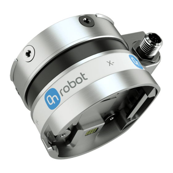
Page 20: Hex-E/H Qc
HW INSTALLATION 4.2.4. HEX-E/H QC HEX-E/H QC 1. HEX-E/H QC sensor 2. M4x6mm (ISO14581 A2) 3. M6x8mm (DIN7984LT A2) 4. HEX-E/H QC adapter 5. Adapter/ Robot tool flange (ISO 9409-1-50-4-M6) Use 1.5 Nm tightening torque for M4x6mm Use 3.8 Nm tightening torque for M6x8mm 4.2.5. -
Page 21: Rg2
HW INSTALLATION 4.2.5.2. RG2 Step 1: Move the tool close to the Quick Changer as illustrated. The hook mechanism (rod and hook tongue) will keep the lower part locked once mounted. Step 2: Flip the tool until it is fully mated, and you hear a clicking sound. -
Page 22: Rg2-Ft
HW INSTALLATION 4.2.5.3. RG2-FT Step 1: Move the tool close to the Quick Changer as illustrated. The hook mechanism (rod and hook tongue) will keep the lower part locked once mounted. Step 2: Flip the tool until it is fully mated, and you hear a clicking sound. -
Page 23: Rg6
HW INSTALLATION 4.2.5.4. RG6 Step 1: Move the tool close to the Quick Changer as illustrated. The hook mechanism (rod and hook tongue) will keep the lower part locked once mounted. Step 2: Flip the tool until it is fully mated, and you hear a clicking sound. -
Page 24: Screwdriver
HW INSTALLATION 4.2.5.5. Screwdriver Step 1: Move the tool close to the Quick Changer as illustrated. The hook mechanism (rod and hook tongue) will keep the lower part locked once mounted. Step 2: Flip the tool until it is fully mated, and you hear a clicking sound. -
Page 25: Vg10
HW INSTALLATION 4.2.5.7. VG10 Step 1: Move the tool close to the Quick Changer as illustrated. The hook mechanism (rod and hook tongue) will keep the lower part locked once mounted. Step 2: Flip the tool until it is fully mated, and you hear a clicking sound. -
Page 26: Wiring
HW INSTALLATION 4.3. Wiring The two operation modes require different wiring. DANGER: Use only original OnRobot tool data cables. Via Tool Connector This operation mode can be used with only one of these devices: 3FG15 (Only for e-Series) • RG2 / RG6 •... -
Page 27: Tool Data Cable
HW INSTALLATION DANGER: Never connect the Quick Changer or Dual Quick Changer to a CB3 UR robot's tool connector. Wiring via Tool Connector is finished. Via Compute Box Three cables need to be connected to wire the system properly: Tool data cable between the tool(s) and the Compute Box •... -
Page 28: Hex-E/H Qc
Finally, connect the other end of the Tool data cable to the Compute Box's DEVICES connector. CAUTION: Quick Changer and Dual Quick Changer can only be used to power OnRobot tools. 4.3.1.2. HEX-E/H QC First connect the data cable to the tool. -
Page 29: Rg2-Ft
CAUTION: Quick Changer and Dual Quick Changer can only be used to power OnRobot tools. 4.3.1.3. RG2-FT First connect the data cable to the tool. For RG2-FT the Quick Changer tool data connector cannot be used. Instead use the marked M8-4pin connector. -
Page 30: Ethernet Cable
Finally, connect the other end of the Tool data cable to the Compute Box's DEVICES connector. CAUTION: Quick Changer and Dual Quick Changer can only be used to power OnRobot tools. 4.3.2. Ethernet Cable Connect one end of the supplied Ethernet (UTP) cable to the robot controller's Ethernet (LAN) port. NOTE: If the robot controller's Ethernet port is in use, use a standard 4-port Ethernet switch to be able to use two network devices at the same time. -
Page 31: Power Supply
To disconnect the power connector, make sure to pull the connector housing (where the arrows are shown) and not the cable. CAUTION: Use only original OnRobot power supplies. Finally, power up the power supply that will power the Compute Box and the connected Tool(s). -
Page 32: Sw Installation
5.6 is not recommended, the 3.12 is not recommended. instead please use the 5.7. 1. Insert the OnRobot USB drive in the USB 1. Insert the OnRobot USB drive in the USB slot on the right side of the Teach Pendant. -
Page 33: Uninstall Software
URCaps option. screen), then from the System section tap on the URCaps menu. 2. Select the OnRobot URCap file. 2. Select the OnRobot URCap file. 3. Tap on the - sign. 3. Tap on the - sign. -
Page 34: Urcap Setup
5.3. URCap Setup For the e-Series UR robots, tap on the Installation tab in the top menu. Then tap on the URCaps. For the CB3 UR robots select the Installation tab, then select OnRobot Setup. The following screen is shown:... - Page 35 SW INSTALLATION Device info In the normal view of the panel, the available functions are shown below:...
- Page 36 1. Press the General dropdown menu on the left side. 2. Press the Tool IO tab. 3. In the Controlled by dropdown menu select OnRobot as shown in the image below. 4. Make sure to save the changes to be part of the current installation.
- Page 37 To communicate through the tool connector on CB3 UR robot please set the following configuration: 1. Go to the I/O tab. 2. In the Controlled by dropdown menu select OnRobot as shown in the image below. 3. Make sure to save the changes to be part of the current installation.
- Page 38 If the Tool connector option is selected in the Device info drop-down menu but no OnRobot product is connected to the tool connector then a background service program is running every 2 seconds. In addition to that the Tool IO is set to be logic high and low randomly.
-
Page 39: 3Fg15
SW INSTALLATION Device info The Selected IP address, Compute Box Versions, UR Robot IP and UR Robot subnet mask are shown. Errors This displays information about the errors if there is any. Device name The Serial number, System health and Firmware version are shown. Update: this will update the firmware if an update is available. - Page 40 SW INSTALLATION Mounting In the normal view of the panel, the selected Position is shown. Different Mounting Positions will allow to achieve different diameters and forces. Find more information in section Gripping Force and different Gripping Diameter. To select a different Mounting Position press on...
- Page 41 SW INSTALLATION NOTE: The new selected Mounting Position will be saved in the gripper and not in the installation file. Therefore, if the gripper is moved to another robot, the settings will remain the same. However, if another gripper is used in the same robot the settings might need to be reset again.
-
Page 42: Hex
6.4. TCP Configuration section. TCP offset Set the Linear offset (X,Y,Z) and the Rotation in RPY (Roll-Pitch-Yaw) values to adjust the OnRobot device dependent calculated TCP. 5.3.2. HEX The configuration panels for the HEX are shown in the image below:... - Page 43 SW INSTALLATION Hand Guide Require holding Hand Guide button: If checked (recommended) the Hand Guide enable button needs to be pressed constantly during the hand guiding. If unchecked, the hand guiding could be started by pressing the enable button and stopped by pressing the enable button again.
-
Page 44: Rg2-Ft
6.4. TCP Configuration section. TCP offset Set the Linear offset (X,Y,Z) and the Rotation in RPY (Roll-Pitch-Yaw) values to adjust the OnRobot device dependent calculated TCP. 5.3.3. RG2-FT The configuration panels for the RG2-FT are shown in the image below:... - Page 45 SW INSTALLATION Hand Guide Require holding Hand Guide button: If checked (recommended) the Hand Guide enable button needs to be pressed constantly during the hand guiding. If unchecked, the hand guiding could be started by pressing the enable button and stopped by pressing the enable button again.
- Page 46 SW INSTALLATION Proximity offset In the normal view of the panel, the set values are shown. To change the values, press on and the following screen will show: Calibrated value: shows the value to use for the application. This value is calculated as the Raw value minus the Offset value.
- Page 47 SW INSTALLATION Offset value: shows the value that, after calibration, will compensate the Raw value to have usable Calibrated value. Calibration To calibrate the proximity sensor, follow the steps below. 1. Prepare a white paper and tap on Set proximity offset. 2.
-
Page 48: Rg2/6
6.4. TCP Configuration section. TCP offset Set the Linear offset (X,Y,Z) and the Rotation in RPY (Roll-Pitch-Yaw) values to adjust the OnRobot device dependent calculated TCP. 5.3.4. RG2/6 The configuration panels for the RG2/6 are shown in the image below:... - Page 49 SW INSTALLATION In the normal view of the panel the TCP of the robot can be overwritten by the TCP of the tool by pressing the Automatic overwrite of the robot TCP configuration checkbox. To see more options press on and the following screen will show: Overwrite values...
- Page 50 TCP offset Set the Linear offset (X,Y,Z) and the Rotation in RPY (Roll-Pitch-Yaw) values to adjust the OnRobot device dependent calculated TCP. Mounting In the normal view of the panel, the selected mounting angle is shown. To set the mounting angle press on If only one gripper is mounted, follow the steps bellow.
-
Page 51: Screwdriver
SW INSTALLATION 1. When looking at the grippers, make sure that the Quick Changer is orientated with the part 1 on the left side and the part 2 on the right side . The numbers are written on the side of the Quick Changer that connects to the robot. 2. - Page 52 6.4. TCP Configuration section. TCP offset Set the Linear offset (X,Y,Z) and the Rotation in RPY (Roll-Pitch-Yaw) values to adjust the OnRobot device dependent calculated TCP. 5.3.6. SG The configuration panels for the SG are shown in the image below:...
- Page 53 SW INSTALLATION SG Tool Setup In the normal view of the panel, the Saved tool can be seen. If there is a mismatch between the Saved tool and the Current initialized tool, the Current tool will be shown and this will appear in the top right corner of the card.
- Page 54 SW INSTALLATION When choosing a tool, in the dropdown menu, the gripper will automatically initialize to the chosen tools neutral position. This will also automatically set the right tool operating parameters such as width, TCP and tool Center of Mass. The gripper can also be initialized by pressing the Initialize button in the toolbar.
-
Page 55: Vg10
TCP offset Set the Linear offset (X,Y,Z) and the Rotation in RPY (Roll-Pitch-Yaw) values to adjust the OnRobot device dependent calculated TCP. 5.3.7. VG10 In the normal view of the panel the TCP of the robot can be overwritten by the TCP of the tool by pressing the Automatic overwrite of the robot TCP configuration checkbox. -
Page 56: Vgc10
6.4. TCP Configuration section. TCP offset Set the Linear offset (X,Y,Z) and the Rotation in RPY (Roll-Pitch-Yaw) values to adjust the OnRobot device dependent calculated TCP. 5.3.8. VGC10 The configuration panels for the VGC10 are shown in the image below:... - Page 57 SW INSTALLATION Attachment In the normal view of the panel, the selected attachment types such as Standard, Pipe + Cup, Adaptor + Cups, Adaptor + Pipe + Cup and For customization are mentioned. This configuration panel is used to set the TCP in the right position as well as to move the Center of Gravity of the workpiece to the new TCP.
- Page 58 SW INSTALLATION Here the actual mounting can be selected to set up the TCP correctly. The different options are: Standard: Device with only four cups attached to it. This selection will set the TCP at the • center of the end side of the cups (see table below). Pipe + Cup: Device with the extension pipe with a cup placed in the right side using the •...
- Page 59 SW INSTALLATION Attachment TCP (x, y, z) [mm] Image Standard (0, 0, 100) Pipe + Cup (-17, 17, 150) Adaptor + Cups (0, 0, 110) Adaptor + Pipe + Cup (0, 0, 160) For customization (0, 0, 75)
- Page 60 SW INSTALLATION The TCP values have their origin in the top part of the gripper as shown in the image below. In the normal view of the panel the TCP of the robot can be overwritten by the TCP of the tool by pressing the Automatic overwrite of the robot TCP configuration checkbox.
- Page 61 SW INSTALLATION Set the Linear offset (X,Y,Z) and the Rotation in RPY (Roll-Pitch-Yaw) values to adjust the OnRobot device dependent calculated TCP.
-
Page 62: Operation
URScript commands - can be used alongside other scripts. • NOTE: OnRobot functions only accept input and returns output in metric units. If you have values to provide in US Standard units, use the following conversion rates. US Standard... -
Page 63: 3Fg15
OPERATION 6.1.1. 3FG15 3FG Grip When the 3FG Grip command is executed, the gripper will try to reach the specified target (Diameter and Force). The different functions are explained below. The command name in the robot program shows bullets • and a number in parenthesis (X). •(x)•... - Page 64 OPERATION Diameter: The target gripping diameter can be set by using the Save as Target button (recommended) or by typing it in manually. The external gripper diameter will be shown if grip internally is selected and the internal gripper diameter will be show if grip externally is selected.
- Page 65 OPERATION State Feedback image Internal grip with target force detected Current diameter The number shows the Current diameter value. will set: the Target Diameter as Current diameter – 3 mm if grip workpiece is selected. • the Target Diameter as Current diameter + 3 mm if grip workpiece is selected.
- Page 66 OPERATION The command name in the robot program shows bullets • and a number in parenthesis (XX). •(xx)• Bullets outside the parenthesis means external release • (•xx•) Bullets inside the parenthesis means internal release • The number in parenthesis shows the target diameter •...
-
Page 67: Hex-E/H Qc
OPERATION will set the Current diameter as target diameter. These are open and close hold-to-run buttons. 6.1.2. HEX-E/H QC F/T Control Applications such as polishing, deburring, sanding or grinding may require holding constant force/torque to a defined direction during movements. This command alters the trajectory of its child node(s) in order to keep the force/torque values constant along/about the selected axes. - Page 68 OPERATION Compliant axis Fx, Fy, Fz, Tx, Ty, Tz: The axis selection that needs to be compliant. If an axis is enabled (compliant) the movement along/about that axis is force/torque controlled otherwise (non-compliant) position controlled. The enabled axis is controlled to keep the set force/torque value constant.
- Page 69 OPERATION The PID force/torque controller continuously calculates the error value for the force/torque measured by the sensor, compared to the values set by the command, and F/T Control applies correction based on this error. P gain F and P gain T: The proportional term produces a correction that is proportional to the current error value.
- Page 70 OPERATION To operate the command tap on the Add {{ waypoint.title }} button to add an F/T Move as a child node. More waypoints can be added in the same way. To remove a Waypoint waypoint, use the Structure tab Delete button. Alternatively, could be added as a child node of the F/T Waypoint...
- Page 71 OPERATION F/T Limit Fx,Fy,Fz,Tx,Ty,Tz,F3D,T3D: If any of the values reach the set threshold the stop is triggered. Values equal to zero are neglected. More than one option can be set. If the Use absolute values option is enabled, then it is not important whether the entered value is positive or negative (e.g.: |Fz| >...
- Page 72 OPERATION Type: If relative is selected, the Path is replayed starting from the actual position of the Tool, instead of the absolute position where it was recorded. If absolute is selected, the Tool moves to the original starting point, and replays the Path from there. Path ID:: Lists identifiers of all the Paths saved on the Compute Box.
- Page 73 OPERATION Stop Path Replay: Stops replaying the Path. Save Path: Saves the Unsaved Path to the Compute Box. NOTE: The robot speed must always be 100%, replaying at lower speed can create a significant deviation from the recorded trajectory. NOTE: Rotational movements related to translational movements in Path recording are limited to 2.8 degrees/mm or less, since a larger ratio would cause the Robot to replay the path at a very low translational speed.
- Page 74 OPERATION To operate the command tap on the Add Waypoint button to add an F/T Search as a child node. More waypoints can be added in the same way. To remove a Waypoint waypoint, use the Structure tab Delete button. Alternatively, could be added as a child node of the F/T Waypoint...
- Page 75 OPERATION coordinate system, by the orientation of the current TCP. To test the given orientation, the Rotate tool to this orientation [HOLD] button can be used. Halt program execution if limit has not been reached: If enabled, then the program execution will be stopped when the target position is reached or was already in collision (so the search is not successful).
- Page 76 OPERATION Move robot to pose [HOLD]: moves the robot to the pose set in the Target TCP pose field, if the button is pressed. Once it is released the robot stops. Variable: The position represented by the waypoint in the robot route. A variable can define the target pose.
- Page 77 OPERATION F/T Zero command can be used to zero the force/torque values. F/T Zero This command has no return value. F/T Guard Every UR commands that are put under the will be executed, but the robot will F/T Guard stop once one of the set limits is reached. The force limiting can be mixed with an external I/O signal (e.g.: stop if Fz>5 AND digital_in[7] == True NOTE:...
- Page 78 OPERATION Coordinate system: The coordinate system used both for the movement and for the sensor reading. It can be set to Base or Tool (according to the UR’s reference frames). F/T Limit: This is the detection limit. From the Fx, Fy, Fz, Tx, Ty, Tz, F3D, T3D available options more than one can be set.
- Page 79 OPERATION If the In addition to the force/torque limits, stop if is enabled, then the set digital I/O will also be monitored and once the condition is met (along with the force/torque limit) the robot will be stopped. (e.g.: stop if Fz>5 AND digital_in\[7\] == True This command has no return value, and halts the program when limits are reached.
- Page 80 OPERATION Pushing force: The force target used for the force control to gently push the part into the hole. Min depth: The minimum distance required to consider the insertion successful, from the starting point along the Z axis (in Tool coordinate system). Max depth: The maximum distance the insertion can reach, from the starting point along the Z axis (in Tool coordinate system).
- Page 81 OPERATION Gain of force: The proportional gain parameter of the force control for the pushing force, and the side forces on compliant axes. Gain of torque: The proportional gain parameter of the torque control for the compliant axes. NOTE: High gain values can result vibration and protective stop. Higher mass and bigger distance can be vibrating more easily.
-
Page 82: Rg2-Ft
OPERATION TCP offset Set the Linear offset (X,Y,Z) and the Rotation in RPY (Roll-Pitch-Yaw) values to adjust the OnRobot device dependent calculated TCP. Payload Modify Tool payload: If enabled the UR's payload will be overwritten. enter the workpiece mass that is attached to the device. The device own mass is added automatically. - Page 83 OPERATION NOTE: To cancel any force/torque offset, execute an command at the F/T Zero beginning of the command and make sure the gripper is not in RG Grip contact with any object before starting the , otherwise the F/T Width command may not work properly.
- Page 84 OPERATION Current width The number shows the Current width value. will set the Current width as target width. If used when a grasp is detected (see image below) this will set the Target Width as Current width – 3 mm if the workpiece is grabbed externally and + 3 mm if the workpiece is grabbed internally.
- Page 85 OPERATION If the Set part TCP checkbox is checked the TCP will be set at the further end of the part. It requires the following two parameters to be given: Part length (L): the distance between the center point of the fingertip sensors and the center point of the item to be inserted.
- Page 86 OPERATION Gain of force: The proportional gain parameter of the force control for the side forces on compliant axes. Gain of torque: The proportional gain parameter of the torque control for the compliant axes. Gain of force (Z): The proportional gain parameter of the force control for the pushing force. Gain of torque (Z): The proportional gain parameter of the torque control parallel to the insertion direction.
- Page 87 OPERATION Generate warning when insertion unsuccessful: If enabled, a pop-up message (blocking) appears if the insertion was not successful. NOTE: The option is only active when a valid limit has been set at the advanced screen. If disabled, then no pop-up message is shown but the user can handle any possible errors by the return value of the command.
- Page 88 OPERATION Compliant axis Fx, Fy, Fz, Tx, Ty, Tz: The axis selection that needs to be compliant. If an axis is enabled (compliant) the movement along/about that axis is force/torque controlled otherwise (non-compliant) position controlled. The enabled axis is controlled to keep the set force/torque value constant.
- Page 89 OPERATION I gain F: The force controller can be tuned with this integral gain parameter. If any overshoots or vibrations occur, try lowering the gain value. I gain T: The torque controller can be tuned with this integral gain parameter. If any overshoots or vibrations occur, try lowering the gain value.
- Page 90 OPERATION If the force control is overreacting to changes, that is, the tool bounces off the surface, try decreasing the P gain F and P gain T (or D gain F and D gain T, if it is above 1). If the force control is reacting to changes too slowly, that is it keeps pushing the surface hard after touching it, try decreasing the I Gain.
- Page 91 OPERATION To operate the command tap on the Add {{ waypoint.title }} button to add an F/T Move as a child node. More waypoints can be added in the same way. To remove a Waypoint waypoint, use the Structure tab Delete button. Alternatively, could be added as a child node of the F/T Waypoint...
- Page 92 OPERATION no pop-up message is shown but the user can handle any possible errors using the return value of the command. See return values in the 6.5. Return Values section. F/T Path command can be used together with the command, F/T Path F/T Move F/T Search...
- Page 93 OPERATION Start Path Recording: Starts recording a Path by automatically enabling the Hand Guide function. Stop Path Recording: Stops the Hand Guide function and stores the recording to the memory. It does not permanently save the Path. Move to Path Starting Point [HOLD]: Moves the Tool to the starting position of the Path, it can only be used if the path is not relative.
- Page 94 OPERATION To operate the command tap on the Add Waypoint button to add an F/T Search as a child node. More waypoints can be added in the same way. To remove a Waypoint waypoint, use the Structure tab Delete button. Alternatively, could be added as a child node of the F/T Waypoint...
- Page 95 OPERATION coordinate system, by the orientation of the current TCP. To test the given orientation, the Rotate tool to this orientation [HOLD] button can be used. Halt program execution if limit has not been reached: If enabled, then the program execution will be stopped when the target position is reached or was already in collision (so the search is not successful).
- Page 96 OPERATION Move robot to pose [HOLD]: moves the robot to the pose set in the Target TCP pose field, if the button is pressed. Once it is released the robot stops. Variable: The position represented by the waypoint in the robot route. A variable can define the target pose.
- Page 97 OPERATION F/T Zero command can be used to zero the force/torque values. F/T Zero This command has no return value. command is used to set the current TCP and/or payload for the robot.
-
Page 98: Rg2/6
OPERATION TCP offset Set the Linear offset (X,Y,Z) and the Rotation in RPY (Roll-Pitch-Yaw) values to adjust the OnRobot device dependent calculated TCP. Payload Modify Tool payload: If enabled the UR's payload will be overwritten. enter the workpiece mass that is attached to the device. The device own mass is added automatically. - Page 99 OPERATION When pressed, the gripper will act as if the command is executed. Force: Set the target gripping Force (3-40 N for the RG2 and 25-120 N for the RG6). Depth compensation: During closing and opening the gripper, the robot moves to compensate for the circular movement of the fingers, so that the fingertips remain on the target.
-
Page 100: Screwdriver
TCP and/or payload for the robot. TCP offset Set the Linear offset (X,Y,Z) and the Rotation in RPY (Roll-Pitch-Yaw) values to adjust the OnRobot device dependent calculated TCP. Payload Modify Tool payload: If enabled the UR's payload will be overwritten. - Page 101 OPERATION Target Screw length: Input the length of the screw. When pressed, the screwdriver will act as if the command is executed. Check results Selecting one of the 2 options from the dropdown list and pressing Insert will add an if statement in the robot program based on the selected option as shown in the screenshot below.
-
Page 102: Tighten Screw
OPERATION NOTE: The screwdriver's bit should be at least 50 mm away from the picking point until the screw is waiting in place. Otherwise, the magnetic force of the Screw- bit System will attract the screw sidewise and it might cause a misalignment between the screw and the bit. -
Page 103: Loosen Screw
OPERATION Check results Selecting one of the 3 options from the dropdown list and pressing Insert will add an if statement in the robot program based on the selected option. The Dropdown list options are: Process successful: Uses the function get_sd_Process_OK() and returns true if the •... - Page 104 OPERATION Target Unscrewing length = A-B-C: The resulting unscrewing length is shown here. This is the amount of the screw that will be unscrewed from the thread. To set the value use the Set unscrewing length card and the resulting amount will be the A (screw length) - B (Washer thickness) - C (Chamfer deepness).
-
Page 105: Move Shank
OPERATION A = This is the screw length, distance from the screw bit to the bottom part of the screw head. B = This is the washer thickness (or piece in between screw and thread), if no piece is used set it as 0. -
Page 106: Tcp
TCP and/or payload for the robot. TCP offset Set the Linear offset (X,Y,Z) and the Rotation in RPY (Roll-Pitch-Yaw) values to adjust the OnRobot device dependent calculated TCP. Payload Modify Tool payload: If enabled the UR's payload will be overwritten. - Page 107 OPERATION Center of gravity CX, CY, CZ: set the location of the center of gravity of the workpiece. 6.1.6. SG SG Grip / SG Release command is used to grip or release a workpiece. SG Grip/SG Release When the command is executed, the gripper will try to reach the SG Grip/SG Release specified target Width, moving by the default Gentle grip speed, and if selected, Depth compensation.
- Page 108 OPERATION NOTE: Gentle grip and Workpiece options are only available in the SG Grip command. Select device If two SG grippers are connected, select whether it is the SG (1) or SG (2) that performs the action Target Width: The target gripping width can be set by using the Save as Target/Save Grasp button (recommended) or by typing it in manually.
-
Page 109: Vg10/Vgc10
TCP and/or payload for the robot. TCP offset Set the Linear offset (X,Y,Z) and the Rotation in RPY (Roll-Pitch-Yaw) values to adjust the OnRobot device dependent calculated TCP. Payload Modify Tool payload: If enabled the UR's payload will be overwritten. - Page 110 OPERATION When 2 grippers are used, the radio buttons Gripper 1 and Gripper 2 will appear. These buttons will select which one of the 2 grippers performs the action. In the robot program, the command name will show [1] or [2] to indicate which grippers is performing the action. Channel(s): Select which channel perform the action.
- Page 111 OPERATION NOTE: In order to help the Auto-level part to function, make sure to use the same suction caps for A and B channels and set the arms to be symmetrical. When any of the VG grippers is used without a HEX-E/H QC but used on an E-series controller the following extra option becomes available: Seek: when checked, the same seeking action will happen as above.
- Page 112 TCP and/or payload for the robot. TCP offset Set the Linear offset (X,Y,Z) and the Rotation in RPY (Roll-Pitch-Yaw) values to adjust the OnRobot device dependent calculated TCP. Payload Modify Tool payload: If enabled the UR's payload will be overwritten.
-
Page 113: Urcap Toolbar
Then press on the OnRobot icon Each OnRobot End of Arm Tooling has its own functionality and that is explained in the sections below. To open up the toolbar in the CB3, press on the OnRobot icon on the top left side. - Page 114 OPERATION To enable/disable the toolbar, press on the OnRobot logo on the top right corner and check/uncheck the Enable toolbar checkbox.
-
Page 115: 3Fg15
OPERATION 6.2.1. 3FG15 To open up the toolbar follow the instructions in the How to Access the Toolbar section. The toolbar for the 3FG15 gripper is shown below. -
Page 116: Hex-E/H Qc
OPERATION Current internal diameter. Current external diameter. These are open and close hold-to-run buttons. 6.2.2. HEX-E/H QC To open up the toolbar follow the instructions in the How to Access the Toolbar section. The toolbar for the HEX is called Hand Guide and it is shown below. This toolbar is used to hand guide the robot by holding the End of Arm Tooling with your hand. - Page 117 OPERATION The toolbar contains the available axes, the enable button , the zero button and the snap to axes button To select an axis, tap on the appropriate item. An axis is selected if it turns from white to blue In the following example, the X and the Y items are selected to limit the movement along the X and Y axis (planar): NOTE:...
-
Page 118: Rg2-Ft
OPERATION while the hand guiding is being initiated. Wait until the enable button turns blue and drive the robot by hand with the help of the OnRobot sensor. NOTE: Make sure that you do not touch the tool before the hand guiding is activated... - Page 119 OPERATION Current width: shows how wide the gripper is opened. Force: Set the target gripping force. : These are open and close hold-to-run buttons. The toolbar for hand guiding is shown below.
- Page 120 Wait until the enable button turns blue and drive the robot by hand with the help of the OnRobot sensor. NOTE: Make sure that you do not touch the tool before the hand guiding is activated...
-
Page 121: Rg2 / Rg6
OPERATION NOTE: The hand guiding could be configured (in the OnRobot installation page) to be enabled with a single tap on the enable button (instead of holding) and stopped with a second tap. However, the holding behavior is recommended for increased safety. -
Page 122: Screwdriver
NOTE: To operate, - when connected via the Tool Connector - the Tool IO must set to be controlled by OnRobot. 6.2.5. Screwdriver To open up the toolbar follow the instructions in the How to Access the Toolbar section. - Page 123 OPERATION Torque feedback Current torque: show the current torque the screwdriver is applying at the moment. Achieved torque: shows the achieved torque on the last command executed. Tighten Shank position Current: shows the current position of the shank. Target: changes the position of the shank immediately. The target position can also be set by using the input field above the slider.
-
Page 124: Vg10 / Vgc10
OPERATION GS (1) and GS (2): In case of using 2 SG grippers, you can select which one performs the action. Current width: shows the value. These are open and close hold-to-run buttons. This is for homing the SG. Initialize: Press here to initialize the gripper with the current tool. This button will only appear if the gripper is not initialized or if there is a mismatch between the Saved and the Current tool. -
Page 125: Urscript Commands
6.3. URScript Commands URScript commands can be used alongside other scripts. 6.3.1. 3FG15 When the OnRobot URCap is enabled, there will be several 3FG script functions available: tfg_grip(diameter, force, external_grip= True, stop_if_no_force =true, tool_index=0, blocking=True) : The diameter that the gripper will open to. [mm] diameter : The force that the gripper will try to reach. -
Page 126: Rg2-Ft
(3fg_Diameter_primary+5, 2) -> for secondary 6.3.2. RG2-FT When the OnRobot URCap is enabled, there will be a defined RG2-FT script function: rg2ft_proxi_offsets_set(ProxL = 0.0, ProxR = 0.0) This function can be used to manually set offset values of the optical (proximity) finger sensor. -
Page 127: Rg2/Rg6
OPERATION 6.3.3. RG2/RG6 When the OnRobot URCap is enabled, there will be a defined RG script function: rg_grip(rg_width, force, tool_index=0, blocking=True, depth_compensation=False, popupmsg=True) Blocking=True: the function waits for the gripper to finish the grip command (popupmsg: future function, do not need to fill) - Page 128 : Provides the current measured torque • get_sd_Current_torque() 6.3.5. SG When the OnRobot URCap is enabled, there will be several SG script functions available: sg_grip(target_width, gentle_grip, tool_index=0, blocking=True, depth_compensation=False) : The width that the gripper will open to. [mm] target_width...
-
Page 129: Vg10/Vgc10
OPERATION sg_release(target_width, tool_index=0, blocking=True, depth_compensation=False) : The width that the gripper will open to. [mm] target_width : The index of the gripper to send the command to. tool_index =True: the function waits for the gripper to finish the grip command. blocking =False: The robot will move during the release to compensate for the depth_compensation... - Page 130 OPERATION for primary tool_index=1 for secondary tool_index=2 vg10_release(channel, timeout, autoidle, tool_index) Commands the VG10 to perform a release. : Tells which channel to be released. channel 0 = Channel A 1 = Channel B 2 = Channel A and Channel B If not set, this parameter defaults to 2 (A and B).
-
Page 131: Tcp Configuration
Waypoints according to the Active TCP. For further info about the UR's TCP handling read the UR's Manual. How “far” the TCP needs to be moved to be at the “end” of the OnRobot tools could be found in the 8.3. COG, TCP section. - Page 132 However, it is highly recommended to create the Waypoints in the UR's Move command in a way that the referencing TCP is set first. So, if only a single OnRobot device is used, before the Waypoints are defined, set the UR's Move command's TCP to use the OnRobot_Single.
- Page 133 OPERATION If two OnRobot devices are used, select OnRobot_Dual_1 or OnRobot_Dual_2 accordingly. If not the UR's Move command but the OnRobot command is used (for HEX-E/H QC F/T Move or RG2-FT only): Use the OnRobot TCP command just before the to set the Active TCP to the •...
- Page 134 Before you teach any Waypoint make sure to set the Active TCP beforehand: for Single device go to the OnRobot Installation panel • for Dual devices go to the OnRobot Installation panel and Select the Device (1 or 2) that • you are using at the time of the teaching...
-
Page 135: Return Values
MoveJ (Set TCP = Active TCP) TCP (Select Gripper 2) MoveJ (Set TCP = OnRobot_Dual_2) 6.5. Return Values Those OnRobot commands that has return values updates the variable once the on_return command exit. This global variable can be used with the UR’s built in... -
Page 136: Feedback Variables
F/T Insert Part command. 6.6. Feedback Variables 6.6.1. 3FG15 Feedback Variable Unit Description on_return The return value for the OnRobot commands tfg_Busy True/false Whether the gripper is active or not tfg_Diameter [mm] Width between the fingers of the Gripper tfg_Grip_detected... -
Page 137: Hex-E/H Qc
6.6.2. HEX-E/H QC Feedback Unit Description Variable on_return The return value for the OnRobot commands Length of the 3D force vector √ F3D = Fx² + Fy² + Fz² FT_Base [3xN,3xNm] Force and torque values calculated in the Base Coordinate... -
Page 138: Rg2 / Rg6
Length of the 3D torque vector √ T3D = Tx² + Ty² + Tz² Width [mm] Distance between the fingers of the Gripper (calculated by finger angle encoders) 6.6.4. RG2 / RG6 Feedback Variable Unit Description on_return The return value for the OnRobot commands... -
Page 139: Screwdriver
OPERATION Feedback Variable Unit Description rg_Busy True/false Whether the gripper is active or not rg_Depth [mm] Distance the robot (due to depth compensation) has moved towards the z axes having as reference the gripper at 0 mm width rg_DepthRel [mm] Distance the robot (due to depth compensation) has moved towards the z axes having as reference the previous gripper's width... -
Page 140: Vg10 / Vgc10
6.6.6. SG Feedback Unit Description Variable on_return The return value for the OnRobot commands sg_Busy True/false Whether the gripper is active or not sg_Depth [mm] Distance the robot (due to depth compensation) has moved towards the z axes having as reference the gripper at 0 mm... - Page 141 OPERATION Lines 8 -14: the command is executed. If the command is not successful, the Pick Screw robot will move to separate from the screw feeder and a popup will be displayed saying “Missing screws”. Else the robot program will continue. Lines 15 - 22: the robot moves form the screw feeder to the thread Lines 21 - 27: the command is executed.
-
Page 142: Additional Software Options
This interface could be used to communicate via simple digital I/O lines with the robots. There are 8 digital input and 8 digital output that could be used. These inputs and outputs can be programmed through the OnRobot WebLogic™ that requires the Ethernet interface to be used (only for programming time). - Page 143 Open a web browser on your computer and type in the IP address of the Compute Box • (factory default is 192.168.1.1). The Sign-in page opens: The factory default administrator login is: Username: admin Password: OnRobot For the first login a new password needs to be entered: (password must be at least 8 characters long)
-
Page 144: Web Client: Devices Menu
Configuration - Change the Compute Box's settings • • WebLogic™ - Program the Digital I/O interface through OnRobot WebLogic™ Paths - Import/export the recorded Paths (not available to all robots) • Update - Update the Compute Box and the devices •... -
Page 145: 3Fg15
ADDITIONAL SOFTWARE OPTIONS 7.1.3.1. 3FG15 The state of the gripper could be: Busy - the gripper is in motion • • Grip detected - the gripper has detected a workpiece Force grip detected - the gripper has applied the target force to a workpiece. This also •... - Page 146 ADDITIONAL SOFTWARE OPTIONS The gripper can be controlled by adjusting the Target raw diameter slider. The actual values of the fingers are shown by the Current raw diameter. The raw diameter is without the fingertip offset. In Grip mode: First set how to grip the part: Externally or •...
- Page 147 ADDITIONAL SOFTWARE OPTIONS Select finger position - Select the mounted finger position and Save. • Set finger length - If customized fingers are needed, the checkbox can be enabled, and • the new finger length can be entered. Set fingertip offset - The 4 different types that are delivered with the gripper can be •...
-
Page 148: Hex-E/H Qc
ADDITIONAL SOFTWARE OPTIONS 7.1.3.2. HEX-E/H QC The force and torque values (Fx,Fy,Fz and Tx,Ty,Tz) are shown in N/Nm. The Zero toggle switch can be used to zero the force and torque reading. NOTE: Zero value set on this page is not stored permanently and are restored to the default values on power reset. -
Page 149: Rg2/6
ADDITIONAL SOFTWARE OPTIONS 7.1.3.3. RG2/6 The state of the gripper could be: • Busy - the gripper is moving Grip detected - the set force limit is reached but the set width is not. • The status of the two safety switch shows: Pushed - the safety switch 1/2 is still being pushed •... -
Page 150: Rg2-Ft
ADDITIONAL SOFTWARE OPTIONS The gripper can be controlled by adjusting the Force and Width value. First set the required gripping force and then adjust the width slider that will immediately control the gripper. 7.1.3.4. RG2-FT The force and torque values (Fx,Fy,Fz and Tx,Ty,Tz) are shown in N/Nm along with the Proximity sensor values (optical distance sensor built in the fingertip) are show in mm for the left and right fingertip sensor. - Page 151 ADDITIONAL SOFTWARE OPTIONS NOTE: Zero value set on this page is not stored permanently and are restored to the default values on power reset. The Proximity offset can be used to calibrate the proximity reading. The calibration requires the following steps to be done: Write 0 mm to the Left and Right edit box and click on the Save button.
-
Page 152: Screwdriver
ADDITIONAL SOFTWARE OPTIONS 7.1.3.5. Screwdriver The state of the gripper: Torque - Shows the current torque. • Shank position - Shows the current shank position. • Busy - the screwdriver is in motion • • Safety triggered - shows if the mechanical safety is being trigger. Enable - Press to enable the screwdriver after the mechanical safety is being trigger. - Page 153 ADDITIONAL SOFTWARE OPTIONS Not screwing in • Timeout waiting for torque • • Torque exceeded prematurely Unable to loosen screw • Shank reached the end • Shank obstructed during move • Screwing parameters and functions: • Screw type - The screw sizes from M1.6 to M6 can be selected. This selection will autofill the standard torque value for that particular screw type.
- Page 154 ADDITIONAL SOFTWARE OPTIONS 7.1.3.6. SG The States of the gripper could be: Busy - the gripper is moving • Initialized - the gripper has been initialized. • Select tool type Current tool - Shows the currently selected SG tool. Select the desired SG tool, by clicking •...
-
Page 155: Vg10 / Vgc10
ADDITIONAL SOFTWARE OPTIONS The default gripping speed is set as Gentle grip, the gripping speed is reduced at 12.5mm before the specified target width, this results in a gentler grip, compared to normal grip settings. The gripper can be controlled by adjusting the Target width slider, this will immediately control the gripper. -
Page 156: Web Client: Configuration Menu
ADDITIONAL SOFTWARE OPTIONS Low power limit may not be enough for higher percentage of vacuum and the target vacuum level may not be reached. The Channel A and Channel B vacuum level can be set individually or in tandem by checking the Lock checkbox. -
Page 157: Web Client: Path Menu
ADDITIONAL SOFTWARE OPTIONS If it is set to Static IP, then a fixed IP address and subnet mask must be set. • If it is set to Default Static IP, the fixed IP revert to the factory default and cannot be •... -
Page 158: Web Client: Update Menu
ADDITIONAL SOFTWARE OPTIONS To import a previously exported Path (.ofp file) click on Import and browse for the file. The available Paths are listed at the end of the page. Any paths can be exported and downloaded as a .ofp file or permanently deleted to free up the list if a path is not needed anymore. - Page 159 ADDITIONAL SOFTWARE OPTIONS CAUTION: During the update process (takes about 5-10 minutes) DO NOT unplug any device or close the browser window. Otherwise the updated device could be damaged. The loading screens during the update process are the same for the software and the firmware updates.
-
Page 160: Web Client: Account Settings
ADDITIONAL SOFTWARE OPTIONS To start the firmware update, click on Update button in the firmware section of the page, see below. If the update is finished and was successful, the message below is shown. 7.1.7. Web Client: Account Settings This menu can be used to: See the currently sign-id user •... - Page 161 ADDITIONAL SOFTWARE OPTIONS On the Users tab click on the Add new user button to add more users:...
- Page 162 ADDITIONAL SOFTWARE OPTIONS There are three user levels: Administrator • Operator • User • Fill in the user information and click Save. Later on to change any user information just click on the edit icon.
- Page 163 ADDITIONAL SOFTWARE OPTIONS To prevent a user to sign-in either could be: deactivated by changing its Active status in the edit mode • or removed by clicking the delete icon. •...
-
Page 164: Hardware Specification
HARDWARE SPECIFICATION 8. Hardware Specification 8.1. Technical Sheets 8.1.1. 3FG15 General Properties Minimum Typical Maximum Unit [kg] [lb] Payload Force Fit [kg] [lb] Payload Form Fit [mm] 0.16 5.98 [inch] External Grip Diameter* [mm] 1.38 6.93 [inch] Internal Finger position resolution [mm] 0.004 [inch]... - Page 165 HARDWARE SPECIFICATION Operating Conditions Minimum Typical Maximum Unit Power supply Current consumption 1500* [mA] Operating temperature [°C] [°F] Relative humidity (non-condensing) Calculated MTBF (operating life) 30.000 [Hours] *600 mA set as default. Fingers The supplied fingers can be mounted in 3 different positions to achieve different Gripping Forces and different...
- Page 166 HARDWARE SPECIFICATION Fingertips The supplied fingertips are listed below. Different fingertips will allow to achieve different Gripping Forces and different Gripping Diameters. • Ø10 mm steel Ø13 mm steel • Ø13.5 mm silicone • Ø16.5 mm silicone • If custom fingertips are required, they can be made to fit the Gripper’s fingers according to the dimensions (mm)[inch] shown below.
- Page 167 HARDWARE SPECIFICATION In the graph below, the maximum payload allowed for customized fingertip given a length is shown.
- Page 168 HARDWARE SPECIFICATION In the graph below, how the % of maximum achievable force decreases as the finger length increases when customized fingertips are used. X-shape fingertips These fingertips improve the gripper's ability to pick and place round workpieces with collar like features.
- Page 169 HARDWARE SPECIFICATION Gripping Force The total gripping force highly depends on the finger angle θ. For both internal and external grip, the lower the finger angle, the higher the force that will be applied as shown in the graph below. Although the fingers can move from 0 to 180, the angle range of an external grip is 30º-165º...
-
Page 170: Hex-E Qc
Angle for internal gripping min 160º and max 30º • The closer to the maximum diameter range, the lower the angle and, therefore, the higher the force. 8.1.2. HEX-E QC General Properties 6-Axis Force/Torque Sensor Unit Nominal Capacity (N.C) [N] [Nm] Single axis deformation at N.C (typical) - Page 171 HARDWARE SPECIFICATION General Properties 6-Axis Force/Torque Sensor Unit Full scale nonlinearity < 2 < 2 < 2 < 2 Hysteresis (measured on Fz axis , typical) < 2 < 2 < 2 < 2 Crosstalk (typical) < 5 < 5 <...
-
Page 172: Hex-H Qc
HARDWARE SPECIFICATION 8.1.3. HEX-H QC General Properties 6-Axis Force/Torque Sensor Unit Nominal Capacity (N.C) [N] [Nm] Single axis deformation at N.C (typical) ± 0.6 ± 0.25 ± 2 ± 3.5 [mm] [°] ± 0.023 ± 0.009 ± 2 ± 3.5 [inch] [°] Single axis overload Signal noise* (typical) -
Page 173: Quick Changers
HARDWARE SPECIFICATION 8.1.4. Quick Changers If not specified, the data represent the combination of the different Quick Changer types/ sides. Technical data Typical Units Permissible force * 400* Permissible torque * [Nm] Rated payload * [kg] [lbs] Repeatability ±0.02 [mm] IP Classification Operating life (Tool change) 5.000... -
Page 174: Rg2
HARDWARE SPECIFICATION Load Capacity - Static - Acceleration 2g - Acceleration 4g 8.1.5. RG2 General Properties Minimum Typical Maximum Unit [kg] [lb] Payload Force Fit [kg] [lb] Payload Form Fit Total stroke (adjustable) [mm] 4.33 [inch] Finger position resolution [mm] 0.004 [inch] Repetition accuracy... - Page 175 HARDWARE SPECIFICATION General Properties Minimum Typical Maximum Unit Gripping force (adjustable) Gripping force deviation ±25 Gripping speed * [mm/s] Gripping time ** 0.06 0.21 Adjustable bracket tilting accuracy < 1 ° Storage temperature [°C] [°F] Motor Integrated, electric BLDC IP Classification IP54 Dimensions 213 x 149 x 36...
- Page 176 HARDWARE SPECIFICATION RG2 Gripping Speed Graph RG2 Work Range Gripping on long objects can unintentionally activate the Safety switches. The maximum workpiece height (calculated from the end of the fingertips) is dependent on the gripping width (w). For various width values the height (h) limit is given below:...
- Page 177 HARDWARE SPECIFICATION Fingertips The standard fingertips can be used for many different workpieces. If custom fingertips are required, they can be made to fit the Gripper’s fingers according to the dimensions (mm) shown below:...
- Page 178 HARDWARE SPECIFICATION X-Shaped fingertips These fingertips improve the gripper's ability to pick and place cylindrical workpieces. By combining the force fit and the form fit gripping approaches, the fingertips increase the stability and payload of the workpiece to be gripped. These fingertips are an accessory and need to be purchased separately.
-
Page 179: Rg2-Ft
HARDWARE SPECIFICATION RG2 fingertip extension 100 mm PN 105873 • 8.1.6. RG2-FT General Properties Minimum Typical Maximum Unit [kg] [lb] Payload Force Fit [kg] [lb] Payload Form Fit Total stroke (adjustable) [mm] 3.93 [inch] Finger position resolution [mm] 0.004 [inch] Repetition accuracy [mm] 0.004... - Page 180 HARDWARE SPECIFICATION Force Sensor Properties Units Noise free resolution 0.008 0.005 [N] [Nm] Single axis deformation at N.C. [mm] [°] 0.015 0.04 [inch] [°] Full scale nonlinearity < 2 Temperature compensation Proximity Sensor Properties Typical Units Sensing range [mm] 3.93 [inch] Precision [mm]...
- Page 181 HARDWARE SPECIFICATION Proximity Sensor Typical Accuracy...
- Page 182 HARDWARE SPECIFICATION RG2-FT Gripping Speed Graph Gripper Working Range The dimensions are in millimeters. Fingertips The standard fingertips can be used for many different workpieces. If custom fingertips are required, they can be made to fit the Gripper fingers.
- Page 183 HARDWARE SPECIFICATION Dimensions of the Gripper’s finger, in millimeters.
-
Page 184: Rg6
HARDWARE SPECIFICATION NOTE: During the fingertip design, the following shall be considered to maintain optimal performance: Clear optical path for the proximity sensors Protect the proximity sensors from direct sunlight or strong light source Avoid dust and liquid penetration WARNING: The proximity sensors are sensitive parts and shall be protected against: Direct strong light (such as directional laser sources) Direct high temperature... - Page 185 HARDWARE SPECIFICATION General Properties Minimum Typical Maximum Unit Repetition accuracy [mm] 0.004 0.007 [inch] Reversing backlash [mm] 0.004 0.011 [inch] Gripping force (adjustable) Gripping force deviation ±25 Gripping speed * [mm/s] Gripping time ** 0.05 0.15 Adjustable bracket tilting accuracy <...
- Page 186 HARDWARE SPECIFICATION RG6 Gripping Speed Graph RG6 Work Range Gripping on long objects can unintentionally activate the Safety switches. The maximum workpiece height (calculated from the end of the fingertips) is dependent on the gripping width (w). For various width values the height (h) limit is given below:...
- Page 187 HARDWARE SPECIFICATION Fingertips The standard fingertips can be used for many different workpieces. If custom fingertips are required, they can be made to fit the Gripper’s fingers according to the dimensions (mm) shown below: X-Shaped fingertips These fingertips improve the gripper's ability to pick and place cylindrical workpieces. By combining the force fit and the form fit gripping approaches, the fingertips increase the stability and payload of the workpiece to be gripped.
- Page 188 HARDWARE SPECIFICATION These fingertips are an accessory and need to be purchased separately. To purchase these fingertips, please contact the vendor from where the RG gripper has been purchased. RG6 X-Shape fingertips PN 105876 • Fingertip extension 50 and 100 mm These fingertips enable the gripper to pick and place workpieces in tight spaces where the gripper would normally be too wide, for instance boxes and crates.
-
Page 189: Screwdriver
HARDWARE SPECIFICATION 8.1.8. Screwdriver General Properties Minimum Typical Maximum Unit Torque range 0.15 [Nm] 0.11 3.68 [lbft] 0.04 [Nm] If torque < 1.33 Nm/ 0.98 lbft Torque accuracy* 0.03 [lbft] If torque > 1.33 Nm/ 0.98 lbft Output speed [RPM] [mm] Screw length within full safety 1.37... - Page 190 HARDWARE SPECIFICATION Supported Screws Metric Head type Cylinder Counter sunk Button head Appearance Standard M1.6 M2.5 Supported Thread Size Supported Screws US Standard Material type Magnetic Screw length Up to 1.96 inches (1.37 inches thread length) Head type Cylinder Button head Counter sunk Appearance...
- Page 191 HARDWARE SPECIFICATION Supported Screws US Standard Standard Supported Thread Size 1/4" Torque accuracy Metric...
- Page 192 HARDWARE SPECIFICATION Torque accuracy US Standard Screw-bit System This system will highly increase the efficacy of the screws to be picked up, aligned with the bit, moved around with the Screwdriver and screwed in/out. Therefore, it is highly recommended to set up the Screw-bit System correctly to keep a high success rate. Example of the Screw-bit System for an ISO 14579 screw.
- Page 193 HARDWARE SPECIFICATION In the following tables, an overview of the items needed depending on the Screw type and size are shown. Items Needed Depending on Screw Type and Size for Metric Screws Items Needed Depending on Screw Type and Size for Metric Screws Head type Cylinder Counter sunk Button head...
- Page 194 HARDWARE SPECIFICATION Items Needed Depending on Screw Type and Size for Metric Screws Items Needed Depending on Screw Type and Size for US Standard Screws Items Needed Depending on Screw Type and Size for US Standard Screws Head type Cylinder Button head Counter sunk Screw...
- Page 195 HARDWARE SPECIFICATION Items Needed Depending on Screw Type and Size for US Standard Screws 1/4" 1. Screws The first step is to know what type of screw is going to be used. The screw type will define what type of bit, screw carrier, screw fix (if any) and bit holder shall be used. The recommended screw types for the Screwdriver are the ones that have the properties mentioned previously on the Supported Screws...
- Page 196 HARDWARE SPECIFICATION and Size for Metric Items Needed Depending on Screw Type and Size for US Standard Screws. The bits have signifiers to help identifying what bit type and size these are. Screw type standard Shows bit size and type Din 912 / ISO 4762 ASME B18.3 HEX Cylinder ISO 14579...
- Page 197 HARDWARE SPECIFICATION The screw fixes are only needed for the Din 912, ISO 4762, ISO 14579, ISO 14580 and ASME B18.3 HEX Cylinder screw types. The screw fixes also have signifiers to show what size of screw they support. Screw fixes for Metric - Din 912, ISO 4762, ISO 14579, ISO 14580 M1.6 M2.5 Screw fixes for US Standard - ASME B18.3 HEX Cylinder...
- Page 198 HARDWARE SPECIFICATION Din 912 / ISO ISO 14581 / DIN 7985A / 4762 / ASME B18.6 ASME B18.6.3 ISO 14579 / Cross recessed ISO 14580 / Counter Button head / ASME B18.3 sunk / ASME B18.6.3 Hex Cylinder ASME Torx Button B18.6.3 Torx head Counter...
- Page 199 HARDWARE SPECIFICATION Screw Din 912 / ISO 14581 / DIN 7985A / standard ISO 4762 / ASME ASME ISO 14579 / B18.6 HEX B18.6.3 ISO 14580 / Counter Cross ASME sunk / recessed B18.3 Hex ASME Button Cylinder B18.6.3 head / Torx ASME Counter...
- Page 200 HARDWARE SPECIFICATION To remove the Bit holder from the screwdriver's shank, follow the steps below: 1. Move the shank all the way out to position 55 by operating the user interface in the robot or in the Web Client. 2. As shown in the images below, use the provided key to grab the Bit holder. 3.
- Page 201 HARDWARE SPECIFICATION 2. The distance between the Screwdriver's bottom part and the surface where the action takes place must be within the range of 0-8 mm [0-0.31 inches]. LED - Device Status The screwdriver has a LED that shows the device status. Color Device Status Power missing...
- Page 202 HARDWARE SPECIFICATION The hole thread is different from the screw thread • The hole thread is not clean (for instance by deburrs from CNC machining) • • The friction between the screw thread and the hole thread is too low or too high The friction between the screw head and the tighten part is too low or too high •...
- Page 203 HARDWARE SPECIFICATION 8.1.9. SG General Properties Minimum Typical Maximum Unit Total spindle stroke [mm] 0.43 1.57 [inch] Spindle position resolution [mm] 0.0039 [inch] Spindle force Spindle speed [mm/s] 1.46 [inch/s] Gripping time* (SG-a-H) [grip/min] SG-tool attachment mechanism Smart lock Motor Integrated, electric BLDC IP Classification IP67...
- Page 204 HARDWARE SPECIFICATION Soft Silicone Some SG tool designs has a soft silicone part in the top of the gripper. These tools are better suited for handling fragile workpieces and/or workpieces with a high variance in size, compared to the hard silicone tools. This is due to the more “forgiving” nature of the soft part. The user may experience a reduced payload compared to the hard silicone tools.
- Page 205 HARDWARE SPECIFICATION NOTE: The results shown in the table above, should be considered as indicative and may vary. The actual grip width always require testing, for verification. It is often a good idea to set a target width smaller, than actual workpiece width, to reach a higher surface contact area and to accommodate for vibrations and other unexpected conditions.
- Page 206 HARDWARE SPECIFICATION Press the SG tool up against the ring until it fits perfectly (C). Make sure there is no gap between the SG tool and the ring (D). It is highly recommended to install the SG Base Part on the robot before installing the SG tool. Make sure the SG Base Part is in home position or initialized.
-
Page 207: Vg10
HARDWARE SPECIFICATION Use your thumbs to press the inside of the SG tool (E). This will make the smart lock female (F) visible. Locate the marking on the ring as described in step 1. Slide the SG tool smart lock female (F) and the smart lock male (G) together. - Page 208 HARDWARE SPECIFICATION General Properties Minimum Typical Maximum Unit Rated [kg] [lb] Payload Maximum [kg] [lb] Vacuum cups [pcs.] Gripping time 0.35 Releasing time 0.20 Vacuum pump Integrated, electric BLDC Arms 4, adjustable by hand Dust filters Integrated 50µm, field replaceable IP Classification IP54 Dimensions (folded)
- Page 209 HARDWARE SPECIFICATION When the four arms are adjusted to preferred angles, it is recommended to add the accompanied arrow stickers. This allows for easy realignment and exchanging between different work items. Payload The lifting capacity of the VG grippers depends primarily on the following parameters: Vacuum cups •...
- Page 210 HARDWARE SPECIFICATION Image External Diameter [mm] Internal Diameter [mm] Gripping Area [mm2] For non-porous materials, the OnRobot suction cups are highly recommended. Some of the most common non-porous materials are listed below: Composites • Glass • High density cardboard •...
- Page 211 HARDWARE SPECIFICATION 15 mm 40 mm 30 mm Vacuum (kPa) Vacuum (kPa) Vacuum (kPa) Payload (kg) NOTE: To use more than 7 (15mm), 4 (30mm) or 3 (40mm) vacuum cups with the VGC10 a customized adaptor plate is needed. The table above is created with the following formula that equalizes the lifting force with the payload considering 1.5G of acceleration.
- Page 212 (air flow) is expected and the more air is moved in a grip resulting in longer gripping times. When using porous materials, the vacuum that can be achieve by using the OnRobot suction cups will depend on the material itself and will be between the range stated in the specifications.
- Page 213 HARDWARE SPECIFICATION 25 mm Number of Cups Surface Foil 0.83 1.07 1.43 1.57 Thin paper 1.08 1.71 2.23 3.21 Foil - round shape 1.28 2.32 3.32 4.25 Plastic bag 0.32 0.54 0.63 0.74 The vacuum cup is silicone rubber compliant with the USA Food and Drug Administration (FDA).
- Page 214 HARDWARE SPECIFICATION Unused holes can be blinded using a blind screw, and each fitting can be changed to a different type to match the desired suction cup. The fittings and the blinding screws are mounted or dismounted by screwing (2Nm tightening torque) or unscrewing them with the provided 3 mm Allen key.
- Page 215 HARDWARE SPECIFICATION Leaking vacuum cup lips • Leaking workpieces • The smallest leak under a vacuum cup can be hard to find (see picture below). Leaking workpieces can be even harder to identify. Things that look completely tight might not be tight at all. A typical example is coarse cardboard boxes. The thin outer layer is often requiring a lot of air flow to create a pressure difference over it (see figure below).
-
Page 216: Vgc10
HARDWARE SPECIFICATION NOTE: The easiest way to check if a cardboard box is sufficiently tight is simply to test it using the VG grippers. A high vacuum percentage setting does not give a higher lifting capacity on corrugated cardboard. In fact, a lower setting is recommended, e.g. 20%. A low vacuum setting results in less air flow and less friction below the vacuum cups. - Page 217 HARDWARE SPECIFICATION Operating Conditions Minimum Typical Maximum Unit Relative humidity (non-condensing) Calculated MTBF (operating life) 30.000 [hours] 2 Channels The VGC10 has 4 holes to use fittings with vacuum cups or blinding screws as needed. It also has lines which show the holes that are communicated together. This is useful when using channels A and B independently for vacuum.
- Page 218 HARDWARE SPECIFICATION The Adaptor Plate can be placed in different positions by rotating it 90º. Having as reference the letters A and B written on the gripper housing, the Adaptor Plate can be placed to separate both channels or to communicate them. If the Adaptor Plate is placed as in picture below on the left, both channels will be separated, and they can be used independently or combined.
- Page 219 HARDWARE SPECIFICATION Extension Pipe The Extension Pipe provides an extra length of 50 mm to reach narrow spaces. NOTE: Remember to use the Adaptor Plate rotated to achieve a higher air flow when using both channels together. The Extension Pipe can be mounted in any of the holes by simply screwing it in and adding a fitting on top as shown in the image below.
- Page 220 HARDWARE SPECIFICATION Customized Adaptor Plates and Push-in Fittings The design of the VGC10 is meant to facilitate the users to make their own adaptor plates to create different kinds of configurations. The dimensions needed to create a customized adaptor plate are shown in the image below. The Push-in Fittings are used to attach 4 mm vacuum tubes to create customized configuration that required remote vacuum.
- Page 221 HARDWARE SPECIFICATION The commercial name of the Push-in Fittings is Fitting QSM-G1/8-4-I-R in case some more units need to be purchased. An example of a customized configuration with a homemade adaptor plate and remote vacuum is shown below. The image below shows how the push-in fittings and the normal fittings are communicated.
- Page 222 Image External Diameter [mm] Internal Diameter [mm] Gripping Area [mm2] For non-porous materials, the OnRobot suction cups are highly recommended. Some of the most common non-porous materials are listed below: • Composites Glass •...
- Page 223 HARDWARE SPECIFICATION 15 mm 40 mm 30 mm Vacuum (kPa) Vacuum (kPa) Vacuum (kPa) Payload (kg) NOTE: To use more than 7 (15mm), 4 (30mm) or 3 (40mm) vacuum cups with the VGC10 a customized adaptor plate is needed. The table above is created with the following formula that equalizes the lifting force with the payload considering 1.5G of acceleration.
- Page 224 (air flow) is expected and the more air is moved in a grip resulting in longer gripping times. When using porous materials, the vacuum that can be achieve by using the OnRobot suction cups will depend on the material itself and will be between the range stated in the specifications.
- Page 225 HARDWARE SPECIFICATION 25 mm Number of Cups Surface Foil 0.83 1.07 1.43 1.57 Thin paper 1.08 1.71 2.23 3.21 Foil - round shape 1.28 2.32 3.32 4.25 Plastic bag 0.32 0.54 0.63 0.74 The vacuum cup is silicone rubber compliant with the USA Food and Drug Administration (FDA).
- Page 226 HARDWARE SPECIFICATION Unused holes can be blinded using a blind screw, and each fitting can be changed to a different type to match the desired suction cup. The fittings and the blinding screws are mounted or dismounted by screwing (2Nm tightening torque) or unscrewing them with the provided 3 mm Allen key.
- Page 227 HARDWARE SPECIFICATION Leaking vacuum cup lips • Leaking workpieces • The smallest leak under a vacuum cup can be hard to find (see picture below). Leaking workpieces can be even harder to identify. Things that look completely tight might not be tight at all. A typical example is coarse cardboard boxes. The thin outer layer is often requiring a lot of air flow to create a pressure difference over it (see figure below).
-
Page 228: Compute Box
HARDWARE SPECIFICATION NOTE: The easiest way to check if a cardboard box is sufficiently tight is simply to test it using the VG grippers. A high vacuum percentage setting does not give a higher lifting capacity on corrugated cardboard. In fact, a lower setting is recommended, e.g. 20%. A low vacuum setting results in less air flow and less friction below the vacuum cups. -
Page 229: Compute Box I/O Interface
HARDWARE SPECIFICATION Compute Box Power output (Device connector) Minimum Typical Maximum Unit Output voltage Output current (CB HW v3.4) 5.5* [mA] Output current (CB HW v3.1) 4.5* [mA] * Peak currents. 8.1.12.3. Compute Box I/O interface Power Reference (24V, GND) Minimum Typical Maximum... -
Page 230: Angle Bracket
HARDWARE SPECIFICATION 8.2.2. Angle Bracket * Distance from Robot flange interface to OnRobot Quick Changer. All dimensions are in mm and [inches]. -
Page 231: Mountings
HARDWARE SPECIFICATION 8.2.3. Mountings 8.2.3.1. Quick Changer - Robot Side * Distance from Robot flange interface to OnRobot tool. All dimensions are in mm and [inches]. NOTE: The cable holder (on the left side) is only required with the long (5 meter) -
Page 232: Quick Changer For I/O - Robot Side
HARDWARE SPECIFICATION 8.2.3.2. Quick Changer for I/O - Robot Side * Distance from Robot flange interface to OnRobot tool All dimensions are in mm and [inches]. -
Page 233: Dual Quick Changer
HARDWARE SPECIFICATION 8.2.3.3. Dual Quick Changer * Distance from Robot flange interface to OnRobot tool All dimensions are in mm and [inches]. -
Page 234: Hex-E/H Qc
HARDWARE SPECIFICATION 8.2.3.4. HEX-E/H QC * Distance from Robot flange interface to OnRobot tool All dimensions are in mm and [inches]. -
Page 235: Tools
HARDWARE SPECIFICATION 8.2.4. Tools 8.2.4.1. 3FG15... - Page 236 HARDWARE SPECIFICATION All dimensions are in mm and [inches].
-
Page 237: Rg2-Ft
HARDWARE SPECIFICATION 8.2.4.2. RG2-FT All dimensions are in mm and [inches]. -
Page 238: Rg2
HARDWARE SPECIFICATION 8.2.4.3. RG2 All dimensions are in mm and [inches]. -
Page 239: Rg6
HARDWARE SPECIFICATION 8.2.4.4. RG6 All dimensions are in mm and [inches]. -
Page 240: Screwdriver
HARDWARE SPECIFICATION 8.2.4.5. Screwdriver All dimensions are in mm and [inches]. - Page 241 HARDWARE SPECIFICATION 8.2.4.6. SG All dimensions are in mm and [inches]. The Silicone Tool parts - that are attached to the SG base part -, are described in the SG Datasheet.
-
Page 242: Vg10
HARDWARE SPECIFICATION 8.2.4.7. VG10 All dimensions are in mm and [inches]. - Page 243 HARDWARE SPECIFICATION All dimensions are in mm and [inches].
-
Page 244: Vgc10
HARDWARE SPECIFICATION 8.2.4.8. VGC10 All dimensions are in mm and [inches]. - Page 245 HARDWARE SPECIFICATION All dimensions are in mm and [inches].
-
Page 246: Quick Changer - Tool Side
HARDWARE SPECIFICATION 8.2.4.9. Quick Changer - Tool Side All dimensions are in mm and [inches]. 8.2.4.10. Compute Box All dimensions are in mm and [inches]. 8.3. COG, TCP COG, TCP, and weight parameters of the single devices (without any mounting/adapter):... -
Page 247: 3Fg15
HARDWARE SPECIFICATION 8.3.1. 3FG15 Coordinate system TCP [mm] Center of Gravity [mm] Weight cX=0 1.15 kg cY=0 2.5 lb Z=156 cZ=83 * With delivered fingers and 13.5 silicone fingertips on. 8.3.2. HEX-E/H QC Coordinate system TCP [mm] Center of Gravity [mm] Weight cX=0 0.35 kg... -
Page 248: Rg2
HARDWARE SPECIFICATION 8.3.4. RG2 Coordinate system TCP [mm] Center of Gravity [mm] Weight cX=0 0.78 kg cY=0 1.72 lb Z=200 cZ=64 * Mounted at 0˚ 8.3.5. RG6 Coordinate system TCP [mm] Center of Gravity [mm] Weight cX=0 1.25 kg cY=0 2.76 lb Z=250 cZ=90... - Page 249 HARDWARE SPECIFICATION Coordinate system TCP [mm] Center of Gravity [mm] Weight cX=-13 0.77 kg cY=-5 1.69 lb Z=113 cZ=31 With Silicone Tool Type A on (SG-a-S/H). Coordinate system TCP [mm] Center of Gravity [mm] Weight cX=-12 0.932 kg cY=-5 2.05 lb Z=154 cZ=45 With Silicone Tool Type B on (SG-b-H).
-
Page 250: Vg10
HARDWARE SPECIFICATION 8.3.8. VG10 Coordinate system TCP [mm] Center of Gravity [mm] Weight cX=15 1.62 kg cY=0 3.57 lb Z=105 cZ=54 * With arms folded back 8.3.9. VGC10 Coordinate system TCP [mm] Center of Gravity [mm] Weight cX=-1 0.814 kg cY=-1 1.79 lb Z=75... - Page 251 HARDWARE SPECIFICATION Rotation of the QC and the tool - whether the QC connector points to A,B,C,D side of the Angle Bracket when mounted External mounting (QC and tool are mounted outward) calculated Not calculated calculated Calculated (see but possible to below) possible to possible to...
- Page 252 HARDWARE SPECIFICATION TCP [mm] Center of Gravity [mm] Y= - 55 - 200 = - 255 cX=0 Z= 63 + 0 = 63 cY= - 55 - 64 = - 119 RX=90° cZ= 63 + 0 = 63 RY=0° RZ=0° Internal mounting with QC connector on the A side Coordinate system TCP [mm]...
-
Page 253: Maintenance
9. Maintenance WARNING: An overall inspection of the OnRobot's End of Arm Tooling must be performed regularly and at least once every 6 months. This inspection must include but is not limited to check for defective material and clean gripping surfaces. -
Page 254: Screwdriver
MAINTENANCE 9.4. Screwdriver Screw Fix and Bit NOTE: The screw fixes and bits are wear and tear parts, therefore they must be inspected regularly. At a minimum, these parts must be inspected once a week or after 60.000 cycles. If a screw fix is damaged due to misuse, it will be evident enough to be visually detected. In such cases, the screw fix must be replaced. - Page 255 MAINTENANCE 10x Screw fixes M1.6 • 10x H1.5 Bits • Screw carrier, (screw fix) and bit spare part kits Metric Din 912 / Screw Standard ISO 14579 ISO 14580 ISO 14581 DIN 7985A ISO 4762 Spare part kit number Thread Size Part Number Kit 3 M1.6...
-
Page 256: Vg10/Vgc10
MAINTENANCE 9.5. SG For the SG Base Part WARNING: Please, clean the SG Base Part regularly by using a cloth and a cleaning agent with a pH value between 6-8. When cleaning the SG Base Part please keep it mounted on the robot to prevent water getting into the connector. - Page 257 MAINTENANCE Filter service kit for VG10, PN 100064 • Filter service kit for VGC10, PN 103757 • Neither use nor power on the VG grippers without filters. Dust, hair and larger particles can get stuck in pump membranes and valve seats, causing permanent damage to the VG grippers.
-
Page 258: Troubleshooting
TROUBLESHOOTING 10. Troubleshooting If an error occurs during operation, try the following: 1. Restart the robot and check the functionality. 2. If the error is still present, contact the distributor from where the product has been purchased. -
Page 259: Warranties
Ownership of devices or components replaced by and returned to OnRobot A/S shall vest in OnRobot A/S. Any other claims resulting out of or in connection with the device shall be excluded from this warranty. Nothing in this warranty shall attempt to limit or exclude a customer’s statutory rights nor the manufacturer’s liability for death or personal injury resulting... -
Page 260: Certifications
CERTIFICATIONS 12. Certifications... -
Page 261: Compute Box / Eye Box
CERTIFICATIONS 12.1. Compute Box / Eye Box... -
Page 262: 3Fg15
CERTIFICATIONS 12.2. 3FG15... -
Page 263: Rg2
CERTIFICATIONS 12.3. RG2... -
Page 264: Rg2 / Rg6
CERTIFICATIONS 12.4. RG2 / RG6... -
Page 265: Rg6
CERTIFICATIONS 12.5. RG6... -
Page 266: Screwdriver
CERTIFICATIONS 12.6. Screwdriver... - Page 267 CERTIFICATIONS 12.7. SG...
-
Page 268: Sg-X-H
CERTIFICATIONS 12.8. SG-x-H Results The materials and color additive have been tested for extraction and migration limits by an independent testing organization (Eurofins Product Testing A/S. Accreditation number 522) Sensory Analysis:... - Page 269 CERTIFICATIONS Parameter: Food Simulant: Median Grade: Limit Value* Odour Water (Just recognizable to slight deviation, chemical) Taste Water (Slight to intense deviation, chemical and flavoured) * From 61. Statement of BfR, Bundesgesundheitsbl. 46, 2003, 362-5. Analysis - BfR recommendation XV on silicone: Parameter: Result: Limit value **...
-
Page 270: Sg-X-S
CERTIFICATIONS 12.9. SG-x-S Results The materials and color additive have been tested for extraction and migration limits by an independent testing organization (Eurofins Product Testing A/S. Accreditation number 522) - Page 271 CERTIFICATIONS For the Hard Part Sensory Analysis: Parameter: Food Simulant: Median Grade: Limit Value* Odour Water (Just recognizable to slight deviation, chemical) Taste Water (Slight to intense deviation, chemical and flavoured) * From 61. Statement of BfR, Bundesgesundheitsbl. 46, 2003, 362-5. Analysis - BfR recommendation XV on silicone: Parameter: Result:...
- Page 272 CERTIFICATIONS Parameter: Result: Limit value ** Extractable components in water < 0.2 % 0.5 % Extractable components in 3% acetic acid < 0.3 % 0.5 % Extractable components in 10% ethanol < 0.2 % 0.5 % Volatile Compounds < 0.1 % 0.5 % Platinum 10 mg/kg...
-
Page 273: Declaration Of Incorporation
CERTIFICATIONS 12.10. Declaration of Incorporation 12.10.1. 3FG15... -
Page 274: Hex-E
CERTIFICATIONS 12.10.2. HEX-E... -
Page 275: Hex-H
CERTIFICATIONS 12.10.3. HEX-H... -
Page 276: Rg2
CERTIFICATIONS 12.10.4. RG2... -
Page 277: Rg2-Ft
CERTIFICATIONS 12.10.5. RG2-FT... -
Page 278: Rg6
CERTIFICATIONS 12.10.6. RG6... -
Page 279: Screwdriver
CERTIFICATIONS 12.10.7. Screwdriver... - Page 280 CERTIFICATIONS 12.10.8. SG...
-
Page 281: Vg10
CERTIFICATIONS 12.10.9. VG10... -
Page 282: Vgc10
CERTIFICATIONS 12.10.10. VGC10...
Need help?
Do you have a question about the HEX-E QC and is the answer not in the manual?
Questions and answers