Sign In
Upload
Manuals
Brands
WAGO Manuals
Control Unit
750-667/000-003
WAGO 750-667/000-003 Manuals
Manuals and User Guides for WAGO 750-667/000-003. We have
1
WAGO 750-667/000-003 manual available for free PDF download: Manual
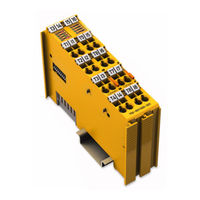
WAGO 750-667/000-003 Manual (150 pages)
4FDI/4FDO 24V/2A PROFIsafe V2 iPar, Fail-safe 4/4 channel digital input/output, 24 VDC, 2 A, PROFIsafe V2.0 iPar
Brand:
WAGO
| Category:
Control Unit
| Size: 5.21 MB
Table of Contents
Table of Contents
3
Notes about this Documentation
7
Validity of this Documentation
7
Copyright
7
Symbols
8
Number Notation
9
Font Conventions
9
Table 1: Number Notation
9
Table 2: Font Conventions
9
Important Notes
10
Legal Bases
10
Subject to Changes
10
Personnel Qualifications
10
Use of the 750 Series in Compliance with Underlying Provisions
10
Technical Condition of Specified Devices
11
Safety Advice (Precautions)
12
Profisafe
15
Figure 1: Mixed Operation of Safety-Related and Non-Safety-Related I/O
15
Figure 2: Profisafe Layer Model
16
Individual Parameters
17
Figure 3: Ipar Server
17
Table 3: Legend for the Ipar Server Figure
18
Device Description
19
View
21
Figure 4: View
21
Table 4: Legend for Figure "View
21
Connectors
22
Data Contacts/Local Bus
22
Figure 5: Data Contacts
22
Power Jumper Contacts/Field Supply
23
Figure 6: Power Jumper Contacts
23
Table 5: Legend for Figure "Power Jumper Contacts
23
CAGE CLAMP ® Connectors
25
Figure 7: CAGE CLAMP ® Connectors
25
Table 6: Legend for Figure "CAGE CLAMP ® Connectors
25
Display Elements
26
Figure 8: Display Elements, Inputs 1
26
Table 7: Legend for Figure "Display Elements, Inputs 1
26
Figure 9: Display Elements, Outputs 1
27
Table 8: Legend for Figure "Display Elements, Outputs 1
27
Figure 10: Display Elements, Communication/ I/O Module Status
28
Table 9: Legend for Figure "Display Elements, Communication / I/O Module
28
Operating Elements
30
Figure 11: Coding Switch for the Profisafe Address (Set to 1018)
30
Schematic Diagrams
31
Input Block Diagram
31
Figure 12: Schematic Diagram
31
Figure 13: Input Block Diagram
31
Output Block Diagram
32
Figure 14: Output Block Diagram
32
Technical Data
33
Device Data
33
Power Supply
33
Table 10: Technical Data - Device
33
Table 11: Technical Data - Power Supply
33
Communication
34
Table 12: Technical Data - Communication
34
Digital Inputs
35
Digital Clock Outputs
35
Table 13: Technical Data - Digital Inputs
35
Table 14: Technical Data - Digital Clock Outputs
35
Digital Power Outputs
36
Table 15: Technical Data - Clock Pulse Duration at Input Filter Time
36
Table 16: Technical Data - Digital Power Outputs
36
Safety Parameters
38
Two-Channel Safety Application, Proof Test Interval 10 Years
38
Table 17: Safety Parameters for 2-Channel Safety Applications - 10 Years
38
Two-Channel Safety Application, Proof Test Interval 20 Years
39
Table 18: Safety Parameters for 2-Channel Safety Applications - 20 Years
39
Single-Channel Safety Application, Proof Test Interval 10 Years
40
Table 19: Safety Parameters for Single-Channel Safety Application
40
Single-Channel Safety Application, Proof Test Interval 20 Years
41
Table 20: Safety Parameters for Single-Channel Safety Application
41
Connection Type
42
Climatic Environmental Conditions
42
Table 21: Technical Data - Field Wiring
42
Table 22: Technical Data - Power Jumper Contacts
42
Table 23: Technical Data - Data Contacts
42
Table 24: Technical Data - Climatic Environmental Conditions
42
Response Times
43
Safe Response Time of Digital Inputs in the Event of a Failure
43
Table 25: Safe Response Time of the Digital Inputs in the Event of Failure
44
Typical Response Time of the Digital Inputs in an Error-Free Case
45
Table 26: Safe Response Time of the Digital Inputs in the Error-Free
45
Safe Response Time of Digital Power Outputs
46
Response Time of the Digital Power Outputs for a Load between Ox+ and Ox− in the Event of Failure
47
Figure 15: Load between Ox+ and Ox
47
Table 27: Response Time of the Digital Power Outputs for a Load between Ox+ and Ox− in the Event of Failure
47
Response Time of the Digital Power Outputs for a Load between Ox+ and 0 V in the Event of Failure
48
Figure 16: Load Bbtween Ox+ and 0 V
48
Table 28: Response Time of the Digital Power Outputs for a Load between Ox+ and 0 V in the Event of Failure
48
Response Time of the Digital Power Outputs for a Load between 24 V and Ox
49
Figure 17: Load between 24 V and Ox
49
Table 29: Response Time of the Digital Power Outputs for a Load between
49
Response Time of the Digital Power Outputs for a Load between Ox+ and 0 V, as Well as 24 V and Ox
50
Figure 18: Load between Ox+ and 0 V, as Well as 24 V and Ox
50
Table 30: Response Time of the Digital Power Output for a Load between Ox+ and 0 V, as Well as 24 V and Ox
50
Approvals
51
Standards and Guidelines
53
Transport and Storage Conditions
54
Process Image
55
Profisafe V1 Mode
55
Table 31: Process Image Profisafe V1 Mode
55
Table 32: Profisafe Inputs, V1 Mode
55
Table 33: Profisafe Outputs, V1 Mode
55
Profisafe V2 Mode
56
Table 34: Process Image Profisafe V2 Mode
56
Table 35: Profisafe Inputs, V2 Mode
56
Table 36: Profisafe Outputs, V2 Mode
56
Mounting
57
Mounting Sequence
57
Inserting and Removing Devices
58
Figure 19: Insert I/O Module (Example)
58
Figure 20: Snap the I/O Module into Place (Example)
58
Inserting the I/O Module
58
Figure 21: Removing the I/O Module (Example)
59
Removing the I/O Module
59
Connect Devices
60
Connecting a Conductor to the CAGE CLAMP
60
Figure 22: Connecting a Conductor to a CAGE CLAMP
60
Power Supply Concept
61
Figure 23: Infeed for F I/O Modules 750-66X and 753-66X
62
Figure 24: Infeed for Profisafe I/O Modules 75X-66X with Backup
63
Using a Backup Capaciter in Case of Interruptions in the Power Supply
63
Using 230 VAC I/O Modules
64
VAC I/O Modules and F I/O Modules Are Used Together in One Fieldbus Node
64
VAC Modules Are Used in Another Fieldbus Node that Contains no F I/O Modules
64
Connection Examples
65
Connection Examples for Digital Inputs in the "Standard" Operating Mode
65
Emergency off Connection, Single-Channel
65
Figure 25: Connection 4 X Emergency-Off, Single-Channel, Short-Circuit
66
Figure 26: Connection 4 X Emergency-Off, Single-Channel, Short-Circuit
66
Emergency off Connection, Dual Channel, Equivalent Evaluation
67
Figure 27: Connection 2 X Emergency-Off Switch, Dual Channel, Equivalent
68
Figure 28: Connection 1 X Interlock Monitoring, Dual Channel, Antivalent
69
Protective Door Monitoring Connection, Dual Channel, Antivalent Evaluation
69
Connection Example for Digital Inputs in Rotary Table Operating Mode (1 of N)
70
Figure 29: Connection 1 X Mode Selector Switch
70
Connection Examples for Digital Power Outputs
71
Switching Grounded Loads
71
Switching Inductive Loads
72
7.3.3.2.1 Selecting an External Diode Recovery Circuit
72
Connecting a Load between Ox+ and Ox
74
Switching Electronic Loads
74
Connecting Loads from Ox+ and Ox− to 0 V and 24 V
75
Figure 30: Connecting Loads from Ox+ and Ox- to 0 V and 24 V
75
Connecting Two Parallel Loads to a Digital Power Output
76
Figure 31: Connecting Two Parallel Loads to a Digital Power Output
76
Connecting Loads between Ox+ to the Ground Connection 0 V
77
Figure 32: Connecting Loads from Ox+ to Ground Connection 0 V
77
Connecting the Digital Power Outputs to Digital Inputs
78
Figure 33: 4 X Motor Connection, Single-Channel with Feedback
79
Motor Connection, Single-Channel with Feedback (1 Contactor Per Motor)
79
Connecting 2 Motors, Two-Channel with Feedback (2 Actors Per Motor)
80
Figure 34: 2 X Motor Connection, Two-Channel with Feedback
80
Connecting 4 DC Motors
82
Figure 35: 4 X DC Motor Connection
82
Commissioning
83
Startup and Maintenance Instructions
83
Figure 36: Example of a Serial Number
83
Proof Test Interval/Usage Duration
83
Adding or Replacing Components
84
Setting the Profisafe Address
84
Setting the Profisafe Address Using the Coding Switch
84
Setting the Profisafe Address Using the WAGO Parameterization Tool
85
Parameteriziation of the F I/O Module with the WAGO Parameterization Tool
85
ONLINE Mode
86
OFFLINE Mode
88
Description of the Call Options
90
Direct Start from the Operating System
90
Indirect Start Via WAGO-I/O-CHECK from the Operating System
90
Direct Start from the Configuration Program (Device Level TCI Conformance Class 3)
91
Direct Start from the Configuration Program (Module Level TCI Conformance Class 3)
91
Indirect Start Via WAGO-I/O-CHECK from the Configuration Program (Device Level TCI Conformance Class 2)
91
Indirect Start Via WAGO-I/O-CHECK from the Configuration Program (Module Level TCI Conformance Class 2)
91
Conformance Class 3 OFFLINE
92
Direct Start from the Configuration Program
92
Direct Start from the Configuration Program (Device Level TCI Conformance Class 3 OFFLINE)
92
Adjustable Parameters
93
Table 37: Adjustable Parameters
93
Parameter Input Filter Time
94
Table 38: Input Pulse Durations Depending on the Input Filter Time
94
Parameter Short-Circuit Test IX
95
Table 39: Input /Clock Output Assignment
95
Table 40: Error Detection
96
Parameter Two-Channel Analysis IX & IX+1
97
Discrepancy Time IX & IX+1 Parameter
98
Parameter Valence Evaluation IX & IX+1
100
Table 41: Antivalent Evaluation
100
Parameter Restart Inhibit IX & IX+1
101
Table 42: Equivalent Evaluation
101
Operating Mode Parameter
102
Table 43: Necessary Signal States for Acknowledgement if the Restart Inhibit Is Set to "Yes
102
Parameter Open Load Detection
103
Test Pulse Duration Parameter
104
Programming the Safe PLC
106
F I/O Module with Ipar Functionality and Ipar Server
107
F I/O Module Without Ipar Functionality
107
F I/O Module with Ipar Functionality Without Ipar Server
108
Diagnostics
110
Behavior in the Event of an Error
110
Diagnosis of Errors
111
Table 44: Diagnostic Messages
112
Acknowledging Error Messages
118
Variant 1: User Acknowledgement Via "Oa_Req
119
Figure 37: Schematic Representation for User Acknowledgement Via
119
Variant 2: User Acknowledgement Via "Oa_Req" and "F_Ack
120
Figure 38: Schematic Representation for User Acknowledgement Via "Oa_Req" and "F_Ack
120
Service
121
Replacing an F I/O Module
121
Procedure
121
I/O Module with Ipar Server Functionality
122
Profisafe Address Set Using the Coding Switch
122
Profisafe Address Set Using the Parameterization Tool
122
I/O Module Without Ipar Server Functionality
122
Profisafe Address Set Using the Parameterization Tool
123
Use in Hazardous Environments
124
Marking Configuration Examples
125
Marking for Europe According to ATEX and Iecex
125
Figure 39: Marking Example According to ATEX and Iecex
125
Figure 40: Text Detail - Marking Example According to ATEX and Iecex
125
Table 45: Description of Marking Example According to ATEX and Iecex
126
Figure 41: Marking Example for Approved Ex I I/O Module According to
127
Figure 42: Text Detail - Marking Example for Approved Ex I I/O Module According to ATEX and Iecex
127
Table 46: Description of Marking Example for Approved Ex I I/O Module According to ATEX and Iecex
128
Table 48: Description of Marking Example for Approved Ex I I/O Module
128
Marking for the United States of America (NEC) and Canada (CEC)
129
Figure 43: Marking Example According to NEC
129
Figure 44: Text Detail - Marking Example According to NEC 500
129
Table 47: Description of Marking Example According to NEC 500
129
Figure 45: Text Detail - Marking Example for Approved Ex I I/O Module
130
Figure 46: Text Detail - Marking Example for Approved Ex I I/O Module
130
Table 49: Description of Marking Example for Approved Ex I I/O Modules
130
Figure 47: Text Detail - Marking Example for Approved Ex I I/O Modules
131
Table 50: Description of Marking Example for Approved Ex I I/O Modules
131
Installation Regulations
132
Special Notes Regarding Explosion Protection
132
Special Notes Regarding ANSI/ISA Ex
134
Appendix
135
Overview of Profisafe F Parameters
135
Table 51: Profisafe F Parameters
135
Profisafe Certificates
138
Glossary
139
List of Figures
146
List of Tables
148
Advertisement
Advertisement
Related Products
WAGO I/O-SYSTEM 750-666/000-003
WAGO 750-668/000-004
WAGO WAGO-I/O-SYSTEM 750-628
WAGO 750-637
WAGO 750-645
WAGO 750-606
WAGO 750-651/000-001
WAGO 750-651/000-002
WAGO 750-652/040-000
WAGO 750-651/000-003
WAGO Categories
I/O Systems
Control Unit
Power Supply
Switch
Controller
More WAGO Manuals
Login
Sign In
OR
Sign in with Facebook
Sign in with Google
Upload manual
Upload from disk
Upload from URL