
Related Manuals for Rievtech xLogic ELC Series


Summary of Contents for Rievtech xLogic ELC Series
- Page 1 Programmable Relay User's Manual Applied to ELC&PR series Ver: 3.0 Rievtech Electronic Co.,Ltd...
- Page 2 Contents Introduction Getting started Installation and wiring Programming xLogic Configuring &software Applications Technical data ...
- Page 3 Data adjustments can easily be performed via the keypad, the LCD display, or through the Rievtech-to-use xLogic soft. DIN-rail and panel-mounted options are both available, offering full flexibility to the various installation needs of your application.
- Page 4 Please read the complete operating instructions before installation and commissioning. Rievtech does not accept any liability for possible damage to persons, buildings or machines, which occur due to incorrect use or from not following the details.
- Page 5 Trademarks All names identified by xLogic are registered trademarks of the Rievtech. The remaining trademarks in this publication may be trademarks whose use by third parties for their own purposes could violate the rights of the owner.
-
Page 6: Table Of Contents
Contents Contents ......................................6 Chapter 1 General Introduction to xLogic ........................11 1.1 Overview ....................................11 1.2 Highlight feature ................................11 Chapter 2 Hardware models and resources ........................16 2.1 Naming Rules of ELC&PR Series ..........................16 2.2 Hardware model selection .............................. 17 2.3 Structure &... - Page 7 5.3.3 NAND ..................................69 5.3.4 NAND with edge evaluation ..........................70 5.3.5 OR ....................................71 5.3.6 NOR ..................................... 72 5.3.7 XOR ..................................... 72 5.3.8 NOT ....................................73 5.3.9 Boolean Function ..............................74 5.4 Basics on special functions ............................. 75 5.4.1 Designation of the inputs ............................ 75 5.4.2 Time response .................................
- Page 8 5.5.29 Analog Ramp ..............................145 5.5.30 Analog Math ................................ 147 5.5.31 Analog math error detection ........................149 5.5.32 Modbus Read ..............................151 5.5.33 Modbus Write ..............................157 5.5.34 Modbus read write ............................161 5.5.35 Data latching relay ............................167 5.5.36 PI controller ................................. 169 5.5.37 Memory write ..............................
- Page 9 5.8.2 Toolbar ..................................228 5.8.3 Programming Toolbar ............................229 5.8.4 Simulation Tool and status window ......................230 5.9 Basic Operation ................................233 5.9.1 Open File ................................. 233 5.9.1.1 Open New File ............................233 5.9.1.2 Open Existed Document ........................235 5.9.2 Edit Function Diagram Program ........................236 5.9.2.1 Place Function Block ..........................
- Page 10 7.3.1 Standard solution ..............................342 7.3.2 The scheme of xLogic ............................343 7.4 Factory door ..................................345 7.4.1 Standard solution ..............................345 7.4.2 The scheme of xLogic ............................346 7.5 Daylight lamp system ..............................348 7.5.1 Standard solution ..............................349 7.5.2 The scheme of xLogic ............................
-
Page 11: Chapter 1 General Introduction To Xlogic
Chapter 1 General Introduction to xLogic 1.1 Overview xLogic is a universal logic module made by Rievtech. xLogic , a compact, expandable CPU that can replace mini PLC, multiple timers, relays and counters, Splitting the difference between a timing relay and a low-end PLC, Each CPU has a real-time clock and calendar, and supports optional expansion I/O modules to enhance your control and monitoring applications . - Page 12 Standard Modbus RTU/ASCII/TCP communication protocol supported. It’s optional for xLogic to act as slave or master in certain Modbus communication network. (easy connect to other factory touch screen by RS232 cable, RS485 module) CAN BUS protocol based expansion modules(PR-18/PR-24 series CPU) ...
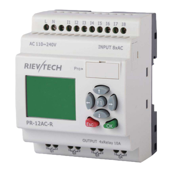
- Page 13 *Classes2: AC110-240V: i.e.: PR-6AC Series, PR-12AC series, PR-18AC series , PR-24AC series. In the versions: * With Display: with “-HMI” model, such as PR-12DC-DA-R-HMI * Without Display: PR-6 series and with “-CAP” model, such as PR-12DC-DA-R-CAP. Only PR-12 has -CAP version.
- Page 14 xLogic offers different ways to communicate within the system. RS485 port The RS485 port is used for communication between the CPU and various devices or equipments which have the standard RS485 port. Communicate using Modbus RTU/ASCII protocol. Note:PR-RS485 module is required to connect the CPU to RS485 BUS. RS232 or USB port (ELC-ES232/ ELC-USB needed) If there is no network required and only one main module with some expansion modules is needed for the application, the down- and upload of the project to and from the main module happens over the standard...
- Page 15 Note xLogic CPU may be equipped with expansion modules of the different voltage class, but expansion module must be supplied the correct power corresponding to its type. Each xLogic CPU provides the following connections for the creation of the circuit program, regardless of the number of connected blocks: Digital inputs I1 to I4(PR-6), I1 to I8(PR-12), I1 to IC (ELC-18)...
-
Page 16: Chapter 2 Hardware Models And Resources
Chapter 2 Hardware models and resources 2.1 Naming Rules of ELC&PR Series 1.Series name: ELC series; PR series. 2.Points of input and output 3.Supply power AC or DC 4.Digital/Analog D: digital DA: digital/analog 5.Output type R: relay T: transistor TN = “PNP” transistor; TP= “NPN” transistor 6. -
Page 17: Hardware Model Selection
5.Digital/Analog D: digital DA: digital/analog 6.Output type R: relay TP: “NPN” transistor;TN :“PNP” transistor 2.2 Hardware model selection PR-6 Series CPU Units (None expandable) High-speed Model Expansion Supply voltage Inputs Outputs count AC110~AC240V/ PR-6AC-R 4 digital 2 relays (10A) DC110-DC240V PR-6DC-DA-R DC12-24V 4 digital/4(0...10V) - Page 18 PR-24AC-R-HMI AC110~AC240V 16 digital 10 relays (10A) 6(0...10V)/6digital PR-24DC-DA-R-HMI DC12-24V 10 relays (10A) 4(I9-IC)(60KHZ) +8 digital 2(0/4...20mA)+ relays(10A)+2Transistor(0.3 PR-24DC-DAI-RTA DC12-24V 4(0...10V)/4digital 4(I9-IC)(60KHZ) YES(10khz) A/PNP)+1(0...10V)/(0...20m +8 digital Expansion Modules(For PR-18,PR-24 series) Model Supply voltage Inputs Outputs PR-E-16AC-R AC110~ 8 digital 4 relays(10A)+4 relays(3A) AC240V 4 relays(10A)+4 relays(3A) PR-E-16DC-DA-R...
-
Page 19: Structure & Dimension
2.3 Structure & dimension 1. PR-6 Series CPU&EXM-E Series Extension 1.Power supply 2. Input 3. Program port for applied to ELC-6 CPU 4.Output 2. Standard PR-12 series with LCD model: 1.Power supply&Input terminals 2. Program Port(can be used as RS232 port with ELC-RS232 or RS485 port with PRO-RS485) 3.HMI/LCD panel 4.keypad 5.Output terminals 3. - Page 20 1.Power supply&Input terminals 2. Program Port(can be used as RS232 port with ELC-RS232 or RS485 port with PRO-RS485) 3.RUN/STOP Indicator 4.Output terminals 4. PR-14 and PR-18 series model: 1.Power supply&Input terminals 2.HMI/LCD panel 3.keypad 4.Output terminals 5. Program Port(can be used as RS232 port with ELC-RS232 or RS485 port with PRO-RS485) 6.Extension port Dimensions of PR-14 and PR-18:...
- Page 21 PR-24 series CPU 1. Power supply 2.Input 3. Program/RS232 port 4.HMI/LCD panel 5.keypad 6.Extension/RS485 port 7.Output 6. ELC-22 Ethernet CPU...
- Page 22 1.Power supply 2.Input 3. Program/RS232 port 4.HMI/LCD panel 5.keypad 6.Extension/RS485 port 7.Output 8.LAN port 11. PR-E extension module: 1. Power supply&Input terminals 2. Connection cable between CPU and extension(Detached) 3.Extension port(left) 4. RUN/STOP indicator 5. Extension port( Right) 6. Output terminals Dimensions of PR-E:...
-
Page 23: Chapter 3 Installing/Removing Xlogic
Dimensions of ELC-12-N Ethernet CPU: Chapter 3 Installing/removing xLogic Dimensions The xLogic installation dimensions are compliant with DIN 43880. xLogic can be snap-mounted to 35 mm DIN rails to EN 50022 or on the wall. xLogic width: EXM-E expansion module and PR-6 series CPU have a width of 48mm ... -
Page 24: Din Rail Mounting
Note The figure below shows you an example of the installation and removal of an PR-18 CPU and one expansion module of PR-18 CPU. W a r n i n g Always switch off power before you “remove” and “insert” an expansion module. 3.1 DIN rail mounting Mounting How to mount a xLogic module and an expansion module onto a DIN rail:... -
Page 25: Wall-Mounting
Note:If you need install the expansion and CPU on different rows, you need order the longer flat connection which is used to connected with CPU, the longest distance can be 200meters between the CPU and the end expansion module. Removal To remove xLogic: .. - Page 26 Drilling template for wall-mounting Before you can wall-mount xLogic, you need to drill holes using the template shown below. All dimensions in mm Bore hole for Ø M4 screw, tightening torque 0.8 to 1.2 Nm 1. xLogic CPU PR-6 series: PR-12 Series CPU...
- Page 27 PR-14 and PR-18 series: 1.PR-18 CPU;2. PR-E extension PR-24 series...
-
Page 28: Wiring Xlogic
ELC-12-N series(applied to CPU and extensions): 3.3 wiring xLogic Wire the xLogic using a screwdriver with a 3-mm blade. You do not need wire ferrules for the terminals. You can use conductors with cross-sections of up to the following thicknesses: 1 x 2.5 mm ... -
Page 29: Connecting Xlogic Inputs
Note A power failure may cause an additional edge triggering signal. Data of the last uninterrupted cycle are stored in xLogic To connect xLogic to the power supply: 3.4.2 Connecting xLogic inputs 1. Requirements the inputs you connect sensor elements such as: momentary switches, switches, light barriers, daylight control switches etc. - Page 30 AC Type DC Type <40VAC <5VDC Signal status <0.03mA <0.1mA Input current >79 VAC >10VDC Signal status Typical 0.06 Typical 0.3mA Input current 0.24mA Analogue input AI1-AI4(0-10V DC)(PR-6,PR-12) Note: . For PR-6DC-DA-R, PR-12DC-DA ,PR-14DC-DA, PR-18DC-DA ,PR-24DC-DA Series and versions. That can receive analog input.
- Page 31 AC type digital inputs * Analog Inputs (DC 0…10V) *Analog inputs current Inputs (0…20mA)
- Page 32 The above figure shows how to make a four-wire current measurement. PR-E-PT100 It can be connected with one two-wire or three-wire resistance-type thermocouple. When two-wire technology applied, the terminals “M1+ and IC1” (this rule also shall be applied to” M2+ and IC2”, “M3+ and IC3”...
-
Page 33: Connecting Xlogic Outputs
3.4.3 Connecting xLogic Outputs 1. Requirement for the relay output Various loads such as lamp, fluorescent tube, motor, contact, etc., can be connected to the outputs of xLogic. The maximum ON output current that can be supplied by xLogic is 10A for the resistance load and 3A for the inductive load. - Page 34 PR-E-AQ-VI(DC0..10V analog output). EXM-E-AQ-I /PR-E-AQ-VI PR-RS485 Actually, PR-RS485 is just a converter with photo isolation bringing out 3 wiring terminals(short circuited inner of such 3 terminals, so only one channel RS485 bus is available) from RS485 port (2x8pin) of CPU(PR-18/ELC-22/PR-24) for your easy connection with other devices.
-
Page 35: Communication Port Instructions
If “RT1”, RT2” terminal are short connected, one 120R resistor will be connected between A/+ and B/- 3.4.4 Communication port instructions: PR-6 CPUs PR-14,PR-18 ,ELC-22 and PR-24 CPUs... - Page 36 1. Programming port/RS232 port (ELC-RS232 ,ELC-USB,ELC-Copier,ELC-MEMORY,ELC-BATTERY,PRO-RS485) should be inserted in this port) When the programming port should be used as the standard RS232 port (D-shape 9 pin header) ,the ELC-RS232 cable needed.Blow is show you the pin definition of the header: function others NULL...
- Page 37 3------RS485 A 5------RS485 B 4------GND 6------GND 7------CANL 9------CANH 15------+5V 16------+5V Communication between CPU and expansion module will use 4.7,9,15 pin. PR-RS485 module is required when PR-18/ELC-22/PR-24 CPU communicate with the third party devices via RS485 bus PR-12 CPUs With HMI model Without HMI model 1.
-
Page 38: Chapter 4 Parameters Modification Hmi Operation
Chapter 4 Parameters modification HMI operation 4.1 Overview of xLogic menu PR-12 ,PR-14,PR-18,ELC-22,ELC-26 series CPU has same menu on the LCD, so here we show the PR-18 for example. Parameter assignment mode Parameter assignment menu:... -
Page 39: Lcd Panel Instruction
4.2 LCD panel instruction PR-12 Series CPU PR-18 Series CPU ELC-22 and ELC-26 series CPU 1. Display area: 4x16 characters can be displayed 2. 4 X Function key: operate the program by pressing down these key (Only for ELC-22-N and PR-24 series CPU, invalid for PR-12 and PR-18 series CPU;F1--F4 are all available on ELC-43TS) 3. - Page 41 After being powered on, xLogic shall self-check program stored in the CPU. If the program is accurate, then the CPU will be running, meanwhile the system cover will show as follows: In xLogicsoft, this interface is defaulted as its initialization screen. If there are several parameter pages, users can press key to go to the page you would like.
-
Page 42: Select Function Page
Cursor keys can be controlled in this page by press arrow keys and ESC key at the same time. If xLogic has several alarm interfaces in the same period and it only displays the message with highest priority in the function block, also you may go through all alarm messages by pressing key. - Page 43 Brief introduction on 5 options of function page: Run/stop Select this menu to switch over xLogic status between RUN and Stop. Refer to chapter4.3.1 for details. Set Param To set function block parameter. Refer to chapter 4.3.2 for details. Set…...
-
Page 44: How To Switch Run/Stop
4.3.1 How to switch Run/Stop You should first select FUNCTION PAGE. (Read 4.3) 1. Move the cursor to “Run/stop”: Press “UP” or “DOWN” key. 2. Move the cursor to "Yes": Press OK key. After pressing ESC key, you’ll find out your circuit program has changed to “stop” status as figure below shows: 4.3.2 Set parameter If you want to select a parameter, you need do as the following procedures:... - Page 45 2. Confirm by pressing OK key. Then xLogic displays the first parameter, so you can modify as you like. If there is no parameter to set/modify, you can press ESC key to return. 3. Select parameter you intend to modify. 4.
- Page 46 Confirm the value after modification: press OK key. Note: When xLogic is running, not only time value but also time unit(S,M,H) can be altered , but Besides alter time parameter at RUN time ,you can alter time base(s=second, m=minute ,h=hour). Current value of time T View time T in parameter mode: You are allowed to modify configuration time.
-
Page 47: Set Password
Current value of hour counter In parameter mode, the view of hour counters: You can edit configured time interval (MI). Current value of threshold trigger In parameter mode, the view of threshold trigger: You can alter the threshold value of switching on /off. 4.3.3 Set password xLogic supply password protection function for your program. - Page 48 A password contains less than or equal to 4 characters and each character is Arabian number from 0 to 9 .It is easy to specify, edit or remove the password directly on the xLogic in the “Password” menu of the function page: You should first select the FUNCTION PAGE.
- Page 49 Modify password: In order to modify password, you are required to present current password. In the menu of the FUNCTION PAGE: 1. Move the cursor to “Password”: Press “UP” or “DOWN” key. 2. Confirm “Password”: Press OK key. Select “Old” and input primary password (in our instance is “1234”), the process is the same as the step 3 to step 10 mentioned above.
- Page 50 How to remove the password: In case you need to remove password .e.g. allow the other users to edit your program, then you must know the current password. The process of removing password is the same as that of modifying password.
-
Page 51: How To Set Address Of Cpu And Expansion Module
The menu File->Properties (Parameter) There are 2 password settings can be applied to the program, one is the program password, one is parameter password. Program password: If you set the program password, then the password is required when you want to upload the program into PC. - Page 52 Confirm with "OK" Change the address with arrow keys, and confirm with "Ok". The CPU address also can be set by xlogicsoft, if the CPU without HMI, you only can set the expansion address with such method. You can set the CPU address by the menu Tools-> transfer-> set PLC’s address in xlogicsoft. Part 2 :Set address of PR-E extensions.(PR-E-16DC-DA-R etc..)
- Page 53 1. Plastic slice Step 1: Using a screwdriver , take the plastic slice down and we’ll find a dial switch. 2: Dial the switch as the below instructions to set the address what you need. Up to 8 extensions (includes IO ,AQ,AI,PT100 modules) can be connected with the CPU . The default address of PR-E extensions is 1 and the dial switch as below: Address 1: means the switch position...
-
Page 54: Set Lcd (Backlight And Contrast)
Address 8: Notes: 1.The address setup of the extension module must be before powering on. Modification when powering on will be ineffective. 2.Freely connection with CPU and expansion , do not care the power supply type of CPU and extensions ,that means the AC type module also can be connected with the DC type module or AC type expansion module also can be connected with DC type CPU. - Page 55 3.Select "Backlight"menu and click "OK" 4. Default is 10 seconds, and another option is "Always On". Confirm with "OK" Modify the contrast Confirm with "OK"...
-
Page 56: Set Communication Parameters
Modify the contrast with Left or right key, and confirm with "Ok". 4.3.6 Set communication parameters Select "Set Com" menu from the menu "Set..". Confirm with "Ok" COM0: RS232 port or programming port. COM1: RS485 port(For the PR-RS485 module which shall be connected to PR-14,PR-18,PR-24,ELC-18,ELC-22,ELC-26 CPU) COM2: Built-in RS485 port for PR-14 and PR-24CPU. - Page 57 Confirm with "OK" Change it with pressing Up and Down key And confirm with "OK" Set Modbus protocol Confirm with "OK"...
-
Page 58: Modification Of System Time
Change with Up and Down key. And confirm with "OK" There are 4 options available: RTU, ASCII, TCP RTU, TCP ASCII. Note:If you want to use the Modbus TCP protocol, generally, you can select the "TCP RTU". 4.3.7 Modification of System Time You should first select the FUNCTION PAGE. - Page 59 Press “UP” or “DOWN” key to realize the date which you want to set .After you finished your setting, press OK key to return to: If you want to set the time further, please move the cursor to” Set Time” menu, then press OK key: Here you can set week day (From Monday to Sunday) and the clock.
-
Page 60: Chapter 5 Configuring & Programming Software
Generating and printing of an overview chart for the circuit program Saving a backup of the circuit program on the hard drive or other media Rievtech configuration of blocks Transferring the circuit program – from the xLogic to the PC and –... -
Page 61: Xlogic Functions
key. 5.1 xLogic Functions PR series adapts programming methods by means of function blocks. A total of 9 general function blocks, 60 special function blocks, and 11 input & output function blocks are configured. And each block can achieve a specific control function independently, e.g. TOND, TOFD, SBPL, TBPL, SCHD, etc. As several blocks are linked up in a specific way, relatively complicated control functions can be performed. -
Page 62: Cursor Keys
I85 means the I5 input of the expansion with address 8. 5.2.2 Cursor keys Fashion: Classic: Up to four cursor keys are available to you. Cursor keys are programmed for the circuit program in the same ways as other inputs. Cursor keys can save switches and inputs, and allow operator control of the circuit program. -
Page 63: Permanent Logical Levels Hi And Lo
5.2.4 Permanent logical levels HI and LO Fashion: Classic: Set the block input to logical hi (hi = high) to set it permanently to logical '1' or 'H' state. Fashion: Classic: Set the block input to logical lo (lo = low) to set it permanently to logical '0' or 'L' state. 5.2.5 Panel Key Fashion: Classic:... -
Page 64: Shift Register Bits
5.2.6 Shift register bits Fashion: Classic: xLogic provides the shift register bits S1 to S8, which are assigned the read-only attribute in the circuit program. The content of shift register bits can only be modified by means of the Shift register special function 5.2.7 Analog inputs Fashion:... -
Page 65: F (Digital Flag)
5.2.8 F (digital flag) Fashion: Classic: Flags are used when xLogic works in a communication system. F is digital flag which is used to save /transfer signal 1 or 0(data format is Bit) and AF is analog flag which is used to save /transfer analog values (data format is Signed short) between the master and slave devices. -
Page 66: Af (Analog Flag)
5.2.9 AF (Analog flag) Fashion: Classic: Flags are used when xLogic works in a communication system. AF is analog flag which is used to save /transfer analog values (data format is Signed short) between the master and slave devices. Up to 32(PR-6) and 256(PR-12/PR-18/PR-24) for xLogic CPU can be used when programming. -
Page 67: And
AND with edge evaluation NAND (Not AND) NAND with edge evaluation (Not OR) (exclusive OR) (negation, inverter) BOOLEAN FUNCTION BOOLEAN FUNCTION 5.3.1 AND Fashion: Classic: (Symbol in xLogic) The output of an AND function is only 1 if all inputs are 1, i.e. when they are closed. A block input that is not used (x) is assigned: x = 1. -
Page 68: And With Edge Evaluation
Input1 Input2 Input 3 Input 4 Output 5.3.2 AND with edge evaluation Fashion: Classic: (Symbol in xLogic) The output of an AND with edge evaluation is only 1 if all inputs are 1 and at least one input was 0 during the last cycle. -
Page 69: Nand
5.3.3 NAND (Symbol in xLogic) Fashion: Classic: The output of an NAND function is only 0 if all inputs are 1, i.e. when they are closed. A block input that is not used (x) is assigned: x = 1. Logic table of the NAND block: Input 1 Input 2 Input 3... -
Page 70: Nand With Edge Evaluation
5.3.4 NAND with edge evaluation Fashion: Classic: The output of a NAND with edge evaluation is only 1 at least one input is 0 and all inputs were 1 during the last cycle. The output is set to 1 for the duration of one cycle and must be reset to 0 at least for the duration of the next cycle before it can be set to 1 again. - Page 71 5.3.5 OR Fashion: Classic: (Symbol in xLogic) The output of an OR is 1 if at least one input is 1 (closed). A block input that is not used (x) is assigned: x = 0. Logic table of the OR function: Input 1 Input 2 Input 3...
-
Page 72: Nor
5.3.6 NOR (Symbol in xLogic) Fashion: Classic: The output of a NOR (NOT OR) is only 1 if all inputs are 0 , i.e. when they are open. When one of the inputs is switched on (logical 1 state), the output is switched off. A block input that is not used (x) is assigned: x = 0. -
Page 73: Not
(Symbol in xLogic) Fashion: Classic: The XOR (exclusive OR) output is 1 if the signal status of the inputs is different. A block input that is not used (x) is assigned: x = 0. Logic table of the XOR function: Input 1 Input 2 Output... -
Page 74: Boolean Function
5.3.9 Boolean Function Fashion: Classic: The BOOLEAN function gives the value of the output according to the combination of inputs. The function has four inputs, and therefore 16 combinations. These combinations can be found in a truth table; for each of these, the output value can be adjusted. The number of configurable combinations depends on the number of inputs connected to the function. -
Page 75: Basics On Special Functions
5.4 Basics on special functions Because of their different input designation, you can see right away that there is a difference between the special functions and basic functions. SFs contain timer functions, retentive functions and various parameter assignment options, which allow you to adapt the circuit program to suit your own requirements. -
Page 76: Time Response
This input will not be connected. Here, you configure the time patterns. P (Priority): This is an open input. Here, you define priorities and specify whether a message is to be acknowledged in RUN. 5.4.2 Time response Parameter T In some of the SFs it is possible to configure a time value T. When you preset this time, note that your input values are based on the time base set: Time base _ _ :... -
Page 77: Retentivity
Because the internal real-time clock of an xLogic is backed up, it continues operation after a power failure. The ambient temperature influences the backup time. At an ambient temperature of 25°C, the typical backup time of xLogic is 100 hours. 6.4.4 Retentivity The switching states and counter values of SFs can be set retentive. - Page 78 Gain –10.00 +10.00 Offset –10000 +10000 Mathematical rule Actual value Ax = (internal value at input Ax∙gain) + offset Gain and offset calculation The gain and offset is calculated based on the relevant high and low values of the function. Example 1: The available thermocouples have the following technical data: –30 to +70℃, 0 to 10 V DC (i.e.
-
Page 79: Special Functions List - Sf
5000 1000 10000 0.01 0.01 1000 0.01 1000 1000 1500 –200 –200 –200 1000 –200 –10000 –10000 1000 –10000 0.02 0.01 0.02 0.02 0.02 5.5 Special functions list – SF When you create your circuit program in xLogicsoft, you find the special function blocks in the SF list. You can invert the inputs of SFs individually, i.e. - Page 80 Edge triggered wiping relay Asynchronous pulse generator Random generator Stairway lighting switch Multiple function switch Weekly timer Yearly timer Counter Up/down counter Hours counter Threshold trigger Analog Analog threshold trigger Analog differential trigger Analog comparator Analog value monitoring Analog amplifier Analog multiplexer Pulse Width Modulator(PWM) Analog math...
- Page 81 Analog math error detection Miscellaneous Latching relay Pulse relay Message texts Softkey Shift register Data latching relay Modbus Read Modbus Write Memory Write Memory Read Word to bit Bit to word Device Reset Comport status...
- Page 82 RH math Cam control block Angular Cam Timer Pumps management Defrost Comparison of 2 values Multicompare Compare in Zone Conversion word bits Conversion bits word Demultiplexer Multiplexing...
-
Page 83: On-Delay
Multiplexer Square root Sin Cos 5.5.1 On-delay Fashion: Classic: Short description The output is not switched on until a configured delay time has expired. Connection Description Trg input The on delay time is triggered via the Trg (Trigger) input Parameter T represents the on delay time after which the output is switched on (output signal transition 0 to 1). - Page 84 to chapter 5.2.2 please. For information on the validity and accuracy of the time base, refer to the xLogic time-base list as follows: Valid ranges of the time-base, if T = parameter Time-base Max. Min. resolution Accuracy value s (seconds) 99:99 10 ms ±...
-
Page 85: Off-Delay
5.5.2 Off-delay Fashion: Classic: Short description The output with off delay is not reset until a defined time has expired. Connection Description Input Trg Start the off delay time with a negative edge (1 to 0 transition) at input Trg (Trigger) Input R Reset the off delay time and set the output to 0 via the R (Reset) input. -
Page 86: On-/Off-Delay
Description of the function Output Q is set to 1 momentarily with a 0 to 1 transition at input Trg. At the 1 to 0 transition at input Trg, xLogic retriggers the current time T, and the output remains set. The output Q is reset to 0 when T reaches the value specified in T (T =T) (off delay). -
Page 87: Retentive On-Delay
Analog multiplexer: AQ Analog ramp: AQ Analog math: AQ PI controller: AQ Data latching relay: AQ Up/Down counter: Cnt The value of "TH","TL"can be set/modified in parameter mode. For information about how to modify, refer to chapter 7.2.2 please. For information on the validity and accuracy of the time base, refer to 7.4.2 Timing diagram Description of the function The time T... - Page 88 A one-shot at the input triggers a configurable time. The output is set upon expiration of this time. Connection Description Input Trg Trigger the on delay time via the Trg (Trigger) input. Input R Reset the time on delay time and reset the output to 0 via input R (Reset).
-
Page 89: Wiping Relay (Pulse Output)
5.5.5 Wiping relay (pulse output) Fashion: Classic: Short description An input signal generates an output signal of a configurable length. Connection Description Input Trg You trigger the time for the wiping relay with a signal at input Trg (Trigger) TL represents the time after which the output is reset Parameter (output signal transition 1 to 0). -
Page 90: Edge Triggered Wiping Relay
remains set. When Ta reaches the value defined at T (Ta=T), the output Q is reset to 0 state (pulse output). If the signal at input Trg changes from 1 to 0 before this time has expired, the output is immediately reset from 1 to 0. -
Page 91: Asynchronous Pulse Generator
The value of "TH","TL"can be set/modified in parameter mode. For information about how to modify, refer to chapter 5.2.2 please. Timing diagram = 0; N = 1 Description of the function With the change at input Trg to 1, the time T (time low) is triggered. -
Page 92: Random Generator
Parameter The pulse width TH and the inter-pulse width TL can be provided by the actual value of another already-programmed function: Analog comparator: Ax – Ay Analog trigger: Ax Analog amplifier: Ax Analog multiplexer: AQ Analog ramp: AQ Analog math: AQ PI controller: AQ Data latching relay: AQ Up/Down counter: Cnt... - Page 93 Input En The positive edge (0 to 1 transition) at the enable input En (Enable) triggers the on delay for the random generator. The negative edge (1 to 0 transition) triggers the off delay for the random generator. Parameter The on delay is determined at random and lies between 0 s and T The off delay is determined at random and lies between 0 s and T...
-
Page 94: Stairway Lighting Switch
When input En is reset 0, a random time (off delay time) between 0 s and T is set and triggered. If the status at input En is 0 at least for the duration of the off delay time, the output Q is reset to 0 when the off delay time has expired. - Page 95 to chapter 5.2.2 please. Timing diagram Changing the time base You can change the pre-warning time base and the period. Time base Pre-warning time Pre-warning period Seconds 750 ms 50 ms Minutes 15 s Hours 15 min 1 min * makes sense only for programs with a cycle time of < 25 ms Description of the function Output Q is set to 1 with a 0 to 1 signal transition at input Trg.
-
Page 96: Multiple Function Switch
5.5.10 Multiple function switch Fashion: Classic: Short description Switch with two different functions: Pulse switch with off delay Switch (continuous light) Connection Description Input Trg With a signal at input Trg (Trigger) you set output Q (continuous light), or reset Q with off delay. Output Q can be reset with a signal at the Trg input. -
Page 97: Weekly Timer
Analog trigger: Ax Analog amplifier: Ax Analog multiplexer: AQ Analog ramp: AQ Analog math: AQ PI controller: AQ Data latching relay: AQ Up/Down counter: Cnt The value of "T","TL"can be set/modified in parameter mode. For information about how to modify, refer to chapter 5.2.2 please. Timing diagram Description of the function Output Q is set to 1 with a 0 to 1 signal transition at Trg. - Page 98 Short description The output is controlled by means of a configurable on/off date. The function supports any combination of weekdays. Connection Description Parameter At the No1, No2, No3 (cam) parameters you set the on and off triggers for each cam of the weekly timer.
- Page 99 Days of the week The prefix "D=" (Day) has the following meaning: ● M: Monday ● T: Tuesday ● W: Wednesday ● T: Thursday ● F: Friday On-/Off-times Any time between 00:00 h and 23:59 h is possible. You can also configure the on time to be a pulse signal.
- Page 100 Backup of the real-time clock The internal real-time clock of xLogic is buffered against power failure. The buffering time is influenced by the ambient temperature, and is typically 100 hours at an ambient temperature of 25°C. In order to set the weekly timer parameters through MODBUS, now the parameters of the weekly Timer can use the AF value.
- Page 101 You can program as above, use one Bit to word block and then, you can set the F1--F7 at the touch screen to change the weekday settings. On time/Off Time settings--Reference AF value.
-
Page 102: Yearly Timer
For example If AF2 =800, then the settings is equal to 08:00; AF2=2105, then the On time would be 21:05; If AF3=1023, then the OFF time would be 10:23; Note: If the AF value is over 2323, it will be not available for the On/Off time, the output of the weekly timer will be 0. - Page 103 Parameter The on and off trigger for the cam of the yearly timer can be set/modified in parameter mode and you can configure what you need. For information about how to modify, refer to chapter 5.2.2 please. Timing diagrams Example 1: Yearly mode on, Monthly mode off, Pulse Off, On Time = 2000-06-01, Off Time = 2099-08-31: Every year on June 1 the timer output switches on and remains on until August Example 2: Yearly mode on, Monthly mode off, Pulse on, On Time = 2000-03-15, Off Time = 2099-**-**: Every year on March 15, the timer switches on for one cycle.
- Page 104 2008-08-31: On June 1, 2008 the timer output switches on and remains on until August 31, 2010. Example 6: Yearly mode off, Monthly mode off, Pulse selected, On Time = 2008-03-15, Off Time = ****-**-**: On March 15, 2008 the timer output switches on for one cycle. Because the timer does not have a monthly action or yearly action, the timer output pulses only one time at the specified On Time.
- Page 105 The calendar icon offers you an Rievtech way of setting the date. It opens a window where you can set the days and months by clicking the relevant buttons.
- Page 106 Yearly Timer 2 On-time Jul 7 Off-time Nov 19 Result Place two yearly timer switch SFBs on your programming interface and configure the blocks as specified. Create a logical link of the blocks via a standard OR block. The OR output is 1 if at least one of the yearly timer switches is set.
-
Page 107: Up/Down Counter
5.5.13 Up/Down counter Fashion: Classic: Short description An input pulse increments or decrements an internal value, depending on the parameter setting. The output is set or reset when a configured threshold is reached. The direction of count can be changed with a signal at input Dir Connection Description... - Page 108 The on threshold On and the off threshold Off can be provided by the value of another already-programmed function: Analog comparator: Ax – Ay Analog trigger: Ax Analog amplifier: Ax Analog multiplexer: AQ Analog ramp: AQ Analog math: AQ PI controller: AQ Data latching relay: AQ Up/Down counter: Cnt The value of "On","Off"and "Cnt"can be set/modified in parameter mode.
-
Page 109: Hours Counter
5.5.14 Hours counter Fashion: Classic: Short description A configured time is triggered with a signal at the monitoring input. The output is set when this time has expired. Connection Description Input R A positive edge (0 to 1 transition) at input R resets output Q and sets a configured value MI at the counter for the duration of the time-to-go (MN). - Page 110 Timing diagram MI = Configured time interval MN = Time-to-go OT = Total time expired since the last 1 signal at the Ral input These values are principally held retentive! Parameter The maintenance interval MI can be provided by the actual value of another already-programmed function: Analog comparator: Ax –...
-
Page 111: Threshold Trigger
You reset output Q and the time-to-go counter to the specified value MI with a signal at input Ral. The operation hour counter OT is reset to 0. Depending on your configuration of the Q parameter, the output is either reset with a reset signal at input R or Ral, or when the reset signal is 1 or the En signal is 0. - Page 112 Connection Description Input Fre The function count 0 to 1 transitions at input Fre. ! to 0 transitions are not counted. Inputs I5,I6 (14KHZ)I7,I8(60kHz) for ELC-12 CPU, Inputs I9,IA (14KHZ)IB,IC(60kHz) for upgraded ELC-18,ELC-22,ELC-26 CPU Any other input or circuit element for low frequencies (typical 4 Hz).
-
Page 113: Latching Relay
Description of the function The trigger measures the signals at input Fre. The pulses are captured during a configurable period G_T. Q is set or reset according to the set thresholds. See the following calculation rule. Calculation rule If the threshold (On) > threshold (Off), then: Q = 1, if fa >= On Q = 0, if fa <... -
Page 114: Pulse Relay
Description of the function The latching relay represents a simple binary memory logic. The output value depends on the input states and the previous status at the output. Logic table of the latching relay: Remark Status unchanged Reset Reset When retentivity is enabled, the output signal corresponds with the signal status prior to the power failure. -
Page 115: Message Text
Connection Description Input Trg You switch output Q on or off with a signal at input Trg (Trigger) input. Input S A one-shot at input S (Set) sets the output to logical 1. Input R A one-shot at input R (Reset) resets the output to logical 0 Selection: Parameter RS (input R priority), or... - Page 116 Connection Description Input En A 0 to 1 transition at En (Enable) triggers the output of the message text. Input P P is the priority of the message text. 1 is the lowest, 32 is the highest priority. Quit: Acknowledgement of the message text Text: Input of the message text Parameter Par: Parameter or actual value of another, already configured...
- Page 117 Input P configuration From the input P, you configure the following characteristics of the message text: ● Priority ● Acknowledgement ● Message destination Restrictions Up to 64 message text functions are available for PR-12,PR-18/ELC-22/ELC-26 . Particular characteristics to be noted when configuring "General"...
- Page 118 Kinds of parameters and the number size selection area IO status, analog IO values analog flags and blocks can be inserted into LCD for displaying. "Blocks" area Shows a list of all the circuit program blocks and their parameters. Language selection Animate option This option is used to the animate display on ELC-43TS, you can refer to the user instruction of ELC-43TS.
- Page 119 Particular characteristics to be noted when configuring The message text can be configured in the block properties dialog. You can enter up to 4 lines for each message text (the text display of the xLogic has 4 x 16 characters) and set the priority. You can move to the next line using the cursor keys or the mouse.
- Page 120 C. Analog input value of CPU and extensions D. Analog output value of CPU and extensions...
- Page 121 E. F (digital flag) status F. AF(analog flag) value...
- Page 122 G. M status H. AM value...
- Page 123 With text message, the text can display big number(6 bits or 4 bits). (This feature only can be used in ELC-22/26 Series CPU and PR-12 CPU). Animate option This option is for the ELC-43TS touch screen, it is used to trigger the pictures saved in the screen, you can refer to the ELC-43TS user guide for detail information.
-
Page 124: How To Change Parameters Of Blocks In Displayed Message
5.5.18.1 How to change parameters of blocks in displayed message ? Parameters of blocks can be changed in displayed message if inserted into the “message text “ block by press “OK” key for 3 seconds. Step as follows: A. Insert the parameters of block into message text.(Here is On-delay). B. -
Page 125: Softkey
C. Press “ok” for 3 seconds and enter into edit mode. D. Modify value by pressing arrow keys and confirm with OK key. 5.5.19 Softkey Fashion: Classic: Short description This SFB provides the action of a mechanical pushbutton or switch. - Page 126 Connection Description Input En Output Q is set with a 0 to 1 signal transition at input En (Enable) and if, in addition, 'Status=On' has been confirmed in configuration mode. Type: Sets either a pushbutton action for one cycle or a Parameter switching action of the function.
-
Page 127: Shift Register
Parameters of softkey in message texts block: 1.The “ok” means you can press the ok button to switch the status of the softkey block after its parameter inserted into message texts. 2.The “Esc” means you can press the ESC button to switch the status of the softkey block after its parameter inserted into message texts. - Page 128 Input Dir You define the shift direction of the shift register bits S1...S8 at the Dir input: Dir = 0: shift up (S1 >> S8) Dir = 1: shift down (S8 >> Parameter Shift register bit that determines the value of output Q.
-
Page 129: Analog Comparator
Shift down: S8 accepts the value of input In; the previous value of S8 is shifted to S7, S7 is shifted to S6, etc. Q outputs the value of the configured shift register bits. If retentivity is not enabled, the shift function restarts at S1 or S8 after a power failure. Note The special function shift register can be used only once in the circuit program. - Page 130 Parameter p (number of decimals) The on threshold On and the off threshold Off can be provided by the actual value of another already-programmed function: Analog comparator: Ax – Ay Analog trigger: Ax Analog amplifier: Ax Analog multiplexer: AQ Analog ramp: AQ Analog math: AQ PI controller: AQ Data latching relay: AQ...
- Page 131 Calculation rule If threshold On ≥Threshold Off, then: Q = 1, if (actual value Ax - actual value Ay) > On Q = 0, if (actual value Ax - actual value Ay) ≤Off. If threshold On < Threshold Off, then Q = 1, falls: On ≤...
-
Page 132: Analog Threshold Trigger
5.5.22 Analog threshold trigger Fashion: Classic: Short description The output is set or reset depending on two configurable thresholds (hysteresis). Connection Description Input Ax Input the analog signal to be evaluated at input Ax. Use the analog inputs AI1...AI8, the analog outputs AQ1 and AQ2. - Page 133 Analog multiplexer: AQ Analog ramp: AQ Analog math: AQ PI controller: AQ Data latching relay: AQ Up/Down counter: Cnt Applies only to the display of On, Off and Ax values in a message text. Does not apply to the comparison of On and Off values! (The compare function ignores the decimal point.) The value of "On","Off"and "Dec"...
-
Page 134: Analog Amplifier
Note The decimal point setting must be identical in the min. and max. range. View in parameter assignment mode (example): 5.5.23 Analog amplifier Fashion: Classic: Short description This SFB amplifies an analog input value and returns it at the analog output. Connection Description Input Ax... -
Page 135: Analog Value Monitoring
Range of values: ± 10.00 B: Zero offset Range of values: ± 10000 p: Number of decimals Range of values: 0, 1, 2, 3 Output AQ Analog output Value range for AQ: -32768...+32767 Parameter p (number of decimals) Applies only to the display of Ax and Ay values in a message text. Does not apply to the comparison of On and Off values! (The compare function ignores the decimal point.) Description of the function... - Page 136 Connection Description Input En A positive edge (0 to 1 transition) at input En saves the analog value at input Ax ("Aen") to memory and starts monitoring of the analog range Aen ± Delta. Input Ax You apply the analog signal to be monitored at input Use the analog inputs AI1...AI8, the analog outputs AQ1 and AQ2.
-
Page 137: Analog Differential Trigger
Description of the function A 0 to 1 transition at input En saves the value of the signal at the analog input Ax. This saved process variable is referred to as Aen". Both the analog actual values Ax and Aen are multiplied by the value at parameter A (gain), and parameter B (offset) is then added to the product, i.e. - Page 138 Parameter A: Gain Range of values: ± 10.00 B: Zero offset Range of values: ± 10,000 On: On threshold Range of values: ±20,000 Delta: Differential value for calculating the off parameter Range of values: ± 20,000 p: Number of decimals Range of values: 0, 1, 2, 3 Output Q Q is set or reset, depending...
-
Page 139: Analog Multiplexer
product, i.e. (Ax ∙ gain) + offset = actual value of Ax. Output Q is set or reset, depending on the set (On) threshold and difference value (Delta). The function automatically calculates the Off parameter: Off = On + Delta, whereby Delta may be positive or negative. See the calculation rule below. - Page 140 Parameter V1...V4: Analog values (Value) that will be issued. Value range: -32768...+32767 p: Number of decimal places value range: 0, 1, 2, 3 Output AQ Analog output Value range for AQ: -32768...+32767 Parameters V1…V4 The values for V1…V4 can be provided by the value of another already-programmed function: Analog comparator: Ax –...
-
Page 141: System Cover
If the input En is not set, then the function issues the analog value 0 at output AQ. Analog output If you interconnect this special function with a real analog output, note that the analog output can only process values between 0 and 1000. To do this, you may need to connect an additional amplifier between the analog output of the special function and the real analog output. -
Page 142: Pulse Width Modulator (Pwm)
5.5.28 Pulse Width Modulator (PWM) Fashion: Classic: Short Description: The Pulse Width Modulator (PWM) instruction modulates the analog input value Ax to a pulsed digital output signal. The pulse width is proportional to the analog value Ax. connection Description A positive edge (0 to 1 transition) at input En enables the PWM function block. - Page 143 Parameter p (number of decimals) Parameter p applies only to the display of the Ax value in a message text. Description of the function The function reads the value of the signal at the analog input Ax. This value is multiplied by the value of parameter A (gain). Parameter B (offset) is added to the product, as follows: (Ax * Gain) + Offset = Actual value Ax The function block calculates the proportion of the value Ax to the range.
- Page 144 Calculation rule Q = 1, for (Ax – Min) / (Max – Min) of time period PT Q = 0, for PT – [(Ax – Min) / (Max – Min)] of time period PT. Note: Ax in this calculation refers to the actual value Ax as calculated using the Gain and Offset. Min and Max refer to the minimum and maximum values specified for the range Special feature.
-
Page 145: Analog Ramp
settings must be same for Q3&Q4 of ELC-12 CPU and Q5&Q6 of ELC-22/26 and upgraded ELC-18 CPUs. 5.5.29 Analog Ramp Fashion: Classic: Short Description: The Analog Ramp instruction allows the output to be changed from the current level to a selected level at a specified rate. - Page 146 The output AQ is scaled using the formula: Output AQ (Current Level - Offset "B") / Gain "A" Note: When AQ is displayed in parameter mode or message mode, it is displayed as an un-scaled value (engineering units: current level). Value range for AQ: 0...+32767 Parameter p (number of decimal places) The level parameters Level1 and Level2 can be provided by the value of another already-programmed...
-
Page 147: Analog Math
level 1 or level 2 at the acceleration set in Rate. If the input St is set, the function runs to a level of StSp + B at the acceleration set in Rate. Then the function holds the level at StSp + Offset "B" for 100 ms. After 100 ms, the level is set to Offset "B". output AQ. - Page 148 Parameter p (number of decimals) The values V1, V2, V3, and V4 can be provided by the actual value of another already-programmed function: Analog comparator: Ax – Ay Analog trigger: Ax Analog amplifier: Ax Analog multiplexer: AQ Analog ramp: AQ Analog math: AQ PI controller: AQ Data latching relay: AQ...
-
Page 149: Analog Math Error Detection
+(L) *(M) +(H) Equation: 2+ (3*(1+4)) Result: 17 Operator1 Operator2 Operator3 -(H) /(L) +(M) Equation: (100 – 25) / (2 + 1) Result: 25 5.5.31 Analog math error detection Fashion: Classic: Short Description The analog math error detection block sets an output if an error has occurred in the referenced analog math function block. - Page 150 function block executes after the analog math error detection function block, the error is detected in the next scan cycle. Analog math error detection logic table In the table below, Error to Detect represents the parameter of the analog math error detection instruction that selects which type of error to detect.
-
Page 151: Modbus Read
5.5.32 Modbus Read Fashion: Classic: Short description: When there is a high level at En, the Modbus Read block will be activated and the xLogic shall communicate with a peripheral device as a master via RS232 or RS485 interface. Furthermore, the output will be switched on when communication is established successfully. - Page 152 Note: 1. Data register Index: High Low /Low High For example, when High Low index was set, one data 0x 00 12 was read and saved to AQ, AQ= 0X0012; however, when Low High index was set, AQ=0x 1200 Regarding Modbus RTU detail, please refer to our Modbus RTU communication protocol file for it. Description of the function: In the configuration of our xLogic communication, the xLogic usually serves as a slave via Modbus RTU Protocol, and can communicate with a master directly.
- Page 153 1. Slave Address: 1 is default 2. Communication parameters: BPS is baud rate、 Stopbits、 Databits、 Communication type: RS232、RS485 . Actually RS232 or RS485 are just interface of xLogic. 3. Command, register address and register count Command Function description remark Read one group coil status(00000~0XXXX) Read Coil Status(output)...
- Page 154 4. Where to save the data read from Slave. Example: The following we'll take a example that one xLogic (Master) communicate with other xLogic (Slave) via RS485. Example 1: Get Q1 status of SLAVE1(xLogic) and then save the bit status to F1. If count was set 4, the Q1,Q2,Q3,Q4 of xLogic (station No.1) will be read and save to F1 to F4...
- Page 155 F is bit type flag. It can be used to receive bit data from slave device. Example 2 : Get AI value from Slave 2(xLogic with station No.2) and save the data to AQ11...
- Page 156 The number setting of Q,I,AQ are continuous .AQ12 cannot be set as AQ 12 and should be set AQ 4 as above figure shows. The following table shows how to set. Note: this table also can be applied for the configuration of Modbus Write function block. Model I,Q,AI,AQ Dialog box set...
-
Page 157: Modbus Write
5.5.33 Modbus Write Fashion: Classic: Short description: When a high level in En, the Modbus Write block will be activated and the xLogic could communicate with peripheral as a master via RS232 or RS485 interface, further the output will be switched on when the communication is established successfully. - Page 158 The Property in dialog box of “Modbus Write” shows as below figure: 1. Slave Address: 1 is default 2.Communication parameters: BPS is baud rate、 Stopbits、 Databits、 Communication type: RS232、 RS485 . Actually RS232 or RS485 are just interface of xLogic. 3.
- Page 159 Example 1 Write the I2 bit status of Master xLogic to Slave xLogic with No.1 and control Q1 of Slave via RS485 port. The program of master can be made as follows: I1of master is used to control the communication .If I1 is high and the communication is established successfully, one alarm message (text message block) will be displayed on LCD.
- Page 160 The above configuration is to force Q1, Q2, Q3 of Slave No.1 ON. " " means pre-set the BIT 1 and " " means pre-set the BIT 0 ”Coil 0” is corresponding to the start address ,Here is Q1. Note: The manual input value is Hex data .it contains 4 bytes. If you want to write a decimal value to the register of SLAVE, please convert it to Hex format.
-
Page 161: Modbus Read Write
For the detail information about I, AI, Q, AQ, registers address of xLogic ,refer to the RTU protocol file. 5.5.34 Modbus read write Short description: This function block is developed for the new Ethernet PLC which has web server built-in, if you need use the Ethernet as master PLC, so block should be applied into the program. - Page 162 Communication protocol: Modbus(RTU), Modbus TCP Communication parameter: baud rate(BPS),Data bits, Stop bits, Parity, Overtime(response timeout) Comm Type: Ethernet, RS232 or RS485( Communication interface of PLC ) Data register Index: High Low /Low High Command: 01 Read coils 02 Read Discrete input 03 Read Holding Registers 04 Read Input Registers 15 Write Multiple Coils...
- Page 163 You can get the network information by the Read button, and if you changed the information, you need click the "Write" button to download the settings into PLC. And click the "Confirm&Reset" button to active the settings. In above dialog you can see the Max Clients is 4. And the first remote target server is 192.168.227, port is 5001.
- Page 164 Select the Local CPU work as server. Then you need input a target client IP address which will be connected to this local CPU. If the client 192.168.0.214 is connected to the local CPU, and enable the B002, then the datas will be transferred to the device with IP address 192.168.0.214.
- Page 165 Server software get the data like this: 00 09 00 00 00 4c 01 8b 49 14 78 2d 4d 65 73 73 65 6e 67 65 72 20 73 74 61 74 69 6f 6e 31 01 01 01 02 01 0d 0b 08 00 80 00 88 00 00 00 00 0c 08 00 00 00 00 00 80 00 88 16 01 02 17 08 01 c2 00 00 02 26 00 00 07 01 04 0d 08 00 00 00 00 00 00 01 c2 Description:...
- Page 166 0c : type code (0c means the Analog output) 08 : length field = number of bytes of the analog outputs 00 00 00 00 00 80 00 88 : analog outputs value (AQ1= 00 00 , AQ2 = 00 00, AQ11= 00 80,AQ12= 00 16 01 02 16 : type code (16 means the digital flag) 01 : length field = number of bytes of the digital flag...
-
Page 167: Data Latching Relay
You can use the above fixed data as the response for the customize MODBUS. So if the "Trg" input keeps high, the the output will be high also after the EXM get the above correct response. Note:The command format is based on the standard Modbus TCP. Please refer to the technical file "Modbus TCP communication protocol"... - Page 168 When I1 turn to HIGH, the value of AI2 will be saved to memory and return it to AQ1 as follows: When the I3 turns to HIGH, the value of this function block will be reset to 0. 1.Start value, you can set a start value for the data latch relay block now. 2.
-
Page 169: Pi Controller
There is Modbus address for the HEG, so you can also can change the HEG value by Master(Touch screen etc.). You can found the address in the modbus RTU protocol(Memory map) file. Note: If your firmware of CPU cannot support such function, you can download the firmware update package from our website. - Page 170 A: Gain Value range: +- 10.00 B: Offset Value range: +- 10,000 Set-value assignment value range: -10,000 to +20,000 Value from with manual mode. Value range: 0 to 1,000 Parameter sets: application-related presets for KC, TI and Dir (see below) Gain value range: 00.00 to 99.99 Integral...
- Page 171 A disturbance causes the PV to drop, as Dir is positioned upwards, AQ increases until PV corresponds again to SP. A disturbance causes the PV to drop, as Dir is positioned upwards, AQ decreases until PV corresponds again to SP. Dir is coordinated to the basic conduct of a control loop.
- Page 172 If the updated value PV > SP, then the special function reduces the value of AQ. If the updated value PV < SP, then the special function increases the value of Dir = downwards/- (timing diagram number 2) ...
- Page 173 Characteristics when configuring Observe the Control and regulate basics. Control and regulate In engineering, quantities can be both controlled and regulated. When controlling, a quantity is manipulated without being able to compensate for outside influences. When regulating, a quantity is maintained at a specific value in order to compensate for outside influences.
- Page 174 The control device is formed from the actuator and the control. The control and controller together form the regulating device. The following picture gives an abstract portrayal of the situation described above. The comparing element uses the sensor to compare the command variable with the process value. If the command variables and process value deviate from one another, this results in a positive or negative loop error that in turn changes the process value.
- Page 175 e = SP – PV The loop error e brings about a change to the manipulated variable M. The example above illustrates this very well: if, with a desired temperature of 20 °C (= command value w), the room temperature is 22 °C (= process value PV), this results in the loop error: e = SP –...
- Page 176 Summary The P controller has the following characteristics: It cannot correct faults with the control process > lasting loop error. It reacts immediately to a change in the process value. It is stable. I Controller An integral-action controller (I controller) changes the manipulated variable M proportional to the loop error and to the time.
- Page 177 Summary The PI controller has the following characteristics: It sets the process value exactly to the command variable. By so doing, it tends to oscillate and is unstable. It requires more time to carry out the control action than the P controller . PI controller A PI controller reduces the loop error immediately and will eventually drive the loop error to zero.
- Page 178 : Loop error at the time n The following picture shows a jump in process value and step response of the controller: Summary The PI controller has the following characteristics: The P controller components quickly intercept an occurring loop error. The I controller components can then remedy the remaining loop error.
- Page 179 Refer to SP and PV " Loop error at the time n; generally applies: e = SP – The parameter SP is the set-value -10,000 to +20,000 assignment w. For this parameter you can use the analog output of a different special function.
-
Page 180: Memory Write
5.5.37 Memory write Fashion: Classic: Short Description Only when there is a low to high trigger at Trg pin, the Memory Write block will be activated and the pre-configured record action will be performed, at the same time the output will switch on if the record action had been done successfully. - Page 181 2. Record title Below is an example in the “OUTPUT.TXT” The above range circled in red is just pre-set contents in the “Record title” of the Memory write block’s property dialog box. File write mode Two options available: Option A. Append (This option would be selected if a certain file is already existed in the Mini SD card inserted in ELC -MEMORY) B .
- Page 182 Name Address: Q1-Q4 0….7 Q11-Q14 8---15 Q21-Q24 16…23 ….. …… F digital flag Name Address: F1-F64 0….63 D. M Name Address: M1-M512 0….511 E.AI analog inputs Name Address: AI1-AI8 0….7 AI11-AI14 8---15 AI21-AI24 16…23 ….. …… F. AQ analog outputs...
- Page 183 Name Address: AQ1-AQ2 0….1 AQ11-AQ12 2---3 AQ21-AQ22 4…5 ….. …… G.AF analog flag Name Address: AF1-AF256 0….255 I. AM Name Address: AM1-AM512 0….511 EXAMPLE:...
-
Page 184: Memory Read
Please refer the property dialog box of B003, it can record the output status .The start address is from 0 and it must record the 20 outputs with continuous addresses. And the record file shows below: Per program, every 6 seconds the record will do once, and the Q1, Q2, Q3, Q4, Q11 will be all “ON”. You can see the record file and you’ll see the recording time and the status of the output. - Page 185 Connection Description Trg input Only when there is a low to high trigger at Trg pin, the Memory Read block will be activated and xLogic CPU will read some data (bit or short) to set pre-configured register from the file in the SD card of ELC-MEMORY module.
- Page 186 Register Params Here is to set the parameters of register, all these registers have “write” property. BIT data can be used to set the register “Q” and “F”. Q: digital outputs Name Address: Q1-Q4 0….7 Q11-Q14 8---15 Q21-Q24 16…23 ….. ……...
-
Page 187: Word To Bit
For example If the Memory Read block had been triggered, the Q1 of ELC-12 CPU will be set “1”. 5.5.39 Word to Bit Fashion: Classic: Short description This special function is used to transfer the word type data (AI, AF or AQ) to 16 bit status (0 or 1)(F or Q) - Page 188 Connection Description Input En Enable this function. Input R Reset output Q with a signal at input R (Reset). Parameter Retentivity set (on) = the status is retentive in memory. Output Q Q is switched on with a signal at input En, and switched off with a low signal at input En.
-
Page 189: Bit To Word
Convert the counter value (5) to Q1,Q2 and F1--F14(0000000000000101) 5.5.40 Bit to Word Fashion: Classic: Short description This special function is used to transfer the 16-Bit status(0 or 1)(F or Q) to word type data (AF or AQ). Connection Description Input En Enable this function. -
Page 190: Stopwatch
Notes: 1.The Bit4--Bit15 was not ticked, they are all recognized as 0. 2. With such block you can realize to modify one bit of the word register in the slave devices together with the code 06/16 in Modbus network. 5.5.41 Stopwatch Fashion: Classic: Short description... - Page 191 The time base for the elapsed time can be in hours, minutes, seconds, or 1/100ths of seconds (units of 10 milliseconds). The smallest time base, and therefore the resolution, is 10 milliseconds, or 1/100ths of seconds. Timing diagram Description of the function When En = 1, the current time increases.
-
Page 192: Analog Filter
When R = 1, both the current time and the Lap time are reset. 5.5.42 Analog filter Fashion: Classic: Short Description Connection Description Input Ax Analog Inputs Analog Outputs Analog Flags The block number of a function with analog output Parameter Sn (Number of samples): determines how many analog values are sampled within the program cycles that are determined by the set number of... -
Page 193: Max/Min
After you set the parameter, the analog filter calculates the average value of the samples and assigns this value to AQ. Timing diagram Description of function The function outputs the average value after sampling the analog input signal according to the set number of samples. - Page 194 Mode = 0: AQ = Min Mode = 1: AQ = Max Mode = 2 and S1= 0 (low): AQ = Min Mode = 2 and S1= 1 (high): AQ = Max Mode = 3 or a block value is referenced: AQ = Ax Output AQ AQ outputs a minimum, maximum, or actual value depending on the inputs, or is reset to 0 if configured to do so when function is disabled...
- Page 195 If you select the check box "when En = 0, reset Max/Min": En = 0: The function sets the AQ value to 0. En = 1: The function outputs a value at AQ, depending on the settings of Mode and S1. If you do not select the check box "when En = 0, reset Max/Min": En = 0: The function holds the value of AQ at the current value.
-
Page 196: Average Value
AQ value is more than the upper value, the AQ shall be equal to the upper value. If someone wants to use the upper/lower limitation for other function blocks. such upper/lower limit function can be used, then this block can be referenced as other blocks parameters when programming. Here is an example: Someone wants to use the panel key to change the on-delay parameters for 1s—10s in the text message block, if the value which user set exceeds such range, then it will crush the machine, hence we must add... -
Page 197: Device Reset
Output AQ AQ outputs the average value over the specified time of sampling. * Analog Inputs: 0 to 10 V corresponds with 0 to 1000 (internal value). Parameter St and Sn Parameter St represents the sampling time and parameter Sn represents the number of samples. Timing diagram Description of the function When En = 1, the average value function calculates the average value of the samples during the... - Page 198 ELC-12AC-R-N ELC-22DC-DA-R-N ELC-22AC-R-N Connection Description If there is a trigger at the Trg pin, then the Ethernet modem will be reset , The modem will be startup again until the time "Reset period" reached. Parameter Channel: Ethernet Reset period:1—100s Output When the Ethernet module had been reset successfully, this block will output a short trigger.
-
Page 199: Comport Status
5.5.46 Comport Status Fashion: Classic: Short description This function block is used to monitor the communication status of the RS232 (programming port), RS485 port, Ethernet/WIFI port. With the text message block, we can insert the com port status from such function block for displaying on the LCD. - Page 200 Parameters Channel RS232: This channel is the programming port, it can be used to monitor or display the communication status of the below accessories: ELC-RS232 cable ELC-USB cable PRO-RS485 cable ELC-MEMORY ELC-Copier RS485: This channel is the RS485 port, it can be used to monitor or display the communication status of the below accessories: For Standard ELC-12 Series ELC12-E-RS485...
- Page 201 In order to monitor the communication status of the RS232, RS485 and Ethernet port, we can enable such function block, when the timeout period exceeds, such block shall output a high level trigger. How to insert the com port status to the text message for displaying? Put the “com port status”...
-
Page 202: Astronomical Clock
So, you can view the communication status on the LCD, even if there are no indicators on the ELC-RS232/ELC-USB/PRO-RS485. If there is data transmission, the status of the com port on the LCD will be flashing. 5.5.47 Astronomical clock Fashion: Classic: Short description The astronomical clock SFB is used to set an output high between sunrise and sunset based on the local... - Page 203 In the astronomical clock dialog, you can select the location of the xLogic device. You can select one of following pre-defined time zone locations: Beijing Berlin London Rome Moscow Tokyo Washington Ankara Madrid Amsterdam If you select one of these locations, xLogicsoft uses the latitude, longitude, and time zone of your selection.
-
Page 204: Cam Control
Description of function The function calculates the value at the input and sets or resets Q depending on the sunrise time and sunset time at the configured location and time zone of the module. 5.5.48 Cam Control Fashion: Classic: Short description The cam programmer function Cam Control is used to control a set of 8 built-in cam wheels. -
Page 205: Angular Cam Timer
The following figure shows an example of a part of parameters window: Notes: 1.The FORWARD input takes priority over the BACKWARD input. 2.If the FORWARD and REVERSE inputs are not connected, they are set to inactive. When selected, the "Retentivity" enables the current value of the timer to be retrieved following a power failure. -
Page 206: Pumps Management
and the OUTPUT STATE parameter. Output OUTPUT 1: Output 1 is related to the value in the OUTPUT 1 column in the OUTPUT STATE table. If the value of the angle in the ANGLE input is higher or the same as a value N in the ANGLE column in the OUTPUT STATE table and less than the value N+1 in the table, the value of the corresponding OUTPUT 1 column is copied to OUTPUT 1 (1 =>... - Page 207 above example, as soon as one input changes to OFF, the OUTPUT 3 output changes to OFF and PILOT OUTPUT NUMBER displays the integer value 4. The Parameters tab in the property box contains the number of outputs which may change to ON depending on the number of inputs which are set to ON.
-
Page 208: Defrost
On initialization, PILOT OUTPUT NUMBER has the value 1. On initialization, if the tank is in the state indicated and if a sensor above the water is in the ON state, when the user program is executed, the INPUT 1 and INPUT 2 inputs are ON, INPUT 3 and INPUT 4 are OFF and OUTPUT 2 and OUTPUT3 are ON. Assuming that the tank is full, INPUT 2 changes to OFF and OUTPUT 1 changes to OFF. -
Page 209: Comparison Of 2 Values
Output Measured duration, in minutes, when the temperature is less than the minimum CUMULATIVE temperature or duration of the current defrost cycle. TIME: Parameters CUMULATIVE OPERATING TIME: Time T, in minutes, at the end of which the function triggers defrosting (1 to 32767). DEFROST CYCLE: Duration of defrosting in minutes (1 to 32767). -
Page 210: Multicompare
Connection Description Input an ENABLE FUNCTION Discrete-type input ENABLE FUNCTION Input VALUE 1 Integer-type input Input VALUE 2 Integer-type input Function If the VALUE 1 or VALUE 2 input is not connected, the value is set to 0. The function provides a discrete-type OUTPUT. The output is active if the result of the comparison between VALUE 1 and VALUE 2 is true and if the ENABLE FUNCTION input is active or not connected. -
Page 211: Compare In Zone
VALUE N + 2: Output ON if Value = Value N + 2. VALUE N + 3: Output ON if Value = Value N + 3. VALUE N + 4: Output ON if Value = Value N + 4. VALUE N + 5: Output ON if Value = Value N + 5. VALUE N + 6: Output ON if Value = Value N + 6. -
Page 212: Conversion Word Bits
set points (MIN and MAX). If MINI is greater than MAXI, then for: ON in the zone: the output always remains inactive, OFF in the zone: the output always remains active. Comparison Function The diagram below shows the different states the output can take, depending on the input value to compare and the enable input: 5.5.55 Conversion Word bits Fashion:... -
Page 213: Conversion Bits Word
byte). 5.5.56 Conversion bits Word Fashion: Classic: Short Description When the "En" is high, the BIN/DEC function produces a 16-bit integer-type output from 16 inputs of the following type: Bit Inputs/Outputs This function supports 16 discrete inputs: BIT01 (least significant byte) ... BIT16 (most significant byte). This function supports one 16-bit integer-type output. -
Page 214: Multiplexing
ADDRESS in the second block and connecting the VALIDATION and ADDRESS inputs to the same source. 5.5.58 Multiplexing Fashion: Classic: Short Description The MUX function carries out two input channel multiplexing on the OUTPUT. Connection Description Input this is the multiplexer input A, whose type is integer. CHANNEL A Input this is the multiplexer input B, whose type is integer. -
Page 215: Multiplexer
5.5.59 Multiplexer Fashion: Classic: Short Description This function multiplexes the WORD inputs. It is used to route the value of one of the inputs selected by the ADDRESS input to the output. The input is routed to the output on each rising edge of the VALIDATION input. -
Page 216: Square Boot
5.5.60 Square Boot Fashion: Classic: Short Description: This function is used to calculate the square root of the number present as an input with accuracy to two decimal points. Connection Description Input Validation Function validation input. Until this input is activated, the function remains inert. Validation is active implicitly if it has not been connected. -
Page 217: Absolute Humidity
Performance: The function calculates the cos and the sin to the nearest 0.0001 by rounding up or down as appropriate. Sin (63°8) = 0.8973 and Cos (63°8) = 0.4415 5.5.62 Absolute Humidity Fashion: Classic: Short Description This function is used to calculate the absolute humidity. Connection Description Input En... -
Page 218: Xlogicsoft
5.6 xLogicsoft xLogicSoft xLogicsoft runs under Windows 95/98, Windows NT 4.0, Windows Me®, Windows 2000®, Windows XP®,windows Vista xLogicsoft is capable of client/server operation and offers you a high degree of freedom for creating your circuit program. xLogicSoft: xLogicV3.1.6.2 This is the current version of xLogicsoft. You will find all the functions and the functionality of the devices described in this manual in the version 3.1.6.2 and later. - Page 219 2. Select the language you would like and click OK to confirm 3.If you consent to the license agreement, click Next to confirm. 4. Where is the program to be installed? If you do not want to accept the recommended file location: C:\Program Files\Rievtech\xLogicsoft, specify another directory using Browse.
- Page 220 5. If you want to accept the recommended file location, click Next to Confirm. 6. In this example, the program icon is to be placed on the desktop. Use Next to proceed.
- Page 221 7.Click Install button to install. Program is being installed..
- Page 222 8. The installation is finished. You can start the xLogicsoft immediately or later by double-clicking the icon on the desktop.
- Page 223 You now see the complete user interface of xLogicsoft The programming interface for creating your circuit programs occupies the greater part of the screen. The icons and logical links of the circuit program are arranged on this programming interface. To help you to maintain an overview of large circuit programs, the right side and the bottom of the programming interface contains scroll bars, which you can use for vertical and horizontal scrolling of the circuit program.
-
Page 224: Main Functions
5.7 Main Functions 1. Edition function The main function of xLogicsoft is programming for xLogic. By using the Logical Function Edition window of xLogicsoft, you can create and edit your desired xLogic programs using various function blocks of xLogic and can also perform file operations such as save, print, program management etc. -
Page 225: Menu Bar
5.8.1 Menu Bar When xLogicsoft is used to edit xLogic programs under customized mode, some basic operations including files management, opening and closing of the Tool Bar and Status Bar access to Help information are completed by using pull-down menu under File, Edit, Tools, SMS, View and Help. The Instruction Function list of xLogicsoft is characterized by its flexibility and variation according to the main selection. -
Page 226: Edit
5.8.1.2 Edit Fig. 10.2 Edit Menu ※ Undo: Undo the previous step operation and support consecutive operations. ※ Redo: Recover the contents undone by the previous step of operation and support consecutive operations. ※ Cut: Cut the contents in the area highlighted with the cursor. ※... -
Page 227: Sms
Fig. 10.3 Tools Menu ※ Configuration: Select and open the Com port. ※ Disconnect Line: Cancel the connection of PC and xLogic. ※ Transfer: Transfer the following data between PC and xLogic. PC-> PLC: Download the program to xLogic PLC->PC: Upload the program from xLogic. Password set: Set Password protection to xLogic Get PLC Version: Get the current xLogic hardware version Set Clock: Set RTC for xLogic... -
Page 228: View
5.8.1.5 View This instruction is to display the status bar, workspace and the Information window and so on. The pull down menu is shown as the following: Fig. 10.5 View Menu ※ Status bar: state bar displaying instruction ※ Workspace: workspace displaying instruction ※... -
Page 229: Programming Toolbar
Save Align Left Save All Align Right Align Top Copy Align Bottom Paste Page Layout Tab Undo Open COM port Redo Download(PC-> xLogic) On-line monitor Upload(xLogic-> PC) Get RTC from xLogic Set RTC to xLogic 5.8.3 Programming Toolbar The programming toolbar contains integral icons for creating, editing and testing programs. Each one of these tools represents a programming mode, in which mouse operations have different effects. -
Page 230: Simulation Tool And Status Window
Special functions Simulation On-line test Selection Tool You can use the selection tool to select and move blocks, text and connecting lines. You can select objects individually with a left-click; you can select multiple objects with [Ctrl]+Click, or you can use the mouse as a "lasso"... - Page 231 Simulation control icons Start simulation Stop simulation Hold simulation (pause) Time control If you have programmed a time-sensitive circuit, you should use the time control to monitor the reaction of your circuit program. Start simulation for a specific time or number of cycles. Set the period and the number of cycles using the following icons.
- Page 232 The inputs are displayed in the form of key or switch icons. The name of the input is displayed below the icon. An open input represents an inactive switch. When you click on the icon, it is indicated active and the switch is shown in closed state.
-
Page 233: Basic Operation
5.9 Basic Operation This chapter will tell you how to write logic function graph Program with xLogicsoft, how to simulate the Program you write with xLogicsoft, how to communicate between PC and xLogic with xLogicsoft, how to copy system document of xLogic with xLogicsoft, and how to complete the update of application and system Program code. - Page 234 Fig.7. 9.1 Open New Document Notes: An option Window of outside-meet extended module will appear before a new document opened. Fig.7. 9.2 Hardware type selection Page layout set and hardware selection before programming In the Page Layout tab, you can specify how and on how many pages to print your circuit program. You can preview the pagination in this tab.
-
Page 235: Open Existed Document
Click the payout icon or double click the model displayed area on the right down of the interface, the model selection dialog box also can pop out 5.9.1.2 Open Existed Document Operation Method: 1. To open a document, click ‘Open’ option of menu ‘File’ once with left button of mouse ,or click once in toolbar, shortcut key ‘Ctrl+O’... -
Page 236: Edit Function Diagram Program
opening the document, you can modify or print the document. 5.9.2 Edit Function Diagram Program 5.9.2.1 Place Function Block While you set up a new document, you can write your control Program in the new program interface. The method and process of placement is as follows: The method of placing function block is as follows: choose function block needed from the workspace left of the program interface. -
Page 237: Setup Link
Fig 7.10.2 Block edit menu 2.You also can click the menu Edit-> Properties or Edit-> Properties(all blocks) to change the settings of the block. Property dialogue box, as shown in Fig 7.10.3, to setup each item of content according to what you need, you also could click “Help”... - Page 238 1. Pitch on shortcut key , when the mouse becomes the shape of a pen, it can be used to link. 2. To do so, move the mouse pointer to a block input or output and press the left mouse button. Keep the mouse button being pressed down and then drag the mouse pointer from your selected source terminal to the target terminal.
-
Page 239: Delete Function Block Or Delete Link
Fig. 7.10.5 Tips on connecting blocks 1. Move the mouse pointer over a block and briefly hold it in this position. The name of the block is shown. The name of the block input appears when you move the mouse pointer onto the input. 2. -
Page 240: Change Block Index
5.9.2.5 Change block index In a program cycle, the block with little number will be run before the block with big number. For example, The below program, the run sequence is B001,B002,B003, the Q1 cannot get high. If I change the B002 to B004, the Q1 will get high in first. The program run sequence is B001,B003,B004. - Page 241 Operation Method: 1.Click “Simulation” under the menu “Tools” with left button of the mouse . It’s time to start program of simulation, or click “ ” in the simulation toolbar with mouse, and it also can open simulation operation interface. It shows as Fig. 11.9. Fig.
-
Page 242: Save And Print
Fig. 7.10.7 Simulation Operation Attn: In above graph, you can see “ON” or “OFF” state of input and output, and the output state and the current state of timing and counting of all blocks. Through this simulation operation graph, you can exam the program to see if it performs control requirement or not. -
Page 243: Modify Password And Transfer The Program
Fig. 7.10.9 File Print 5.12 Modify Password and transfer the Program Operation Method: a. First of all, link xLogic with your PC through the optional way: RS232 cable, USB cable (need install driver first), Ethernet connection. b. Open application software xLogicsoft, set up a new document, then open computer com. Click option “Configuration”... - Page 244 I. xLogic permits you to set up password for your Program. Only after input of right password, you can write, read and modify your Program. Operation method of setup password a. Click “File->Property” and select “parameter” option, then you can input the password into the dialog box shown as Fig.7.10.11 appears: Fig.
-
Page 245: On-Line Monitoring/Test Circuit Program
Fig. 7.10.13 Setup Time Succeed 2. Download/Upload Function Block Program After you debug the function graph successfully, you need to download it into xLogic, and operate as following process. Operation Method of read-in Program a. First of all, connect xLogic with your PC through the optional way: RS232 cable, USB cable(need install driver first), Ethernet connection. - Page 246 Monitor mode: Under monitor mode, user can change the spare output (the input pin of Q is not connected to other blocks) state via xLogicsoft.
- Page 247 Right click "Q2" and then click "Set Output State". Click "OK" button and the Q2 of xLogic will be turned off.
- Page 248 How to transfer monitoring data (AI/AQ) to an Excel file ? Example program: 1. Select Tools-> Set Monit Config and further click it.
- Page 249 As below configuration shows, all history data of AI/AQ under monitor mode can be automatically saved to one EXCEL file for user’s reference. Caution: If the “clear previous data” is selected as well, then the history data cannot be saved, and then only the current monitor data can be saved, furthermore, the history data (previous monitor data) would be simultaneously cleared.
-
Page 251: Chapter 6 How To Configure The Ethernet Cpu
There are 2 different Ethernet configuration method for old and new series Ethernet CPU. For the new one, you can refer to chapter 6.1--6.6. For the old one, please refer to chapter 6.7--6.9 6.1 How to separate the new version and old version? New functions for Ethernet PLC from Rievtech is released. Included CPU models: ELC-12DC-DA-R-N... -
Page 252: How To Configure The Network Parameters Through Program Software
configuration software eSmsconfig) The menu is Transfer-> Web server config TCP Server/client Work as TCP server or clients at Only one mode can be applied the same time. ( tcp server or Tcp client) TCP Connections. Max separate tcp Works as Tcp client: Can connect connections(Tcp server+Tcp 1 Tcp server. - Page 253 Web Port MAC Address Protocol The option: Enable web Server 2.TCP server Port : This port is for TCP server. Keep alive: (This settings is no used) Max Clients: Total TCP connection numbers is 8, so you can set all the connections for clients, if you set 8, then the PLC cannot work as TCP server anymore.
- Page 254 If you has no USB cable there, you can use the Ethernet connection. First check the PLC address with LCD menu Get the IP address from: >Network -> IP Config.. -> Local IP ADDR.. -> Local IP (192.168.0.201) Get the TCP server port from: >Network ->...
- Page 255 After the connection is created, you can click get the clock icon to confirm the communication is ok. Now you can configure the Network parameter by the menu Tools-> transfer->Web server Config...
- Page 256 You can read the parameters from the PLC.
-
Page 257: How To View And Configure The Ethernet Parameters Through Lcd Panel
6.3 How to view and configure the Ethernet parameters through LCD panel? You can view and modify the network parameter through the LCD menu. - Page 259 You can modify the Local IP address, subnet mask, gateway from the LCD menu : Web server port also can be modified and the web server also can be disabled or enabled: You can view the MAC address from here, but it cannot be modified:...
- Page 260 TCP server port settings and allowed tcp clients settings: View and modify the UDP server from here: Set the Target server IP address and port number: You can make the IP settings to factory by the menu “RST IP Config”, the IP address will return to 192.168.0.201, and the tcp server port number will be 6400. “RST Log on”...
-
Page 261: How To Create The Communication Between The Cpu And Pc Through Ethernet
After you confirm the parameters with the ok button, the settings are not enabled , only after the CPU restart, the settings will be enabled? So when you leave the settings the LCD will show you: You need select “Yes” and press ok, the the CPU will restart, now the new settings will be available. 6.4 How to create the communication between the CPU and PC through Ethernet? To communicate with the CPU, you can use the TCP/IP protocol. - Page 262 All the 8 clients can monitor and control the CPU at the same time. Com with xlogicsoft(PC is client) First check the PLC IP address with LCD menu Get the IP address from: >Network -> IP Config.. -> Local IP ADDR.. -> Local IP (192.168.0.146)
- Page 263 After the connection is established, you can download/upload the program and monitor the program like the usb cable connection. Com with easySCADA(PC is client) You need set the correct IP address and com port in the device configure of the easySCADA.
- Page 264 Our xLogicApp(Smart phone is tcp client) Interface configure Modbus Poll works as TCP client...
-
Page 265: Cpu Works As Tcp Client
6.4.2 CPU works as TCP Client The maximum TCP connection is 8, so one CPU allow maximum 8 TCP clients to connect with the CPU at the same time. And each TCP connection is totally separately. For example:... - Page 266 All the 8 Servers can connected, and the data transmission can be processed separately. If we set Max clients 0, then the CPU will only play as tcp clients, then there are 8 tcp servers can be connected at the same time. xlogicsoft works as TCP server and wait the CPU log on(The PC IP address is 192.168.0.227):...
- Page 267 TCP Sever 192.168.0.227, port:8004 is ok. TCP Sever 192.168.0.227, port:8005 is ok.
- Page 268 TCP Sever 192.168.0.227, port:8006 is ok. TCP Sever 192.168.0.227, port:8007 is ok.
- Page 269 TCP Sever 192.168.0.227, port:8008 is ok. TCP Sever 192.168.0.227, port:8009 is ok.
-
Page 270: Cpu Works As Udp Server
6.4.2 CPU works as UDP Server CPU can work as UDP server, you can use your software to connect with it through UDP or make several CPUs communication through UDP as well. -
Page 271: How To Log On The Built-In Web Server
After the connection is created, the CPU and the software can communicate based on MODBUS TCP protocol. 6.5 How to log on the built-in Web server Only the new series ELC-12DC-DA-R-N has built-in web server. So you can use PC or mobile phone to control PLC. -
Page 272: How To Enable The Webserver
·Francais ·Italiano ·Espanol 6.5.1 How to enable the webserver? (1)Open Xlogic software,choose ELC-12DC-DA-R-N model and connect xlogicsoft to PLC,you can use serial port or network port to connect PLC. (2)Tools-->Transfer-->Web Server Config (3)Click Read button to read web server configure. The default configuration is as follows:... -
Page 273: How To Log On The Webserver
The webserver is enabled in default, if you want to disable the webserver access, you just only cancel the option “Enable webserver” then the webserver would be not allowed to access. 6.5.2 How to log on the webserver? 1.You have to get IP address of PLC,then input IP address of PLC to the browser,Web server interface will appear.The default IP of PLC is 192.168.0.245, the Default port of PLC is 8008.So you can use the default IP address to log on web server,you can also use the IP and port of PLC to connect the xlogic software to the PLC and configure web server parameters. - Page 274 4. Log on interface Name:The default name is admin. Password:The default password is admin. Language:Our web server supports six kinds of languages.You can choose your language. Keep me logged on:When you choose “Keep me logged on” ,then you click on“Log on” and you log on to the web server successfully.You will always stay in the login state.If you close the browser,then you open the browser again,input the IP address ,you will still stay in the login status.You can click on the “Log off”...
- Page 275 Display CPU name. Current status: Display the status of PLC CPU clock: When you click on the “CPU information”,“CPU clock” will display the current time of PLC.Select the “PC synchronized”,then click on “Set”,the PC time will be written in PLC. CPU Addr: Display CPU address.You can change the address of PLC.
- Page 276 Address Type: Data length of variable.Include: BIT,WORD,DWORD.If you use timer or counter,you should choose TIMER or COUNTER. Display Format: Display format, include: BOOL,SIGNEO, UNSIGNED,HEX,BINARY. DEL: Click on to delete variables . Save Variable: After finished configuration variables,you have to click on “ Save Variable ”,then you can monitor and control variables at “Monitor&Control”.
- Page 277 The web server refreshes the current value of variables every 0.3s-5s.The default auto refresh time is 1 second. Name: Display the name of variable. Address: Display the address of variable. Status/Value: Display the current status or value of variables. Change: Change the current status of variable.When you change the current Status: status of variable,you have to click on the corresponding “Set”...
- Page 278 Variable AI: You can’t change the value of variable AI. Variable AQ: When the input pin of analog output block AQ is not connected,you can change the value of variable AQ. If the input pin of analog output block AQ is already connected with other blocks,you can’t change the value of variable AQ anymore.
- Page 279 Variable AM: You can’t change the value of variable AM, it only can be read. Cursor key: You can’t change the status of cursor key, it only can be read. Panel key: You can’t change the status of panel key, it only can be read.
- Page 280 You can make the IP settings to factory by the menu Network-> IP Config..-> Factory-> RST Log on After you reset the log on, the user name and password will be back to the default “admin”. RIEVTECH On-line RIEVTECH On-line Interface You can monitor and operate the LCD panel remotely.
-
Page 281: How To Establish The Communication Between New Ethernet Cpus
The CPU only can get a trigger from the virtual keys, it cannot get a continuous signal, that means if you press the OK key for 3 seconds, the CPU cannot know it pressed down 3 seconds, it only get a trigger signal. -
Page 282: Example1: One Master Cpu(Tcp Server) Connect With 3 Slave Cpus(Tcp Clients)
Step2 : Programming and make the data transmission We need use the function block “Modbus read and write” function block is the master CPU. The TCP server or the TCP client CPU can work as master or slave. It totally decide by yourself. Following chapters we will use examples to explain how to create the communication between 2 Ethernet CPUs. - Page 283 Requirement: 1.If I1 of Master is ON/OFF, the Q1 of slave1---slave3 are ON/OFF. 2.Read the AI2 value from the slave1--slave3 to master and display. Step1: Configure the IP configuration of the PLCs. Master IP: 192.168.0.100 TCP port: 8000 Slave1: IP:192.168.0.101 Target server: 192.168.0.101...
- Page 284 port:8000 Slave2: IP:192.168.0.102 Target server: 192.168.0.101 port:8000 Slave3: IP:192.168.0.103 Target server: 192.168.0.101 port:8000...
- Page 285 Step2 Programming for the master and slave Master program. In the master program, you need read and write data to the slaves, the function block is “Modbus Read Write”.\ Note: Even if the MODBUS READ and MODBUS WRITE block also have the Ethernet interface, but they only can be used for the old version Ethernet CPU, it cannot be applied to the new one built-in web server.
- Page 286 If B001 is enabled, the I1 status of master will transferred to the F1(Modbus address is 0x 1536)slave1(IP:192.168.0.101). If B002 is enabled, the I1 status of master will transferred to the F1(Modbus address is 0x 1536)slave2(IP:192.168.0.102).
- Page 287 If B003 is enabled, the I1 status of master will transferred to the F1(Modbus address is 0x 1536)slave3(IP:192.168.0.103). If B004 is enabled, the master will read the AI1 value(modbus address 4x 1024) of slave1 and save into local AF1.
- Page 288 If B005 is enabled, the master will read the AI1 value(modbus address 4x 1024) of slave2 and save into local AF2. If B006 is enabled, the master will read the AI1 value(modbus address 4x 1024) of slave3 and save into local AF3.
-
Page 289: Example2: One Master Cpu(Tcp Client) Connect With 3 Slave Cpus(Tcp Servers)
6.6.2 Example2: One master CPU(TCP Client) connect with 3 slave CPUs(TCP Servers) The connection sketch: Requirement: 1.If I1 of Master is ON/OFF, the Q1 of slave1---slave3 are ON/OFF. 2.Read the AI2 value from the slave1--slave3 to master and display. Step1: Configure the IP configuration of the PLCs. Master IP: 192.168.0.100 Target server 1 IP :192.168.0.101 port 8001... - Page 290 Slave1: IP:192.168.0.101 TCP server port:8001 Slave2: IP:192.168.0.102 TCP server port:8002...
- Page 291 Slave3: IP:192.168.0.103 TCP server port:8003 Step 2 Program in master and slave Master program...
- Page 292 B001 is used to write I1 status to F1 of slave1, the Remote 1 is the target1 in the network parameter settings.
- Page 293 B002 is used to write I1 status to F1 of slave1, the Remote 2 is the target2 in the network parameter settings.
- Page 294 B003 is used to write I1 status to F1 of slave1, the Remote 3 is the target3 in the network parameter settings. B004 is used to read AI1 value of slave1 then save into AF1 , the Remote 1 is the target1 in the network...
- Page 295 parameter settings. B005 is used to read AI1 value of slave2 then save into AF2 , the Remote 2 is the target2 in the network parameter settings.
- Page 296 B006 is used to read AI1 value of slave3 then save into AF3,the Remote 3 is the target3 in the network parameter settings. Slave1--Slave3 Program would be same.
-
Page 297: Example3: One Master Cpu(Udp Server) Connect With 3 Slave Cpus(Udp Clients)
6.6.3 Example3: One master CPU(UDP Server) connect with 3 slave CPUs(UDP clients) The connection sketch: Requirement: 1.If I1 of Master is ON/OFF, the Q1 of slave1---slave3 are ON/OFF. 2.Read the AI2 value from the slave1--slave3 to master and display. Step1: Configure the IP configuration of the PLCs. Master IP: 192.168.0.100 UDP Server port 8000... - Page 298 Slave1: IP:192.168.0.101 UDP Port 8001 Target1 IP address:192.168.0.100. UDP port 8000 Slave2: IP:192.168.0.102 UDP port: 8002 Target1: 192.168.0.100 UDP port:8000...
- Page 299 Slave3: IP:192.168.0.103 UDP port: 8003 Target1: 192.168.0.100 UDP port:8000 Step 2 Program in master and slave Master program...
- Page 300 B001 is used to transfer the I1 status to the F1 of slave1(slave1 IP 192.168.0.101, UDP port is 8001) B002 is used to transfer the I1 status to the F1 of slave2(slave2 IP 192.168.0.102, UDP port is 8002)
- Page 301 B003 is used to transfer the I1 status to the F1 of slave3(slave3 IP 192.168.0.103, UDP port is 8003) B004 is used to read the AI1 value from slave1, then save it into AF1 of master(slave1 IP 192.168.0.101, UDP port is 8001)
- Page 302 B005 is used to read the AI1 value from slave2, then save it into AF2 of master(slave1 IP 192.168.0.102, UDP port is 8002) Slave1--Slave3 Program would be same.
-
Page 303: Example4: One Master Cpu(Udp Client) Connect With 3 Slave Cpus(Udp Servers)
6.6.4 Example4: One master CPU(UDP Client) connect with 3 slave CPUs(UDP Servers) Requirement: 1.If I1 of Master is ON/OFF, the Q1 of slave1---slave3 are ON/OFF. 2.Read the AI2 value from the slave1--slave3 to master and display. Step1: Configure the IP configuration of the PLCs. Master IP: 192.168.0.100 UDP Server port 8000... - Page 304 Target3 UDP 192.168.0.103, Port :8003 Slave1 IP: 192.168.0.101 UDP Server port 8001 Slave2 IP: 192.168.0.102 UDP Server port 8002...
- Page 305 Slave3 IP: 192.168.0.103 UDP Server port 8003 Step 2 Program in master and slave Master program...
- Page 306 B001 is used to transfer I1 status to the F1 of slave1 by UDP connection. The Remote1 is the target UDP server setting in the network parameter:...
- Page 307 B002 is used to transfer I1 status to the F1 of slave2 by UDP connection. The Remote2 is the target UDP server setting in the network parameter:...
- Page 308 B003 is used to transfer I1 status to the F1 of slave3 by UDP connection. The Remote3 is the target UDP server setting in the network parameter:...
- Page 309 B004 is used to read AI1 value from slave1 and save the value into AF1 by UDP connection. The Remote1 is the target UDP server setting in the network parameter:...
- Page 310 B005 is used to read AI1 value from slave2 and save the value into AF2 by UDP connection. The Remote2 is the target UDP server setting in the network parameter: B006 is used to read AI1 value from slave3 and save the value into AF3 by UDP connection. The Remote3 is the target UDP server setting in the network parameter:...
-
Page 311: Configuration With Devicemanager
Slave1--Slave3 Program would be same. 6.7 Configuration with DeviceManager Note: 1. This chapter is only applied to the CPU with built-in LAN port(Ethernet PLC). Available CPU types : ELC-12DC-DA-R-N ;ELC-12AC-R-N ELC-12DC-DA-R-N figure Ethernet network... - Page 312 Ethernet. The project down- and upload to and from the main modules and the communication between the main modules happens over the Ethernet network. Furthermore the visualization of the whole system is possible and Rievtech to realize by a personal computer. Software part: Device IP factory setting The default IP address of Ethernet module is:192.168.0.250...
- Page 313 The Ethernet module has a factory setting IP (192.168.0.250)and network mask (255.255.255.0) . Users can process as shown in Figure 4.3 to check whether the Ethernet module and PC in the same network segment. If in the same network segment, then congratulations to you, and you do not have to read the following network setting contents.
- Page 314 Step two: Select “DeviceManagement.exe” file, and start it with double-click the left key of your mouse. In order to enable your Ethernet module to link to Ethernet, you are required to connect the LAN port of the CPU to your computer by net router. You are allowed to connect the LAN port of the CPU to Ethernet directly by common net cable.
- Page 315 You are required to set as following way, otherwise the Ethernet module may fail to work , please take some time to study the below instruction carefully : Power on ELC-12DC-DA-R-N module and click to search Ethernet module. At the same time the searching Process will be showing.
- Page 316 Input the username and password to login. The default is Username: admin; Password is admin. If the username and the password are both correct, you can click the button. And the configuration dialog box would pop out. Basic Settings: You can rename the Device name, default is NB-L After you click the “OK”...
- Page 317 Network settings: You can view the network parameters in such table.
- Page 318 Serial Settings: This item is very important, You need keep the settings as the above figure shows, the baud rates need be 9600. Note: Baudrate can be set “4800” ,”9600”,”19200” and the corresponding communication port must be set the same as baudrate , namely , the COM3 of CPU. The default baudrate is 9600 in CPU. Connection settings: ELC-12DC-DA-R-N can work as either server or client.
- Page 319 Remote Port: the remote port (while working as client, CPU will get connected to remote host with such port.) Local Port: the local port (while working as server, the client shall be connected with the CPU Password setting Password can be changed in such dialog box. Password is required for accessing the Ethernet port. You must enter at least one character or number.
- Page 320 After you change or configure the settings for Ethernet module, you must apply settings by save and reboot the module, otherwise the modification settings is not finished. Export you settings: Click to export the settings The configuration would be saved as a .xml file. You also can import the existed configuration by the menu Tools->Import Config...
-
Page 321: Establish Communication Between Cpu And Xlogicsoft/Scada Via Ethernet
6.8 Establish communication between CPU and xLogicSoft/SCADA via Ethernet. Note: 1. Ethernet CPU can communicate with Touch screen/SCADA via LAN port. 2. Communication protocol is Modbus TCP. Here. we only introduce how to establish the connection between CPU and xlogicsoft via Ethernet? 1.Connect the ELC-12DC-DA-R-N as the first part, and configure as the first part. - Page 322 4. To search “PLC’s IP” by clicking “Search” button xLogicSoft Com port setting dialog box LAN port setting in Device manager Port number and PLC’s IP pre-configure in Device manager shall be configured as above figure shows Notes: 1.The remote host IP address is the same as that of the PC in which the xLogicSoft being installed .
-
Page 323: How To Establish The Communication Among Cpus Via Ethernet
program into xLogic CPU module , uploading program into PC and online monitor (monitor real time status of xLogic IO)can be done, herewith Ethernet module just plays a role of ELC-RS232/USB cable. A . Upload program: click B. Download program: click C. - Page 324 Step A. First you need use the device manger to configure the LAN connection . Example: Master PLC works as server. Its IP address is 192.168.0.16 and the local port shall be set as 5001. As below configure shows : Work as: server Local port: 5001...
- Page 325 The items with red circle marked must be the same as the above figure. Slave 1 settings: IP address is 192.168.0.17 Work as : Client Remote Host: 192.168.0.16 Remote port: 5001 The items with red circle marked must be the same as the above figure. PLC address need be changed to 1 (default is 1).
- Page 326 Press ,and then press Press Press Press Change address with UP or DOWN button and confirm with OK. Slave 2 settings: IP address is 192.168.0.18 Work as : Client Remote Host: 192.168.0.16 Remote port: 5001 PLC address need be changed to 2 (default is 1). Change the CPU address with the panel key...
- Page 327 Press ,and then press Press Press Press Change address with UP or DOWN button and confirm with OK. Regarding the program. We need realize the below logic. 1.I1--IA in master to control the Q1--QA in slave1&salve2, if I1 is ON in master, the corresponding Q1 in salves is ON;...
- Page 328 Program in master You need use the MODBUS BLOCK to realize the data transmission between master and slaves.
- Page 329 B001: Transfer the I1--IA status from the master to the Q1-QA of the slave1. Setting as follows:...
- Page 330 B002: Transfer the I1--IA status from the master to the Q1-QA of the slave2. Setting as follows:...
- Page 331 B005: Read the I1--IA status from the slave1 to the F11-F20 of the master. Setting as follows:...
- Page 332 B006: Read the I1--IA status from the slave2 to the F21-F30 of the master. Setting as follows:...
- Page 333 B009: Read the AF1 value from the slave1 to the AF1 of the master. Setting as follows: B010: Read the AF1 value from the slave2 to the AF2 of the master. Setting as follows:...
- Page 334 Notes: 1. When you do not use the MODBUS blocks in your program, then ELC-22DC-DA-R-N CPU shall work as slave, in this case, you can use the SCADA or touch screen to communicate with ELC-22DC-DA-R-N via the LAN port. However, if MODBUS BLOCKS had been used in your program, moreover, the communication type (comm Type) is Ethernet, then ELC-22DC-DA-R-N can not work as slave through Ethernet port 2.
-
Page 335: Chapter 7 Applications
Chapter 7 Applications In order to let users know the far going application field of xLogic, we present a set of application example. Each instance includes the circuit program of its original solution and the compare of solution in which xLogic has been applied. - Page 336 Up to now two methods were known to control such a lighting system: Pulse relay: When the lights are off, press any of the pushbuttons to switch on the lights. When the lights are on, press any of the pushbuttons to switch off the lights again. Disadvantage: People often forget to switch off the lights Automatic stairway light switch: Press any one of the pushbuttons to switch on the lights.
-
Page 337: The Scheme Of Xlogic
program, we have combined the advantages of both the current impulse relay and the automatic stairway lighting timer as follows: Actuate the pushbutton The light is switched on and switched off again on expiration of a predefined time. Hold the pushbutton down Switches on continuous lighting ... -
Page 338: Automatic Gate
If input “I1”has a pulse, the output Q1will be on and keep 6 minutes, then be off. Apply xLogic to realize multiple switches When the input “I1” has a pulse, the output “Q1” will be on and not off until the period“TH”be over. Keep the momentary switch holding down in period “TL”, the light will be on all the time. -
Page 339: Standard Solution
7.2.1 Standard solution As long as the detector B1 or B2 detects someone approach, the switch K3 will be on and open the door. If the two detectors don’t detect person in a short time, trigger K4 and close the door. -
Page 340: The Scheme Of Xlogic
7.2.2 The scheme of xLogic Required components: open contactor close contactor S1(break contact) close limit switch S2(break contact) open limit switch B1(make contact) outdoor infrared action detector B2(make contact) infrared action detector inside xLogic function block circuit program: Motion detector... - Page 341 During business hours, if someone enters store, the detector B1 will trigger electric motor to open the door, vice versa. At closing time, the detector B2 make electromotor keep running for an hour to make more time for customer to leave. Trigger electromotor for opening door The output Q1 is switched on and triggers electromotor, when: Operate control switch I5(the door is open all the time)
-
Page 342: Ventilation System
7.3 Ventilation system Requirements for a Ventilation system A Ventilation system supplies fresh air into a room and exhausts the contaminated air. Let us look at the following sample system: A room contains an extractor fan and a fresh-air fan. ... -
Page 343: The Scheme Of Xlogic
The fans are monitored by means of flow sensors. If no air flow is registered after a short delay time has expired, the system is switched off and an error message is generated, which can be acknowledged by pressing the off button. Fan monitoring requires an analyzer circuit with several switching devices, in addition to the flow sensors. - Page 344 Main contactor S0(make contact) Off button S1(make contact) On button S2(break contact) Flow monitor S3(break contact) Flow monitor Flashing lamp Flashing lamp xLogicSoft solution The use of xLogic reduces the amount of switchgear. Thus, you save installation time and space in the control cabinet.
-
Page 345: Factory Door
7.4 Factory door Requirements for a gate control system In many cases a factory entrance is closed with roll gates. Those gates are only opened when vehicles need to enter or leave the factory grounds. The gate is controlled by the porter. The sliding gate is opened and closed by means of a pushbutton control in the gatehouse. -
Page 346: The Scheme Of Xlogic
7.4.2 The scheme of xLogic The circuit diagram of industry gate:... - Page 347 Required components: Main contactor Main contactor S0 (break contact) Off button S1 (make contact) Open button S2 (make contact) Shutdown button S3 (break contact) Open position sensor S4 (break contact) Shutdown position sensor S5 (break contact)...
-
Page 348: Daylight Lamp System
It continues flashing until the gate has stopped. In contrast to standard solutions, xLogic offers an Rievtech and economic means of modifying the control system. 7.5 Daylight lamp system Requirements for lighting system: Different daylight lamp rows should be able to be switched on and off handily. -
Page 349: Standard Solution
sensitivity switch. The light would be switched off automatically at 8:00 p.m. The light can be switched on and off manually at any time. 7.5.1 Standard solution Lighting lamp can be operated by pulse relay controlled by button besides the door. Pulse relay can be repositioned by means of timer and lightness sensitivity switch. - Page 350 Components: S1—S4(make contact) Momentary switch B1(make contact) Daylight control switch Circuit diagram by xLogicsoft:...
-
Page 351: Rainwater Pump
Benefits: While power consumption of load does not exceed output of switch’s voltage range, lamp can be directly connected to xLogic main module; however, if power consumption of load exceeds output of switch’s voltage range, then power contactor would be required. You can connect directly lightness sensitivity switch to the input of xLogic. -
Page 352: Standard Solution
Wash clothes Water system in garden Potted plant water Wash car Scour W.C. The following figure is to tell you how to run the rainwater application system: The rain water is collected in the container and then pumped to service water ductwork through pumping station. -
Page 353: The Scheme Of Xlogic
7.6.2 The scheme of xLogic Components: main contactor ... -
Page 354: Chapter 8 Modbus Function Code And Register Addresses
Solenoid valve Pressure switch S2(make contact) Bobber switch(water level) S3—S4(break contact) Bobber switch(water level) Function block diagram: Chapter 8 Modbus function code and Register addresses 8.1 xLogic modbus function code The following table contains some communication orders supported by xLogic. Length Order Function description... -
Page 355: Register Addresses Of Xlogic
(00000~0XXXX) Write multi-holding registers data (40000~4XXXX) 8.2 Register addresses of xLogic Communication parameters settings: PLC mode selection:MODBUS RTU Communication parameter set: Baud rates:9600 Data bit:8 Stop bit:1 Name Set address method Data format Attribute (DECIMAL) - Page 356 Digital input EXM-12/ELC-12(CPU):0~7 Block in EXM-E-8(EXT1):8~15 xLogicsoft: EXM-E-8(EXT2):16~23 EXM-E-8(EXT3):24~31 ∙ ∙ EXM-E-8(EXT8):64~71 Type:(1x) (Configuration Text panel PR-6(CPU):0~3 PR-12:0~7 software) PR-14(CPU):0~9 PR-18(CPU):0~11 PR-E-16(EXT1):12~19 MODBUS code: PR-E-16(EXT2):20~27 PR-E-16(EXT3):28~35 ∙ ∙ PR-E-16(EXT9):76~83 PR-E-16(EXT10):84~91 ∙ ∙ PR-E-16(EXT15):124~131 PR-E-16(EXT16):132~139 PR-24(CPU):0~13 PR-E-16(EXT1):16~23 PR-E-16(EXT2):24~31 PR-E-16(EXT3):32~39 ∙ ∙ PR-E-16(EXT9):80~87 PR-E-16(EXT10):88~95 ∙...
- Page 357 4 cursors (Cursor key) C1-C4: 256~259 Type:(1x) MODBUS code:...
- Page 358 Digital outputs EXM-12/ELC-12(CPU):0~7 EXM-E-8(EXT1):8~15 EXM-E-8(EXT2):16~23 EXM-E-8(EXT3):24~31 (0x) ∙ ∙ MODBUS code: EXM-E-8(EXT7):56~63 01(read) EXM-E-8(EXT8):64~71 PR-6(CPU):0~1 (single Write) PR-12(CPU):0~3 PR-14(CPU):0~3 (Multiple Write) PR-18(CPU):0~5 PR-E-16(EXT1):8~15 PR-E-16(EXT2):16~23 PR-E-16(EXT3):24~31 ∙ ∙ PR-E-16(EXT9):72~79 PR-E-16(EXT10):80~87 PR-E-16(EXT11):88~95 PR-E-16(EXT12):96~103 ∙ ∙ PR-E-16(EXT15):120~127 PR-E-16(EXT16):128~135 PR-24(CPU):0~9 PR-E-16(EXT1):10~17 PR-E-16(EXT2):18~25 PR-E-16(EXT3):26~33 ∙ ∙...
- Page 359 Middle coil PR-6&Economic PR-12 Series:256~319 Standard EXM-12/ ELC-12 Series:256~767 (0x) PR-12/PR-14/ELC-22 Series:256~767 (0x) PR-18/PR-24 Series:256~1279 MODBUS code: 01(read) Digital Flag PR-6 Series: 1536~1567 PR-12-E series: 1536~1567 ELC-22 series: (0x) 1536~1663 PR-18/PR-14 series: MODBUS code: 1536~1791 01(read) PR-12/PR-24 series: 1536~1791 (single Write) (Multiple Write)
- Page 360 LONG PR-18/PR-24 Series:0~1023 Holding register(timer 、 counter Note:some value) PR-6/Economic PR-12 Series: modbus 0~63 device cannot read the REG Standard RR-12/PR-14 Series: type, you can 0~511 DWORD (4x) address read or write (4x) block value. MODBUS code: 03(read) 16(Multiple Write)
- Page 361 Analog input EXM-12/ELC-12 Series: Signed short (1024~1279) CPU:1024~1031 EXT1:1032~1039 (4x) EXT2:1040~1047 ………… MODBUS code: EXT8:1088~1095 03(read) ELC-22/26 Series CPU :1024~1031 EXT1:1032~1039 EXT2:1040~1047 ….. EXT9:1096~1103 PR-6 Series: 1024~1027 PR-12 Series: 1024~1027 PR-14/PR-18/PR-24 Series: CPU:1024~1031 EXT1:1032~1039 EXT2:1040~1047 ….. EXT9:1096~1103 ….. EXT15:1144~1151 EXT16:1152~1159...
- Page 362 Analog output Signed short ELC-22/PR-14/PR-18/PR-24 Series: CPU:1280~1281 EXT1:1282~1283 EXT2:1284~1285 ….. (4x) EXT9:1298~1299 ….. EXT15:1310~1311 MODBUS code: EXT16:1312~1313 03(read) PR-12 Series:1280~1281 06(Single Write) 16(Multiple Write) Analog quantity buffer PR-6&Economic PR-12 Signed short Series:1536~1599 EXM-12/ELC-12 Series: 1536~2047 PR-12/PR-14 Series:1536~2047 PR-18/PR-24 Series:1536~2559 (4x) MODBUS code: 03(read)
- Page 363 Analog quantity buffer PR-6&Economic PR-12 Series: Signed short 3072~3103 EXM-12/ELC-12 Series PR-12/PR-14/PR-18/PR-24Series: (4x) 3072~3327 MODBUS code: 03(read) (Single Write) 16(Multiple Write) HEG for block Word EXM-12/ELC-12 Series: The frequency value buffer of 2560~3071 threshold trigger PR-12/PR-14 Series:2560~3071 PR-18/PR-24 Series: Data latching Relay HEG0-HEG511:2560--3071 HEG512 - HEG1023: 19456--19967...
-
Page 364: Appendix
Appendix A Technical data A.1 General technical data Criterion Tested in accordance with Values PR-6 series CPU 48 x 90 x 64 mm Approx.180g Dimensions on a 35 mm profile rail or wall mounting (W x H x D) Weight Installation PR-12 Series CPU 72 x 90 x 61 mm... - Page 365 on a 35 mm profile rail or wall mounting (W x H x D) Weight Installation PR-24 Series CPU 133 X 90 x 61mm Dimensions (W x H x D) Weight Approx. 500 g Installation on a 35 mm profile rail or wall mounting Climatic conditions -20 ...
- Page 366 Criterion Tested in accordance with Values Ambient mechanical conditions Protection mode IP20 Vibrations: IEC 60068-2-6 5 ... 9 Hz (constant amplitude 3.5 mm) 9 ... 150 Hz (constant acceleration 1 g) Shock IEC 60068-2-27 18 shocks (half-sine wave 15g/11 ms) Drop IEC 60068-2-31 Drop height 50 mm...
- Page 367 A.2 Technical data: xLogic (PR&ELC series) Standard CPU Units PR-6AC-R PR-6DC-DA-R (PR-6 series) Power supply: Nominal voltage AC110V-240V DC 12-24V Operating limits AC85 - 265 V DC 10.8-28.8V Immunity from micro Typ.5 ms power cuts Max. Startup current Max. 0.25A Max.
- Page 368 Resolution 9bit ,0.015V Accuracy at 25 °C ± (Max.0.02)V Accuracy at 55 °C ± (Max.0.04)V Isolation between analog None channel and power supply Cable length 10 m max. shielded and twisted Output parameters: Output No. 2 (Q1-Q2) Output type Relay output Continuous current Resistive load 10A/Inductive load 2A Max.
- Page 369 High speed input Note: The following function block cannot be used in PR-6 & Economic PR-12series Constant (Cursor key, Sms input/output,Sms message input/output) Basic (Boolean function) Timer( Astronomical clock, Stopwatch) Analog (Analog MUX, PI Controller,Analog Ramp,Analog Math,Analog Math error detection,Analog filter,Max/Min,Average value) Miscellaneous(Message texts, Pwm,Modbus Read,Modbus Write,word to bit,bit to word,device reset, comport status)
- Page 370 frequency Sensor type Contact or 3-wire PNP Contact or 3-wire PNP Isolation between power None Resistive supply and inputs Isolation between inputs None None Protection against polarity None inversions Inputs used as analog inputs( I1-I4 ) Measurement range DC 0---10V Input impedance Min, 24KΩ...
- Page 371 Cycle time typ. 0.6ms ➞ 8.0ms Connection cables 2 x 1.5 mm² or 1 x 2.5 mm² Ambient temperature -20 to + 55 ºC Storage temperature –40 ºC to + 70 ºC Certification Mounting On 35 mm standard mounting rail, 4 MW, or wall-mounting Dimensions W x H x D (72*90*61 mm) Programming cable...
- Page 372 Standard CPU Units PR-12AC-R PR-12DC-DA-R PR-12DC-DA-TN (PR-12 series) Power supply: Nominal voltage AC110V-240V DC 12-24V Operating limits AC85 - 265 V DC 10.8-28.8V Immunity from micro Typ. 5 ms power cuts Max. Startup current Max. 0.25A Max. absorbed power 48.5mA (85V ac) ; 3.2 W (10.8V dc) ;...
- Page 373 Accuracy at 25 °C ± (Max.0.02)V Accuracy at 55 °C ± (Max.0.04)V Isolation between analog None channel and power supply Cable length 10 m max. shielded and twisted Output parameters: Output No. 4 (Q1-Q4) 4 (Q1-Q4) Output type Relay output Transistor output Continuous current Resistive load 10A/Inductive load 2A...
- Page 374 Programming cable PC cable, (RS232 or USB) Third party device(HMI) Yes (work as modbus master or slave) <=> xLogic Extensions High speed input I5---I8(60kHz) RS485 port Option1:Can use PRO-RS485 cable to convert program port to RS485 port Standard CPU Units PR-14AC-R PR-14DC-DA-R (PR-18 series)
- Page 375 Isolation between inputs None None Protection against polarity None inversions Inputs used as analog inputs( I1-I6 ) Measurement range DC 0---10V Input impedance Min, 24KΩ ; Max. 72KΩ Input voltage 28.8 V DC max Resolution 10bit ,0.01V Accuracy at 25 °C ±...
- Page 376 Ambient temperature -20 to + 55 ºC Storage temperature –40 ºC to + 70 ºC Certification Mounting On 35 mm standard mounting rail, 4 MW, or wall-mounting Dimensions W x H x D (72*90*61 mm) Programming cable PC cable, (RS232 or USB) Third party device(HMI) Yes (work as modbus master or slave) <=>...
- Page 377 120V AC :Typ. 90 ms 240V AC :Typ.100 ms Typ.:4 HZ Maximum counting Typ. 4Hz frequency Sensor type Contact or 3-wire PNP Contact or 3-wire PNP Isolation between power None Resistive supply and inputs Isolation between inputs None None Protection against polarity None inversions Inputs used as analog inputs( I1-I6 )
- Page 378 same frequency when PWM works) PWM accuracy at 500Hz < 0.5% (20 % ➞ 80 %) load at 10 mA Other parameters: 1024 blocks Function blocks MAX ±2S/day RTC accuracy RTC Backup at 25 °C 20 days Program and settings 10 Years Backup Data Power-off retentivity...
- Page 379 Input parameters: Input No 14 ( I1-IE ) 14 (I1-IE ) Digital input 14 ( I1-IE ) 14 (I1-IE ) 12(I1-I4) +(I6-IE) Analogue input None 6 ( I1-I4)(0..10V DC) 2(I5-I6)(0...20mA)+ 4(I1-I4)(0...10V) Input voltage AC0-240V DC 0-28.8V DC 0-28.8V(I3-IE) Input signal0 AC0-40V;<0.03mA <...
- Page 380 Cable length 10 m max. shielded and twisted Current Inputs(0/4..20mA) Input No ---- 2 ( I5-I6 ) Measurement range ---- 0/4...20mA Resolution ---- 10bit ,0.02mA Accuracy at 25 °C 0.05mA Output parameters: Output No. 10 (Q1-QA) 6 (Q1-Q6) Relay Output type Relay output +2(Q7-Q8)Transistor(PNP) +2AQ...
- Page 381 Program and settings 10 Years Backup Data Power-off retentivity Weight Approx.500g Short-circuit protection External fuse required Cycle time typ. 0.6ms ➞ 8.0ms Connection cables 2 x 1.5 mm² or 1 x 2.5 mm² Ambient temperature -20 to + 55 ºC Storage temperature –40 ºC to + 70 ºC Certification...
- Page 382 AC0-40V;<0.03mA Input signal0 < 5V DC;<0.1mA(I1-I4),<1mA(I5-I8) Input signal1 AC79-240V;>0.06mA > 8 V DC;>0.3mA(I1-I4),>1.7mA(I5-I8) Input current 0.4mA(I1-I4),2.3mA(I5-I8),@ 10.8V dc 0.5mA(I1-I4),2.6mA(I5-I8),@ 12.0 V dc 1.2mA(I1-I4),5.2mA(I5-I8),@ 24 V dc 1.5mA(I1-I4),6.3mA(I5-I8),@ 28.8 V dc Input Response Time Delay time at 0 to 1: Delay time at 0 to 1 : 120V AC :Typ.
- Page 383 Mechanism 10Hz Resistor/light load 10HZ Sensitive load 0.5Hz 0.5HZ Other parameters: Connection cables 2 x 1.5 mm² or 1 x 2.5 mm² Ambient temperature -20 to + 55 ºC Storage temperature –40 ºC to + 70 ºC Certification Mounting On 35 mm standard mounting rail, 4 MW, or wall-mounting Dimensions W x H x D (133*90*61 mm) Extension Units...
- Page 384 Weight Approx.400g Short-circuit protection External fuse required Cycle time typ. 0.6ms ➞ 8.0ms 2 x 1.5 mm² or 1 x 2.5 mm² Connection cables Ambient temperature -20 to + 55 ºC Storage temperature –40 ºC to + 70 ºC Certification Mounting On 35 mm standard mounting rail, 4 MW, or wall-mounting Dimensions...
- Page 385 35mA (265V ac) 4 W (28.8V dc) Protection against polarity inversions The main frequency range 47-63Hz Input parameters: Input No 8 ( I1-I8 ) 8 (I1-I8 ) Digital input 8 ( I1-I8 ) 8 (I1-I8 ) Analogue input None 4 ( I1-I4)(0..10V DC) Input voltage AC0-240V DC 0-28.8V...
- Page 386 Max. breaking voltage AC 250 V /DC 110 V(Relay) Max. Allowable Power Force 1250VA /300W(Relay) Electrical durability Operations at Rated Resistive Load(Relay) Expectancy Mechanical life Operations at No Load condition(Relay) Response time Operate Time : 15 mSec. Max.(Relay) Release Time : 10 mSec. Max.(Relay) Built-in protections Against short-circuits: None Against overvoltages and overloads: None...
- Page 387 Power supply: Nominal voltage AC110V-240V DC 12-24V Operating limits AC85 - 265 V DC 10.8-28.8V Immunity from micro Typ. 5 ms power cuts Max. Startup current Max. 0.25A Max. absorbed power 34mA (85V ac) ; 1.1 W (10.8V dc) ; 26mA (265V ac) 1.2 W (28.8V dc) Protection against polarity...
- Page 388 channel and power supply Cable length 10 m max. shielded and twisted Output parameters: Output No. 4 (Q1-Q4) Output type Relay output Continuous current Resistive load 10A/Inductive load 2A (Relay) Max. breaking voltage AC 250 V /DC 110 V(Relay) Max. Allowable Power Force 1250VA /300W(Relay) Electrical durability...
- Page 389 Analogue input I1-I4(0/4...20mA) 2PT100 Analog inputs Measurement range 0/4...20mA -50℃--200℃ 0.5℃ Resolution 0.02mA Accuracy at 25 °C Max. 0.05mA < 1 ℃ Isolation between analog None None channel and power supply Cable length 10 m max. shielded and twisted Output parameters: Output No.
-
Page 390: Switching Capacity And Service Life Of The Relay Outputs
Storage temperature –40 ºC to + 70 ºC Certification Mounting On 35 mm standard mounting rail, 4 MW, or wall-mounting Dimensions W x H x D (48*90*64 mm) A.3 Switching capacity and service life of the relay outputs Ohmic load Figure A Switching capacity and service life of the contacts with ohmic load (heating) Inductive load... - Page 391 Figure B Switching capacity and service life of the contacts with high inductive load (contactors, solenoid coils, motors). REVISION RECORD Revision Description...
- Page 393 REVISION RECORD Revision Description Update 07-2016 A.2 PR-14 CPU information added. Update 07-2017 5.5.34 Modbus read write added Chapter 6.1-6.6 Ethernt built-in webserver instruction added.
Need help?
Do you have a question about the xLogic ELC Series and is the answer not in the manual?
Questions and answers