
Related Manuals for Rievtech PR-12 Series


Summary of Contents for Rievtech PR-12 Series
- Page 1 Installation and wiring Programming Configuring software Applications Technical data RIEVTECH USER MANUAL + Programming guide Ver. 2.0.0.1...
-
Page 2: Table Of Contents
Valid range of this manual-------------------------------------------------------------------------------- 2 Safety Guideline-------------------------------------------------------------------------------------------- 2 Qualified Personnel---------------------------------------------------------------------------------------- 3 Prescribed Usage------------------------------------------------------------------------------------------- 3 Warning------------------------------------------------------------------------------------------------ 3 Trademarks-------------------------------------------------------------------------------------------- 3 Copyright Rievtech 2016 all rights reserved----------------------------------------------------- 4 Disclaim of Liability---------------------------------------------------------------------------------- 4 Additional support----------------------------------------------------------------------------------- 4 1 .what is Xlogic ?-------------------------------------------------------------------------------------------------5 1.1 Overview------------------------------------------------------------------------------------------------ 5 1.2 Highlight feature--------------------------------------------------------------------------------------- 5 1.3 Some of the things xLogic can do for you?-------------------------------------------------------- 7... - Page 3 5.2 toolbar------------------------------------------------------------------------------------------------- 37 5.3 Instruction tree--------------------------------------------------------------------------------------- 40 5.3.1 Project----------------------------------------------------------------------------------------- 41 5.3.2 Data block------------------------------------------------------------------------------------- 41 5.3.3 System block----------------------------------------------------------------------------------42 5.3.4 Program block-------------------------------------------------------------------------------- 48 5.3.5 Function symbol----------------------------------------------------------------------------- 48 5.3.6 Variable symbol------------------------------------------------------------------------------ 48 5.3.7 Status chart----------------------------------------------------------------------------------- 49 5.3.8 Cross reference-------------------------------------------------------------------------------49 5.3.9 Communication------------------------------------------------------------------------------ 50 5.3.10 Instructions------------------------------------------------------------------------------- 51 5.3.11 The program editor------------------------------------------------------------------------ 52 5.3.12 Status chart, information output-------------------------------------------------------- 53 5.4 Programming concepts------------------------------------------------------------------------------ 54...
- Page 4 6.1.8 Set immediate and reset immediate------------------------------------------------------80 6.1.9 SR instruction---------------------------------------------------------------------------------80 6.1.10 RS instruction------------------------------------------------------------------------------- 81 6.1.11 NOP instruction-----------------------------------------------------------------------------82 6.2 Clock instruction--------------------------------------------------------------------------------------83 6.2.1 Read and set the real time clock---------------------------------------------------------- 83 6.3 Communication---------------------------------------------------------------------------------------84 6.3.1 Get port address---------------------------------------------------------------------------84 6.3.2 Set port address--------------------------------------------------------------------------- 84 6.4 Compare---------------------------------------------------------------------------------------------85 6.4.1 Byte compare---------------------------------------------------------------------------------85 6.4.2 Integer comparison--------------------------------------------------------------------------87 6.4.3 Double integer comparison---------------------------------------------------------------- 88...
- Page 5 6.7.3 SQRT------------------------------------------------------------------------------------------122 6.7.4 SIN------------------------------------------------------------------------------------------ 123 6.7.5 COS------------------------------------------------------------------------------------------- 124 6.7.6 TAN----------------------------------------------------------------------------------------- 125 6.7.7 LN--------------------------------------------------------------------------------------------- 126 6.7.8 EXP--------------------------------------------------------------------------------------------127 6.7.9 PID------------------------------------------------------------------------------------------128 6.8 Integer operations---------------------------------------------------------------------------------- 131 6.8.1 ADD-I&SUB-I-------------------------------------------------------------------------------- 131 6.8.2 ADD- DI & SUB- DI--------------------------------------------------------------------------133 6.8.3 MUL & DIV-----------------------------------------------------------------------------------134 6.8.4 MUL -I & DIV-I------------------------------------------------------------------------------ 135 6.8.5 MUL -DI &...
- Page 6 6.12.4 Return from subroutine------------------------------------------------------------------169 6.12.5 Conditional end--------------------------------------------------------------------------- 170 6.12.6 STOP---------------------------------------------------------------------------------------- 171 6.12.7 Watchdog Reset---------------------------------------------------------------------------172 6.12.8 Diagnosis LED------------------------------------------------------------------------------173 6.13 Shift cycle-------------------------------------------------------------------------------------------174 6.13.1 SHR -B & SHL -B--------------------------------------------------------------------------- 174 6.13.2 SHR -W & SHL -W------------------------------------------------------------------------- 176 6.13.3 SHR -DW & SHL -DW--------------------------------------------------------------------- 177 6.13.4 ROR -B &...
- Page 7 7.4 Memory address range---------------------------------------------------------------------------- 216 7.5 Data type---------------------------------------------------------------------------------------------217 7.6 Constant----------------------------------------------------------------------------------------------218 8.Assignment and function of SM special storage area------------------------------------------------- 219 9.Easy ladder communication------------------------------------------------------------------------------- 220 9.1 PR series PLC basic introduction of network communication------------------------------- 220 9.2 PR series PLC communication-------------------------------------------------------------------- 222 9.3 Optimize network performance------------------------------------------------------------------ 230 10.Additional chapter---------------------------------------------------------------------------------------- 231 10.1 How to switch PLC mode-------------------------------------------------------------------------231 10.2 Value range of analog quantity:-----------------------------------------------------------------232...
-
Page 8: Introduction
Introduction Congratulations with your xLogic Micro PLC provided by Rievtech Electronic Co., Ltd. The xLogic Micro PLC is a compact and expandable CPU replacing mini PLCs, multiple timers, relays and counters. The xLogic Micro PLC perfectly fits in the space between timing relays and low-end PLCs. -
Page 9: Valid Range Of This Manual
Valid range of this manual The manual applies to devices of PR series PLC. Safety Guideline This manual contains notices you have to observe in order to ensure your personal safety, as well as to prevent damage to property. The notices referring to your personal safety are highlighted in the manual by a safety alert symbol;... -
Page 10: Qualified Personnel
Please read the complete operating instructions before installation and commissioning. Rievtech does not accept any liability for possible damage to persons, buildings or machines, which occur due to incorrect use or from not following the details. -
Page 11: Copyright Rievtech 2016 All Rights Reserved
Copyright Rievtech 2016 all rights reserved The distribution and duplication of this document or the utilization and transmission of its contents are not permitted without express written permission. Offenders will be liable for damages. All rights, including rights created by patent grant or registration of a utility model or design, are reserved. -
Page 12: What Is Xlogic
1 .what is Xlogic ? 1.1 Overview xLogic is a universal logic module made by Rievtech. xLogic , a compact, expandable CPU that can replace mini PLC, multiple timers, relays and counters, Splitting the difference between a timing relay and a low-end PLC, Each CPU has a real-time clock and calendar, and supports optional expansion I/O modules to enhance your control and monitoring applications . - Page 13 signal& 0/4….20mA. l Default Real Time Clock (RTC) and summer/winter timer is available l Backup at Real Time Clock (RTC) at 25 °C:20 days l 4 channels high-speed counting l Pre-configured standard functions, e.g. on/ off-delays, pulse relay and softkey l 2 PWM channels(10KHz in maximum) l Retentive memory capability (Not applied to PR-6&PR-12-E series CPU) l RS232 and USB communication download cable with photo-electricity...
-
Page 14: Some Of The Things Xlogic Can Do For You
1.3 Some of the things xLogic can do for you? The xLogic Micro PLC provides solutions for commercial, industrial, building and domestic applications such as lighting, pumping, ventilation, shutter operations or in switching cabinets. The application field is widespread and these are just a few to mention. Using the RS485 bus and Ethernet connectivity allows the user to realize various extensive (real-time) monitoring and control applications. -
Page 15: Expansion Modules
Expansion modules: PR-E (applied to PR-18/PR-24 CPU) * xLogic digital modules are available for operation with 12…24V DC, and 110.. .240 V AC, and are equipped with eight inputs and eight outputs. * xLogic analog modules are available for operation with 12…24 V DC and are equipped with six digital and 4 analog inputs. - Page 16 Communication / Network xLogic offers different ways to communicate within the system. RS485 port The RS485 port is used for communication between the CPU and various devices or equipments which have the standard RS485 port. Communicate using Modbus RTU/ASCII protocol. Note:PR-RS485 module is required to connect the CPU to RS485 BUS.
- Page 17 Note xLogic CPU may be equipped with expansion modules of the different voltage class, but expansion module must be supplied the correct power corresponding to its type.
-
Page 18: Hardware Introduction
3.Points of input and output 4.Supply power AC or DC 5.Digital/Analog D: digital DA: digital/analog 6.Output type R: relay TP: “NPN” transistor;TN :“PNP” transistor 2.2 Hardware model selection PR-12 Series CPU Units(None expandable) Expansio Model Supply voltage Inputs Outputs High-speed count 8 digital... - Page 19 PR-24 Series CPU Units(Expandable)-built-in RS485 port High-speed Model Expansion Supply voltage Inputs Outputs count 16 digital 10 relays (10A) PR-24AC-R-HMI AC110~AC240V 6(0...10V)/6digital+8 PR-24DC-DA-R-HMI DC12-24V 10 relays (10A) 4(I9-IC)(60KHZ) digital 2(0/4...20mA)+ PR-24DC-DAI-RTA DC12-24V 4(0...10V)/4digital+8 relays(10A)+2Transistor(0.3A/PNP) 4(I9-IC)(60KHZ) YES(10khz) digital +1(0...10V)/(0...20mA) Expansion Modules(For PR-18,PR-24 series) Model Supply voltage Inputs...
-
Page 20: Structure & Dimension
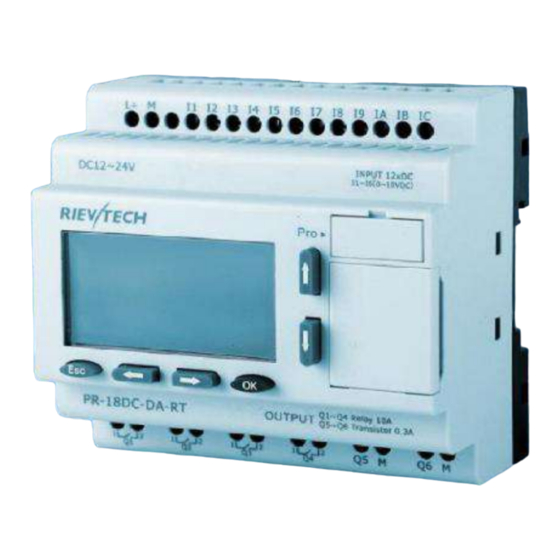
2.3 Structure & dimension 1.Standard PR-12 series with LCD model: 1.Power supply&Input terminals 2. Program Port(can be used as RS232 port with ELC-RS232 or RS485 port with PRO-RS485) 3.HMI/LCD panel 4.keypad 5.Output terminals 2. PR-14 and PR-18 series model: 1.Power supply&Input terminals 2.HMI/LCD panel... - Page 21 Dimensions of PR-14 and PR-18: PR-24 series CPU 1. Power supply 2.Input 3. Program/RS232 port 4.HMI/LCD panel 5.keypad 6.Extension/RS485 port 7.Output...
- Page 22 4.PR-E extension module: 1. Power supply&Input terminals 2. Connection cable between CPU and extension(Detached) 3.Extension port(left) 4. RUN/STOP indicator 5. Extension port( Right) 6. Output terminals Dimensions of PR-E:...
-
Page 23: Installing/Removing Xlogic
PR-E expansion modules have a width of 72mm. l PR-24 Series CPU has a width of 133mm. l PR-12 Series CPU has a width of 72mm W a r n i n g Always switch off power before you “remove” and “insert” an... -
Page 24: Din Rail Mounting
3.1 DIN rail mounting Mounting How to mount a xLogic module and an expansion module onto a DIN rail: 1. Hook the xLogic Basic module onto the rail. 2. Push down the lower end to snap it on. The mounting interlock at the rear must engage. -
Page 25: Wall-Mounting
if you have connected at least one expansion module to xLogic Basic: 1. Remove the connector on the flat cable 2. Slide the expansion module off towards the right. 3. Insert a screwdriver into the eyelet at the bottom of the slide interlock and lever it downward. - Page 26 1. xLogic CPU PR-12 Series CPU PR-14 and PR-18 series: 1.PR-18 CPU;2. PR-E extension...
- Page 27 PR-24 series...
-
Page 28: Wiring Xlogic
3.3 wiring xLogic Wire the xLogic by using a screwdriver with a 3-mm blade. You do not need wire ferrules for the terminals. You can use conductors with cross-sections of up to the following thicknesses: 1 x 2.5 mm2 2 x 1.5 mm2 for each second terminal chamber Tightening torque: 0.4.. -
Page 29: Connecting Xlogic Inputs
To connect xLogic to the power supply: 3.4.1 Connecting xLogic inputs 1.Requirements the inputs you connect sensor elements such as: momentary switches, switches, light barriers, daylight control switches etc. DC Type AC Type Signal status 0 <5VDC <40VAC Input current <0.03mA <0.1mA >79VAC... - Page 30 2. Connecting xLogic is shown as in the following figures: * DC type digital inputs * AC type digital inputs * Analog Inputs (DC 0…10V) *Analog inputs current Inputs (0…20mA)
- Page 31 The above figure shows how to make a four-wire current measurement. PR-E-PT100 It can be connected with one two-wire or three-wire resistance-type the rmocouple. When two-wire technology applied, the terminals “M1+ and IC1” (this rule also shall be applied to” M2+ and IC2”, “M3+ and IC3” ) would be short connected.
-
Page 32: Connecting Xlogic Outputs
2-wire (short circuit M+ and Ic) 3 wire 3.4.2 Connecting xLogic Outputs 1. Requirement for the relay output Various loads such as lamp, fluorescent tube, motor, contact, etc., can be connected to the outputs of xLogic. The maximum ON output current that can be supplied by xLogic is 10A for the resistance load and 3A for the inductive load. - Page 33 2. Requirement for the electronic transistor output: The load connected to xLogic must have the following characteristics: * The maximum switch current cannot exceed 0.3A. * When the switch is ON (Q=1), the maximum current is 0.3A. Notes (PNP): * The load connecting voltage must be ≤60VDC and it must be DC.
- Page 34 PR-E-AQ-VI(DC0..10V analog output). PR-RS485 Actually, PR-RS485 is just a converter with photo isolation bringing out 3 wiring terminals(short circuited inner of such 3 terminals, so only one channel RS485 available) from RS485 port (2x8pin) CPU(PR-18/ELC-22/PR-24) for your easy connection with other devices. If “RT1”, RT2”...
-
Page 35: Communication Port Instructions
3.4.3 Communication port instructions: PR-14,PR-18 ,PR-24 CPUs 1.Programming port/RS232 port (RS232 cable ,USB cable, ELC-MEMORY, ELC-BATTERY,PRO-RS485) should be inserted in this port. When the programming port should be used as the standard RS232 port (D-shape 9 pin header) ,the RS232 cable is needed.Blow is show you the pin definition of the pin:... - Page 36 functi others NULL 1. Expansion port/RS485 ( pin definition) 3------RS485 5------RS485 B 4------GND 6------GND 7------CANL 9------CANH 15------+5V 16------+5V Communication between CPU and expansion module will use 4.7,9,15 pin. PR-RS485 module is required when PR-18/PR-24 CPU communicate with the third party devices via RS485 bus.
-
Page 37: Quick Reference Manual
4.Quick reference manual 4.1 Special memory area: SMB0 Always_On SM0.0 Always ON First_Scan_On SM0.1 ON for the first scan cycle only SMB1 Set to 1 by the execution of certain instructions when Result_0 SM1.0 the operation result = 0 Set to 1 by exec. of certain instructions on overflow Overflow_Illegal SM1.1 or illegal numeric value. - Page 38 high speed counters of different PLC are different.PR-24DC-DA-R PLC and PR-24DC-DAI-RTA PLC have four high speed counters.The input points of high speed counters are I1.0,I1.1,I1.2 and I1.3. HCO,HC1,HC2,HC4 are used for storing the values of high speed counters.
-
Page 39: Direction For Use
X Ladder direction for use 5.The detailed annotation of operation interface 5.1The main menu 5.1.1 File New:New command is used to create a new project, you can use the shortcut CTRL + N to create a new project. Open: Open an existing project, VCW format files, which can be opened by the shortcut CTRL + O. -
Page 40: Edit
5.1.2 Edit Undo : Returns to the last operation,you can send multiple “ undo ” command.If you send out "open" and "off" or "save" or "compile" command, "undo" buffer is cleared.Your next action is recorded as the beginning of a new "undo" order.Can use the shortcut CTRL + Z to undo operation. Redo:Contrary to the function of the undo. - Page 41 LAD: Display the program to LAD instruction. Component:Components include data blocks, system blocks, program editing, function symbols, variable symbols, cross reference and communication settings, will be detailed description of the function of the module in the instruction tree. Symbolic addressing:After the start symbol editing function, it will display the symbol of the annotation.
-
Page 42: Plc
5.1.4 PLC RUN:Make RUN in PLC mode, running the program in PLC, if you use the software to open RUN mode, you need to ensure the normal communication between software and PLC. Stop:Make STOP in PLC mode, to stop the program in the PLC. If you use the software to make STOP into the PLC mode, you need to ensure the normal communication between software and PLC. -
Page 43: Debug
5.1.5 Debug Connect:Display PLC data status in the program editor window. Disconnect:No longer monitor the current value of the PLC data. In offline state does not represent the state of STOP in PLC, if you want to make STOP in PLC state, you can modify the state of PLC in the connection state, in offline state can not be modified. -
Page 44: Toolbar
5.2 toolbar 5.2.1 New:New command is used to create a new project, you can use the shortcut CTRL + N to create a new project. 5.2.2 Open: Open an existing project, VCW format files, which can be opened by the shortcut CTRL + O. Opening the PWM is the PWM format file, can use the shortcut CTRL + P to open. - Page 45 5.2.14 Connect:Display PLC data status in the program editor window. 5.2.15 Disconnect:No longer monitor the current value of the PLC data. In offline state does not represent the state of STOP in PLC, if you want to make STOP in PLC state, you can modify the state of PLC in the connection state, in offline state can not be modified.
- Page 46 Enter the required function block instruction in the dialog box, letters are capital. 5.2.26 Level:The instruction and function blocks are connected in series. 5.2.27 Vertical line:The instruction and function blocks are connected in parallel. 5.2.28 Take back:When the enable input, the output is 0, when the enable to disconnect, the output is 1.
-
Page 47: Instruction Tree
5.3 Instruction tree... -
Page 48: Project
5.3.1 Project You can choose the type of PLC,When PLC type is determined, the PLC parameter will appear below. 5.3.2 Data block Data blocks contain DAT-0 and DAT-1, you can right-click to insert new data blocks for programmers to use .The contents of the data block are as follows: In the data block, you can set the address, data type, data value, and annotation .The contents of the data blocks are written to PLC after a permanent save, unless a new program is written in PLC.The content in the block of data is written to the PLC... -
Page 49: System Block
5.3.3 System block Double click the system block, pop the following interface: RS232 / RS485 interface: All ports are using MODBUS communication protocol.You can set four ports, They are : port 0, port 1, port 2 and port 3. You can set the station number, baud rate, data bit, stop bit, parity, timeout and frame interval time. - Page 50 CAN interface PLC supports CAN communication.CAN communication will be introduced in the communication block.
- Page 51 Password interface Password has 3 levels. Level 1-Full:All PLC functions are available without restriction. Level 2-Minium:You have to enter a password before using each function of PLC. Level 3-Disallow Upload:You can't upload the PLC program.Then you have to enter a password before using each function of PLC. And if you forget the password:...
- Page 52 Retentive Ranges interface By default, all M, T, V, and C storage areas are set to remain.You can redefine the scope and set some storage areas to non - hold.You can define the six holding range, select the storage area you want to keep.You can define the address holding range in the following storage areas.
- Page 53 Interrupt time parameter setting interface: There are two time interrupt events.respectively, the time of the interrupt event 1 and the time of the interrupt event 0. The interrupt time you can set is 1 to 255 milliseconds.
- Page 54 Force table interface: When PLC is converted from RUN mode to STOP mode, the selected output points will be 1.
-
Page 55: Program Block
5.3.4 Program block The program block contains three parts, namely, MAIN (main program), INT-1 (interrupt routine) and SBR-0 (subroutine). Check the interrupt program, right click to add or delete interrupt program. Check the subroutine, right click to add or delete subroutine. The main program can not be added or deleted. -
Page 56: Status Chart
When the address and data types do not match, the address is red. 5.3.7 Status chart Double click the status chart, the pop-up interface is as follows: In the status chart, you can set the address, data type, value, and forced. 5.3.8 Cross reference The cross reference displays the address, symbol, location, and context ,... -
Page 57: Communication
5.3.9 Communication Set the PLC communication, the setting interface is as follows: Serial Port:You can set the station number, port, baud rate, parity and stop bit. MODBUS: PLC doesn’t support the MODBUS TCP/IP function temporarily . CAN KVASER 、CANPRO、CANALSYT -II are three kinds of CAN drivers, you can choose the corresponding CAN driver to use. -
Page 58: Instructions
5.3.10 Instructions Instructions will be explained in detail in the instructions section. -
Page 59: The Program Editor
5.3.11 The program editor Local variable table:It will be described in detail in the PLC X Ladder storage area and variable. Program editing area:In the program editing area, the main program、 interrupt program and subroutine can be edited. -
Page 60: Status Chart, Information Output
5.3.12 Status chart, information output Status Chart: 5.3.7 chapter. Information Output:The output information window keeps a list of errors generated during compilation.When program modification is completed, compile the program again. -
Page 61: Programming Concepts
5.4 Programming concepts 5.4.1 How the program works The program is run by the loop, PLC reads and writes data continuously.When you download the program to PLC and make PLC in the run mode, the PLC' s central processing unit (CPU) executes the program in the following order: A:PLC read input status. - Page 62 of addresses. # symbols in a local variable before #INPUT1 Global symbol name INPUT1 A question mark indicates an undefined address (which must be ??.? or ???? defined before the program is compiled). Global scope and local scope The symbol value in the symbol table has a global scope, and the symbol value in the local variable table has a local scope.
-
Page 63: How To Organize The Program
5.4.3 How to organize the program Basic elements of a control program CPU PR-X control program consists of the following program types: main program The main body of the program is where you place the control application instructions.The instructions in the main program are executed in sequence, and each scan cycle is executed once. -
Page 64: How To Enter The Ladder Logic Program
move,because there is no need to worry about addressing conflicts. interrupt routine You can write an interrupt routine to handle some predefined interrupt events:The interrupt routine is not called by the main program;When the interrupt event occurs, it is called by the PLC operating system.Interrupt routine is best to use local variables. You can use a local variable table to ensure that your interrupt routine uses only temporary memory. -
Page 65: Network Rules For Series And Parallel In Lad
5.5.3 Network rules for series and parallel in LAD Rules for placing contacts Each network must begin with a contact. The network cannot be terminated by contact. Rules for placing coils The network can not start with the coil;The coil is used to terminate the logical network.A network may have a number of coils, and the coils are located on a parallel branch of the network.Could not be connected in series with more than one coil in the network... - Page 66 Instruction will appear in the selected editing area. Use the toolbar button or function key 1.Place the cursor in the position you want to edit in the program editor window. Click the mouse, there will be a selection box. 1.Select the required button in the toolbar Or use the functional keys (F4= contacts, F6= coil, F9= box).
-
Page 67: How To Enter The Address In Lad
5.5.5 How to enter the address in LAD When you enter a command in the LAD, the instruction contains question marks.The question mark indicates that the parameter is not assigned.You can assign values to the parameters of the element when you enter the element.If the parameter is not assigned, the program will not be properly compiled. - Page 68 Edit cells, instructions, addresses, and networks 1.Select an empty cell, you can use the right key to select the operations as follows: 2.Select an instruction, you can use the right key to select the operations as follows:...
- Page 69 3.You can cut and paste elements and rows, delete rows or columns. Delete element: You can use the DELETE or BACKSPACE key to delete the cells;You can select the elements that need to be deleted, use the right key to select the “delete” function component.
-
Page 70: How To Use Find / Replace
5.5.7 How to use find / replace 1.Select Edit > Find , Edit > replace 2. Use the shortcut key CTRL+F to start the search function. How to use search and replace function Search function 1.Enter the string you want to search in the “search content” field. 2.You can use the “Find up”... -
Page 71: How To Display Errors In Lad In The Program Editor
5.5.8 How to display errors in LAD in the program editor Red words display errors. Attention: when you replace the invalid value or symbol with a valid value, the font is automatically changed to the default font color. 5.5.9 How to compile in LAD You can use the toolbar button or the “PLC”... -
Page 72: How To Save The Project
5.5.10 How to save the project You can use the "save" button on the toolbar to save your project, or use the shortcut key CTRL+S to save your project. "Save" allows you to save all changes quickly in your project. “Save as”... - Page 73 2.Select the PLC model: ensure that the PLC model in the software is consistent with the actual PLC model.
-
Page 74: Download Program
3.In this PLC, you can choose 5 kinds of communication.Right click to open the “communication”, the interface is as follows: 5.6.2 Download program If XLadder and PLC communicate successfully,you can download the program to PLC.Steps are as follows: Attention: the new program will cover the old program. Before the program is downloaded to PLC, the program needs to be compiled 2.After the success of the compiler, click the "download"... -
Page 75: How To Correct Compilation Errors And Download Errors
3.When the program is downloaded successfully, the interface is as follows: There are three options,you can chose one of them. 5.When you choose “yes” or “no”, you can click on the “connection” to monitor the program. When you choose “cancel”, PLC is stopped.You can click on the “run” button ,then click on the “connection”... -
Page 76: How To Monitor And Debug The Program
If you have closed the output window, select View > floating window > output window from the menu bar to display the output window again. 5.7 How to monitor and debug the program After the program is downloaded, you can use the "debug" toolbar diagnostic function. - Page 77 simultaneously: PLC data written or forced in the state table window will be applied to the program status monitor window. The conditions of Viewing data status 1.X Ladder and PLC communicate successfully. 2.Download the program to the PLC successfully. 3.To view the continuous changes of the PLC data state , the PLC must be located in the RUN mode.
- Page 78 State values are collected in a continuous manner or snapshot manner Continuity 1.Open the program editor window and start the “program status monitoring".When PLC is in the RUN mode, you can view the continuous state of the program data. 2.Open the status table window and start the “status table monitoring".When PLC is in the RUN mode, you can view the continuous state of the program data.
- Page 79 Mandatory and cancel the mandatory Forced Enter the address and its value that you want to force in the state table. Then select the mandatory function.Before canceling the mandatory, the mandatory function has been effective. "Mandatory" function covers "read immediately " and "write immediately" functions. I/O points can be forced, and other storage areas can not be forced.
-
Page 80: Plc Operation And Options
5.8 PLC operation and options Elements of the control program Ladder Program In the LAD program, the basic elements of the logic are represented by contacts, coils, and boxes. The input is represented by a symbol called a contact.Contact is divided into normally open contact and normally closed contact. -
Page 81: Ladder Instructions Descriptions
6.X Ladder instructions descriptions 6.1 Bit logic 6.1.1 Normally open and normally closed Input / output Operand Data type Bit(LAD、STL) I, Q, M, SM, T, C, V, S, L Boolean Input(FBD) I, Q, M, SM, T, C, V, S, L, Enable bit Boolean Output(FBD)... - Page 82 When the bit is equal to 1, the normally open contact is closed, and the normally closed contact is disconnected. When the bit is equal to 0, the normally open contact is disconnected , and the normally closed contact is closed .
-
Page 83: Normally Open Immediate And Normally Closed Immediate
6.1.2 Normally open immediate and normally closed immediate. When PLC executes the instruction, the immediate instruction obtains the actual input value, but the PLC does not update the process image register. The immediate contact update does not depend on the PLC scan cycle;... -
Page 84: Rising Edge And Falling Edge
6.1.4 Rising edge and falling edge Operand Input / output Data type Input (FBD) I, Q, M, SM, T, C, V, S, L, Enable bit Boolean output(FBD) I, Q, M, SM, T, C, V, S, L, Enable bit Boolean When left logic is converted from 0 to 1,Rising edge contact conduction time is a scan cycle. -
Page 85: Output
6.1.5 Output Operand Input / output Data type I, Q, M, SM, T, C, V, S, L Boolean Input (LAD) Enable bit Boolean Input (FBD) I, Q, M, SM, T, C, V, S, L, Enable bit Boolean The output instruction writes the new value of output bit to process image register. -
Page 86: Set And Reset
The new value generated by executing the immediate output instruction is written to the actual output and the corresponding process image register. 6.1.7 Set and reset Operand Input / output Data type I, Q, M, SM, T, C, V, S, L Boolean VB, IB, QB, MB, SMB, SB, LB, AC, constant, *VD, *AC, *LD Byte... -
Page 87: Set Immediate And Reset Immediate
6.1.8 Set immediate and reset immediate Operand Input / output Data type Boolean VB, IB, QB, MB, SMB, SB, LB, AC, constant, *VD, *AC, *LD Byte “Set immediate” can set many of points immediately. “Reset immediate” can reset many of points immediately. The value of N is between 1 and 128. -
Page 88: Rs Instruction
Example: 6.1.10 RS instruction Operand Input / output Data type S, R1 (LAD) Enable bit Boolean S, R1 (FBD) I, Q, M, SM, T, C, V, S, L, Enable bit Boolean OUT (LAD) Enable bit Boolean OUT (FBD) I, Q, M, SM, T, C, V, S, L, Enable bit Boolean I, Q, M, V, S Boolean... -
Page 89: Nop Instruction
Example: 6.1.11 NOP instruction NOP instruction is invalid for user program execution.Can not use NOP instruction in FBD mode.The value of N is between 0 and 255. -
Page 90: Clock Instruction
6.2 Clock instruction 6.2.1 Read and set the real time clock Operand Input / output Data type VB, IB, QB, MB, SMB, SB, LB, *VD, *AC, *LD Byte TODR instruction reads the current time and date from the hardware clock and load it into the time buffer of 7bytes starting at the address T. -
Page 91: Communication
6.3 Communication 6.3.1 Get port address Operand Input / output Data type ADDR VB, IB, QB, MB, SB, SMB, LB, AC, *VD, *LD, *AC byte PORT Constant(0 or1) byte The GET -ADDR instruction reads the PLC port site from the PORT,and put the value in the address specified in the ADDR. -
Page 92: Compare
6.4 Compare 6.4.1 Byte compare Operand Input / output Data type Input IB, QB, MB, SMB, VB, SB, LB, AC, constant, *VD, *LD, *AC byte output(FBD) I, Q, M, SM, T, C, V, S, L, Boolean Byte comparison instructions are used for comparing two values:IN1 and IN2. - Page 93 2.Enter the illegal real number Example:...
-
Page 94: Integer Comparison
6.4.2 Integer comparison Operand Input / output Data type Input IW, QW, MW, SW, SMW, T, C, VW, LW, AIW, AC, constant, *VD, *LD,*AC Integer output(FBD) I, Q, M, SM, T, C, V, S, L, Enable bit Boolean Comparison instructions are used for comparing two values: IN1 and IN2. -
Page 95: Double Integer Comparison
6.4.3 Double integer comparison Operand Input / output Data type Input ID, QD, MD, SD, SMD, VD, LD, HC, AC, constant, *VD, *LD, *AC Double integer output(FBD)I, Q, M, SM, T, C, V, S, L, Enable bit Boolean Comparison double integer instructions are used for comparing two values:IN1 and IN2. -
Page 96: Real Number Comparison
6.4.4 Real number comparison Operand Input / output Data type Input ID, QD, MD, SD, SMD, VD, LD, AC, constant, *VD, *LD, *AC Real number Output(FBD) I, Q, M, SM, T, C, V, S, L, Enable bit Boolean Comparison real number instructions are used for comparing two values:IN1 and IN2. -
Page 97: String Comparison
6.4.5 String comparison Operand Input / output Data type VB, Constant string, LB, *VD, *LD, *AC String VB, LB, *VD, *LD, *AC String Output(FBD) I, Q, M, SM, T, C, V, S, L, Enable bit Boolean Comparison string instructions are used for comparing two ASCII strings: IN1=IN2,IN1<>IN2 In LAD, when the comparison result is true, the comparison contact will be turned on. -
Page 98: Convert
6.5 Convert 6.5.1 Byte to integer Operand Input / output Data type VB, IB, QB, MB, SB, SMB, LB, AC, constant, *AC, *VD, *LD Byte VW, IW, QW, MW, SW, SMW, LW, AQW, T, C, AC, *VD, *LD, *AC Integer Byte to integer:The B-I instruction converts the byte value to the integer value, and the result is inserted into the variable specified by the OUT.Because the byte does not... -
Page 99: Integer To Byte
6.5.2 Integer to byte Operand Input / output Data type VW, IW, QW, MW, SW, SMW, LW, T, C, AIW, AC, constant, *VD, *LD, *AC Integer VB, IB, QB, MB, SB, SMB, LB, AC, *VD, *AC, *LD Byte nteger to byte:I-B Instruction converts the value of a word to a byte value, and the result is inserted into the variable specified by the OUT.The numerical range is 0 to 255. - Page 100 I-s instruction: the instruction converts the integer word to a ASCII string of 8 characters in length.Format (FMT) specifies the number of digits to the right of the decimal point.The result string is written in 9 consecutive bytes from the OUT. Illegal format(nnn >...
-
Page 101: Double Integer To Integer
6.5.5 Double integer to integer Operand Input/output Data type VD, ID, QD, MD, SD, SMD, LD, HC, AC, constant, *VD, *LD, *AC Double integer VW, IW, QW, MW, SW, SMW, LW, AQW, T, C, AC, *VD, *LD, *AC Integer Double integer to integer I-I instruction converts the :... -
Page 102: Double Integer To String
6.5.7 Double integer to string Operand Input/output Data type VD, ID, QD, MD, SD, SMD, LD, HC, constant, AC, *VD, *AC, *LD Double integer VB, IB, QB, MB, SB, SMB, LB, constant, AC, *VD, *LD, *AC Byte VB, *VD, LB, *AC, *LD String Double integer to string :DI-s instruction: the instruction... -
Page 103: Bcd To Integer, Integer To Bcd Conversion
NNN is greater than 5, the output is displayed as a string of 12 ASCII space characters. C decides to use a comma or a decimal point between integer and decimal .The 4 bits above the top of the format must be zero. 6.5.8 BCD to integer, integer to BCD conversion Operand Input/output... -
Page 104: Round
6.5.9 ROUND Operand Input/output Data type VD, ID, QD, MD, SD, SMD, LD, AC, constant, *VD, *LD, *AC Real number VD, ID, QD, MD, SD, SMD, LD, AC, *VD, *LD, *AC Double integer The ROUND instruction converts the real number value to a double integer value and the result is inserted into the variable specified by the OUT. -
Page 105: Trunc
6.5.10 TRUNC Operand Input/output Data type VD, ID, QD, MD, SD, SMD, LD, AC, constant, *VD, *LD, *AC Real number VD, ID, QD, MD, SD, SMD, LD, AC, *VD, *AC, *LD Double integer TRUNC:Instruction converts 32 bits of real number to 32 bits integer,and the result is inserted into the variable specified by the OUT. -
Page 106: Real Number To String
6.5.11 Real number to string Operand Input/output Data type VD, ID, QD, MD, SD, SMD, LD, constant, AC, *VD, *LD, *AC Real number VB, IB, QB, MB, SB, SMB, LB, constant, AC, *VD, *LD, *AC Byte VB, LB, *VD, *AC, *LD String R-S:Instruction converts the real number value to a ASCII string.(FMT) format specifies the conversion accuracy of... - Page 107 The following is the RTS instruction format (FMT) operand definition: ssss = The length of the output string c = Comma (1) or decimal point (0) nnn = The number of characters of the right of the decimal point. The length of the output string is specified by the SSSS field.0, 1, or 2 bytes are not valid.The effective range of the NNN is from 0 to 5.NNN is equal to 0, the output shows no decimal point.When the NNN value is greater than 5 or when the specified output string length is too small to store the conversion value, the output string is...
-
Page 108: Integer To Ascii Code
6.5.12 Integer to ASCII code Data type Input/output Operand VW, IW, QW, MW, SW, SMW, LW, AIW, T, C, AC, constant, *VD, *LD, *AC Integer VB, IB, QB, MB, SB, SMB, LB, AC, constant, *VD, *LD, *AC byte VB, IB, QB, MB, SB, SMB, LB, *VD, *LD, *AC byte ITA:The instruction converts the integer word to ASCII characters. - Page 109 Example: Example: As shown in Figure:The integer input is 123;nnn=1 The output value is as follows: 16#33 16#2E 16#32 16#31 16#20 Space 16#20 Space 16#20 Space 16#20 Space...
-
Page 110: Double Integer To Ascii Code
6.5.13 Double integer to ASCII code Input/output Operand Data type VD, ID, QD, MD, SD, SMD, LD, HC, constant, AC, *VD, *AC, *LD Double integer VB, IB, QB, MB, SB, SMB, LB, AC, constant, *VD, *LD, *AC Byte VB, IB, QB, MB, SB, SMB, LB, *VD, *LD, *AC Byte The instruction converts the double integer to ASCII DTA:... -
Page 111: Real Number To Ascii Code
6.5.14 Real number to ASCII code Input/output Operand Data type VD, ID, QD, MD, SD, SMD, LD, AC, constant, *VD, *LD, *AC Real number VB, IB, QB, MB, SB, SMB, LB, AC, constant, *VD, *LD, *AC Byte VB, IB, QB, MB, SB, SMB, LB, *VD, *LD, *AC Byte RTA:The instruction converts the real number to ASCII characters. - Page 112 The size of the output string must be 3 bytes larger than “nnn”. The value in the output string must be aligned to the right. Example: Example: Convert the real number 123.45 into ASCII code.The output is 6 bytes . The output: 16#31 16#32...
-
Page 113: Ath&Hta
6.5.15 ATH&HTA Input/output Operand Data type IN,OUT VB, IB, QB, MB, SB, SMB, LB, *VD, *AC, *LD Byte VB, IB, QB, MB, SB, SMB, LB, AC,constant, *VD, *LD, *AC Byte ASCII to HEX Instruction converts the ASCII characters starting with “IN”to the hexadecimal digits starting with the “out”.The maximum length of the ASCII string is 255 characters. -
Page 114: String To Integer
6.5.16 String to integer Input/output Operand Data type VB,constant string, LB, *VD, *LD, *AC String INDX VB, IB, QB, MB, SB, SMB, LB,constant, AC,*VD, *LD, *AC Byte VW, IW, QW, MW, SW, SMW, LW, T, C, AQW, AC, *VD, *LD, *AC Integer S-I:The instruction converts the string value “IN”... - Page 115 The following table shows examples of valid and invalid integer input strings: Example: Enter the string "12@45”.The S-I instruction converts the string from the first character, and the result is an integer 12.
-
Page 116: String To Double Integer
6.5.17 String to double integer Input/output Operand Data type VB,constant string, LB, *VD, *LD, *AC String INDX VB, IB, QB, MB, SB, SMB, LB,constant, AC,*VD, *LD, *AC Byte VD, ID, QD, MD, SD, SMD, LD, AC, *VD, *LD, *AC Double integer S- DI:The instruction converts the string value “IN”... - Page 117 The following table shows examples of valid and invalid integer input strings: Example: Enter the string "123B5”.The S- DI instruction converts the string from the first character, and the result is a double integer 123. Because B is an invalid character, the characters after B are no longer converted.
-
Page 118: String To Real Number
6.5.18 String to real number Input/output Operand Data type VB,constant string, LB, *VD, *LD, *AC String INDX VB, IB, QB, MB, SB, SMB, LB,Constant, AC,*VD, *LD, *AC Byte VD, ID, QD, MD, SD, SMD, LD, AC, *VD, *LD, *AC Real number S-R:The instruction converts the string value “IN”... - Page 119 This instruction does not generate overflow errors, but only converts the string to real number and then terminates the conversion. For example, the string "1.234E6" will be converted to a real number value “1.234”without generating an error message. The following table shows examples of valid and invalid integer input strings: Example: Input string “2.345”...
-
Page 120: Deco
6.5.19 DECO Input/output Operand Data type VB, IB, QB, MB, SMB, LB, SB, AC, constant, *VD, *LD, *AC Byte VW, IW, QW, MW, SMW, LW, SW, AQW, T, C, AC, *VD, *AC, *LD word The low four bits value of input byte is n, the nth bit of the output word is equal to 1. -
Page 121: Enco
6.5.20 ENCO Input/output Operand Data type VW, IW, QW, MW, SMW, LW, SW, AIW, T, C, AC, constant, *VD, *AC, *LD Word VB, IB, QB, MB, SMB, LB, SB, AC, *VD, *LD, *AC Byte The nth bit of the input word is equal to 1.The low ENCO: four bits value of output byte is n. -
Page 122: Seven Segment Code
6.5.21 Seven segment code Input/output Operand Data type VB, IB, QB, MB, SB, SMB, LB, AC,constant, *VD, *AC, *LD Byte VB, IB, QB, MB, SMB, LB, AC, *VD, *AC, SB, *LD Byte SEG:The instruction generates the bits of the seven segment. -
Page 123: Counter
6.6 Counter 6.6.1 CTU Input/output Operand Data type C xxx Constant(C0—C255) Word CU (LAD) Enable bit Boolean CU (FBD) I, Q, M, SM, T, C, V, S, L, Enable bit Boolean R (LAD) Enable bit Boolean R (FBD) I, Q, M, SM, T, C, V, S, L,Enable bit Boolean VW, IW, QW, MW, SMW, LW, AIW, AC, T, C,constant, *VD, *AC, *LD, SW Integer CU bit gets a high level and the current value of the... -
Page 124: Ctd
6.6.2 CTD Input/output Operand Data type Cxxx Constant(C0—C255) Word CD (LAD) Enable bit Boolean CD (FBD) I, Q, M, SM, T, C, V, S, L,Enable bit Boolean LD (LAD) Enable bit Boolean LD (FBD) I, Q, M, SM, T, C, V, S, L,Enable bit Boolean VW, IW, QW, MW, LW, SMW, AC, T, C, AIW,constant, *VD, *AC, *LD, SW Integer The bit of CD is converted from 0 to 1 and the current... -
Page 125: Ctud
6.6.3 CTUD Input/output Operand Data type C xxx Constant(C0—C255) word CU, CD (LAD) Enable bit Boolean CU, CD (FBD) I, Q, M, SM, T, C, V, S, L,Enable bit Boolean R (LAD) Enable bit Boolean R (FBD) I, Q, M, SM, T, C, V, S, L,Enable bit Boolean VW, IW, QW, MW, LW, SMW, AC, T, C, AIW,constant, *VD, *AC, *LD, SW Integer CU bit gets a high level and the current value of the... -
Page 126: Floating Point Calculation
6.7 Floating point calculation 6.7.1 ADD-R&SUB-R Input/output Operand Data type IN1, IN2 VD, ID, QD, MD, SD, SMD, LD, AC,constant, *VD, *LD, *AC Real number VD, ID, QD, MD, SD, SMD, LD, AC, *VD, *LD, *AC Real number ADD-R:Adding N1 and N2, the result is put into the output buffer. - Page 127 Example:...
-
Page 128: Mul - R&Div - R
6.7.2 MUL - R&DIV - R Input/output Operand Data type IN1, IN2 VD, ID, QD, MD, SMD, SD, LD, AC,constant, *VD, *LD, *AC Real number VD, ID, QD, MD, SMD, SD, LD, AC, *VD, *LD, *AC Real number MUL - R:IN1 multiplied by IN2, the result is put into the output buffer. -
Page 129: Sqrt
Example: 6.7.3 SQRT Input/output Operand Data type VD, ID, QD, MD, SMD, SD, LD, AC,constant, *VD, *LD, *AC Real number VD, ID, QD, MD, SMD, SD, LD, AC, *VD, *LD, *AC Real number SQRT:Enter a 32 bits real number(IN).Take “IN” square root and output 32 bits real number. -
Page 130: Sin
6.7.4 SIN Input/output Operand Data type VD, ID, QD, MD, SMD, SD, LD, AC,constant, *VD, *LD, *AC Real number VD, ID, QD, MD, SMD, SD, LD, AC, *VD, *LD, *AC Real number SIN:Perform trigonometric operations on the input radian value and put the result into OUT.You can use the angle value multiplied by 1.745329E-2 to get the value of the radian.The value of the input “IN”... -
Page 131: Cos
6.7.5 COS Input/output Operand Data type VD, ID, QD, MD, SMD, SD, LD, AC,constant, *VD, *LD, *AC Real number VD, ID, QD, MD, SMD, SD, LD, AC, *VD, *LD, *AC Real number COS:Perform trigonometric operations on the input radian value and put the result into OUT.You can use the angle value multiplied by 1.745329E-2 to get the value of the radian.The value of the input “IN”... -
Page 132: Tan
6.7.6 TAN Input/output Operand Data type VD, ID, QD, MD, SMD, SD, LD, AC,constant, *VD, *LD, *AC Real number VD, ID, QD, MD, SMD, SD, LD, AC, *VD, *LD, *AC Real number :Perform trigonometric operations on the input radian value and put the result into OUT.You can use the angle value multiplied by 1.745329E-2 to get the value of the radian.The value of the input “IN”... - Page 133 6.7.7 LN Input/output Operand Data type VD, ID, QD, MD, SMD, SD, LD, AC,constant, *VD, *LD, *AC Real number VD, ID, QD, MD, SMD, SD, LD, AC, *VD, *LD, *AC Real number LN: Use the input value to perform natural logarithm calculation and put the result in OUT.
-
Page 134: Exp
6.7.8 EXP Input/output Operand Data type VD, ID, QD, MD, SMD, SD, LD, AC,constant, *VD, *LD, *AC Real number VD, ID, QD, MD, SMD, SD, LD, AC, *VD, *LD, *AC Real number EXP:Input value is N and output value is N is a real number. -
Page 135: Pid
6.7.9 PID Input/output Operand Data type Byte LOOP Constant(0 to 7) Byte According to the parameters in the TBL,PID instruction performs the PID operation.Up to 8 PID instructions can be used in the program,the value of LOOP is the loop number of PID.PID loop number can not be the same, otherwise it will cause interference.Parameters in the TBL parameter table... - Page 136 Mathematical formula of PID loop instruction: = MP + MI + MD : Output value : Proportion term : Integral term : Differential term Proportion term * (SP - PV : Proportion term • • : gain : Set point •...
- Page 137 : gain • • : Differential time Sampling time • • : Last time process variable : Process variable •...
-
Page 138: Integer Operations
6.8 Integer operations 6.8.1 ADD-I&SUB-I Input/output Operand Data type IN1, IN2 VW, IW, QW, MW, SW, SMW, T, C, AC, LW, AIW,constant, *VD, *LD, *AC Integer VW, IW, QW, MW, SW, SMW, T, C, LW, AC, *VD, *LD, *AC Integer ADD-I: IN1 + IN2 = OUT Both input and output are 16 bits integers. - Page 139 Special memory bit: SM1.0 Zero result overflow SM1.1 SM1.2 Negative result Example :...
-
Page 140: Add- Di & Sub- Di
6.8.2 ADD- DI & SUB- DI Input/output Operand Data type IN1, IN2 VD, ID, QD, MD, SMD, SD, LD, AC, HC,Constant, *VD, *LD, *AC Double integer VD, ID, QD, MD, SMD, SD, LD, AC, *VD, *LD, *AC Double integer Both input and output are 32 ADD- DI: IN1 + IN2 = OUT bits integers. -
Page 141: Mul & Div
6.8.3 MUL & DIV Input/output Operand Data type IN1, IN2 VW, IW, QW, MW, SW, SMW, T, C, LW, AC, AIW,constant, *VD, *LD, *AC Integer VD, ID, QD, MD, SMD, SD, LD, AC, *VD, *LD, *AC Double Integer MUL:IN1 X IN2= OUT Input 16 bits integers and output 32 bits integer. -
Page 142: Mul -I & Div-I
Example: 6.8.4 MUL -I & DIV-I Input/output Operand Data type IN1, IN2 VW, IW, QW, MW, SW, SMW, T, C, LW, AC, AIW,constant, *VD, *LD, *Ac Integer VW, IW, QW, MW, SW, SMW, LW, T, C, AC, *VD, *LD, *AC Integer MUL -I: IN1 * IN2 = OUT Both input and output are 16 bits integers. - Page 143 Special memory bit: SM1.0 Zero result SM1.1 overflow SM1.2 Negative result SM1.3 The divisor is 0 Example:...
-
Page 144: Mul -Di & Div -Di
6.8.5 MUL -DI & DIV -DI Input/output Operand Data type IN1, IN2 VD, ID, QD, MD, SMD, SD, LD, HC, AC,constant, *VD, *LD, *AC Double integer VD, ID, QD, MD, SMD, SD, LD, AC, *VD, *LD, *AC Double integer MUL -DI: Both input and output are 32 IN1 * IN2 = OUT bits integers. -
Page 145: Inc-B & Dec-B
6.8.6 INC-B & DEC-B Input/output Operand Data type VB, IB, QB, MB, SB, SMB, LB, AC,constant, *VD, *LD, *AC Byte VB, IB, QB, MB, SB, SMB, LB, AC, *VD, *LD, *AC Byte INC-B: IN + 1 = OUT Both input and output are 8 bits integers. -
Page 146: Inc-W & Dec-W
6.8.7 INC-W & DEC-W Input/output Operand Data type VW, IW, QW, MW, SW, SMW, AC, AIW, LW, T, C,constant, *VD, *LD, *AC Integer VW, IW, QW, MW, SW, SMW, LW, AC, T, C, *VD, *LD, *AC Integer INC-W: IN + 1 = OUT Both input and output are 16 bits integers. -
Page 147: Inc -Dw & Dec -Dw
6.8.8 INC -DW & DEC -DW Input/output Operand Data type VD, ID, QD, MD, SD, SMD, LD, AC, HC,constant, *VD, *LD, *AC Double integer VD, ID, QD, MD, SD, SMD, LD, AC, *VD, *LD, *AC Double integer INC -DW: IN + 1 = OUT Both input and output are 32 bits double integers. -
Page 148: Interrupt
6.9 Interrupt 6.9.1 ENI & DISI Operand Data type Nothing Nothing Interrupt enable ( ENI) :If the instruction is activated, all interrupts can be used. Interrupt disable(DISI):If the instruction is activated, all interrupts can not be used. When the DISI instruction is used, the interrupt events will be queued. - Page 149 Example:...
-
Page 150: Reti Instruction
6.9.2 RETI instruction Operand Data type Nothing Nothing RETI: When the Logic in front of the RETI instruction is 1, PLC execution returns from interrupt. Interrupt Events: I1.2 Rising edge PLC_EVENT_INPUTP0 Highest priority I1.4 Rising edge PLC_EVENT_INPUTP1 High priority Timer interrupt 0 PLC_EVENT_TIMER0 Low priority Timer interrupt 1... -
Page 151: Atch
6.9.3 ATCH Input/output Operand Data type Constant 0-127 Byte EVNT Constant 0-33 Byte ATCH:The interrupt event (EVNT) is connected to the interrupt routine number (INT) by the “ATCH” instruction , and then activates the interrupt event. You can attach more than one interrupt events to an interrupt routine.However, an interrupt event can not be attached to the multiple interrupt routines.When you attach an interrupt event to an interrupt routine, the interrupt is automatically enabled.When the DISI instruction is used, the interrupt events will be queued. - Page 152 Example: “ATCH” instruction only needs to be connected once.
-
Page 153: Dtch
6.9.4 DTCH Input/output Operand Data type EVNT Constant(0-33) Byte Interrupt separation (DTCH) instruction cancels the association between interrupt event (EVNT) and interrupt routine, and disables the interrupt event. The interrupt event (EVNT) is connected to the interrupt routine number (INT) by the “ATCH” instruction , and then activates the interrupt event. - Page 154 Example:...
-
Page 155: Clear Interrupt Event
6.9.5 Clear interrupt event Input/output Operand Data type EVNT Constant Byte CLR - EVNT instruction will remove all types of EVNT interrupt events in interrupt queue. This instruction is used for removing unnecessary interrupts. Interrupt Events: I1.2 Rising edge PLC_EVENT_INPUTP0 Highest priority I1.4 Rising edge PLC_EVENT_INPUTP1... -
Page 156: Logic Operation
6.10 Logic operation 6.10.1 INV -B Input/output Operand Data type VB, IB, QB, MB, SB, SMB, LB, AC,constant, *VD, *AC, *LD Byte VB, IB, QB, MB, SB, SMB, LB, AC, *VD, *AC, *LD Byte INV -B: The instruction performs the complement operation to the input byte and puts the result in OUT. -
Page 157: Inv -W
6.10.2 INV -W Input/output Operand Data type VW, IW, QW, MW, SW, SMW, T, C, AIW, LW, AC,constant, *VD, *AC, *LD word VW, IW, QW, MW, SW, SMW, T, C, LW, AC, *VD, *AC, *LD word INV -W:The instruction performs the complement operation to the input word and puts the result in OUT. -
Page 158: Inv -Dw
6.10.3 INV -DW Input/output Operand Data type VD, ID, QD, MD, SD, SMD, LD, HC, AC,constant, *VD, *AC, *LD Double word VD, ID, QD, MD, SD, SMD, LD, AC, *VD, *AC, *LD Double word INV -DW:The instruction performs the complement operation to the input word and puts the result in OUT. -
Page 159: Wand-B、Wor -B、Wxor -B
6.10.4 WAND-B、WOR -B、WXOR -B Input/output Operand Data type IN1, IN2 VB, IB, QB, MB, SB, SMB, LB, AC,constant, *VD, *AC, *LD Byte VB, IB, QB, MB, SB, SMB, LB, AC, *VD, *AC, *LD Byte WAND -B:The instruction performs “And calculation” on IN1 and IN2.Then puts the result in out. -
Page 160: Wand-W、Wor -W、Wxor -W
WAND-W、WOR -W、WXOR -W 6.10.5 Input/output Operand Data type IN1, IN2 VW, IW, QW, MW, SW, SMW, T, C, AC, LW, AIW,constant, *VD, *AC, *LD word VW, IW, QW, MW, SW, SMW, T, C, LW, AC, *VD, *AC, *LD word WAND -W:The instruction performs “And calculation” on IN1 and IN2.Then puts the result in out. -
Page 161: Wand- Dw、Wor -Dw、Wxor -Dw
6.10.6 WAND- DW、WOR -DW、WXOR -DW Input/output Operand Data type IN1, IN2 VD, ID, QD, MD, SMD, AC, LD, HC,constant, *VD, *AC, SD, *LD Double word VD, ID, QD, MD, SMD, LD, AC, *VD, *AC, SD, *LD Double word WAND -DW:The instruction performs “And calculation” on IN1 and IN2.Then puts the result in out. -
Page 162: Move
6.11 Move 6.11.1 Byte move Input/output Operand Data type VB, IB, QB, MB, SB, SMB, LB, AC,constant, *VD, *LD, *AC Byte VB, IB, QB, MB, SB, SMB, LB, AC, *VD, *LD, *AC Byte MOV -B:The instruction moves the input byte (IN) to the output byte (OUT), which does not change the original value. -
Page 163: Word Move
6.11.2 Word move Input/output Operand Data type VW, IW, QW, MW, SW, SMW, LW, T, C, AIW, constant, AC, *VD, *AC, *LD word、 integer VW, T, C, IW, QW, SW, MW, SMW, LW, AC, AQW, *VD, *AC, *LD word、 integer MOV -W:The instruction moves the input word (IN) to the output word (OUT), which does not change the original value. -
Page 164: Double Word Move
6.11.3 Double word move Input/output Operand Data type VD, ID, QD, MD, SD, SMD, LD, HC, &VB, &IB, &QB, &MB, &SB, &T, &C, &SMB, &AIW, &AQW AC, constant, *VD, *LD, *AC Double word, double integer VD, ID, QD, MD, SD, SMD, LD, AC, *VD, *LD, *AC Double word, double integer MOV -DW:The instruction moves the input double word (IN) to the output double word (OUT), which does not... -
Page 165: Real Number Move
6.11.4 Real number move Input/output Operand Data type VD, ID, QD, MD, SD, SMD, LD, AC,constant, *VD, *LD, *AC Real number VD, ID, QD, MD, SD, SMD, LD, AC, *VD, *LD, *AC Real number MOV -R:The instruction moves the input real number (IN) to the output real number (OUT), which does not change the original value. -
Page 166: Blkmov
6.11.5 BLKMOV -B Input/output Operand Data type VB, IB, QB, MB, SB, SMB, LB, *VD, *AC, *LD Byte VB, IB, QB, MB, SB, SMB, LB, AC,constant, *VD, *AC, *LD Byte VB, IB, QB, MB, SB, SMB, LB, *VD, *AC, *LD Byte These successive“N”bytes which start with “IN”... -
Page 167: Blkmov
6.11.6 BLKMOV -W Input/output Operand Data type VW, IW, QW, MW, SW, SMW, LW, T, C, AIW, *VD, *LD, *AC word VB, IB, QB, MB, SB, SMB, LB, AC,constant, *VD, *LD, *AC byte VW, IW, QW, MW, SW, SMW, LW, T, C, AQW, *VD, *LD, *AC word BLKMOV -W:These successive“N”words which start with “IN”... -
Page 168: Blkmov -D
6.11.7 BLKMOV -D Input/output Operand Data type IN, OUT VD, ID, QD, MD, SD, SMD, LD, *VD, *AC, *LD Double word VB, IB, QB, MB, SB, SMB, LB, AC,constant, *VD, *AC, *LD Byte BLKMOV - D:These successive“N”double words which start with “IN” are moved to OUT. The range of N is from 1 to 255. -
Page 169: Swap
6.11.8 SWAP Input/output Operand Data type VW, IW, QW, MW, SW, SMW, T, C, LW, AC, *VD, *AC, *LD word SWAP:The instruction interchanges high byte and low byte of the input word. error conditions: 0006 Indirect address Example:... -
Page 170: Mov -Bir
6.11.9 MOV -BIR Input/output Operand Data type IB, *VD, *LD, *AC Byte VB, IB, QB, MB, SB, SMB, LB, AC, *VD, *AC, *LD byte MOV -BIR:Instruction reads the actual input value(byte),then writes the value to OUT. The process image register is not updated. -
Page 171: Program Control
6.12 Program control 6.12.1 FOR、NEXT Input/output Operand Data type INDX VW, IW, QW, MW, SW, SMW, LW, T, C, AC, *VD, *LD, *AC Integer INIT VW, IW, QW, MW, SW, SMW, T, C, AC, LW, AIW,constant, *VD, *LD, *AC Integer FINAL VW, IW, QW, MW, SW, SMW, LW, T, C, AC, AIW,constant, *VD, *LD, *AC Integer... - Page 172 Example: Notes: Cycle times are set to 100 times.At the end of the cycle, the value of VW100 is 100.
-
Page 173: Jump To Label And Label
6.12.2 Jump to label and label Input/output Data type n:constant(0~255) word JMP instruction performs the branch operation to the program in the specified tag (n) . When the jump is accepted, the top value of the stack is 1. LBL instruction signs the location of n. You can use the "jump"... -
Page 174: Sequence Control Relay
6.12.3 Sequence control relay Input/output Operand Data type Boolean SCR instruction is good at dealing with repetitive operations. SCR: load the SCR section, you can use the SET instruction. SCRT: Jump to another SCR segment and close the current SCR segment. SCRE: The instruction signs the end of SCR segment. -
Page 176: Return From Subroutine
6.12.4 Return from subroutine RET: Return from the subroutine to the main program. Example: Main program: Subroutine: When the M0.0 bit is 1, return from the subroutine, the following program will no longer be scanned. -
Page 177: Conditional End
6.12.5 Conditional end The END instruction terminates the user program . Notes: You can use the "END" instruction in the main program, but can not be used in subroutine or interrupt routine. Example: When the M0.1 bit is 1, the program will not be scanned. -
Page 178: Stop
6.12.6 STOP STOP instruction:STOP Example: When the M0.1 bit is 1, PLC converts to the STOP mode, all the programs stop running. -
Page 179: Watchdog Reset
6.12.7 Watchdog Reset WDR clear watchdog time.When the scan cycle is greater than the watchdog time, the WDR makes the watchdog not issue a warning. Using “WDR” instruction should be careful.The following programs can be performed after the scan cycle is completed. 1.Communication 2.I/O update (except for immediate I/O) 3.Forced update... -
Page 180: Diagnosis Led
6.12.8 Diagnosis LED Input/output Operand Data type VB, IB, QB, MB, SB, SMB, LB, AC,constant, *VD, *LD, *AC String If the value of “EN” is 1, then the LCD will display the string from “IN”. Example: When the value of M0.0 is equal to 1,the LCD will display “Error”. -
Page 181: Shift Cycle
6.13 Shift cycle 6.13.1 SHR -B & SHL -B Input/output Operand Data type IN (LAD, FBD) VB, IB, QB, MB, SB, SMB, LB, AC,constant, *VD, *LD, *AC Byte VB, IB, QB, MB, SB, SMB, LB, AC,constant, *VD, *LD, *AC Byte VB, IB, QB, MB, SB, SMB, LB, AC, *VD, *LD, *AC Byte SHR -B:Input byte "IN"... - Page 182 Example: When the value of M0.0 is 1, VB0 moves a bit towards the left and VB10 moves a bit towards the right.
-
Page 183: Shr -W & Shl -W
6.13.2 SHR -W & SHL -W Input/output Operand Data type IN (LAD, FBD) VW, IW, QW, MW, SW, SMW, LW, T, C, AIW, AC,constant, *VD, *LD, *AC word VB, IB, QB, MB, SB, SMB, LB, AC,constant, *VD, *LD, *AC byte VW, IW, QW, MW, SW, SMW, LW, T, C, AC, *VD, *LD, *AC word SHR -W:Input word "IN"... -
Page 184: Shr -Dw & Shl -Dw
SHR -DW & SHL -DW 6.13.3 Input/output Operand Data type IN (LAD, FBD) VD, ID, QD, MD, SD, SMD, LD, AC, HC,constant, *VD, *LD, *AC Double word VB, IB, QB, MB, SB, SMB, LB, AC,constant, *VD, *LD, *AC Double word VD, ID, QD, MD, SD, SMD, LD, AC, *VD, *LD, *AC Double word SHR -DW:Input double word "IN"... -
Page 185: Ror -B & Rol -B
6.13.4 ROR -B & ROL -B Input/output Operand Data type IN (LAD, FBD) VB, IB, QB, MB, SMB, SB, LB, AC,constant, *VD, *LD, *AC Byte VB, IB, QB, MB, SMB, SB, LB, AC,constant, *VD, *LD, *AC Byte VB, IB, QB, MB, SMB, SB, LB, AC, *VD, *LD, *AC Byte ROR -B &... -
Page 186: Ror -W & Rol -W
ROR -W & ROL -W 6.13.5 Input/output Operand Data type IN (LAD, FBD) VW, T, C, IW, QW, MW, SW, SMW, LW, AC, AIW,constant, *VD, *LD, *AC word VB, IB, QB, MB, SB, SMB, LB, AC,constant, *VD, *LD, *AC byte VW, T, C, IW, QW, MW, SW, SMW, LW, AC, *VD, *LD, *AC word ROR -W &... -
Page 187: Ror -Dw & Rol -Dw
6.13.6 ROR -DW & ROL -DW Input/output Operand Data type IN (LAD, FBD) VD, ID, QD, MD, SD, SMD, LD, AC, HC,constant, *VD, *LD, *AC Double word VB, IB, QB, MB, SB, SMB, LB, AC,constant, *VD, *LD, *AC Byte VD, ID, QD, MD, SD, SMD, LD, AC, *VD, *LD, *AC Double word ROR -DW &... -
Page 188: Shrb
6.13.7 SHRB Input/output Operand Data type DATA, S_BIT I, Q, M, SM, T, C, V, S, L Boolean VB, IB, QB, MB, SB, SMB, LB, AC,constant, *VD, *LD, *AC Boolean SHRB instruction moves the DATA value to the shift register. S_BIT specifies the lowest bit of the shift register.N specifies the length of the shift register and the shift direction (shift plus = N, shift minus = -N).The moved out bit is placed in the overflow memory bit (SM1.1).The... -
Page 189: Character String
6.14 Character string 6.14.1 String length Input/output Operand Data type VB,Constant string, LB, *VD, *LD, *AC Character string VB, IB, QB, MB, SB, SMB, LB, AC, *VD, *LD, *AC Byte STR-LEN:Instruction output “IN” string length. The longest constant string is 126 bytes. error conditions: 0006 Indirect address 0091 Operand range... -
Page 190: Copy String
6.14.2 Copy string Input/output Operand Data type VB, Constant string, LB, *VD, *LD, *AC Character string VB, *VD, LB, *LD, *AC Character string STR-CPY:Instruction copies the “IN” string to the “OUT” string. The longest constant string is 126 bytes. error conditions: 0006 Indirect address 0091 Operand range ASCII constant string data type format:... -
Page 191: Sstr-Cpy
6.14.3 SSTR-CPY Input/output Operand Data type Iput VB,Constant string, LB, *VD, *LD, *AC string INDX, N VB, IB, QB, MB, SB, SMB, LB, AC,constant, *VD, *LD, *AC byte VB, *VD, LB, *LD, *AC string SSTR-CPY:Copy a portion of the input string to the OUT string.If the value of INDX is X,copy the string starting from the xth character.The length of the copy string is N. -
Page 192: String Catenate
6.14.4 String catenate Input/output Operand Data type Input VB,Constant string, LB, *VD, *LD, *AC String VB, LB, *VD, *LD, *AC String STR -CAT:Add the string specified by the IN to the string specified by the OUT. The longest constant string is 126 bytes. error conditions: 0006 Indirect address 0091 Operand range... -
Page 193: Str -Find
6.14.5 STR -FIND Input/output Operand Data type IN1, IN2 VB, constant string, LB, *VD, *LD, *AC string VB, IB, QB, MB, SB, SMB, LB, AC, *VD, *LD, *AC byte STR -FIND:The instruction searches for the string IN2 in the string IN1 .Search starts from the OUT start position.If you find a string that is the same as the string IN2, the first character position of the string is written to the OUT.If you do not find IN2 in IN1,OUT is set to 0.The... -
Page 194: Look For The First Character In The String
6.14.6 Look for the first character in the string Input/output Operand Data type IN1, IN2 VB,constant string, LB, *VD, *LD, *AC string VB, IB, QB, MB, SB, SMB, LB, AC, *VD, *LD, *AC byte CHR -FIND: The instruction searches for the same character as the string IN2 in the string IN1.Search starts from the OUT start position.If a match character is found, the character position is written to OUT.If a match character is... -
Page 195: Table
6.15 Table 6.15.1 Last in first out Input/output Operand Data type VW, IW, QW, MW, SW, SMW, LW, T, C, *VD, *LD, *AC word DATA VW, IW, QW, MW, SW, SMW, LW, AC, T, C, AQW, *VD, *LD, *AC integer LIFO:Instruction moves the latest (or last) entry in the table to the output memory address.Remove the last entry in the table (TBL) and move the value to the location... - Page 196 For example: PLC program: Data block: Analysis: When the value of M0.0 is equal to 1, the last entry of the table will be deleted and the value of the last entry of the table will be moved to “VW300”. When the value of M0.0 is equal to 1 : VW202=3 VW210 is invalid...
-
Page 197: Fifo
6.15.2 FIFO Input/output Operand Data type VW, IW, QW, MW, SW, SMW, LW, T, C, *VD, *LD, *AC word DATA VW, IW, QW, MW, SW, SMW, LW, AC, T, C, AQW, *VD, *LD, *AC integer FIFO:Remove the first entry in the table (TBL) and move the value to the location specified by DATA.All other entries in the table move a location upward.Each time the instruction is executed,the number of entries in the table... - Page 198 For example: PLC program: Data block: Analysis: When the value of M0.0 is equal to 1, the first entry of the table will be deleted and the value of the first entry of the table will be moved to “VW300”. When the value of M0.0 is equal to 1 : VW202=3 VW210 is invalid...
-
Page 199: Add To Table
6.15.3 Add to table Input/output Operand Data type DATA VW, IW, QW, MW, SW, SMW, LW, T, C, AIW, AC,constant, *VD, *LD, *AC integer VW, IW, QW, MW, SW, SMW, LW, T, C, *VD, , *LD *AC word AD -T- TBL:The instruction adds the word (DATA) to the table (TBL).The first value in the table is the maximum length of the table .The second value is the entry count (EC),it specifies the number of entries in the table.Each... - Page 200 When the value of M0.0 is equal to 1: The value of VW202 + 1 The Table will have a new entry The value of the new entry is equal to the value of VW300.
-
Page 201: Memory Fill
6.15.4 Memory fill Input/output Operand Data type VW, IW, QW, MW, SW, SMW, LW, T, C, AIW, AC,constant, *VD, *LD, *AC integer VB, IB, QB, MB, SB, SMB, LB, AC,constant, *VD, *LD, *AC byte VW, IW, QW, MW, SW, SMW, LW, T, C, AQW, *VD, *LD, *AC integer FILL-N: The input value of “IN”... -
Page 202: Table Find
6.15.5 Table Find Input/output Operand Data type VW, IW, QW, MW, SW, SMW, LW, T, C, *VD, *LD, *AC word VW, IW, QW, MW, SW, SMW, AIW, LW, T, C, AC,constant, *VD, *LD, *AC integer INDX VW, IW, QW, MW, SW, SMW, LW, T, C, AC, *VD, *LD, *AC word Table Find instruction:The instruction searches the same data as “PTN”... - Page 203 Data block: When the value of M0.0 is equal to 1: The table format of the “Table-Find” begins with the entry count.It doesn’t have the “maximum number of entries”: VW202 Entry Count VW204 Data 0 VW206 Data 1 VW208 Data 2 VW210 Data 3...
-
Page 204: Timer
6.16 Timer 6.16.1 Switch on delay timer Input/output Operand Data type Txxx constant(T0 -T255) word IN (LAD) Enable bit Boolean IN (FBD) I, Q, M, SM, T, C, V, S, L,Enable bit Boolean VW, IW, QW, MW, SW, SMW, LW, AIW, T, C, AC,constant, *VD, *LD, *AC integer TON:When the value of the input “IN”... - Page 205 T101~T127 6553.5 Attention: 1.The value of each timer TXXX is different. 2.The resolution of the timer depends on the time base.For example, the error range of the 10 millisecond timer is 10 milliseconds. Example:...
-
Page 206: Tonr
6.16.2 TONR Input/output Operand Data type Txxx Constant(T0—T255) word IN (LAD) Enable bit Boolean IN (FBD) I, Q, M, SM, T, C, V, S, L,Enable bit Boolean VW, IW, QW, MW, SW, SMW, LW, AIW, T, C, AC,constant, *VD, *LD, *AC Integer TONR:When the value of the input “IN”... -
Page 207: Disconnect Delay Timer
6.16.3 Disconnect delay timer Input/output Operand Data type Txxx constant(T0—T255) word IN (LAD) Enable bit Boolean IN (FBD) I, Q, M, SM, T, C, V, S, L,Enable bit Boolean VW, IW, QW, MW, SW, SMW, LW, AIW, T, C, AC,constant, *VD, *LD, *AC Integer TOF: When the input is closed, the output will be closed for a period of time.When the value of IN is 1, the bit of the timer is 1 Immediately and timer current value is set to... -
Page 208: Start Time Interval
6.16.4 Start time interval Input/output Operand Data type VD, ID, QD, MD, SMD, SD, LD, AC, *VD, *LD, *AC Double word Reads the current value of the built-in 1 ms counter and stores it in the OUT. Example: The value of VD4 is the conduction time of M0.0... -
Page 209: Calculation Interval Time
6.16.5 Calculation interval time Input/output Operand Data type VD, ID, QD, MD, SMD, SD, LD, HC, AC, *VD, *LD, *AC Double word VD, ID, QD, MD, SMD, SD, LD, AC, *VD, *LD, *AC Double word Calculates the time difference between the current time and the time provided by the IN, and stores the time difference in the OUT. -
Page 210: Pulse Train Output
6.17 Pulse train output 6.17.1 Pulse output Input/output Operand Data type Double integer ID, QD, AID, AQD, MD, VD, HC, SMD, LD, *MD, *VD, *LD Double integer ID, QD, AID, AQD, MD, VD, HC, SMD, LD, *MD, *VD, *LD QX.X PLSY:When the value of the enable bit is 1,Instruction issues N pulses.The pulse frequency is F. - Page 211 For example: Attention: Output point must be high speed output point. For different PLC,the addresses of high speed output points may be different.
-
Page 212: Pulse Width Modulation
6.17.2 Pulse width modulation Input/output Operand Data type IW, QW, AIW, AQW, MW, VW, T, C, SMW, LW, *MD, *VD, *LD Double word IW, QW, AIW, AQW, MW, VW, T, C, SMW, LW, *MD, *VD, *LD Double word Pulse width modulation (PWM) instruction initializes the PWM hardware and sends high speed pulses. -
Page 213: Subroutine
6.18 Subroutine 6.18.1 Using subroutine Subroutine is used for program partitioning.When the main program calls subroutine and performs the subroutine,subroutine executes all instructions to the end.Then, the system returns to the main program. Subroutine is used for program partitioning.It helps to read and manage programs. It also helps to debug and maintain programs.You can use PLC more effectively by using subroutine.Because all of the subroutine blocks are not scanned when they are not called. -
Page 214: Using Parameters To Call Subroutine
6.18.2 Using parameters to call subroutine Subroutine may contain the transfer parameters.The parameter is defined in the local variable table of the subroutine.Parameters must have a symbol name (up to 23 characters), a variable type, and a data type.Each subroutine can be set up to 16 IN/OUT parameters. -
Page 215: How To Set Up A Subroutine
Integer, double integer Input or output parameters with symbols. Real number It identifies single precision floating point values. String This data type is used as a four byte pointer to the string. Enable bit Boolean enable bit can be used only for bit.It can be used as input. -
Page 216: How To Call A Subroutine
6.18.4 How to call a subroutine You can call a subroutine from the main program, another subroutine or an interrupt routine;You can’t call the subroutine from the subroutine itself. In LAD, the subroutine generates a block instruction.You can call the block instruction to call the subroutine. - Page 217 Example:Four arithmetic operation Main program:...
- Page 218 Subroutine:...
-
Page 219: Plc Storage Area
7.PLC storage area 7.1 Storage area types and properties Byte Word Double Retain Force Region Illustration Word Read / Read / Read / Read / Discrete write write write write input image register Read / Read / Read / Read / Discrete write write... -
Page 220: Direct And Indirect Addressing
Read / Read / Read / Read / write write write write 7.2 Direct and indirect addressing When you write the program, you can use the three ways to address instruction: 1.Direct addressing 2.Symbol addressing 3.indirect addressing Direct addressing PLC can directly specify the memory area, size, and location; In order to read/write a bit in the memory area, you need to specify the address. - Page 221 Symbolic addressing Symbol addressing consists of letters, numbers and characters. You can set the symbol of address by the following steps: You can enter “start” as the address of I0.0 Indirect addressing Indirect addressing uses pointer to access the data of memory. Pointer is a double word.It contains the address of another memory location.
- Page 222 Pointer consists of memory location and symbol "&”. To specify the operand be a pointer , you should input an asterisk (*) in front of the operand. Example:The values stored in the VB200 and VB201 are moved to AC0. As shown in the figure below, you can change the pointer value.Because the pointer is a 32 bit value, you should use the double word instruction to modify the pointer value.
-
Page 223: Bit, Byte, Word And Double Word Access
interval is 4. If the value of the pointer is greater than the maximum value of the V memory, program will generate errors. The current value of the timer and counter is 16 bits,so the minimum pointer interval is 2. 7.3 Bit, byte, word and double word access Bit access If you want to access a bit, you need to specify the address of the... -
Page 224: Data Type
S0.0~S31. SB0~SB31 SW0~SW SD0~SD2 SM0.0~S SMB0~SM SMW0~S SMD0~S M551.7 B551 MW550 MD548 T0~T255 T0~T255 C0~C255 C0~C255 V0.0~V81 VB0~VB8 VW0~VW VD0~VD8 91.7 8190 L0.0~L63. LB0~LB63 LW0~LW6 LD0~LD6 AC0~AC3 AC0~AC3 AC0~AC3 HC0~HC1 7.5 Data type Data Type Data width Range BOOL BYTE 16#00~16#FF WORD 16#0000~16#FFFF... -
Page 225: Constant
DINT -2147483648~2147483647 USINT 0~255 UINT 0~65535 UDINT 0~4294967295 7.6 Constant Unsigned integer range Signed integer range Data size: Decimal digit:Hexadecimal digit: Decimal digit: Hexadecimal digit: B(byte) 0~255 0~FF -128 ~+127 80~7F W(word) 0~65535 0~FFFF -32768~+32767 8000~7FFF D(double word)0~4294967295 0~FFFF FFFF -2147483648 8000 0000~ ~+2147483647... -
Page 226: Assignment And Function Of Sm Special Storage Area
8.Assignment and function of SM special storage area SMB0 Always_On SM0.0 Always ON First_Scan_On SM0.1 ON for the first scan cycle only Clock_60s SM0.4 30 seconds OFF,30 seconds ON Clock_1s SM0.5 0.5 second OFF,0.5 second ON SMB1 Set to 1 by the execution of certain instructions when Result_0 SM1.0 the operation result = 0... -
Page 227: Easy Ladder Communication
9.Easy ladder communication 9.1 PR series PLC basic introduction of network communication PR series PLC is designed to solve your communications and networking needs.It supports both simple networks and complex networks .Easy ladder makes it simple to set up and configure your network . Master slave network definition PR series PLC supports master slave network.It can be used as the master station or the slave station in the network.Easy ladder is always used as the master station. - Page 228 You can set the station number, port, baud rate, parity and stop bit of easy ladder.The default station number is 0.The default baud rate is 9600 bps. Set the baud rate and network address of PR series PLC Open system block in project management You can set the station number, baud rate, data bits, parity bit and stop bit of PLC.
-
Page 229: Pr Series Plc Communication
Attention:Only when Easy Ladder software station number is equal to 0 or PLC station number,you can download the program to PLC. 9.2 PR series PLC communication PR series PLC support free port communication, MODBUS communication and CAN communication. Free port communication: Free port communication is a half duplex communication based on RS-485 communication.Users can make their own communication protocol in free port communication.Third party devices mostly support RS-485 serial communication . - Page 230 (Instruction input)M200.4 Send CRC check (Instruction input)M200.5 Receive CRC check (Instruction input)M200.6 Receive CRC check (Instruction output) MB201 Error number: 0indicates no error. l RCV: receive data,If the input is MB400: (Instruction input) MW400: Receive data FIFO buffer size (byte unit) (Instruction output)...
- Page 231 l XMT Send data FIFO,If the input is MB400: (Instruction input)MW400 Sending data FIFO buffer size (byte unit) (Instruction input)MW402 Sending data size (byte) (Instruction input)MB404 ~ … Send data. UFP_QAR UFP_QAR: Sending and receiving data instruction l PORT Communication port. l TBL: Configuration table,If the input is MB200.
- Page 232 l RCV receive data FIFO,If the input is MB400: (Instruction input)MW400 Receive data FIFO buffer size (byte unit) (Instruction output)MW402 The size of the received data (byte unit) (Instruction output)MB404 ~ … Receive data. UFP_RCV、UFP_XMT、UFP_QAR error numbers: l 1 Port doesn’t exist l 2 Port isn’t enabled l 3 Communication task queue is full l 4 Table error...
- Page 233 MODBUS communication protocol MODBUS protocol is a common language used in electronic controllers.Different devices can communicate with each other by using the MODBUS communication protocol. It has become a general industrial standard.You can use it to connect different devices. This protocol defines a message structure, no matter what network they use to communicate.It describes the process of controller requesting to access other devices.It has formulated message domain structure and the common format of the content.
- Page 234 For example:Query the MODBUS address of Q0.0 : MODBUS instructions: UMB03 Read more than one hold registers l EN:enable or not enable l TBL:Configuration table,If the input is MB200: MB200 is the configuration word ( Instruction Output ) M200.0 Communications have been queued (Instruction Output )M200.1 Communication completion (Instruction Output)M200.2 Communication error...
- Page 235 UMB04 Read the input register l EN:enable or not enable l TBL:Configuration table,If the input is MB200: MB200 is the configuration word ( Instruction Output ) M200.0 Communications have been queued (Instruction Output )M200.1 Communication completion (Instruction Output)M200.2 Communication error (Instruction Output)MB201 is error number.0 indicates no error.
- Page 236 UMB16 Write more than one hold registers l EN:enable or not enable l TBL:Configuration table,If the input is MB200: MB200 is the configuration word (Instruction Output )M200.0 Communications have been queued (Instruction Output )M200.1 Communication completion (Instruction Output)M200.2 Communication error (Instruction Output)MB201 is error number.0 indicates no error.
-
Page 237: Optimize Network Performance
9.3 Optimize network performance The following factors will affect the performance of the network(The baud rate and the master station produce the greatest impact to the performance of the network): Baud rate:It determines the speed of network communication. Number of master stations on the network:To enhance network performance,you can reduce the number of main stations on the network.Each station on the network will increase the additional requirements of the network. -
Page 238: Additional Chapter
10.Additional chapter 10.1 How to switch PLC mode Ladder diagram→FBD 1.Ensure that there is no power supply to the PLC. 2.Press ESC key and UP key,Keep pressing. 3.Power supply to PLC.Keep pressing until the following picture appears. 4.Release the hand, press the OK key FBD→Ladder diagram Repeat the above steps. -
Page 239: Value Range Of Analog Quantity
10.2 Value range of analog quantity: 0~10v → 0~1000 0~20ma →0~1000 4~20ma →0~1000 -50℃~200℃→-500~2000 When you use the PT100 module,The value range of the analog quantity is -500~2000.It corresponds to the temperature that is -50℃~200℃. 10.3 Extension module address You can use the dial switch to set the address.The address of each extension module can not be the same. -
Page 240: Plc Host Address Range
Analog quantity input extension address table: Extension Address Start Address Analog quantity output extension address table: Extension Address Start Address 10.4 PLC host address range Digital input:I0.0~I1.7 Digital output:Q0.0~Q1.7 Analog input:AIW0~AIW18 Analog output:AQW0~AQW18 10.5 Formula Digital quantity extension addressing formula =I(... -
Page 241: Set Extension Module Address With A Dial Switch
=AIW( 10+10) Extension Address × Analog input Start Address =AQW( 10+10) Extension Address × Analog output Start Address Up to 16 extension modules can be connected. 10.6 Set extension module address with a dial switch The address of extension module = The value of dial switch + 1 Dial switch Value →... -
Page 242: Additional Instructions
10.7 Additional instructions 10.7.1 LCD related instructions LCD_KEY LCD_KEY binds LCD keys and PLC variables. l EN:Enable l MODIFY:Modifies the corresponding variables. l ENTER:Confirms the corresponding variables. l UP:The corresponding variable of UP key. l DOWN:The corresponding variable of DOWN key. l LEFT:The corresponding variable of LEFT key. - Page 243 Supplementary explanation:MASK input is a byte.Take VB0 as an example: When 0 bit is equal to 1, LCD will display 0 group. When 1 bit is equal to 1, LCD will display 1 group. When 2 bit is equal to 1, LCD will display 2 group. When 7 bit is equal to 1, LCD will display 7 group.
- Page 244 For example: You have to edit display pages in LCD software. Display page 1: Display page 2: Display page 3: Display page 4:...
- Page 245 Grouping of display pages in display page property: Display page 1:Display page 1 is divided into 0 group and 1 group. Display page 2:Display page 2 is divided into 0 group and 1 group. Display page 3:Display page 3 is divided into 0 group. Display page 4:Display page 4 is divided into 0 group.
- Page 246 PLC program: Analysis: In network 0,the program binds LCD keys and PLC variables. PLC has ten function keys.Each function key corresponds to a PLC variable. F1 corresponds to SM191.0 F2 corresponds to SM191.1 F3 corresponds to SM191.2...
- Page 247 F4 corresponds to SM191.3 ESC corresponds to SM190.0 corresponds to SM190.1 corresponds to SM190.2 DOWN corresponds to SM190.3 LEFT corresponds to SM190.4 RIGHT corresponds to SM190.5 NETWORK 0: MODIFY is ESC function key,corresponds to SM190.0 The functions of function keys: You can customize F1~F4.
- Page 248 VB200 is 1.0 bit is equal to 1,so LCD displays 0 group.The value of VB201 is 0, which means the first display page.The first display page is display page 1. You can use the program to specify the display group and the display page . For example: The LCD will display group 1 and display page2.
- Page 249 For example: When you modify the first variable of display page 1: The instruction will display as follows: Vb205 = 0 Variable 0,the first variable. Vb206 = 1 It means that you can use LCD function keys to edit variables. Vb207 = 1 It means you can modify single digit.Vb207 = 2,you can modify single digit and tens digit.
- Page 250 For example: Modify the value of variable to 161. For example: Modify text list VB205 Variable 1, the second variable. VB206 It means that you can use LCD function keys to edit variables. VB207 Edit depth is 1. VB208 LOOP VB209 No flicker VD210...
-
Page 251: Can, Serial Port Initialization Instructions
10.7.2 CAN, serial port initialization instructions UART_Init CAN_Init CAN_Init instruction is used to initialize the CAN port. l EN:If the input value is 1,the instruction will initialize the CAN port. l PORT:port number,0~1。 l BR:CAN port baud rate UART_Init instruction is used to initialize the serial port. l EN:If the input value is equal to 1,the instruction will initialize the serial port. -
Page 252: Example Of Serial Port Free Port Communication
10.8 Example of serial port free port communication Program 1 :... - Page 253 Explain:Send data 11 22 33 44 per second through port 1.And record the counts of sending data. Program 2: Explain:Receive data through port 1.The maximum length of the data is 100 bytes.
-
Page 254: Example Of Can Free Port
10.9 Example of CAN free port... - Page 255 Explain:The state of the I0.0 is transmitted through port 0.Receive data VB106 through port0. The state of the first bit of VB106 is the state of Q0.0...
-
Page 256: Modbus Communication Master Program
10.10 MODBUS communication master program Read multiple hold registers and write multiple hold registers... -
Page 257: The Example Of Using Pid Instruction
10.11 The example of using PID instruction The initialization of PID parameters VD112 gain VD116 Sampling time VD120 Integral time VD124 Differential time... - Page 258 Conversion of Process quantity and set value unit...
- Page 259 Call a PID command every 0.3 seconds.
- Page 260 The conversion of output value unit .
Need help?
Do you have a question about the PR-12 Series and is the answer not in the manual?
Questions and answers