GRAPHTEC gl7000 User Manual
Module-expanding, high speed, multi-function, multi-channel data platform
Hide thumbs
Also See for gl7000:
- Study manual (37 pages) ,
- Quick start manual (24 pages) ,
- User manual (8 pages)
Table of Contents
Advertisement
Advertisement
Table of Contents

Related Manuals for GRAPHTEC gl7000


Summary of Contents for GRAPHTEC gl7000
- Page 1 GL7000 DATA PLATFORM USER’S MANUAL MANUAL NO.GL7000-UM-154...
-
Page 3: Conventions Used In This Manual
To Ensure Safe and Correct Use To Ensure Safe and Correct Use • To ensure safe and correct use of the GL7000, read this Manual thoroughly before use. • After having read this Manual, keep it in a handy location for quick reference as needed. • Do not permit small children to touch the GL7000. • The following describes important points for safe operation. Please be sure to observe them strictly. Conventions Used in This Manual To promote safe and accurate use of the GL7000 as well as to prevent human injury and property damage,safety precautions provided in this manual are ranked into the five categories described below. Be sure you understand the difference between each of the categories. -
Page 4: Safety Precautions
• connect its male plug into the electrical socket. Use of the GL7000 in such status may result in a fire hazard • U se of the GL7000 without the power cord securely plugged or electrical shock. • into the electrical socket may result in electrical shock due to A fter checking that smoke is no longer being generated, current leakage. - Page 5 Clean off any soiled areas using a soft dry cloth. No lubrication No volatile solvent To ensure safe and correct use of your GL7000, read this manual thoroughly before use. If the equipment is used in a manner not specified by the manufacture, the protection provided by the equipment may be impaired.
-
Page 7: Introduction
Introduction Introduction Thank you for purchasing the GL7000 DATA PLATFORM. Please read this manual thoroughly before attempting to use your new product to ensure that you use it correctly and to its full potential. Notes on Use Be sure to read all of the following notes before attempting to use the GL7000 DATA PLATFORM. 1. Note on the CE Marking The GL7000 complies with the EN61326 (Class A) standard based on the EMC directive (2004/108/EC). It also conforms to the EN61010-1 standard based on the LV directive (2006/95/EC). Although the GL7000 complies with the above-mentioned standards, be sure to use it correctly in accordance with the instructions and notes provided in its User’s Manual. Moreover, use of the GL7000 by incorrect procedures may result in damage to the GL7000 or may invalidate its safeguards. Please confirm all of its notes regarding use and other related information to ensure correct use. - Page 8 (6) Measured results may not conform to the stated specifications if the GL7000 is used in an environment which is subject to strong electromagnetic interference. (7) Insofar as possible, position the GL7000 input signal cables away from any other cables which are likely to be affected by electromagnetic interference. (8) For stabilized measurement, allow the GL7000 to warm up for at least 30 minutes after turning it on. About Registered Trademarks • Microsoft and Windows are registered trademarks or trademarks of Microsoft Corporation in the U.S. and elsewhere.
-
Page 9: Table Of Contents
......2-17 Installing the Display Module (GL7-DISP: optional) and GL7000 .... - Page 10 CONTENTS Connecting the Power Cable and Turning on the Power ......2-28 ............2-28 When using AC power .
- Page 11 CONTENTS 3-129 ............(17) File operations 3-130 .
-
Page 13: Chapter 1 General Description
CHAPTER 1 General Description CHAPTER 1 General Description This chapter provides a general description of the GL7000 and its features. 1.1 Overvie 1.2 Features 1.3 Operating Environment 1.4 Notes on Temperature Measurement (Optional) 1.5 Notes on Using the Monitor 1.6 Changing the Display Language 1.7 Explanation of symbols used on the equipment... -
Page 14: Overvie
CHAPTER 1 General Description 1.1 Overvie The GL7000 is a module-expanding, high speed, multi-function, multi-channel DATA PLATFORM. A maximum of 10 Amplifier Modules can be expanded, and expansion of an SSD Module and a Display Module makes it suitable for all sorts of needs. In addition to being able record measuring data on the built-in RAM, it also comes equipped with a large capacity flash memory. Since recording can be done to an SD card, transferring data to the PC when offline is easy. -
Page 15: Operating Environment
Measurement of factory line. AIf condensation occurs... Condensation occurs in the form of water droplets on the device surfaces and interior when the GL7000 is moved from a cold to a warm location. Using the GL7000 with condensation will cause malfunctioning. Wait until the condensation has disappeared before turning on the power. -
Page 16: Configuration When In Use
CHAPTER 1 General Description Configuration When in Use It is recommended to use the main module while it is laid flat or inclined on the stands. < Usage Configuration> • To prevent possible malfunction, do not block the air vents of the main module. •... -
Page 17: Notes On Temperature Measurement (Optional)
If the screen saver operates, press any key to restore the display. • Condensation may form on the LCD screen if the GL7000 is moved from a cold to a warm location. If this occurs, wait until the LCD screen warms up to room temperature. -
Page 18: Changing The Display Language
• In the label seal of top panel on • If the measured value is unstable due to the each measurement modules exogenous noise, it is probably better that the (Ground) (optional). cables are thicker between the GND terminal Terminal of DUT and the GND terminal of GL7000. In addition, the both GND terminals should be connected to the earth for same potential level. • If a voltage exceeding the specified value is input, the main unit will be damaged. Alternating • In product identification label of • Be sure to connect the main unit to an AC right side on the main unit. -
Page 19: Chapter 2 Checks And Preparation
CHAPTER 2 Checks and Preparation CHAPTER 2 Checks and Preparation This chapter explains how to check the main module's external casing and accessories, and how to prepare the main module for operation. 2.1 Checking the Outer Casing 2.2 Checking the Accessories 2.3 Checking the Optional Modules 2.4 Checking the Optional Accessories 2.5 Main module Nomenclature and Functions 2.6 Module Nomenclature and Functions... -
Page 20: Checking The Outer Casing
CHAPTER 2 Checks and Preparation 2.1 Checking the Outer Casing After unpacking, check the GL7000's outer casing before use. In particular, please check for the following: • Surface scratches • Other flaws such as stains or dirt 2.2 Checking the Accessories After unpacking, check that the following standard accessories are included. -
Page 21: Checking The Optional Accessories
CHAPTER 2 Checks and Preparation 2.4 Checking the Optional Accessories Optional Accessories Item Model Description Sync cable for GL7000 B-559 Sync cable between devices Probe for logic/pulse RIC-10 4ch input (Set of alligator clip and IC clip) BNC-BNC cable RIC-112 1.5 m, 60VDC or less BNC-Banana cable RIC-113 1.5 m, 60VDC or less BNC-Alligator cable RIC-114 1.5 m, 60VDC or less Safe probe RIC-141A 1:1 42pF, Length 1.2 m, 300VDC, CAT II... -
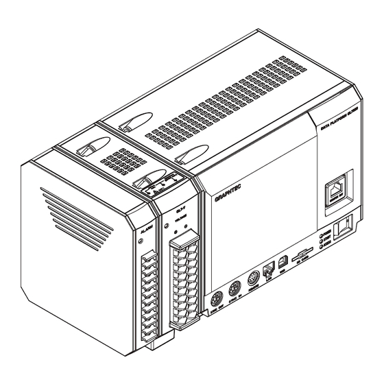
Page 22: Main Module Nomenclature And Functions
CHAPTER 2 Checks and Preparation 2.5 Main module Nomenclature and Functions This section describes the names and function of parts of the main module (Separately, an optional amplifier module is needed). The Alarm module has been connected to the GL7000 main module at shipping. Alarm module Main module 1. Module fixing screw (upper) (Inside the cover) 15. Alarm signal output terminal 2. Face cover 10. Cooling fan... - Page 23 1. Module fixing screw (upper) ..Fixation screw for the adjoining module. To prevent drop off, please refrain from removing it from the module. 2. Face cover ........Remove when the Display Module (optional) is mounted on the main module. 3. Monitor-out connector ....Connector for connecting the Display Module (optional). (When using the tilting table and when extending the cable) 4. Synchronous connection terminal ..........Using the GL7000 sync cable (optional), the multiple GL7000 main modules are synchronized. (Synchronization function is available in GL-Connection only.) 5. REMOTE terminal ....Manages the main module when using input cable for GL (optional). 6. PC I/F terminals......Performs communications between the main module and PC (application) when using a USB/LAN cable. 7. SD CARD slot ......For inserting an SD CARD.
-
Page 24: Module Nomenclature And Functions
CHAPTER 2 Checks and Preparation 2.6 Module Nomenclature and Functions This section describes the names and function of parts of the Module. • When installing or removing modules, please make sure that the power is turned off. • Adequate precautions against static electricity must be taken when handling the modules. • After installation, please make sure to tighten the screws. If using without tightening the screws, the module may break off during use. Display Module (GL7-DISP): Optional • Since the touch-panel in this module is a capacitive touch-panel, it does not respond by touching it with a pen. Touch the finger without glove. • Adequate precautions against static electricity must be taken when handling the modules. Please note that if the touch-panel is operated with an object with a sharp edge, it may scratch and damage the touch-panel. • Do not touch when your hands are wet. <Display module (GL7-DISP) set contents> • Display module : 1 module •... - Page 25 CHAPTER 2 Checks and Preparation 1. Monitor ........LCD monitor equipped with a touch-panel function. 2. Operation key ......Key operation is performed on the screen. * Almost all operations can be performed on the touch-panel or from operation key. 3. Threaded hole for mounting ..Threaded hole for fixing to the main module. 4. Connector for connecting to Module ..........Connector for connecting to the main module. 5. Threaded hole for mounting ..Threaded hole for fixing to the tilting table (2 places). 6. Nail ...........Nails for fixing to the main module (2 places).
-
Page 26: Ssd Module (Gl7-Ssd): Optional
CHAPTER 2 Checks and Preparation SSD Module (GL7-SSD): Optional 4. Cooling fan 3. Module fixing screw (upper) 1. Connector for connecting 8. Access lamp 2. Connector for connecting to main module to module 7. M4 threaded hole 6. Nail 5. Module fixing screw (lower) 1. Connector for connecting to module ..........Connector for connecting to the various modules. 2. Connector for connecting to main module ..........Connector for connecting to the main module. 3. Module fixing screw (upper) ..Fixation screw for the adjoining module. To prevent drop off, please refrain from removing it from the module. -
Page 27: Voltage Module (Gl7-V): Optional
9. Analog signal input terminals 5. Module fixing screw (lower) 1. Connector for connecting to module ..........Connector for connecting to the various modules. 2. Connector for connecting to main module ..........Connector for connecting to the GL7000 main module or various modules. 3. Module fixing screw (upper) ..Fixation screw for the adjoining module. 4. Cooling fan .......Fan to cool internally. 5. Module fixing screw (lower) ..Fixation screw for the adjoining module. 6. Nail ...........A nail for aiding in positioning when connecting the module. 7. M4 threaded hole ......Use this hole to mount to the panel, etc. -
Page 28: High Speed Voltage Module (Gl7-Hsv): Optional
9. Analog signal input terminals 5. Module fixing screw (lower) 1. Connector for connecting to module ..........Connector for connecting to the various modules. 2. Connector for connecting to main module ..........Connector for connecting to the GL7000 main module or various modules. 3. Module fixing screw (upper) ..Fixation screw for the adjoining module. 4. Cooling fan .......Fan to cool internally. 5. Module fixing screw (lower) ..Fixation screw for the adjoining module. 6. Nail ...........A nail for aiding in positioning when connecting the module. 7. M4 threaded hole ......Use this hole to mount to the panel, etc. -
Page 29: Voltage/Temperature Module (Gl7-M): Optional
9. Analog signal input terminals 5. Module fixing screw (lower) 1. Connector for connecting to module ..........Connector for connecting to the various modules. 2. Connector for connecting to main module ..........Connector for connecting to the GL7000 main module or various modules. 3. Module fixing screw (upper) ..Fixation screw for the adjoining module. 4. Cooling fan .......Fan to cool internally. 5. Module fixing screw (lower) ..Fixation screw for the adjoining module. 6. Nail ...........A nail for aiding in positioning when connecting the module. 7. M4 threaded hole ......Use this hole to mount to the panel, etc. -
Page 30: Logic/Pulse Module (Gl7-L/P): Optional
6. Nail 9. Logic pulse signal input terminals 5. Module fixing screw (lower) 1. Connector for connecting to module ..........Connector for connecting to the various modules. 2. Connector for connecting to main module ..........Connector for connecting to the GL7000 main module or various modules. 3. Module fixing screw (upper) ..Fixation screw for the adjoining module. To prevent drop off, please refrain from removing it from the module. 4. Cooling fan .......Fan to cool internally. 5. Module fixing screw (lower) ..Fixation screw for the adjoining module. 6. Nail ...........A nail for aiding in positioning when connecting the module. 7. M4 threaded hole ......Use this hole to mount to the panel, etc. -
Page 31: High Voltage Module (Gl7-Hv): Optional
9. Analog signal input terminals 5. Module fixing screw (lower) 1. Connector for connecting to module ..........Connector for connecting to the various modules. 2. Connector for connecting to main module ..........Connector for connecting to the GL7000 main module or various modules. 3. Module fixing screw (upper) ..Fixation screw for the adjoining module. 4. Cooling fan .......Fan to cool internally. 5. Module fixing screw (lower) ..Fixation screw for the adjoining module. 6. Nail ...........A nail for aiding in positioning when connecting the module. 7. M4 threaded hole ......Use this hole to mount to the panel, etc. -
Page 32: Dc Strain Module (Gl7-Dcb): Optional
5. Module fixing screw (lower) 1. Connector for connecting to module ..........Connector for connecting to the various modules. 2. Connector for connecting to main module ..........Connector for connecting to the GL7000 main module or various modules. 3. Module fixing screw (upper) ..Fixation screw for the adjoining module. 4. Cooling fan .......Fan to cool internally. 5. Module fixing screw (lower) ..Fixation screw for the adjoining module. 6. Nail ...........A nail for aiding in positioning when connecting the module. 7. M4 threaded hole ......Use this hole to mount to the panel, etc. -
Page 33: Charge Module (Gl7-Cha): Optional
(Integrated Electric Piezo Electric) 5. Module fixing screw (lower) 1. Connector for connecting to module ..........Connector for connecting to the various modules. 2. Connector for connecting to main module ..........Connector for connecting to the GL7000 main module or various modules. 3. Module fixing screw (upper) ..Fixation screw for the adjoining module. 4. Cooling fan .......Fan to cool internally. 5. Module fixing screw (lower) ..Fixation screw for the adjoining module. 6. Nail ...........A nail for aiding in positioning when connecting the module. -
Page 34: Voltage Output Module (Gl7-Dco): Optional
9. Voltage output terminal 5. Module fixing screw (lower) 1. Connector for connecting to module ..........Connector for connecting to the various modules. 2. Connector for connecting to main module ..........Connector for connecting to the GL7000 main module or various modules. 3. Module fixing screw (upper) ..Fixation screw for the adjoining module. 4. Cooling fan .......Fan to cool internally. 5. Module fixing screw (lower) ..Fixation screw for the adjoining module. 6. Nail ...........A nail for aiding in positioning when connecting the module. 7. M4 threaded hole ......Use this hole to mount to the panel, etc. -
Page 35: Installing And Removing The Module
Please note that the setting conditions are initialized when changing the configuration of the amplifier module for measurement. Installing the Display Module (GL7-DISP: optional) and GL7000 The Display Module has 3 basic configurations when in use. A: When installing the main module: Assembled to the main module configuration. - Page 36 CHAPTER 2 Checks and Preparation (3) Join the nails on the back of the Display Module with the inset part of the main module, and push it in. (4) Join the Display Module with the module connector, and insert into the main module. (5) Attach the fixation screws of the main module (2 places on the side). Using the screw removed when the face cover is removed, secure it. During installation, a 4kgf/cm screw tightening torque is recommended. Since the touch-screen on the main module is calibrated when turning on power, do not touch it at power-up. When turning on power while touching the touch-panel, the touch panel may not start properly.
- Page 37 CHAPTER 2 Checks and Preparation B: This explains how to attach the tilting table for use. When installing or removing modules, please make sure that the power is turned off. (After removing the main module face cover) Tilting table Monitor connection cable (40 cm) Ground cable (1) Install by binding the monitor connection cable with the clamp on the tilting table. Bind so that the there is approx. 25 cm between the monitor connection cable and the connector. (2) Attach the Display Module to the tilting table with the attached fixation screws (2 places) During installation, a 4kgf/cm screw tightening torque is recommended.
- Page 38 CHAPTER 2 Checks and Preparation (4) Connect the monitor connection cable to the monitor out connector of the main module and attach the 4 point nails on the tilting table by fixing them to inset part of the main module (4 places). Monitor-out connector (5) Attach the fixation screws on the main module (2 places on the side). Using the screw removed when the face cover is removed, secure it.
- Page 39 CHAPTER 2 Checks and Preparation C: This explains installation when extending cables. When installing or removing modules, please make sure that the power is turned off. (After the main module's face cover is mounted) (1) Connect the monitor out contact on the main module and the monitor in contact on the Display Module with a commercially available LAN cable.
-
Page 40: Installing The Amplifier Module For Measurement (Optional) And Main Module
CHAPTER 2 Checks and Preparation Installing the amplifier module for measurement (optional) and main module • When installing or removing modules, please make sure that the power is turned off. • Please note that the setting conditions are initialized when changing the configuration of the amplifier module for measurement. - Page 41 CHAPTER 2 Checks and Preparation (3) Connect the connector by sliding it parallel to the main module. Slide it in the direction of the arrow. If you pry it at an angle there is a risk of damaging the nail. Connector Nail (4) Fix the voltage module and the main module in place with the screws (4 places on the upper and lower part). 2-23...
- Page 42 CHAPTER 2 Checks and Preparation (5) Connect the connector by sliding the Alarm module parallel to the GL7000 main module to the last part. Slide it in the direction of the arrow. If you pry it at an angle there is a risk of damaging the nail. Connector Nail (6) Secure the Alarm module with the screws (4 locations upper/lower). During installation, a 4kgf/cm screw tightening torque is recommended.
- Page 43 CHAPTER 2 Checks and Preparation Precautions to install SSD Module The SSD Module is used by installing it on the main module together with other measuring modules. The SSD module is installed in the same way as other Measuring Amplifier modules, but please make sure to connect it to the GL7000. < Example of installing> Alarm Module SSD Module Voltage Module GL7000Main Module 2-25...
-
Page 44: Installing
CHAPTER 2 Checks and Preparation 2.8 Installing Installation location When installing to the instrumentation panel, please note the following. When using on a desk, please refer to "Configuration When in Use" (P1-4). A well-ventilated location In order to prevent the temperature from rising inside the machine, please install it in a well-ventilated location. The machine has ventilators and cooling fan exhaust vents. Please do not block these ventilators and exhaust vents. Please allocate more space than the specified dimensions. (Please refer to "Installation space".) Installation space Top view 30 mm or more... -
Page 45: How To Install (Gl7000 And Amplifier Module, Etc.)
If the machine is used close to an electromagnetic field generation source, it may cause measurement errors. How to install (GL7000 and amplifier module, etc.) When fixing to the surface of an instrumentation panel, before installing please install the modules and check the screws. -
Page 46: Connecting The Power Cable And Turning On The Power
The machine is an AC100V/AC200V automatic change system. Please make sure to use a power cord which complies with standards. • When turning on the power in the state the Amplifier module has not been installed, GL7000 starts up as if one pseudo- Voltage module (GL7-V) is installed. 2-28... -
Page 47: Connecting To The Gnd Terminal
CHAPTER 2 Checks and Preparation Connecting to the GND terminal The GND terminal is used when the power cord cannot be grounded and when the GND level is shared with other equipment. GND teminal * When installing the optional module Ground wire • In order to prevent an electric shock and a fire, please be sure to ground using a GND terminal. • For grounding, use a ground wire with a diameter of at least 0.75 mm 2-29... -
Page 48: How To Connect To Analog Signal Input Terminal And Precautions
CHAPTER 2 Checks and Preparation 2.10 How to Connect to Analog Signal Input Terminal and Precautions This explains how to connect the analog signal input terminal. (1) Voltage Module (GL7-V: Optional) This explains how to connect the input cable. During wiring, confirm that the signal's supply source is turned OFF to prevent electrical shocks. + ..High-voltage terminal (Terminal for inputting the high-voltage side of the input signal) – ..Low voltage terminal (Terminal for inputting the low-voltage side of the input signal) Direct voltage input Current input Direct voltage... -
Page 49: Voltage/Temperature Module (Gl7-M: Optional)
CHAPTER 2 Checks and Preparation (2) Voltage/Temperature Module (GL7-M: Optional) This explains how to connect the input cable. To avoid break-downs or short-circuiting accidents, please make sure to abide by the items written below. • Do not apply 60Vp-p or higher between the main module (GND terminal) and voltage analog input, and between the analog input channels. - Page 50 CHAPTER 2 Checks and Preparation To avoid break-downs or short-circuiting accidents, please make sure to abide by the items written below. • Maximum input voltage • In case the input voltage exceeds the specifications, the circuit at the input part will break down so even if the input voltage exceeds the specifications only for an instant, please don't input.
-
Page 51: High Speed Voltage Module (Gl7-Hsv: Optional)
CHAPTER 2 Checks and Preparation (3) High Speed Voltage Module (GL7-HSV: Optional) This explains how to connect the input cable. During wiring, confirm that the signal's supply source is turned OFF to prevent electrical shocks. + ..High-voltage terminal (Terminal for inputting the high-voltage side of the input signal) – ..Low voltage terminal (Terminal for inputting the low-voltage side of the input signal) Voltage input BNC Connector BNC Cable To avoid break-downs or short-circuiting accidents, please make sure to abide by the items written below. •... -
Page 52: Logic/Pulse Module (Gl7-L/P: Optional)
CHAPTER 2 Checks and Preparation (4) Logic/Pulse Module (GL7-L/P: Optional) This explains how to connect the input cable. During wiring, confirm that the signal's supply source is turned OFF to prevent electrical shocks. Group A terminal Group B terminal Group C terminal Group D terminal Group A terminal ..Logic/Pulse signal group A (CH1 to 4) Group B terminal ..Logic/Pulse signal group B (CH5 to 8) Group Cterminal .. - Page 53 CHAPTER 2 Checks and Preparation To remove the RIC-07 (Logic input cable) and the RIC-08 (Alligator clip cable), or the RIC-09 (IC clip cable) after measurement, insert a screwdriver into the connection and remove it by loosening the indentation. • RIC-10 (Probe set) set contents (optional) • RIC-07 (Logic input cable) • RIC-08 (Alligator clip cable) • RIC-09 (IC clip cable) • Logic Seal To avoid break-downs or short-circuiting accidents, please make sure to abide by the items written below. • Maximum input voltage • In case the input voltage exceeds the specifications, the circuit at the input part will break down so even if the input voltage exceeds the specifications only for an instant, please don't input.
-
Page 54: High-Voltage Module (Gl7-Hv: Optional)
CHAPTER 2 Checks and Preparation (5) High-voltage Module (GL7-HV: Optional) This explains how to connect the input cable. During wiring, confirm that the signal's supply source is turned OFF to prevent electrical shocks. Also, position the GL7000 input cable away from any power lines and ground cables. + ..High-voltage terminal (Terminal for inputting the high-voltage side of the input signal) – ..Low voltage terminal (Terminal for inputting the low-voltage side of the input signal) Voltage input... -
Page 55: Dc Strain Module (Gl7-Dcb: Optional)
During wiring, confirm that the signal's supply source is turned OFF to prevent electrical shocks. Also, position the GL7000 input cable away from any power lines and ground cables. The number of DC strain modules that can be installed is up to 8 modules. If more than 8 modules are installed, the message is displayed when the power is turned. - Page 56 CHAPTER 2 Checks and Preparation (2) This section explains how to connect the signal input cable with the supplied connector (DSUB). Strain input Voltage input Resistance input Direct voltage IN+: High potential terminal 2-wire 1/4bridge IN–: Low potential terminal When measuring the resistance, as shown in Figure above, wire using the following 4-wire, or short between (1) and (2) , and (7) and (8). How to assemble the DSUB connector (Standard accessory) q Mount the DSUB connector in the connector cover.
- Page 57 CHAPTER 2 Checks and Preparation (4) Wiring and connecting the DSUB-Screw terminals conversion connector. The following examples show the connection of the DSUB-Screw terminals conversion connector with quarter bridge 2 wires. Strain input 4 terminal 5 terminal How to assemble the DSUB-Screw terminals conversion connector (Optional B-561) Wiring Nails Nails...
- Page 58 CHAPTER 2 Checks and Preparation (6) Setting the DIP switch. Depending on the input method, set the switch (See Table below). The settings of DIP switch are shown in the Table below. For the numbers in the Table, 0 (zero) is OFF and 1 is ON. Strain gauge 120Ω Strain gauge 350Ω Input method 2-wire 1/4bridge 3-wire 1/4bridge 4-wire 1/4bridge...
- Page 59 CHAPTER 2 Checks and Preparation Descriptions of the strain gauge and bridge circuit configuration The internal bridge circuit of the strain gauge wiring is configured with DIP switch, as shown in the figures below. When the bridge voltage is used in more than 5 V, the more than 350Ω gauge resistance should be used. If using 120Ω...
- Page 60 CHAPTER 2 Checks and Preparation (7) Charge Module (GL7-CHA): Optional This explains how to connect the input cable. During wiring, confirm that the signal's supply source is turned OFF to prevent electrical shocks. Also, position the GL7000 input cable away from any power lines and ground cables. Input terminal for charge output-type acceleration signal Input terminal for voltage/IEPE signal + .... High-voltage terminal (Terminal for inputting the high-voltage side of the input signal) – ....
- Page 61 CHAPTER 2 Checks and Preparation To avoid break-downs or short-circuiting accidents, please make sure to abide by the items written below. • Max. input voltage and charge • When the voltage or charge exceeding the specification is input, the input circuit is broken. Do not input the voltage exceeding the specifications even for a moment.
- Page 62 • When the power is turned on and off, the voltage may be output from the output terminal for 10 ms. If the GL7000 is affected by the output voltage, please disconnect the output cable before the power is turned on or off.
-
Page 63: Input/Output Cable Connection For Gl
CHAPTER 2 Checks and Preparation 2.11 Input/output Cable Connection for GL Trigger and exterior sampling input and trigger output functions can be used by using an output cable for the GL input/output cable (B-513: optional). The alarms are output from the alarm signal output terminal on the Alarm module.. The output cable for the GL input/output cable (B-513: optional) is connected to the REMOTE terminal as shown on the chart below. -
Page 64: Internal Equivalent Circuit In Input/Output Circuit
• External trigger • External sampling 220KΩ 0.01μF Additional external start/stop signal only REMOTE signal input circuit <GL7000> <External Circuit> Example of the connection Required when ALARM/REMOTE Output inductive load such as relay is used (5-24V) * If an alarm is generated, this transistor will turn ON (at 0.8 V or less). If configured as above, the alarm will trigger current in the relay coil of the external circuit, and the relay will turn on. -
Page 65: Remote Functions
CHAPTER 2 Checks and Preparation REMOTE Functions Signal name Function Description External start/stop input Controls the start/stop of the measurement. Detection cycle: 10 ms intervals • L (0 V, GND short) : starts the measurement. • H (5 V, Open) : stops the measurement. External trigger input External trigger signal Minimum pulse width: 500 μs • The trigger occurs immediately when L (0 V, GND short) is input. When you want to use this function, it is necessary to set the trigger. For details, see "Trigger/Alarm Settings" in page 3-64 External sampling input External sampling signal... -
Page 66: Noise Countermeasures
Connecting the chassis GNDs of this module and the equipment to be measured or received (When connecting the GL7-DCO module). Connecting the chassis GND of the measuring object and the GND terminal of the main module with an electrical cable as short and thick as possible, and further gaining potential equalization by grounding it may have an effect. <GL7000> Equipment to be measured or received (When connecting... -
Page 67: Chapter 3 Measure And Set
CHAPTER 3 Measure and Set CHAPTER 3 Measure and Set This chapter explains how to measure and set various parameters when an optional Display Module is installed. 3.1 Nomenclature 3.2 Touch-panel Functions 3.3 Explanation of the Common Process Screens 3.4 Key Operations 3.5 Description of Each Operating Mode 3.6 Explanation of the Settings Menu 3.7 Web server functions... -
Page 68: Nomenclature
Finished : Displayed only when a message is displayed if the recording is stopped in the full disk. Replaying RAM : Displayed when data within built-in RAM of a module is being replayed. Memory review : Displayed when the data recorded in GL7000 internal flash memory is being replayed. Replaying SD Card : Displayed when the data recorded in SD card is being replayed. Replaying SSD : Displayed when data recorded on an SSD is being replayed. Backup Failed : Displayed when backup fails (e.g. - Page 69 : SD card is not present. : SD card is present, but not being accessed. : SD card is being properly accessed. Do not remove SD card. Please do not remove it or turn off the power to the GL7000 when the SD card is being accessed. This can lead to data being damaged and/or becoming inaccessible. 4. Built-in flash memory access displays : Built-in flash memory is not being accessed.
- Page 70 CHAPTER 3 Measure and Set 7. Key-lock displays : Key-lock is not in use. Normal operations may be carried out. : Key-lock is in use. All keys are locked. By pressing the LOCK key (refer to the section titled "(5) LOCK" on page 3-42), the key-lock can be set or cleared.
-
Page 71: Function Buttons
CHAPTER 3 Measure and Set 13. Clock Displays current date and time. For more information about how to set date and time, see "(9) Date/Time settings" on page 3-73. 14. Function buttons The function of the Function button is changed each time you touch the "Next" as follows * Displayed item depends on the operation mode. - Page 72 CHAPTER 3 Measure and Set 17. Scale display Displays the upper/lower limit scale of the currently displayed channel(s). 18. Recording bar (1) During data recording Displays time elapsed and current memory usage. Elapsed time Remaining time avalible for recording Memory usage Remaining memory Memory capacity For example, for a 2GB SD card, where approx. 768MB is being used, the memory capacity is 2GB, used memory is approx. 768MB, and the remaining memory is approx. 1.25GB. As recording time elapses, the memory used increases and the remaining memory decreases.
-
Page 73: Home Screen
CHAPTER 3 Measure and Set (2) HOME screen The home screen is displayed when the home key is touched. Icons allowing each operation is displayed * The displayed content varies on connected amplifier and option modules. 1. Navigator 2. Machine settings 3. Cursor 4. Amplifier settings 7. Amplifiers not connected 6. Various icons 5. Close button 1. -
Page 74: Amplifier Settings
CHAPTER 3 Measure and Set 3. Cursor Cursor operation and data retrieval is carried out from this screen. This icon is appears whenever data is replayed. 4. Amplifier settings Displays currently connected amplifiers. Pressing this icon allows for the input, trigger level and alarm settings to be changed. 5. Close button Touching this button returns to the previous settings screen. 6. Various icons Pressing the various icons leads to the setting screens below. • Waveform Display Settings : Sets the waveform and timescale settings among others. (For details, see "(14) Waveform setting (Simple Waveform Setting)" on page 3-112). • Display Settings : Sets the display mode and calculation settigns among others. -
Page 75: Navigator
CHAPTER 3 Measure and Set (3) Navigator The navigator shows the user's current position in the menu tree. One icon at a time is displayed on the screen for each hierarchy level as shown on the chart below. By pressing an icon, you can quickly return to the indicated screen. -
Page 76: Menu Screen
CHAPTER 3 Measure and Set (4) Menu screen The menu screen displays the middle hierarchy; By pressing the icons, the following menu is displayed, or it is possible to move to the settings screen. The content of the system settings screen is explained as an example. When the GL7000 setting icon on the Home screen is touched, the Machine settings screen is displayed. 4. Title 1. Navigator 2. Various icons 3. Close button 1. Navigator Hierarchy of the current screen is displayed. Pressing an icon returns to that icon's screen. -
Page 77: Settings Screen
CHAPTER 3 Measure and Set (5) Settings screen The values of the current settings are displayed in the settings screen. The values set may be changed by touching the setting value. As an example, the input setting screen is explained. When "Amplifier settings" "Channel settings" "Settings" button on the Home screen are touched in order, Input settings screen is displayed. 2. Title 1. Navigator 3. Channel displays 4. Various setting button 7. Previous CH button 6. Next CH button 5. Close button 1. Navigator Hierarchy of the current screen is displayed. Pressing an icon returns to that icon's screen. 2. - Page 78 CHAPTER 3 Measure and Set 4. Various setting buttons Buttons for each settings item. Displayed inside the button are the current settings. By pressing this button, the user is moved to the Set Item selection screen and the screen for entering character and numerical value settings. After pressing this button, it is possible to press another button that lets the user edit more detailed settings. Among the Set Items there are also items that are only displayed when certain conditions are met. 5.
-
Page 79: Menu Tree
CHAPTER 3 Measure and Set (6) Menu tree Here the whole menu tree is displayed. On this menu tree you can search for where items you want to set are located. HOME Machine settings Data settings Record settings Sampling interval AC Line filter (GL7-M) Destination Capture point Auto save Pressing the "Capture" icon moves the user to a settings screen with set items such as "Sample Interval" (the... - Page 80 CHAPTER 3 Measure and Set Symbols References HOME Machine settings Data settings P.3-48 Record settings Sample interval AC Line filter Destination Capture point Auto save Ring capture Ring capture Data points Data save File name Name type File type Marker settings Marker (markers 1 to 8) Marking (each marker) Backup settings...
- Page 81 CHAPTER 3 Measure and Set Symbols References Network settings IP settings P.3-69 IP address auto acquire IP address Subnet mask Port number Gateway DNS address Keep alive ID Name Restart network FTP server settings FTP server User name Pass word Port number PASV Mode Connection test...
- Page 82 CHAPTER 3 Measure and Set Symbols References (Each Amplifier Module) Channel settings Input Range Filter Span Upper limit/Lower limit Apply Input settings (Each CH) P.3-78 Input Range Filter Slope Scaling settings P.3-100 Scaling Meas. Value (Upper/ Lower) Scal. Value (Upper/ Lower) Adjust (Meas.
- Page 83 CHAPTER 3 Measure and Set Symbols References Waveform setting P.3-112 Span/Position/Trace • • Trace Zone setting Time/DIV Display settings P.3-114 Display mode Span settings Upper/Lower Apply Pulse span settings Upper/Lower Apply Zone setting Format XY display settings Trace X-Axis Y-Axis Color Color settings Confirm...
- Page 84 CHAPTER 3 Measure and Set Symbols References Swapping out the SD card P.3-134 Screenshot P.3-136 File name Name type File type Save Cursor Cursor position P.3-137 Move to first Move to center Move to last Move to trigger Move to selected position Move position Move date/time Move...
- Page 85 CHAPTER 3 Measure and Set Symbols References (A) Trigger level settings P.3-105 Start/Stop Combination Mode (Each CH) Level (Each CH) Upper limit value/Lower limit value Apply Pretrigger points Alarm hold Burnout alarm (B) Logic trigger settings P.3-105 Start/Stop Combination Mode (Each CH) (C) Alarm level settings P.3-110 Combination...
- Page 86 CHAPTER 3 Measure and Set Symbols References (E) Other (DC strain module) P.3-103 Strain Gauge Auto balance adjustment Shunt calibration Senso settings Bridge vower Bridge voltage Strain settings Strain Sensor Auto balance adjustment Senso settings Bridge voltage Rated output Calibration coefficient Unit selection Sorting Unit selection...
- Page 87 CHAPTER 3 Measure and Set Symbols References (G) Voltage Output module P.3-144 Output source Built-in RAM File File name Output sampling interval Data points Read from the output source Outputc CH ALL/ Each CH Data type Amplitude Offset Frequency Phase Delay Duty Output rage...
-
Page 88: Touch-Panel Functions
CHAPTER 3 Measure and Set 3.2 Touch-panel Functions The GL7000 uses a capacitive touch-panel. Operations can be performed by pressing the screen with your finger. Here, basic operations, numerical entry and other shared operations using the touch-panel are described. Since this is a capacitive touch screen, touching it with a pen or the like will yield no response. Please remove gloves etc. and operate it with your fingers. Please note that operating the touch screen with a pointed object may damage it. (1) Select a setting item Touch an icon with your finger and it will change to the hierarchy screen below. - Page 89 CHAPTER 3 Measure and Set Should there be so many items that they cannot be displayed on one screen a scroll bar will be displayed on the right side. The white knob on the scroll bar displays the current display position. By touching a spot with no knob, or dragging the knob (keeping the finger pressed down and move by tracing your finger), the position of the knob can be changed and the display can be scrolled. <Touch a Knob>...
-
Page 90: Explanation Of The Common Process Screens
CHAPTER 3 Measure and Set 3.3 Explanation of the Common Process Screens This explains the common process screens such as the numeric entry screen and the file box screen. These screens appear on various places of the settings menu, such as when entering numerical values and characters. (1) Numerical entry 1. Numerical display 2. Cursor 3. + and − buttons 4. Cursor Move button 5. Clear button 6. Information display... -
Page 91: Enter Button
CHAPTER 3 Measure and Set 7. Close button This screen is closed, returning to the previous screen. Entered values are cleared. 8. Enter button Entered values are confirmed, returning to the previous screen. 9. Number buttons This button is used to enter the values with the cursor. <EX. 1> : Enter 123. Press the 1, 2 and 3 keys in order. Press ENTER key at the end. When an entered value exceeds the upper or lower limit value, the message below will be displayed. Once this message is closed by pressing close once, please set a value that lies between the upper and lower limit values. -
Page 92: Enter A Character
CHAPTER 3 Measure and Set (2) Enter a character 1. Cursor 2. Character display 3. Cursor Move button 4. Back Space button 5. ENTER button 6. Shift button 7. Alt button 10. Character buttons 9. Space button 8. Close button 1. Cursor The green vertical line is the cursor, it displays the input position. 2. Character display Characters are displayed in this box during entering. 3. Cursor Move button The cursor can be moved left and right. Moving the cursor with this button and pressing a character button, the character is inserted in that position. 4. Back Space button This button is used to delete one character to the left of the cursor. 5. - Page 93 CHAPTER 3 Measure and Set 7. Alt button When in "kana character" mode, this changes the layout between "JIS keyboard layout" (general computer keyboard kana character sequence) and a syllable-based arrangement keyboard. <JIS keyboard layout> <Alphabetical order> 8. Close button Closes the current screen and returns to the previous screen. Any entered characters are cleared. 9. Space button Inputs a space. From the cursor, if there is a character to the right, it's shifted to the right. 10.
-
Page 94: File Operations
CHAPTER 3 Measure and Set (3) File operations This explains, specifying file names and copying operations for each menu and settings. 1. Operation select buttons 2. Content Select buttons 3. Execute buttons 4. Directory path 6. Hierarchy navigation buttons 5. Folder/File display 7. Close button 1. Operation Select buttons These buttons are used select operations. Item Select Description Property Details for the files and folders are indicated. - Page 95 CHAPTER 3 Measure and Set 3. Execute buttons Pressing these buttons perform specific operations. Item select Description Property Displays the information about the drive, folder and file <Drive> Displays the drive name, the file system, open memory, total memory and volume name.
- Page 96 CHAPTER 3 Measure and Set <Ex. 1>: Create a folder named test in the root of the built-in flash memory. ("Home" "Machine" "Data" "Capture" (Built-in flash memory as the recording destination) "Filename") (1) Touch where <MEM> is displayed in the file name. (2) Touch the "<MEM>...
- Page 97 CHAPTER 3 Measure and Set (5) Touch the "Execute" (6) The keyboard is displayed. Enter "test", and then touch the "Enter". (7) <test> folder is created. 3-31...
- Page 98 CHAPTER 3 Measure and Set <Ex. 2>: If the automatic naming is used, set as the data is recorded in the Test folder is below the root of the built-in flash memory. ("Home" "Machine" "Data" "Capture" "Filename") (1) Touch where <MEM> is displayed in the file name. (2) To move to the subdirectory, touch the "<MEM> Internal FLASH". (3) Touch the <Test> folder and then the "Select" button. (4) Touch the "Apply". This procedure is complete.
- Page 99 CHAPTER 3 Measure and Set <Ex. 3>: If any naming is used, create the "test.GBD" file in the Test folder is below the root of the built-in flash memory, and then set as the data is recorded in the "test.GBD" file. ("Home" "Machine" "Data" "Capture"...
- Page 100 CHAPTER 3 Measure and Set (5) To move to the subdirectory, touch the <test>. (6) Touch the "Select". (7) Touch the "Create new file" twice. (8) Touch "Execute" 3-34...
- Page 101 CHAPTER 3 Measure and Set (9) The keyboard is displayed. Touch the "test", and then touch the "Enter". (10) The file name has been changed to the test.GBD. Touch the "Apply". This procedure is complete. 3-35...
- Page 102 CHAPTER 3 Measure and Set <Ex. 4>: Copies the test.GBD file in the <Test> folder to the Root. "Home" "File" "File operation" (1) Press the "Property". (2) Press "Copy" twice. (3) Press "Down to Lower level folder" when <MEM> is selected (thus green). (4) Press "Down to Lower level folder" when <Test> is selected (thus green). 3-36...
- Page 103 CHAPTER 3 Measure and Set (5) Press and select "test.GBD". (A tick is displayed to the left). * When copying the multiple files at same time, touch the files to be copied to place a check mark. (6) Press select "Select source". (7) Press select "Select destination" twice. (8) Select "<MEM>...
- Page 104 CHAPTER 3 Measure and Set (9) A confirmation message will appear so press "Yes". Copy is executed and the operation is completed. 3-38...
-
Page 105: Key Operations
CHAPTER 3 Measure and Set 3.4 Key Operations Here the key functions will be explained. The GL7000 is fundamentally operated by the touch-panel, but opening menus and some operations can be done with the keys. The Start/Stop function or key lock can only be operated by keys. Operation key DATA PLATFORM GL7000 QUIT HOME QUIT key HOME key ENTER ENTER key Direction keys START START/STOP key LOCK key STOP LOCK (1) HOME The home menu is displayed when this key is pressed. For details, refer to "(2) Home DATA PLATFORM GL7000 screen" on page 3-7. - Page 106 During recording, stopping the recording. QUIT HOME Using the USB cable between the GL7000 and computer. By turning on the power while pressing the Start/Stop key, it goes into USB Drive Mode. For more information on USB Drive Mode, see the next page. ENTER...
- Page 107 Select the drive to connect to the PC as USB Drive Mode. (2) Turn off the power once. Using the USB cable, connect between the GL7000 and computer. (3) Turn on the power while holding down the "START/STOP" key on the GL7000.
- Page 108 D:¥USB Driver¥Japanese¥GL-USB-UM15X.pdf (D:¥ is the drive where the CD is inserted. It changes depending on the computer.) (5) LOCK Pressing this key for 2 seconds or more lets you set or clear the key-lock. DATA PLATFORM GL7000 A password can also be set to clear the key-lock. For details, see the "Set and clear the key-lock with the password" on page 3-43. QUIT...
- Page 109 CHAPTER 3 Measure and Set Set and clear the key-lock with the password A password can be set to clear the key-lock (Password is not set by default.). < Operation > (1) Set a password. Simultaneously pressing "ENTER" and "LOCK" keys displays the following password setting screen. Enter a four-digit password. By touching the Enter key at the end, the password is confirmed. For the "0000", it is operated without a password. If you forget your password, please call our Customer Care Center and ask for a master password.
-
Page 110: Description Of Each Operating Mode
CHAPTER 3 Measure and Set 3.5 Description of Each Operating Mode Each operation status can be checked with the "Simple message display". Action Action name Simple message display Free running When neither being launched nor when a recording Free running is performed. Recording Data is being recorded to the various sorage device RAM recording, Memory recording, devices. SD card recording, SSD recording. 2 screen replaying Playback of the current waveform display and data Memory recording, SD card recording, during recording. SSD recording. Replaying Replaying already recorded data. Replaying RAM, Memory Review, Replaying SD card, Replaying SSD. <Action status transition diagram> "Home"... - Page 111 CHAPTER 3 Measure and Set (2) Recording During recording, data is recorded to the built-in RAM, the built-in flash memory, the SD card, or SSD. Recording settings can not be changed. Remaining capacity of the recording destination memory (If available recording time exceeds 99999 hours, Elapsed time "++++:++:++" is displayed.) Each time you touch the "Next", the function of the Function button is changed. The Function button allows you to modify the time scale, to process the waveform, to clear the alarm, to change the display mode, and to confirm the recorded file name.
- Page 112 CHAPTER 3 Measure and Set (3) 2 screen replaying The current waveform being recorded and a waveform recorded in the past can be compared using double- screen. The double-screen replay can be used if the sampling interval is 100 ms or more and the recoded file is in the "built in flash memory", "SD card" or "SSD". The double-screen display can be changed by pressing "Home"...
- Page 113 CHAPTER 3 Measure and Set (4) Replaying Displays the recorded data. By pressing "Home" "Replay" and selecting a data, the data can be replayed. (Please see p3-121 "(15) Replay setting screen (Data relapying screen)") Position indicator Compressed data creating display Cursor A or B. The voltage of the point at where pointed with the selected cursor is displayed. Trigger point Cursor A or B. The measured time of the point at where pointed with the selected cursor is displayed.
-
Page 114: Explanation Of The Settings Menu
CHAPTER 3 Measure and Set 3.6 Explanation of the Settings Menu Pressing the "Home" button on the screen or the "Home" key displays the home screen, By pressing each icon button, each settings menu can be selected. (1) Record settings Changes settings mainly related to recording. ("Home"... - Page 115 CHAPTER 3 Measure and Set (1)-1 Sample interval Sets the data recording interval. The fastest sample interval that can be set is limited by the following items. If a sample interval that cannot be recorded is set, the color changes and this mark is displayed. ( If the sample interval displays this mark, please change the recording destination when going to record.
- Page 116 CHAPTER 3 Measure and Set External Sampling When the external sample interval is set, the data is captured and retained once with the internal sample interval. This retained data is updated with the external sample interval. The data to be recorded is written in the recording destination each time the external sampling pulse is received (See the figure below).
- Page 117 CHAPTER 3 Measure and Set SD Card : Recording can be done when an SD card is inserted into the SD slot. The sample interval starts at 1ms (10ms in the case of CSV format). Data remains even if the power is turned off. By taking out the SD card, it can be directly seen on a PC.
- Page 118 CHAPTER 3 Measure and Set (1)-5 Auto save Sets the auto-saved function for the built-in RAM. This can only be set when RAM is selected to be recorded to. ("Home" "Machine" "Data" "Capture" "Auto save") (1) Auto save (2) File name (3) Name type Item select Examples of item Auto save Off, On File name Recording destination folder name or file name Name type Auto, User, Serial number (1) Auto save Item select Examples of item Auto-save is not activated. Data is deleted if the power is turned off or the next recording is...
- Page 119 CHAPTER 3 Measure and Set (1)-6 Ring capture ("Home" "Machine" "Data" "Capture" "Ring capture settings") (1) Ring capture (2) Data points Item select Examples of item Ring capture Off, On Data points 1,000 to 2,000,000 (1) Ring capture Sets the Ring recording function to On or Off. (2) Data points When the ring function is On, the ring point of 1 file is specified.
- Page 120 CHAPTER 3 Measure and Set • Ring capture actions (When the recording destination is something other than built-in RAM) If the recording destination is something other than the built-in RAM, ring capture action is done in the following way. Data recording start. Data recording to File1 started. If the recording surpasses the number of points specified in “Number of ring capture points”, data is then recorded to File2. If the recording surpasses the number of points specified in “Number of ring capture points”, data is then recorded to File3.
- Page 121 GBD : A data file is created by our company's original binary format. CSV : A data file is created with the text format. * It cannot be replayed on the GL7000. Please create a folder and save the file in it. Depending on file system limitations, and regardless of the remaining free memory, saving to the root directory may not be possible.
-
Page 122: Marker Settings
CHAPTER 3 Measure and Set (2) Marker settings Sets the marker to display on the waveform. Marker Marker ("Home" "Machine" "Data" "Marker") (2)-1 (2)-2 Item select Examples of item (2)-1 Marker Text input (Maximum 30 characters) (2)-2 Marking Outputs the marker. (2)-1 Marker Allows the user to set the characters that are displayed. Up to 8 settings. Input characters are restricted to half-width alphanumeric and half-width kana. (2)-2 Marking The characters set in a marker can be displayed on the screen. Outputs the marker. The outputted marker is displayed on screen and recorded with the data. -
Page 123: Backup Settings
CHAPTER 3 Measure and Set (3) Backup settings The GL7000 has a function that periodically backs up recording data (refer to the chart below). Here, the user can set the conditions for data backup. Automatic backup to FTP server. Ethernet FTP serve GL7000 Memory Auto-backup to SD card Measured input SD card ("Home" "Machine" "Data" "Backup settings") (1) Backup intervals (2) Backup destination (3) Save folder... -
Page 124: Output Settings
CHAPTER 3 Measure and Set (4) Output settings This is used to output the analog voltage to the equipment to be received. ("Home" "GL7000 setting" "Data settings" "Output settings") <Output settings> <Output settings DCO module settings> (4)-1-(a) (4)-1 (4)-1-(b) (4)-2 (4)-1-(c) (4)-1-(e) (4)-3 (4)-1-(d) (4)-4 (4)-5 (4)-7 (4)-6 (4)-1-(o) (4)-1-(p) <When using Sine wave, Triangle wave, Ramp wave>... - Page 125 CHAPTER 3 Measure and Set Item select Examples of item (4)-3 Repeat output Off, On (4)-4 Emergency stop alarm CH Off, CH1, CH2, CH3, CH4, CH5, CH6, CH7, CH8, CH9, CH10 (4)-5 Output level at the time of Stop 0V, Retain (4)-6 Data load Reading the analog voltage output data and conditions (4)-7 Start output Analog voltage output start / output stop (4)-1 DCO module settings...
- Page 126 (4)-1-(a), and then they are set to the output sampling interval in (4)-1-(c) and the data points in (4)-1-(d). When you set to Data file, please use the GL7000 after checking the followings. (GBD file data only is available.) •...
- Page 127 CHAPTER 3 Measure and Set (4)-1-(g) Setting (Amplitude) The amplitude (P-P) can be set up to two times of the output range. <Example> Output range 1V: Normal amplitude 1V (P-P), Maximum settable amplitude 2V (P-P) (4)-1-(h) Setting (Offset) The offset can be set within the output range. <Example> Output range 1V: within the range of ±1V (4)-1-(i) Setting (Frequency) The frequency can be set within the range of 0.00 to 10000.00Hz. Approx. 1/10 cycle of the output sampling interval is a criteria.
- Page 128 CHAPTER 3 Measure and Set (4)-1-(o) Data load When changing the settings, the settings are confirmed by loading the data. • When the data load is not executed, the settings are not updated and remain the settings before changing. Make sure that the data load is executed.
- Page 129 When the Repeat output is set to On, the analog voltage is repeatedly output until the stop operation is exeduted. (4)-4 Emergency stop alarm CH output When the alarm output CH is specified to the alarm module in the GL7000, the analog voltage output is forcibly stopped when the alarm occurs. (4)-5 Output level at the time of Stop The analog voltage output conditions when the output is stopped can be set.
-
Page 130: Trigger/Alarm Settings
CHAPTER 3 Measure and Set (5) Trigger/Alarm settings Carries out trigger condition settings and alarm settings. ("Home" "Machine" "Trigger/Alarm settings" or "Home" "Amplifire settings" "Trigger") <Example 1> Start Trigger: Level <Example 2> Start Trigger: Set time Stop Trigger: Alarm Stop Trigger: Set date (5)-1 (5)-1 (5)-4 (5)-6 (5)-3 (5)-2 (5)-2 (5)-7 (5)-5 (5)-9 (5)-9 (5)-10 (5)-10 (5)-11 (5)-11... - Page 131 CHAPTER 3 Measure and Set (5)-1 Start source Sets the trigger conditions for starting data recording Item select Description If the Start/Stop button is pressed, recording starts regardless of condition settings. Level Recording starts if the conditions are satisfied at the level set. When selecting the level value, the conditions for each CH is set. Refer to "(12) Trigger level settings" on page 3-105. Alarm Recording starts if an alarm occurs at a specified port. Ext. Recording starts at an input signal from the external trigger terminal (REMOTE terminal). * Trigger occurs when L (OV or shorted to GND) occurs.
- Page 132 CHAPTER 3 Measure and Set (5)-6 Date setting Sets the date and time. At the set date and time, a start or stop trigger is established. (5)-7 Weekly settings Sets weekly and time. Sets the weeklys from Sunday to Saturday individually to On or Off. At a specified time on a weekly set to On, a start or stop trigger is established.
- Page 133 CHAPTER 3 Measure and Set (5)-11 Pretrigger points Sets the number of recording points for the recorded data before a trigger occurs. * This can only be selected if the Pretrigger points is set to record to the built-in RAM, and the start side source is set to a level value or an external input.
-
Page 134: I/F, Usb Settings
When managing multiple machines with 1 computer, please set the USB IDs so that they do not overlap. (6)-3 USB Drive mode select Sets the USB Drive Mode destination for the GL7000. May be set from the built-in flash memory, SD card, SSD (when the SSD module is mounted). -
Page 135: Ip Settings
Off, 10 and 30 sec., 1, 10 and 30 min., 1 hr. (7)-8 ID Name Text input (7)-9 Restart network Execute Settings (7)-1 through (7)-6 manage network connections for the GL7000. Please consult you network administrator before making any changed. (7)-1 IP address auto acquire Sets whether the IP address should be acquired automatically or entered manually. Item select Description On (Use) Sets it to automatic acquisition. (7)-2, (7)-3, (7)-5, (7)-6 cannot be selected. - Page 136 IP address acquisition to "Don't use" and enter settings here. • When changing IP settings, turn the power off and on, or execute "Network restart". (The connection will be forcibly disabled.) (7)-2 IP address Sets the IP address for the GL7000. This can only be set when the machine is set to manual IP address entry. (7)-3 Subnet mask Sets the subnet mask for the GL7000. This can only be set when the machine is set to manual IP address entry.
-
Page 137: Ftp Server Settings
CHAPTER 3 Measure and Set (8) FTP server settings Sets information concerning the connected FTP server for backup, etc. ("Home" "Machine" "Network settings" "FTP Server settings") (8)-1 (8)-2 (8)-3 (8)-4 (8)-5 (8)-6 Item select Examples of item (8)-1 FTP Server Text input (8)-2 User name Text input... - Page 138 CHAPTER 3 Measure and Set (8)-6 Connection test Carries out connection test on the FTP server. A message is displayed when carrying out the connection test. If connection cannot be made, please check setting and test again. * If the connection test comes out OK, the message below is displayed. • If the factory settings are used and the setting conditions are initialized, the settings for the FTP server are also initialized.
-
Page 139: Date/Time Settings
CHAPTER 3 Measure and Set (9) Date/Time settings Settings related to the clock. Here you can set the GL7000 built-in clock (date and time). Further, by setting the network time, the GL7000 clock can be automatically adjusted via the network. ("Home" "Machine" "Date/Time settings") (9)-1 (9)-3 (9)-2 (9)-4 (9)-5 (9)-6 (9)-7 (9)-8... - Page 140 (9)-5 NTP server Input the domain name of the time server (NTP server) in use. (9)-6 Time zone Sets the time zone for the area the GL7000 is being used in. (9)-7 Synchronized interval Sets the interval for synchronizing to the time server. Time synchronization is performed in the way set in synchronization mode settings when the synchronization interval is up.
-
Page 141: Other Settings
CHAPTER 3 Measure and Set (10) Other settings Various setting conditions can be set. ("Home" "Machine" "Other Settings") (10)-1 (10)-2 (10)-3 (10)-4 (10)-5 (10)-6 (10)-7 (10)-8 (10)-9 Item select Examples of item (10)-1 LCD brightness Lightest, Light, Medium, Dark, Darkness (10)-2 Screen saver Off, 10/30s, 1/2/5/10/30/60min (10)-3 Power on start Disabled, Enabled (10)-4 AC Line cycle 50Hz, 60Hz (10)-5 Temperature... - Page 142 This is set for an option module GL7-M only. Sets temperature related settings. Item select Description Temperature unit Changes between ºC (Celsius) and ºF (Fahrenheit) settings. Room temperature Sets whether to enable or disable the GL7000 room temperature compensation. Burn out Sets the thermocouple disconnection check function. (1) Temperature unit ºF (Fahrenheit) is calculated with the following formula. ºF (Fahrenheit) = ºC (Celsius) × 1.8 + 32 • Regarding accuracy, please calculate an accurate Celsius × 1.8.
- Page 143 (10)-8 Information Displays the GL7000 system information. (10)-9 Demo waveform Displays a demo waveform, without inputting an analogue signal. Item select Description Demo waveform is not displayed. Demo waveform is displayed. Since GL7000 starts up as if one pseudo-Voltage module (GL7-V) is installed even if the Amplifier module has not been installed, you can verify the demo waveforms. 3-77...
- Page 144 CHAPTER 3 Measure and Set (11) Input settings Mainly used for input signal settings. ("Home" "Each Amplifier Module" "Channel settings" "Input settings") <Voltage module (GL7-V)> (11)-1 (11)-2 (11)-3 (11)-4 (11)-5 (11)-6 (11)-7 (11)-8 Item select Examples of item (11)-1 Input Off, DC (11)-2 Range 100/200/500mV, 1/2/5/10/20/50/100V, 1-5V (11)-3 Filter Off, Line, 5/50/500Hz (11)-4 Scaling...
- Page 145 CHAPTER 3 Measure and Set <Voltage/Temperature Module (GL7-M)> (11)-1 (11)-2 (11)-3 (11)-4 (11)-5 (11)-6 (11)-7 (11)-8 Item select Examples of item (11)-1 Input Off, DC, TEMP, RH (11)-2 Range 20/50/100/200/500mV, 1/2/5/10/20/50V, 1-5V TEMP TC-K, TC-J, TC-T, TC-R, TC-E, TC-B, TC-S, TC-N, TC-W, Pt100, JPT100, Pt1000 (11)-3 Filter Off, 2 to 5, 10, 20, 40...
- Page 146 CHAPTER 3 Measure and Set <High Speed Voltage Module (GL7-HSV)> (11)-1 (11)-2 (11)-3 (11)-4 (11)-5 (11)-6 (11)-7 (11)-8 Item select Examples of item (11)-1 Input Off, DC (11)-2 Range 100/200/500mV, 1/2/5/10/20/50/100V, 1-5V (11)-3 Filter Off, Line, 5/50/500Hz, 5/50kHz (11)-4 Scaling Scaling Off, On Meas.
- Page 147 CHAPTER 3 Measure and Set <Logic/Pulse Module (GL7-L/P> <When channel is set as logic> (11)-3 (11)-8-1 <When channel is set as pulse> (11)-1-1 (11)-3 (11)-1-2 (11)-4 (11)-1-3 (11)-6 (11)-8-1 (11)-8-2 Item select Examples of item (11)-1-1 Input Off, Revolve, Counts, Instant (11)-1-2 Slope L, H...
- Page 148 CHAPTER 3 Measure and Set <High-voltage Module (GL7-HV)> (11)-1 (11)-2 (11)-3 (11)-4 (11)-5 (11)-6 (11)-7 (11)-8 Item select Examples of item (11)-1 Input Off, DC, AC, DC-RMS, AC-RMS (11)-2 Range DC, AC : 2, 5, 10, 20, 50, 100, 200, 500, 1000 V F.S. DC-RMS, AC-RMS : 1, 2, 5, 10, 20, 50, 100, 200, 500 V F.S.
- Page 149 CHAPTER 3 Measure and Set <DC Strain Module (GL7-DCB)> (11)-1 (11)-2 (11)-3 (11)-4 (11)-5 (11)-6 (11)-7 (11)-8 Item select Examples of selection (11)-1 Input Input Off, Strain gauge, Strain sensor, Voltage, Resistance Strain Bridge type Quarter bridge, Half bridge, Full bridge gauge * Number of wires 2 wires, 3 wires, 4 wires, 5 wires, 6 wires...
- Page 150 CHAPTER 3 Measure and Set Item select Examples of selection (11)-6 Span Upper level Enter the number. Lower level Enter the number. (11)-7 Program Program Off, On Arithmetic expression CH-X (Function) CH-Y CH-X: CH1 to CH112 Function: four arithmetic operations (+, –, x, ÷) CH-Y: CH1 to CH112 Scaling /1000000, /1000, ×1, ×1000, ×1000000 Calculation Upper limit value Enter the number. span Lower limit value Enter the number.
- Page 151 CHAPTER 3 Measure and Set *1: How to use the DC strain module The section explains how to connect the DC strain module. <Setting procedure> • Refer to "Chapter 2 Confirmation and preparation of the DC strain module" to wire between the DC strain module and input terminals. • Select the DC strain module in the Input select settings of the Input Selecting screen. • Select one of Quarter bridge, Half bridge or Full bridge as Bridge type. •...
- Page 152 CHAPTER 3 Measure and Set • Before starting the measurement, perform the zero point adjustment by pressing the auto balance adjustment in Misc or the auto balance switch on the module. * When performing the shunt calibration to correct the error in the strain gauge, refer to *5 Shunt calibration described below. As well, if you do not know how to use remote sensing to correct the lead wire resistance, refer to the descriptions of the strain and bridge circuit configuration in Chapter 2 Confirmation and preparation of the DC strain module, and *5 Table listed the settable items.
- Page 153 CHAPTER 3 Measure and Set <Setting procedure> • The strain sensor is connected using the DSUB-NDIS conversion cable (B-561) supplied. (Only the cable sold in Japan) One DSUB-NDIS conversion cable only is supplied. If not enough, please buy the optional accessories separately.
- Page 154 CHAPTER 3 Measure and Set • When the measurement conditions are changed, make sure to perform the shunt calibration again. • When the power cycle is performed, the setting values are initialized. For this reason, make sure to perform the shunt calibration again.
- Page 155 CHAPTER 3 Measure and Set <Charge Module (GL7-CHA)> (11)-1 (11)-2 (11)-3 (11)-4 (11)-5 (11)-6 (11)-7 (11)-8 Setting items Examples of selection (11)-1 Input Off, Charge, IEPE, DC, AC, Charge-RMS, IEPE-RMS, DC -RMS, AC-RMS (11)-2 Range Charge 5, 10, 20, 50, 100, 200, 500, 1000, 2000, 5000, 10000, 20000, 50000m/s IEPE 1, 2, 5, 10, 20, 50, 100, 200, 500, 1000, 2000, 5000, 10000, 20000, 50000m/s 50, 100, 200, 500mV, 1, 2, 5, 10V 50, 100, 200, 500mV, 1, 2, 5, 10V Charge-RMS * 5, 10, 20, 50, 100, 200, 500, 1000, 2000, 5000, 10000,...
- Page 156 CHAPTER 3 Measure and Set Setting items Examples of selection (11)-8 Misc DC, AC, Waveform color settings Red, Green, Blue (RGB) Each color: 0 to 31 DC-RMS, Thickness settings 1 to 8 dots Automatic zero point adjustment Execute AC-RMS Zero point adjustment reset Execute IEPE, Waveform color settings Red, Green, Blue (RGB) Each color: 0 to 31 Thickness settings 1 to 8 dots IEPE-RMS...
- Page 157 CHAPTER 3 Measure and Set How to use the acceleration sensor This section explains how to connect the acceleration sensor with built-in preamplifier. <Setting procedure> • Set the input items of the IEPE or IEPE-RMS. • Set “Sensor sensitivity in Misc” depending on the specifications of the sensor with sensor sensitivity. •...
- Page 158 CHAPTER 3 Measure and Set <High voltage module> Item select Description Does not measure the input signal. Waveform, digital display also not carried out. The input signal is measured with DC coupling. The input signal is measured with AC coupling. DC-RMS The input signal is measured with DC coupling. The measured value is an effective value. AC-RMS The input signal is measured with AC coupling. The measured value is an effective value. <DC strain module> Item select Description The input signal is not measured. The waveforms and digital values are not displayed. Strain gauge This is used for Quarter bridge, Half bridge or Full bridge. Strain gauge The sensor for Full bridge 4 wires and 6 wires is used to measure. sensor Voltage This is used to measure the DC voltage.
- Page 159 CHAPTER 3 Measure and Set (11)-2 Range Selects the measurement range. The selectable contents changes according to the entry settings explained in the previous item (1)-1. Cannot be used when input is set to off. <Voltage module>, <High-speed voltage module > Input settings Selection Voltage 100 to 200/500mV, 1/2/5/10/20/50/100V, 1-5V Range Max. span (Measurable range) Min. span Min. resolution 100 mV –110.00 to +110.00 mV 1.00 mV 0.01 mV 200 mV –220.00 to +220.00 mV 2.00 mV 0.01 mV 500 mV –550.0 to +550.0 mV 5.0 mV 0.1 mV...
- Page 160 CHAPTER 3 Measure and Set <Humidity> Range Max. span Min. span (p-p) Min. resolution – 0 to +110% 1.0% 0.1% <High-voltage module> Input settings Selection 2, 5, 10, 20, 50, 100, 200, 500, 1000 V 2, 5, 10, 20, 50, 100, 200, 500, 1000 V DC-RMS 1, 2, 5, 10, 20, 50, 100, 200, 500 V rms AC-RMS 1, 2, 5, 10, 20, 50, 100, 200, 500 V rms * The unit used in this module is V (volt). [DC, AC] Range Range max. span (Measurable range) Min. span Min.
- Page 161 CHAPTER 3 Measure and Set Range Max. span Min. span Min. resolution mV/V 0.2 mV/V -0.2200 to +0.2200 mV/V 0.002 mV/V 0.0001 mV/V 0.25 mV/V -0.2750 to +0.2750 mV/V 0.003 mV/V 0.0001 mV/V 0.4 mV/V -0.4400 to +0.4400 mV/V 0.004 mV/V 0.0001 mV/V 0.5 mV/V -0.5500 to +0.5500 mV/V 0.005 mV/V 0.0001 mV/V 1 mV/V -1.1000 to +1.1000 mV/V 0.010 mV/V 0.0001 mV/V 2 mV/V -2.2000 to +2.2000 mV/V 0.020 mV/V 0.0001 mV/V 2.5 mV/V -2.7500 to +2.7500 mV/V 0.025 mV/V 0.0001 mV/V 4 mV/V -4.4000 to +4.4000 mV/V...
- Page 162 CHAPTER 3 Measure and Set <Charge module (GL7-CHA)> [Voltage input] Item select Description 50, 100, 200, 500 mV, 1, 2, 5, 10 V 50, 100, 200, 500 mV, 1, 2, 5, 10 V DC-RMS* 20, 50, 100, 200, 500 mV rms, 1, 2, 5 V rms AC-RMS* 20, 50, 100, 200, 500 mV rms, 1, 2, 5 V rms * The unit used in this module is V (volt). <DC/AC> Range DC/AC DC-RMS/AC-RMS Max. span Min. resolution • 20 mV -22.000 to +22.000 mV 0.001 mV • • 50 mV -55.00 to +55.00 mV 0.01 mV • • 100 mV -110.00 to +110.00 mV 0.01 mV •...
- Page 163 CHAPTER 3 Measure and Set <IEPE/IEPE-RMS Input> Settings of the range and voltage sensitivity Input Voltage sensitivity Unit: mV/ (m/s Voltage setting sensitivity 0.0100 0.0201 0.0501 0.2001 0.5001 1.0001 2.0001 5.0001 10.001 20.0001 50.0001 100.0001 200.0001 500.0001 Range 0.0200 0.0500 0.2000 0.5000 1.000...
- Page 164 CHAPTER 3 Measure and Set <Voltage/Temperature module> The filter of the Voltage/Temperature module is the moving average below. When "5" for filter setting is selected, D=(n-4 + n-3 + n-1 + n) ÷ 5 Item select Description No moving average. Sample interval: moving average 2 times Sample interval: moving average 5 times Sample interval: moving average 10 times Sample interval: moving average 20 times Sample interval: moving average 40 times...
- Page 165 CHAPTER 3 Measure and Set <DC strain module/Charge module> The filter used in the DC strain module is a low-pass filter only. Item select Description Filter is not used. Line Cut-off frequency is approx. 1.5 Hz. 3 Hz Cut-off frequency is approx. 3 Hz. 6 Hz Cut-off frequency is approx.
- Page 166 CHAPTER 3 Measure and Set (11)-4 EU (Scaling settings) Unit changing the measurement signal. <When the input is voltage> <When the input is temperature> (2)(3)(4) (2)(3)(8) <When the input is pulse> <When setting the Voltage and Charge for the charge Module> (2)(3) Item select Examples of item Scaling Selects if the scaling function is ON/OFF.
- Page 167 • The scaling function is calculated from the ratio of the measured values and output value. If it becomes a replacement value that cannot be processed by the GL7000 ++++/---- is shown on the digital display. • Depending on the scaling setting contents, the span may change.
- Page 168 CHAPTER 3 Measure and Set (11)-7 Inter-CH operation settings Sets the contents for calculation between channels. 4 calculation rules ( +, –, ×, ÷ ) can be set for calculation between channels. (4)(5) (6)(7) Item select Examples of item Inter-CH Op. Selects whether to use the Calculation between Channels function. Operation Set by the following equation. CH-X and CH-Y is set to analogue CH. CH-X(function) CH-Y Scaling /1000000, /1000, ×1, ×1000, ×1000000 Sets the scaling factor for the calculated result <Ex.>...
- Page 169 CHAPTER 3 Measure and Set (11)-8 Other settings Sets other contents. Item select Description Waveform color setting Sets the waveform color. Thickness setting Sets the waveform line width. Perform auto zero ADJ. Calculates the current voltage input as the zero point voltage value. The possible automatic adjustment is inside ±10% of the set range of the voltage area.
- Page 170 CHAPTER 3 Measure and Set <Charge module> Item select Description Applied current Set the applied current when using the sensor with IEPE. TEDS settings This is used when using the acceleration sensor with TEDS function. Get TEDS information, Save TEDS information or Read EDS information is performed. Sensor sensitivity Set the sensor sensitivity for IEPE and Charge system. The measurement range varies depending on this setting. (Refer to the table for the acceleration input range on page 3-96.) When the sensor that is displayed as G (PC/G or mV/G) is used, the value divided by 9.8 should be set. <Example> 500mV/G 51.02mV/ (m/s 3-104...
- Page 171 CHAPTER 3 Measure and Set (12) Trigger level settings Sets detailed settings of each channel when a trigger's start source, stop source is set to "Level Values". The level trigger is determined for each channel by the contents set here. The results are combined and the establishment (or lack thereof) for the whole trigger is decided (refer to the chart below). CH n Mode Level Pulse n Level Combination Mode Trigger Pattern Logic n Mode Comparison...
- Page 172 CHAPTER 3 Measure and Set (12)-1 Start/Stop Selects settings related to the start side source or the stop side source. (12)-2 Combination Sets the combination of set trigger conditions for each channel. Item select Description Level OR If at least 1 of the set trigger conditions is satisfied, recording starts (stops). Each condition becomes a level action. Level AND If all of the set trigger conditions are satisfied, recording starts (stops). Each condition becomes a level action.
- Page 173 Measurement start (alarm occurrence) Upper limit level set Lower limit level set CH n * These figures explain Trigger modes, but also work with alarm mode. Detection of the trigger To improve the detection rate of the trigger in the GL7000, the detection of the trigger is performed in the following interval, regardless of the sampling interval. Therefore, when the sample interval is slower than the following detection interval of the trigger, or the measured signal is changed faster than the sample interval, the data at the trigger establishment may not recorded, even if the trigger is successfully established. <Trigger detecting interval> • High Speed Voltage module (GL7-HSV) : 1 μs • Voltage module (GL7-V)
- Page 174 Trigger (alarm) level The trigger (alarm) is detected here. * If the hysteresis is not provided, the rising may be detected even when the rising has been set. • When the hysteresis is provided (GL7000) 0.5000 V Trigger (alarm) level 0.4900 V Hysteresis level The trigger (alarm) is detected here.
- Page 175 CHAPTER 3 Measure and Set • <Mode: Low> Hysteresis level Hysteresis level <Voltage> • 1% of the level set value range (1 V range: level set value +0.01 V) <Temperature> Trigger (alarm) level • Level set value +0.5ºC Trigger (alarm) point •...
-
Page 176: Alarm Level Settings
CHAPTER 3 Measure and Set (13) Alarm level settings ("Home" "Each Amplifier Module" "Alarm level settings") Sets alarm occurrence conditions, output destination etc. If the conditions set here are satisfied, an alarm is output from the Alarm Module terminal (specifies the output destination number for each CH). CH n Mode Level... - Page 177 CHAPTER 3 Measure and Set (13)-2 Mode Determines the alarm mode for each channel. For details, refer to "(12)-3 Mode" on page 3-107. (13)-3 Level/Upper limit value/Lower limit value Sets the levels that determine the alarm. If the mode is "High" or "Low", its set to a 1 place comparison level. If the mode is "Win in" or "Win out", its set to a 2 place comparison level. For details, refer to "(12)-4 Level/Upper limit value/Lower limit value" on page 3-108. (13)-4 Output Specifies the output destination when an alarm occurs.
-
Page 178: Waveform Setting (Simple Waveform Setting)
CHAPTER 3 Measure and Set (14) Waveform setting (Simple Waveform Setting) ("Home" "Waveform settings") Carries out settings related to waveform and digital display. (14)-1 (14)-2 (14)-3 Item select Examples of item (14)-1 Span/Position Execute /Trace Down Execute Execute Expand Execute Reduce Trace Execute (14)-2 Zone setting 1 zone, 2 zone, 5 zone, 10 zone (14)-3 Time/Div 1/2/5/10/20/50/100/200/500us/DIV,... - Page 179 CHAPTER 3 Measure and Set (14)-1 Span/Position/Trace Turns the waveform display On/Off and lets users chane settings related to vertical display. Touching the button for Span/Position/Trace will display the Waveform screen below. You can change the settings while viewing the waveform. Item select Description Channel Selection Selects the channel for the waveform processing. Moves the waveform up. Down Moves the waveform down. Expand Expand the waveform. Reduce Reduce the waveform. Trace Changes the waveform display to On/Off. (14)-2 Zone setting Sets the zone for waveform display.
- Page 180 CHAPTER 3 Measure and Set (15) Display settings Sets display related settings. ("Home" "Display settings") <Y-T display settings> <Y-T (fullscreen) display settings> (15)-1 (15)-1 (15)-2 (15)-2 (15)-3 (15)-3 (15)-4 (15)-4 (15)-5 (15)-5 <Logger display settings> <XY display settings> (15)-1 (15)-1 (15)-8 (15)-2 (15)-3 (15)-9 (15)-6 (15)-7 <FFT display settings>...
- Page 181 CHAPTER 3 Measure and Set Item select Examples of item (15)-9 XY display settings Trace Execute X-Axis CH1 to CH112 Y-Axis CH1 to CH112 Color Red, Green, Blue (RGB) Each color 0 to 31 (15)-10 FFTdisplay Frequency 0.08, 0.2, 0.4, 0.8, 1.6, 2, 3.2, 4, 8, 20, 40, 80, 200, 400, 800 Hz, settings 2, 4, 8, 20, 40, 80, 200, 400 kHz"...
- Page 182 CHAPTER 3 Measure and Set (15)-1 Display mode Changes the display mode. <Y-T display> <Y-T (fullscreen) display> <Logger display> <X-Y display> <FFT Display> (15)-2 Span settings Sets the upper and lower limit value for the waveform display span. This setting is shared with the amplifier span setting. 3-116...
- Page 183 CHAPTER 3 Measure and Set (15)-3 Pulse span settings This is available only when the pulse is set in the Logic/Pulse module. Sets the upper and lower limit value for the pulse waveform display span. • This setting is displayed when a Logic/Pulse module is connected and a pulse is set. • This setting is shared with the amplifier span setting. (15)-4 Zone setting Sets the zone of waveform display.
- Page 184 CHAPTER 3 Measure and Set (15)-6, 7 Caic. settings 2 statistics calculations can be executed on the GL7000. Here the statistics calculation contents is set. <Sample of the statistical calculation> Item select Description Calculation process was not carried out. Average During recording, the data simple addition average is displayed on the screen. During recording, the maximum value of the data is displayed on the screen. During recording, the minimum value the data is displayed on the screen. Prak During recording, the peak value of the data is displayed on the screen. • The result of the calculation is displayed on the Digital + Statistical Calculation screen in the logger display mode.
- Page 185 CHAPTER 3 Measure and Set (15)-8 Format If the display format is a logger, it sets the format of the logger display. < 2 Division > < 4 Division > < 10 Division > < Statistics > How to set the channel to be displayed This section explains how to set the channel to display in each zone. (1) By touching the direction keys or directly touching on the screen, select the zone to change the channel.
- Page 186 CHAPTER 3 Measure and Set (2) Touch "Ch selec" function button. (3) Select the channel you want to view (touch twice). (15)-9 XY display settings Performs XY display settings. Item select Description Trace Selects whether to display the waveform or not. X-Axis Set the channel to assign to X-axis of each XY waveform. Y-Axis Set the channel to assign to Y-axis of each XY waveform. Color Sets the waveform color. 3-120...
- Page 187 CHAPTER 3 Measure and Set How to operate the XY display This section explains how to operate the XY display screen. (1) Drawing waveform When "Pen-down" function key is touched, the drawing of the waveform XY is performed. When "Pen-up" function key is touched, the screen changes to the trajectory display without subsequent drawing. (2) By touching "Clear", the drawing of the XY waveform is deleted. (3) When the recording starts, waveform clear and pen-down are started up automatically, and then the XY waveform is drawn. • When the recording starts, pen-down are started up automatically, after finishing the recording, moves to pen-up state. •...
- Page 188 CHAPTER 3 Measure and Set (15)-10 FFT Display settings This section provides the descriptions of the FFT display settings. Item select Description Display format Select 1-divided, 2-divided, or Nyquist for FFT screen Grid Switch the grid display to On or Off. Zone Set the analysis method of the Zone1 or Zone2 when the 2-divided is selected in the Display format.
- Page 189 CHAPTER 3 Measure and Set Power (Power Spectrun) : Based on the results of the time axis data processed with FFT calculation, the power of each frequency component is displayed. PSD (Power Spectrum Density) : The power spectrum per unit interval of frequency is known as PSD. Since the results of the FFT analysis is the value of integral for the spectrum distributed on the bandwidth (Range of the frequency resolution) determined from the analysis frequency and number of analysis points, the power spectrum of the signal such as a continuous spectrum is a value that varies depending on the settings of the analysis frequency range and the...
- Page 190 CHAPTER 3 Measure and Set This is the contents of the FFT Calculation settings screen. Item select Description CH A Calculation Set this setting for only the channel you have set the Linear, Power, PSD, Cross, TRF, and Coherence. CH B Calculation None, Differential, D-Differential, Integral, or D-Integral can be set as the possible calculation.
- Page 191 CHAPTER 3 Measure and Set (15)-11 How to operate the FFT display This section explains how to operate the FFT display screen. FFT analysis is performed with the recorded data or the internal RAM operation. For how to save the analysis result data, refer to “(17) Saving Data”. 1. Analysis of recorded data FFT analysis can be performed by reading the data recorded in Y-T mode, etc.
- Page 192 CHAPTER 3 Measure and Set (4) Set the number of measurement data processing. When the averaging is off, the results of a single measurement is displayed. When the averaging and the number of times are selected, the results are displayed superimposed according to the average processing times. (5) Set Display format, Function, X Axis, and Y Axis in FFT Display Setting screen. (6) When the above settings are completed, press the START key on this module. The results of FFT analysis are displayed.
- Page 193 CHAPTER 3 Measure and Set <Hamming> The hamming window is suitable to separate the signals in close proximity in comparison to the hanning window. Make an attempt to use the Hamming If you can not improve sufficiently the frequency resolution. Input signal Example of the Hamming results window <Blackman> The frequency resolution is lower than Hanning and Hamming, however even the smaller signal can be analyze because of a wider dynamic range. Input signal Example of the Blackman results window...
- Page 194 CHAPTER 3 Measure and Set 2-3. Averaging process The noise component contained in the signal is removed by performing the averaging process. Summation : The averaging process is performed depending on the number of measurements. Exponential : With the progress of the Average count, the weight to be added is reduced. Peak hold : The peak for each frequency is hold-processed in the specified number of times. 3-128...
-
Page 195: Replay Setting Screen (Data Relapying Screen)
(16)-3 Item select Description (16)-1 Source Built-in RAM, File (16)-2 File name File selection * The data recorded with CSV format cannot be replayed on the GL7000. (16)-3 Replay Execute (16)-1 Source Sets the replay source. Set from files in the built-in RAM. (16)-2 File name Sets the file name to replay. If the replay is a file, selects the file for playback display. -
Page 196: Data Save
CHAPTER 3 Measure and Set (18) Data Save Saves the playback display data. ("Home" "File" "Data save") (18)-1 (18)-2 (18)-3 (18)-4 (18)-5 Item select Description (18)-1 File name Select or enter the file name. (18)-2 Name type Auto, User, Serial number (18)-3 File type GBD, CSV *FFT analysis results is created with CSV format only. (18)-4 Save Range All data, Data between cursors... - Page 197 GBD : Data file created using our company's original binary format. CSV : Data file created with the text format. The FFT display data is saved in the file in CSV format only (not be selected) from the FFT result. * It cannot be replayed on the GL7000. (18)-4 Save Range Sets the range of data to be saved.
-
Page 198: Save/Load Current Settings
CHAPTER 3 Measure and Set (19) Save/Load current settings Saves or loads and reflects the conditional settings of the GL7000. ("Home" "File operation" "Save/Lode current settings") (19)-1 (19)-2 (19)-3 (19)-4 (19)-5 Item select Examples of ite (19)-1 Save settings File name Text input (19)-2... - Page 199 Sets the file name of the set load source. For details, refer to "(3) File operations" on page 3-28. (19)-5 Load By pressing this button, data is, according to specifications, loaded reflecting settings. GL7000 can not read the setting file that the module configuration is different. 3-133...
-
Page 200: Swapping Out The Sd Card
CHAPTER 3 Measure and Set (20) Swapping out the SD card When the GL7000 is recording data to the SD card, the SD card can be swapped. Follow the operations below to implement the swap. This function can be used even if sampling rate is slower than 100 ms. (1) When data is being recorded, press the "HOME" key or "Home" displayed on the screen to open the home menu. - Page 201 If ring capture is On, the SD card cannot be replaced. • The GL7000 is compatible with SD and SDHC. (It is not compatible with SDXC.) Please implement the swap within 10 minutes. If it exceeds 10 minutes, data loss may occur.
-
Page 202: Screenshot
CHAPTER 3 Measure and Set (21) Screenshot Saves the replayed data as an image file. (21)-1 (21)-2 (21)-3 (20)-4 Item select Description (21)-1 File name Text input (21)-2 Name type Auto, User, Serial number (21)-3 File type BMP, PNG (21)-4 Save Execute (21)-1 File name Sets the image file name to be saved. -
Page 203: Cursor Position
CHAPTER 3 Measure and Set (22) Cursor position Moves the cursor to a specified location. <If cursor movement is positional> <If cursor movement is time based> (22)-1 (22)-2 (22)-3 (22)-4 (22)-1 (22)-2 (22)-3 (22)-4 (22)-8 (22)-8 (22)-5 (22)-5 (22)-7 (22)-6 (22)-9 (22)-9 (22)-10... - Page 204 CHAPTER 3 Measure and Set (22)-3 Move to last Upon execution, the currently selected cursor (A or B) moves to the bottam data. (22)-4 Move to trigger Upon execution, the currently selected cursor (A or B) moves to the trigger point. (22)-5 Move to selected position Sets the movement destination selection method. Position and/or time can be set.
-
Page 205: Data Search
CHAPTER 3 Measure and Set (23) Data search Moves the cursor to the position that satisfies the set conditions. (23)-1 (23)-2 (23)-3 (23)-4 (23)-5 (23)-6 Item select Examples of item (23)-1 Channel type Analog, Pulse, Logic, Alarm (23)-2 Channel 1 to 112CH * This varies depending on the channel type. (23)-3 Mode [Analog] H, L [Pulse] [Logic]... - Page 206 CHAPTER 3 Measure and Set (23)-4 Level Specifies the retrieved voltage level when the searched channel type is analogue or pulse. (23)-5 Prev. search Upon execution, the cursor is moved to the position previous to the current position, and a position that satisfies the search conditions. (Please set the retrieval conditions in "(22)-3 Mode" and "(22)-4 Level".) (23)-6 Next search Upon execution, the cursor is moved to the position following the current position, and a position that satisfies the search conditions.
-
Page 207: Action Screen
CHAPTER 3 Measure and Set (24) Action screen The recorded data can be saved and shown in the XY or FFT display. (24)-1 (24)-2 (24)-2 (24)-3 (24)-4 (24)-4 (24)-5 Select items Description (24)-1 Use the "Data save" to save the recorded data (See page 3-129). (24)-2 Use these buttons to display the Y-T display data between the cursors or all the data with the XY display (See page 3-115). (24)-3 Use the "XY display settings" to perform the XY display settings (See page 3-120). Always set them before X-Y display of the setting item (24)-2. (24)-4 Use these buttons to perform FFT analysis between the cursors or within the selected range of all the data (See page 3-124). -
Page 208: Operation Procedure
CHAPTER 3 Measure and Set (25) Statistical calculation The statistical calculation for the recorded data between cursors is displayed. <Operation procedure> (1) Replay the recorded data. (2) Set the range of the statistical calculation with the cursor. (3) Touch "HOME" "Cursor" "Statistical calculation". The result of the statistical calculation is displayed. Select items Description Average value Simple addition average value between cursors is displayed. Maximum value Maximum value between cursors is displayed. Minimum value Minimum value between cursors is displayed. Peak value Peak value between cursors is displayed. Effective value Effective value between cursors is displayed. The formula is below. * D: Data. n: Number of data * The result of the statistical calculation can be saved with CSV format. ("Save" "Filename" "Save") 3-142... - Page 209 CHAPTER 3 Measure and Set (26) Data with CSV format The alarm and mark for the data recorded and saved in CSV format are as follows; (1) AlarmeUx The channel in which the alarm occurs is set to "H". (2) AlarmeOUT The channel in which the alarm is output is set to "H". (3) MarkEvent This is set to the following in order from left to right. • Alarm : Alarm mark (1 bit) When the alarm mark is output, it is set to "H". • Info : Information mark (1 bit) When the data is missed in power failure, it is set to "H". • : Not used (1 bit) • User12345678 : User mark (8 bits) When the user mark is output, the portion corresponding to the number is set to "H". The contents of FFT data are as follows; The FFT data is saved in CSV format only.
-
Page 210: Output Settings (Dco Module Settings)
CHAPTER 3 Measure and Set (27) Output settings (DCO module settings) Set the analog voltage output to the equipment to be received. ("Home" "GL7000 setting" "Data settings" "Output settings" "DCO module settings") ("Home" "GL7000 setting" "DCO module settings") <Voltage Output Module (GL7-DCO)> For the setting procedure for this module, refer to (4) Output settings in "3.6 Settings menu". - Page 211 CHAPTER 3 Measure and Set Item select Examples of item Setting Data type Off, Data file, DC, Sine wave, Triangle wave, Ramp wave, Pulse (ALL, 1CH to 8CH) wave Amplitude 0.000 to +20.000V Offset -10.000 to +10.000V Frequency 0.00 to 10,000.00Hz Phase -360.0 to +360.0deg. Delay 0.00000 to 100.00000sec. Duty 0.00 to 100.00% Output rage 1, 2, 5, 10V Filter Off, Line, 5 / 50 / 500Hz, 5 / 50kHz...
-
Page 212: Web Server Functions
CHAPTER 3 Measure and Set 3.7 Web server functions Operation and monitoring of the GL7000 can be done with a web browser. • Supported web browsers • Microsoft Internet Explorer 6.0 or later • Netscape 6.2 or later • Firefox 1.5 or later • Opera 9.0 or later •... - Page 213 Zoom ......Only for zooming in on the LCD screen of the GL7000. Digital ......Digital display of the GL7000 measurement value. Download of device file ......Using the FTP function to download data recorded with the GL7000 to the PC. Site web Graphtec ..Links to our company's homepage. •...
- Page 214 CHAPTER 3 Measure and Set • Screen display Screen update rate ..Sets the refreshing rate of the screen. The screen refresh rate can be set to 2, 5, 10 seconds. • Digital screen Screen update rate ..Sets the refreshing rate of the screen. The screen refresh rate can be set to 2, 5, 10 seconds. 3-148...
- Page 215 • Upload data • Delete files/folders • Create files/folders • Change File name/folder name For writing to the GL7000, the login account must be changed. For account name and password, refer to the following. Account name Password Restrictions GL7000 gl7000 Anonymous...
- Page 216 CHAPTER 3 Measure and Set For updating the login account, perform the following operations. <When using Internet Explorer 6> Open the "Log On As" dialogue via "File" "Login As...". Input the account name in user name field. Leave the password field blank. Finally, press the "Log on"...
- Page 217 CHAPTER 3 Measure and Set Press the "OK" button to close the Internet option dialogue. Close Internet Explorer. Open the "Log On As" dialogue via "File" "Login As...". Input the account name in user name field. Leave the password field blank. Finally, press the "Log On" button. If the "File"...
-
Page 219: Chapter 4 Specification
CHAPTER 4 Specification CHAPTER 4 Specification This chapter describes the basic specifications for the GL7000. 4.1 Standard Specifications 4.2 Function Specifications 4.3 Function Module Specifications 4.4 Amplifier Module Specifications 4.5 Accessory/Option Specifications 4.6 Accessories 4.7 External view... -
Page 220: Standard Specifications
CHAPTER 4 Specification 4.1 Standard Specifications Standard Specifications Item Description Number of Amplifier Max. 10 modules Modules * The DC strain module can be installed up to 8 modules. * Function Modules like the Display Module and the SSD Module are not included in the 10 Modules mentioned above. * The Logic/Pulse amplifier can be set to either logical amplifier or pulse amplifier. The pulse amplifier can only be set for up to 2 modules (16ch/1 module). -
Page 221: Internal Memory Devices
CHAPTER 4 Specification Internal memory devices Item Description Memory capacity Built-in RAM: SD-RAM, 2,000,000 data (equipped with each Amplifier Module) SSD* : approx. 64GB (However, one file must be 2GB at the maximum) Built-in flash memory: Flash memory, 2GB or more (However, one file must be 2GB at the maximum.) SD card: Compatible with SDHC, maximum approx. -
Page 222: Function Specifications
CHAPTER 4 Specification 4.2 Function Specifications Data recording functions Item Description Sampling interval 1, 2, 5, 10, 20, 50, 100, 200, 500 μsec 1, 2, 5, 10, 20, 50, 100, 125, 200, 250, 500 msec 1, 2, 5, 10, 20, 30 sec 1, 2, 5, 10, 20, 30 min 1 hour External * The fastest sample interval varies according to the connected module type. * If a sampling interval that exceeds the fastest is set for every Amplifier Module, every amplifier is set to the fastest speed and during that time the same data is received. -
Page 223: Trigger And Alarm Functions
CHAPTER 4 Specification Trigger and Alarm functions Item Description Repeat Trigger OFF, ON Trigger types Start : Data capture starts when a trigger is generated. Stop : Data capture stops when a trigger is generated. Trigger conditions Start : Off, Level, Alarm, External, Time, Date, Weekly Stop : Off, Level, Alarm, External, Time, Date, Weekly Level trigger judgment Combination : Level OR, Level AND, Edge OR, Edge AND modes Analog channel judgment mode : H ( ), L ( ), Window In, Window Out Logic channel judgment mode : H ( ), L ( ) -
Page 224: Various Functions
Resume functions Function : If the power goes off and is returned during data recording, recording will start again from the conditions that were present before the power went off. When GL7000 is in FFT mode or the Voltage Output Module is used, this function is not enabled. Users must be operated manually in each case. FFT function Analysis frequency : 0.08, 0.2, 0.4, 1.6, 2, 3.2, 4, 8, 2, 40, 80, 200, 400, 800Hz,... -
Page 225: External Input/Output Functions
CHAPTER 4 Specification External Input/Output functions Item Description Input/output types • Start/Stop input (1ch) • External trigger input (1ch) • External sampling input (1ch) • Trigger input (1ch) • Alarm output (10ch) • Auto-balancing input (1CH) • BUSY signal output (1CH) * The Start/Stop input is performed at a level action. * For input/output other than alarm output, the output cable B-513 (optional) for GL series is necessary. * The alarm output is attached to the included Alarm Module. * When the DC strain module is installed, the auto-balancing input and BUSY signal output are performed. -
Page 226: Function Module Specifications
CHAPTER 4 Specification 4.3 Function Module Specifications Display Module (GL-DISP: optional) Item Description Monitor 5.7" TFT color liquid crystal display (VGA: 640 × 480 dot) Operating portion Capacitive touch-panel and key shared use * Almost all operations can be performed by either the touch-panel or the keys. Touch-panel Input method: Finger or "electrostatic"... -
Page 227: Amplifier Module Specifications
CHAPTER 4 Specification 4.4 Amplifier Module Specifications Voltage Module (For voltage measurement) (GL7-V: optional) Item Description Number of input channels 10 channels/1 module Input terminal shape M3 screw type terminal Input method All-ch insulation, simultaneous sampling, unbalanced input Sampling interval 1 ms fastest Built-in RAM 2,000,000 data Measurement range Voltage: 100, 200, 500 mV, 1, 2, 5, 10, 20, 50, 100, 1-5VF.S. Measurement accuracy Voltage: ±0.25% of F.S. -
Page 228: Voltage/Temperature Module (For Temperature Measurement) (Gl7-M: Optional)
CHAPTER 4 Specification Voltage/Temperature Module (For temperature measurement) (GL7-M: optional) Item Description Number of input channels 10 channels/1 module Input terminal shape M3 screw type terminal Input method All-ch insulation, Scan method, Balanced input * All CH of the b terminal used when using the resistance bulb are all connected internally. Sampling interval 10 ms fastest Built-in RAM 2,000,000 data Measurement range • Voltage: 20, 50, 100, 200, 500 mV, 1, 2, 5, 10, 20, 50, 1-5 VF.S. • Temperature Thermocouple: K, J, E, T, R, S, B, N, W (We5-26) Resistance Temperature Detector: Pt100, JPt100, Pt1000 (IEC751) -
Page 229: High Speed Voltage Amplifier Module(For High Speed Voltage Measurement) (Gl7-Hsv: Optional)
CHAPTER 4 Specification Item Description Insulation resistance Input terminal (–)/GND terminal interval: 50 MΩ or more (at 500 VDC) Common mode rejection 90 dB or more (50/60 Hz signal source 300 Ω or less) S/N (Noise) 48 dB or more (+/– at short) Filter OFF, 2, 5, 10, 20, 40 The filter is a moving average. -
Page 230: Logic/Pulse Amplifier Module (Logic/Pulse) (Gl7-L/P: Optional)
2,000,000 data Functions Logic/Pulse * Switching logic/pulse for each unit The maximum use of the Logic function is 7 modules (112ch). The maximum use of the Pulse function is 2 modules (32ch). The maximum number of connections for each type of amplifier module to the GL7000 is up to 10 modules (112ch maximum). Mode Pulse : Rotation/Accumulating/Instant Revolve mode Function : This mode counts the pulses for every sampling interval, and then converts them to the RPM. -
Page 231: High-Voltage Module (For High-Voltage Measurements) (Gl7-Hv: Optional)
CHAPTER 4 Specification High-voltage Module (For high-voltage measurements) (GL7-HV: optional) Item Description Number of input channels 2ch/1 module Input terminal shape Insulated BNC cable Input method All-ch insulation, simultaneous sampling, unbalanced input Sampling interval 1 μsec fastest Built-in RAM 2,000,000 data Input coupling DC, AC, DC-RMS, AC-RMS Measurement range DC/AC: 2, 5, 10, 20, 50, 100, 200, 500, 1000 V F.S. DC-RMS, AC-RMS:1, 2, 5, 10, 20, 50, 100, 200, 500Vrms F.S. - Page 232 CHAPTER 4 Specification Overview of crest factor Crest factor is represented by the ratio of the peak value to the effective value of each range. This parameter is necessary to measure the effective value. Peak value Crest factor Effective valu Effective value of True effective value Waveform Crest Factor input waveform (displayed value) Sine wave Sine curve 1.414 Full-wave rectification Sine wave 0.435 1.414 Sine curve Half-wave rectification Sine wave 0.771 Sine curve Square wave...
-
Page 233: Dc Strain Module (For Strain/Voltage/Resistance Measurement)(Gl7-Dcb: Optional)
CHAPTER 4 Specification DC Strain Module (For Strain/voltage/resistance measurement)(GL7-DCB: optional) Item Description Input ch number 4 ch/1 module Input terminal shape DSUB 9-pin (female) Input method All ch insulation, simultaneous sampling, balanced input Sampling interval 10 μs to1 hour Built-in RAM 2,000,000 data Input type Strain, voltage, resistance values (including potentiometer) Measurement range Strain gauge/Strain sensor: 400, 500, 800, 1000, 2000, 4000, 5000, 8000, 10000, 20000 με (με : 10 Strain) –6 0.2, 0.25, 0.4, 0.5, 1, 2, 2.5, 4, 5, 10 mV/V... -
Page 234: Charge Module (For Acceleration Measurement)(Gl7-Cha: Optional)
CHAPTER 4 Specification Charge Module (For Acceleration measurement)(GL7-CHA: optional) Item Description Input ch number 4 ch/1 module Input terminal shape BNC terminal (non-isolated) Miniature connector (#10-32UNF) * Only one terminal is available for each channel. Input method Insulation, simultaneous sampling, unbalanced input Sampling interval 10 μs to1 hour Built-in RAM 2,000,000 data Input coupling Off, Charge, IEPE, DC, AC, Charge-RMS, IEPE-RMS, DC -RMS, AC-RMS Measurement range Acceleration sensor: 1, 2, 10, 20, 50, 100, 200, 500 m/s... -
Page 235: Voltage Output Module (For Output Voltage Measurement) (Gl7-Dco: Optional)
CHAPTER 4 Specification Voltage Output Module (For output voltage measurement) (GL7-DCO: optional) Item Description Output ch number 8 ch/1 module Output terminal shape SMA connector Output method All channels common ground Sampling interval 10 fastest Output objects Off, Data file (Recorded data in the module to be output, Simple arbitrary waveform Note 1) DC, Sine wave, Traiangle wave, Ramp wave, Pulse wave <Equipment to be output>... -
Page 236: Accessory/Option Specifications
* For CSV data, the corresponding high speed sampling interval will be up to 1 msec. (For 1CH) * The recorded data cannot save the built-in RAM or SSD in real time. After recorded, the data is saved in PC while replaying on the GL7000. Display Analog waveforms, logic waveforms, pulse waveforms, digital values... -
Page 237: Humidity Sensor: B-530 (Optional)
CHAPTER 4 Specification Humidity sensor: B-530 (optional) Item Description Allowable temperature range –25 to +80ºC Allowable temperature range 0 to 100% R.H. System Electric capacity type Relative humidity measurement Measurement environment Measurement accuracy accuracy 0 to 10ºC ±5%R.H. (5 to 98% R.H.) 10 to 20ºC ±4%R.H. 20 to 30ºC ±3%R.H. 30 to 40ºC ±4%R.H. 40 to 50ºC ±5%R.H. 50 to 60ºC ±6%R.H. 60 to 70ºC ±7%R.H. 70 to 80ºC ±8%R.H. Response time 15 sec. (90% response when membrane filter installed) Sensor output 0 to 1 V DC Outside diameter... -
Page 238: Accessories
CHAPTER 4 Specification 4.6 Accessories Optional Accessories Item Model Description Sync cable for GL7000 B-559 Sync cable between devices Probe for logic/pulse RIC-10 4ch input (Set of alligator clip and IC clip) BNC-BNC cable RIC-112 1.5 m, 60VDC or less BNC-Banana cable RIC-113 1.5 m, 60VDC or less BNC-Alligator cable RIC-114 1.5 m, 60VDC or less Safe probe RIC-141A 1:1 42pF, Length 1.2 m, 300VDC, CAT II Insulated BNC-BNC cable RIC-142 Length 1.5 m, 1000 VDC, CAT II... -
Page 239: External View
CHAPTER 4 Specification 4.7 External view GL7000 Main Module + Alarm Module 224.2 2-M4 available screw 6 mm Unit: mm Dimensional accuracy: ±5 mm 4-21... - Page 240 CHAPTER 4 Specification Display Module (GL7-DISP) : Optional 2-M4 available screw 6 mm 34.5 Unit: mm Dimensional accuracy: ±5 mm 4-22...
- Page 241 CHAPTER 4 Specification SSD Module: (GL7-SSD) : Optional 49.2 2-M4 available screw 6 mm Unit: mm Dimensional accuracy: ±5 mm 4-23...
- Page 242 CHAPTER 4 Specification Voltage Module: (GL7-V) : Optional 49.2 2-M4 available screw 6 mm Unit: mm Dimensional accuracy: ±5 mm 4-24...
- Page 243 CHAPTER 4 Specification High Speed Voltage Module: (GL7-HSV) : Optional 49.2 2-M4 available screw 6 mm Unit: mm Dimensional accuracy: ±5 mm 4-25...
- Page 244 CHAPTER 4 Specification Voltage/Temperature Module: (GL7-M) : Optional 49.2 2-M4 available screw 6 mm Unit: mm Dimensional accuracy: ±5 mm 4-26...
- Page 245 CHAPTER 4 Specification Logic/Pulse Module: (GL7-L/P) : Optional 49.2 2-M4 available screw 6 mm Unit: mm Dimensional accuracy: ±5 mm 4-27...
- Page 246 CHAPTER 4 Specification High-voltage Module: (GL7-HV) : Optional 49.2 2-M4 available screw 6 mm Unit: mm Dimensional accuracy: ±5 mm 4-28...
- Page 247 CHAPTER 4 Specification DC Strain Module (GL7-DCB): Optional 49.2 2-M4 available screw 6 mm Unit: mm Dimensional accuracy: ±5 mm 4-29...
- Page 248 CHAPTER 4 Specification Charge Module (GL7-CHA): Optional 49.2 2-M4 available screw 6 mm Unit: mm Dimensional accuracy: ±5 mm 4-30...
- Page 249 CHAPTER 4 Specification Voltage Output Module (GL7-DCO): Optional 49.2 2-M4 available screw 6 mm Unit: mm Dimensional accuracy: ±5 mm 4-31...
- Page 250 CHAPTER 4 Specification Rear view when an optional module is mounted 16.5 42.3 50.4 50.4 50.4 50.4 Unit: mm Dimensional accuracy: ±5 mm 4-32...
-
Page 251: Index
INDEX INDEX Sign 3-137 Cursor position ......3-138 3-46 Cursor sync ....... . 2 screen replaying . - Page 252 INDEX 3-61 Frequency ........3-71 3-77 FTP server ....... . . Language .
- Page 253 INDEX 3-75 Optional Modules ......Screen saver ....... . 3-75, 3-103 3-136 Other settings .
- Page 254 INDEX 3-68 USB ID........3-71 User name ........Various functions .
- Page 255 Specifications are subject to change without notice. GL7000 Series User's Manual GL7000-UM-154 June 21 2013 1st edition-01 GRAPHTEC CORPORATION...
Need help?
Do you have a question about the gl7000 and is the answer not in the manual?
Questions and answers