
Related Manuals for R&S EB200


Summary of Contents for R&S EB200
- Page 1 Manual Division Radiomonitoring and Radiolocation MINIPORT RECEIVER R&S EB200 4052.2000.02 4052.2039.32-07...
- Page 2 R&S ® ist eingetragenes Warenzeichen der Fa. Rohde & Schwarz GmbH & Co. KG. Eigennamen sind Warenzeichen der jeweiligen Eigentümer. ® R&S is a registered trademark of Rohde & Schwarz GmbH & Co. KG. Proper names are trademarks of the respective owners. Printed in the Federal Republic of Germany Rohde &...
-
Page 3: Table Of Contents
EB200 Manual Contents Contents 1 Data sheet ...........................PD757.3728 2 Preparation for Use ..........................2.1 2.1 Installation ............................2.1 2.2 Wiring ............................2.2 2.3 Pin assignment of the connectors....................2.3 2.4 Operation with Battery Pack EB200BP..................2.3 2.5 Operation in a vehicle ........................2.4 2.6 Image of the Display in the Internet Browser ................2.4 3 Operation ............................3.1... - Page 4 EB200 Manual Contents 3.9.4 Relationship between the FRQ, MEM, SEL and LOCK keys ..........3.19 3.10 TEST key ..........................3.19 3.11 ON/OFF switch.........................3.19 3.12 Contrast control........................3.19 3.13 VAR pot (MGC, SQU, TONE) ....................3.19 3.14 Volume potentiometer ......................3.20 3.15 Headphone connector......................3.20 3.16 POP-UP editor .........................3.21 3.16.1 Softkeys in the editor window ..................3.22...
- Page 5 EB200 Manual Contents 3.18.6.2 MESSAGE .......................3.53 3.18.6.3 POWER ........................3.54 3.18.6.4 REF..........................3.54 3.18.6.5 AUX..........................3.55 3.18.6.6 REMOTE (remote control) ..................3.56 4 Remote control ...........................4.1 4.1 Introduction ..........................4.1 4.2 Brief instructions...........................4.1 4.2.1 Remote control via RS232 interface ..................4.1 4.2.2 Remote control via LAN interface (option)................4.2 4.3 Configuring the remote control.....................4.2...
- Page 6 EB200 Manual Contents 4.5.19 TRIGger subsystem .......................4.119 4.6 Device model and command processing .................4.122 4.6.1 Remote client ........................4.123 4.6.2 Data memory ........................4.126 4.7 Status reporting system ......................4.127 4.7.1 Structure of an SCPI status register ................4.128 4.7.2 Overview of the status registers..................4.130 4.7.3 Description of the status registers ...................4.131...
- Page 7 EB200 Manual Contents 5.2.4.8 RS232 interface ......................5.15 5.2.5 Maintenance support ......................5.16 Annex A (RS232 Interface) ........................A.1 Characteristics of the RS232 interface ..................... A.1 RS232 standard mode ........................A.1 Setting parameters........................A.1 Null modem cable ........................A.1 Binary transmission with byte escaping ..................A.2 RS232 PPP mode ..........................
- Page 8 EB200 Manual Contents System ............................C.10 Test ............................C.11 Display ............................C.12 IFPAN............................C.13 Messages........................... C.14 Operating elements........................C.15 LAN Interface ..........................C.16 RS232 interface (PPP)....................... C.16 RS232 interface (standard)......................C.17 Rear panel interfaces ......................... C.17 Power source ..........................C.18 Data formats..........................
- Page 9 EB200 Manual Contents AUDio............................F.9 IFPan............................F.11 FASTLEVCW ..........................F.11 LIST............................F.11 CW ............................. F.11 Remote commands ......................... F.12 Annex G (Coverage Measurement) ....................G.1 Operating modes..........................G.1 Single-channel measurement ......................G.1 Multi-channel measurement (triggered scan) ................G.1 Measuring times..........................G.3 Triggering ............................G.4 Externally triggered measurement ....................G.4 Internally triggered measurement ....................G.4...
- Page 10 EB200 Manual Contents Graphical representation in the view Window ..............H.10 Graphical representation of the K-factors of the antenna HE200......... H.11 3.3 Upgrading the browser to Java 2 standard................H.11 Annex I (Digital IF Output) ........................I.1 Digital IF output at the unit’s rear panel....................I.1 Bandwidths and scanning rates ......................I.1...
-
Page 11: Preparation For Use
EB200 Manual Preparation for Use 2 Preparation for Use 2.1 Installation OPTION IFWB 10 ... 30 X 12 EXT / INT RS 232 RS 232 LINE OPTIONS AUDIO X10 BATTERY PACK X 13 OPTION IFWB LAN INTERFACE EB200R4 10 ... 30... -
Page 12: Wiring
LED indicator s 2.2 Wiring For installation of the EB200 in a rack there is connector X13 available for connecting the antenna (antenna connector can be internally selected). The external speaker output is activated by setting an internal jumper which automatically sets the internal speaker out of order. -
Page 13: Pin Assignment Of The Connectors
Self discharge increases heavily with higher storage temperatures. The SETUP POWER menu shows the dc power supply source of the EB200 with the status of the accumulator and the remaining operating time of the battery pack at the actual power consumption under the total capacity of accumulator 1 and 2. -
Page 14: Operation In A Vehicle
• Enter the LAN address of the EB200 (see also 3.18.6.6REMOTE (remote control)) and additionally :81 into the address field of the Browser. The image of the EB200 display appears in the Browser. Example: Enter into the address field of the Browser : http://89.10.11.23:81 The image of the EB200 display in the Internet browser is updated every 2 seconds. -
Page 15: Operation
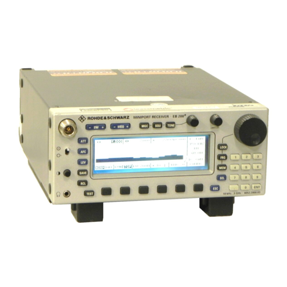
EB200 Manual Operation 3 Operation 3.1 Description of the front panel Fig. 3-1: Front view Table 3-1: Controls and displays Item. Designation Function N-connector Antenna connection Bandwidth selection Selection of modulation mode FM, AM, PULSE, CW, USB, LSB or IQ Switches MGC function on or off. - Page 16 EB200 Manual Operation Item. Designation Function Display The display is subdivided into the working area and the softkey area and also into areas for direct functions, VAR pot functions, menu names, spinwheel functions Display and the selector (see " " on page 5) Softkeys Function depends on the menu status.
-
Page 17: Overall View Of Operating Elements And Menus
EB200 Manual Operation 3.2 Overall view of operating elements and menus Selects modulation mode FM, AM, PULSE, CW, USB, LSB, IQ Selects IF bandwidth Selects the manual gain control, squelch and tone function; values can be varied with the VAR potentiometer... -
Page 18: Mscan
EB200 Manual Operation MAIN menu M-SCAN (scan with stored values) RUN (starts scan) STOP(stops scan) SUPP (suppresses memory location) CONFIG (selects configuration menu) RUN (starts scan) ACTIVATE (activates memory location) SUPP (suppresses memory location) DELETE (clears current memory location or all memory locations) RX <->... - Page 19 EB200 Manual Operation DISPLAY (menu display modes) DEFAULT (selection of display setting) IF-PAN (IF panorama display) LEVEL (level display as bar or numerically) TONE (signal tone whose pitch depends on the signal level) CONFIG (setting the selected display mode) MORE (more menus)
-
Page 20: Display
EB200 Manual Operation 3.3 Display Fig. 3-2: Display Working area The working area can be expanded for certain, display-intensive menus or for panorama displays, but the direct-function fields, the VAR potentiometer functions and the display area for the spinwheel functions will be partially or completely obscured. -
Page 21: Frequency Display
EB200 Manual Operation Menu names On the right-hand side of the screen above the softkey bar, there is a window for the name or designation of the menu that is currently activated. The menu name always corresponds to the designation of the softkey that was used to activate the menu. If you are in a second or third level submenu, the names of the menus above are displayed above the menu name window. -
Page 22: Level Display
EB200 Manual Operation 3.3.2 Level display Level-bar display The top bar shows the signal level with 1 dB resolution. The lower bar shows the squelch threshold with 1 dB resolution. The lowest value of the level scale is configurable with the parameter LOW BAR LIMIT in steps of –30, -10 and 10 dBµV. -
Page 23: Offset Display, Tuning
EB200 Manual Operation Numeric level display The numeric level value is also displayed in different sizes. The value is displayed in dBµV with a decimal point (resolution 0.1 dB). At bandwidths ≤ 0.6 kHz, also level values ≤ -20 dB µ V are displayed. -
Page 24: If Spectrum (Option)
EB200 Manual Operation 3.3.4 IF spectrum (option) The width of the IF panorama display can be adjusted by the SPAN parameter. The setting range is 150 Hz up to 1000 kHz in 17 steps. Additionally the width of the IF-panorama display can be set to COUPLED. -
Page 25: Symbols
EB200 Manual Operation 3.3.6 Symbols Signal > threshold display The lamp symbol only appears above the menu name in the working area if the receive signal threshold is exceeded. Overdrive display This symbol flashes when the IF section is overdriven. Level measurement is possible without overdriving to approx. -
Page 26: Status And Error Messages
EB200 Manual Operation Memory location status display (information to the right of the memory location number) FULL refers to the memory location filled with receiver parameters NOT SET corresponds to ’suppressed’, SUPP softkey in the M-SCAN menu corresponds to ’activated’, ACTIVATE softkey in the M-SCAN - CONFIG menu 3.3.7 Status and error messages... -
Page 27: Direct Keys
EB200 Manual Operation 3.4 Direct keys Note: When you press the keys MOD, BW, MGC, SQU, TONE, ATT, AFC and LEV once, the next selection is activated. The displayed window shows the already changed setting. Thus the unit can be operated blindfold. -
Page 28: Mgc-Squ-Tone Keys And The Var Potentiometer
EB200 Manual Operation 3.4.3 MGC-SQU-TONE keys and the VAR potentiometer All three functions can be turned on or off. In the ON state, a setting value can be assigned. This value can be adjusted with the VAR potentiometer (on the left next to the volume control). -
Page 29: Att Key (Attenuator)
EB200 Manual Operation TONE key Turning the tone function on or off The TONE status is presented below the TONE key on the display. If TONE is turned off, TONE OFF is displayed. If TONE is turned on, TONE is displayed with a value between -14 and 94 (tone reference value). -
Page 30: Afc Key (Automatic Frequency Control)
EB200 Manual Operation 3.4.5 AFC key (automatic frequency control) Turning the AFC function on or off When the AFC is on, the lettering is in inverse video. After pressing the AFC key (automatic frequency control) the frequency of the receiver is followed up automatically to a changing signal frequency. -
Page 31: Decimal Keypad
EB200 Manual Operation 3.5 Decimal keypad Keys 0 to 9, decimal point and Enter key (ENT) The effect of pressing the ENT key is to store the value in the editor as the currently selected parameter. As there is no CLR key and no +/- key, these functions are implemented as softkeys in the temporary editor (see "POP-UP editor"... -
Page 32: Memory Functions
EB200 Manual Operation 3.8 Memory functions If you want to modify the contents of a memory location, the contents of the memory location must be transferred to the receiver with RCL (see "SAVE and RCL keys (memory functions)" on page 16), modified with the hardkeys or softkeys in RX-CONF (see "RX-CONF (receiver configuration)"... -
Page 33: Relationship Between The Frq, Mem, Sel And Lock Keys
"SENSITIVITY OUT OF RANGE" is output. 3.11 ON/OFF switch The toggle switch turns the operating voltage to the EB200, which is generated by a DC/DC converter, on or off. The backlit LCD indicates when the EB200 is ON. -
Page 34: Volume Potentiometer
EB200 Manual Operation 3.14 Volume potentiometer The digital potentiometer which has 24 switch positions per turn is used to vary the AF level. The levels at the headphone connector, the integral loudspeaker and at the regulated AF-output on the rear panel can be adjusted. -
Page 35: Pop-Up Editor
EB200 Manual Operation 3.16 POP-UP editor When one of the decimal keys (0 to 9 and the decimal point) is pressed for the first time, a temporary EDIT window is displayed above the softkey bar; all numerical entries are shown in this window. -
Page 36: Softkeys In The Editor Window
EB200 Manual Operation 3.16.1 Softkeys in the editor window MHZ softkey The basic unit of all frequencies is always MHz. From that this softkey has the same importance as the ENT key does. KHZ softkey The principal units in all menus are always MHz. To make kHz entries easier, a KHZ softkey has also been provided. -
Page 37: Changing Configuration Parameters
‘.’ corresponds to the infinity sign (for example with the parameter CYCLES) As the EB200 does not have any CURSOR keys, toggle and increment or decrement functions are implemented by means of the spinwheel. In order to be able to also enter non-numerical parameters when the spinwheel is locked, the numbers 0, 1, 2, etc. -
Page 38: Softkey Menus
The name of the menu will be found in a window above the SETUP softkeys. POWER-ON menu This menu display is shown for 30 s whenever the EB200 is turned on. Note: If the processor is supplied with expansion-RAM then will be displayed instead of As soon as keys or knobs are used, the MAIN menu appears. -
Page 39: M-Scan
Operation 3.18.1 M-SCAN The EB200 contains 1000 definable memory locations. Every memory location contains the essential receiver parameters such as frequency, modulation method, bandwidth, squelch, antenna number, attenuation and AFC. In the operation mode Memory Scan the stored and activated channels are scanned in a periodical way on occupancy . -
Page 40: M-Scan - Config
EB200 Manual Operation 3.18.1.1 M-SCAN - CONFIG This menu is obtained by pressing the CONF softkey in the M-SCAN menu. Softkeys RUN-: Scan starts from current memory location number, decreasing frequency, menu change after M-SCAN RUN+: Scan starts from the current memory location number, increasing frequency, menu... - Page 41 T_DWELL in a periodical way. The signal bit corresponds to the signal on pin 6 of the audio connector X8 at the rear panel of the EB200 and indicates whether the instantaneous signal level is above the squelch value. If the signal bit disappears, the hold time is activated. After the hold time has elapsed the scanning will continue with the next frequency.
-
Page 42: M-Scan - Config - Delete
EB200 Manual Operation 3.18.1.2 M-SCAN - CONFIG - DELETE This menu can be obtained by pressing the DELETE softkey in the M-SCAN - CONFIG menu. A window with commands for deleting memory location contents opens. Softkeys Delete all CURRENT Delete current memory location (select with the MEM key, then choose the memory... -
Page 43: F-Scan
EB200 Manual Operation 3.18.2 F-SCAN In the operation mode F-SCAN a frequency range which is defined with start frequency and stop frequency is monitored during scanning. To the current frequency the step frequency is added or subtracted and the resulting frequency set. For every set frequency the level is measured. On the occupied channels, that is, channels with a signal bigger than the set squelch threshold, the scanning stops for a definable time. -
Page 44: F-Scan - Config
EB200 Manual Operation 3.18.2.1 F-SCAN - CONFIG This menu is obtained by pressing the CONFIG softkey in the F-SCAN menu. Softkeys RUN- Scan starts from the current frequency or the stop frequency with decreasing frequency. There is a menu change after F-SCAN RUN+ Scan starts from the current frequency or the start frequency with increasing frequency. -
Page 45: F-Scan - Config - Supp
EB200 Manual Operation 3.18.2.2 F-SCAN - CONFIG - SUPP This menu is obtained by pressing the SUPP softkey in the F-SCAN-CONFIG menu. Only one line of the table with the suppressed frequency range is ever edited. Configuration parameters INDEX Current line number of the suppress table:... -
Page 46: D-Scan (Option)
EB200 Manual Operation 3.18.3 D-SCAN (option) This menu is obtained by pressing the D-SCAN softkey in the MAIN menu. The marker position is highlighted through a dashed line. To the right next to the marker, the level measured at the marker position is represented in a tracking window. Thus individual signals can be measured for level and frequency. -
Page 47: D-Scan Config
Ethernet interface by means of TCP to an application. This is the default setting after the switch-on of the EB200 and corresponds to the DSCan speed corresponding to the firmware versions up to V01.07. -
Page 48: D-Scan Cycle
EB200 Manual Operation CYCLES Number of sweeps 1 to 1000 / infinite REF LEVEL The reference level determines the largest level value to be represented. It can be set in the range of 0 to 110 dBµV in steps of 10 dB. Also intermediate values can be set via remote control or by means of direct number input. -
Page 49: Spectrum Display Norm With Squelch On
EB200 Manual Operation 3.18.3.4 Spectrum display NORM with squelch on When the squelch is set on, the squelch line is displayed at a y-position corresponding to the squelch value. Furthermore the function of the marker-to-peak softkey is extended so that every time the softkey is pressed, the mark jumps to the next signal maximum above the squelch line, one after another. -
Page 50: Spectrum Display With Bw Zoom
EB200 Manual Operation 3.18.3.7 Spectrum display with BW ZOOM For a more accurate analysis of single signals the BW ZOOM can be set on. In this mode there is a firm rule that one pixel on the y-axis equals one channel and thus the frequency range of half the IF bandwidth. -
Page 51: Ant (Antenna)
FREQ or ANT + CTRL (selection by spinwheel). At the rear panel of the EB200 on the two 8-bit ports can either the frequency information in BCD four- digit (1 MHz, 10 MHz, 100 MHz and 1 GHz) or the antenna number with two digits on the one port and the CTRL byte in binary form on the other port be output. -
Page 52: Measure (Configuration Of Measuring Time Parameters)
EB200 Manual Operation 3.18.4.2 MEASURE (configuration of measuring time parameters) (See also Annex E (Measuring Functions)) Softkeys The softkeys indicate in each case the active state inversely. CONTIN continuous measurement of all values PERIODIC periodic measurement of all values with measuring time... -
Page 53: Af Configuration
In the position TONE WITH AF, the audio frequency is audible additionally to the signal tone. BALANCE: Between left and right audio channel at the headphone connector The bar can be shifted to the left or to the right by spinwheel. The EB200 is not equipped for stereo reception. 4052.2000.02 3.39... -
Page 54: System Menu
EB200 Manual Operation 3.18.4.4 SYSTEM menu This menu is obtained by pressing the SYSTEM softkey in the RX-CONF menu. Display of software version and series number MAIN CPU Main controller IF DSP DSP for the IF-section IF PAN DSP DSP for IF-panorama (option) - Page 55 EB200 Manual Operation PROTECT password entry This menu is obtained by pressing the PROTECT softkey in the SYSTEM menu. If the password status is ON, the user is asked to enter the password when the unit is turned on. Display parameter...
-
Page 56: Annex G (Coverage Measurement)
See also Annex H (Field Strength Measurement). Softkey INSTALL Branches to the SW_OPT menu Activating a SW option by entering an 8-digit code number Note: When ordering a software option at a later stage the serial number of the EB200 is to be indicated. 4052.2000.02 3.42... -
Page 57: Test
EB200 Manual Operation 3.18.4.5 TEST This menu is obtained by pressing the TEST softkey in the RX-CONF menu Note: If the processor is equipped with the expansion RAM, instead of is displayed. It the EB 200 is equipped with a new IF section (produced as from 4. 2000), IF SECTION.2 appears on the display. -
Page 58: Display
EB200 Manual Operation Configuration parameters TEST POINT OFF or selection of a test point of the subassemblies. When a test point is selected, a permanent display windows opens. The window contains the name of the subassembly, the selected test point, the current voltage in mV and, if necessary, an arrow that indicates whether is above or below the limit. -
Page 59: Display (Display Variants)
EB200 Manual Operation 3.18.5 DISPLAY (display variants) This menu is obtained by pressing the DISPLAY softkey in the MAIN menu. With this menu, you can select quickly from a number of display variants. This permits parameters important for a particular task to be put to the foreground. - Page 60 EB200 Manual Operation DISPLAY DEFAULT with TUNING AID: IF PAN This menu is obtained by configuring, in the Default Config Menu, the LOW BAR LIMIT to IF PAN. 4052.2000.02 3.46...
-
Page 61: If-Pan (If Panorama)
3.18.5.1 IF-PAN (IF panorama) This menu is obtained by pressing the IF PAN softkey in the DISPLAY menu, provided the optional hardware EB200 SU (IF panorama) is installed. IF-PAN (IF panorama) - CONFIG This menu is obtained by pressing the CONFIG softkey in the IF-PAN menu. - Page 62 EB200 Manual Operation Softkeys Starts the MIN-Hold process. Every time this key is pressed the MIN-Hold process is restarted. Starts the MAX-Hold process. Every time this key is pressed the MAX-Hold process is restarted. Starts averaging according to selection. Each time this key is pressed the averaging function AVG is started anew.
-
Page 63: Level Bar (Level Measurement)
EB200 Manual Operation 3.18.5.2 LEVEL BAR (level measurement) This menu is obtained by pressing the LEVEL softkey in the DISPLAY menu. Just as the large level bar display, this window also shows the antenna which is currently activated, and the numerical level indication. -
Page 64: Tone (Signal Tone; Pitch Depends On The Signal Level)
EB200 Manual Operation 3.18.5.3 TONE (signal tone; pitch depends on the signal level) The menu is obtained by pressing the TONE softkey in the DISPLAY menu. This menu shows the expanded level bar display (see "Level display" on page 8). -
Page 65: Frq (Frequency)
EB200 Manual Operation 3.18.5.4 FRQ (frequency) This menu is obtained by pressing the FRQ softkey in the DISPLAY-MORE menu. Here the numerical level value is shown in addition to the large frequency display. For reasons of space, the position of the overdrive indicator differs from that in the other menus. -
Page 66: Keys
EB200 Manual Operation 3.18.6.1 KEYS This menu is obtained by pressing the KEYS softkey in the SETUP menu. Configuration of the spinwheel functions and the key characteristics. The selection is made with SEL, the spinwheel and the editor (number block). -
Page 67: Message
EB200 Manual Operation 3.18.6.2 MESSAGE Configuration of the acoustic and optical messages to the operator. This menu is obtained by pressing the MESSAGE softkey in the SETUP menu. Error messages MESSAGE DISPLAY OFF, display duration for error messages: 1, 2, 3, 4, 5 sec and infinite (see "Status and error messages"... -
Page 68: Power
This menu is obtained by pressing the POWER softkey in the SETUP menu. Configuration parameters SOURCE: Power source: DC X1 DC power supply or charger BATTERY PACK EB200 Battery Pack DC X2 Battery belt BATTERY1 / 2: Status of battery 1 / 2: NOT EQUIPPED NOT IN USE... -
Page 69: Aux
BCD (1 MHz, 10 MHz, 100 MHz and 1 GHz) or the two-digit antenna number at one port and the binary CTRL byte at the other. The connector X8 is located at the rear panel of EB200. For its pin assignment refer to the interface description contained in the manual. -
Page 70: Remote (Remote Control)
The appropriate window for the fitted option opens automatically. After a cold start, the Rohde & Schwarz default values are always used. LAN control interface (option) Configuration parameters IP ADDRESS: Network ident of EB200 PORT: Remote control port SUBNETMASK: Mask for a subnet... -
Page 71: Operating Modes
In this operating mode, TCP/IP with the Point to Point Protocol is activated for remote control. Configuration parameters BAUD RATE: Baud rate: 50 to 115 k with many intermediate values IP ADDRESS: Network ident of EB200 PORT: Remote control port Softkeys APPLY... - Page 72 EB200 Manual Operation RS 232 standard Configuration parameters BAUD RATE: Baud rate: 50 to 115 k with many intermediate values FRAME: 7 or 8 data bits, 1 or 2 stop bits PARITY: NO, ODD or EVEN HANDSHAKE: NO, XON-XOFF or RTS-CTS...
-
Page 73: Operating Elements
EB200 Manual Operation Inhibiting the operating elements at remote control The message in the softkey area of the display is switched on and off by the remote control command SYSTem:KLOCk ON|OFF . At the same time the keyboard and the spinwheel are disabled. Now only pure remote-control operation is possible. - Page 74 Operation The 3 line shows the essential parameters of the remote-control interface: Remote-control option: LAN LAN ADDRESS: Network ident of EB200 Remote-control option: RS232 in PPP mode RS232 PPP: Baud rate: 50 to 115 k with many intermediate values ADDRESS:...
-
Page 75: Remote Control
EB200. Just enter the command “ping <IP-Address>“ (eg “ping 192.0.0.2“) in the DOS box. 5. Commands can be sent to and messages can be received from the EB200 by means of a Telnet application which is started and configured with the interface parameters of EB200. -
Page 76: Remote Control Via Lan Interface (Option)
2. On the controller TCP/IP must be installed. The network adapter card must be set to half-duplex. 3. When the EB200 is operated within a network, is must be set to a network-compatible IP address. The network administrator will be able to provide further information on this. Also see Annex D. -
Page 77: Structure And Syntax Of The Device Messages
EB200 Manual Remote control 4.4 Structure and syntax of the device messages 4.4.1 SCPI introduction SCPI (Standard Commands for Programmable Devices) describes a standard command set for programming devices, irrespective of the type of device or manufacturer. The goal of the SCPI consortium is to standardize the device-specific commands to a large extent. -
Page 78: Fig. 4-1: Tree Structure Of The Scpi Command System Using The Sense System By Way Of An Example
EB200 Manual Remote control Device-specific commands Hierarchy: Device-specific commands are of hierarchical structure (see Fig. 4-1). The different levels are represented by combined headers. Headers of the highest level (root level) have only one keyword. This keyword denotes a complete command system. -
Page 79: Remote Control
EB200 Manual Remote control Some keywords occur at several levels within one command system. Their effect depends on the structure of the command, that is to say, at which position in the header of a command they are inserted. Example: OUTPut:OUTPut:SQUelch:STATe ON This command contains the keyword STATe at the third command level. - Page 80 EB200 Manual Remote control Note: The short form is marked by upper-case letters, the long form corresponds to the complete word. Upper-case and lower-case notation only serve the above purpose, the device itself does not make any difference between upper- and lower-case letters.
-
Page 81: Structure Of A Command Line
EB200 Manual Remote control 4.4.3 Structure of a command line Several commands in a line are separated by a semicolon ";". If the next command belongs to a different command system, the semicolon is followed by a colon. Example: SENSe:FREQuency:STARt MINimum;:OUTPut:FILTer:LPAS:STATe ON This command line contains two commands. -
Page 82: Responses To Queries
EB200 Manual Remote control 4.4.4 Responses to queries A query is defined for each setting command unless explicitly specified otherwise. It is formed by adding a question mark to the associated setting command. According to SCPI, the responses to queries are partly subject to stricter rules than in standard IEEE 488.2. -
Page 83: Parameters
EB200 Manual Remote control 4.4.5 Parameters Most commands require a parameter to be specified. The parameters must be separated from the header by a "white space". Permissible parameters are numerical values, Boolean parameters, text, character strings, block data and expressions. The type of parameter required for the respective command and the permissible range of values are specified in the command description (see "Description of commands"... - Page 84 EB200 Manual Remote control INFinity stands for + ∞ . For queries the numerical value 9,9E37 is output. With MSCAN, FSCAN or DSCAN, the INF value 9,9E37 is entered in the result buffers MTRACE and ITRACE to mark the end of range.
-
Page 85: Data Formats
EB200 Manual Remote control Block data Block data (Definite Length Block) are a transmission format which is suitable for the transmission of large amounts of data. A command using a block data parameter has the following structure: Example: HEADer:HEADer #45168xxxxxxxx ASCII character # introduces the data block. -
Page 86: Overview Of Syntax Elements
EB200 Manual Remote control 4.4.6 Overview of syntax elements The following survey offers an overview of the syntax elements. The colon separates the key words of a command. In a command line the colon after the separating semicolon marks the uppermost command level. -
Page 87: Description Of Commands
EB200 Manual Remote control 4.5 Description of commands Note: For overview of commands see tables in Annex C. 4.5.1 Notation In the following sections, all commands implemented in the device are described in detail. The notation corresponds to a large extent to that of the SCPI standards. The SCPI conformity information can be taken from the list of commands in Annex C. - Page 88 EB200 Manual Remote control Special characters A selection of keywords with an identical effect exists for some commands. These keywords are given in the same line and are separated by a vertical stroke. Only one of these keywords has to be indicated in the header of the command.
-
Page 89: Common Commands
EB200 Manual Remote control 4.5.2 Common commands The common commands are taken from the IEEE 488.2 (IEC 625-2) standard. A particular command has the same effect on different devices. The headers of these commands consist of an asterisk "*" followed by three letters. Many common commands concern the "Status reporting system" on page 127. - Page 90 EB200 Manual Remote control *IDN? IDENTIFICATION QUERY queries unit about identification. The output of the unit can be: "ROHDE&SCHWARZ,EB200,105.050/003,01.00-4052.4654.00 105050/003 is the serial number of the unit 02.72 is the version number of the firmware of the main processor (EB200P1) 4052.4654.00...
- Page 91 EB200 Manual Remote control *RST RESET sets the device to a defined default status. The default setting is indicated in the description of the commands. *SRE 0 to 255 SERVICE REQUEST ENABLE sets the service request enable register to the value indicated. Bit 6 (MSS mask bit) remains 0.
-
Page 92: Abort Subsystem
EB200 Manual ABORt subsystem 4.5.3 ABORt subsystem ABORt Stop command for measurement. This command stops an active scan. Parameters: none *RST state: none, as command is an event Example: ABORt 4052.2000.02 4.18... - Page 93 EB200 Manual CALCulate subsystem 4.5.4 CALCulate subsystem CALCulate :IFPan :AVERage :TIME <numeric_value> Setting of the averaging time for the SCALar averaging procedure Parameter: averaging time in steps of 0, 100, 500 ms <numeric_value> Remark: For MAIN CPU versions > 1.18 this command not only has effect on the averaging time of the IF- panorama but also on the global measuring time.
-
Page 94: Calculate Subsystem
EB200 Manual CALCulate subsystem :TYPE MINimum|MAXimum|SCALar|OFF Setting of the averaging procedure for the IF-panorama data Parameters: MIN hold function is on MINimum MAX hold function is on MAXimum AVG averaging function is on SCALar Switching on the Clear Write function... - Page 95 EB200 Manual CALCulate subsystem :MARKer:MAXimum[:PEAK] Centering of the IF-panorama spectrum to the absolute level maximum Parameters: none Example: CALCulate:IFPan:MARKer:MAXimum :MARKer:MAXimum:LEFT Centering of the IF-panorama spectrum to the next relative level maximum left of the marker when the squelch is off. When it is on the center frequency is set to the next level maximum to the left which is above the squelch line.
- Page 96 EB200 Manual CALCulate subsystem :DSCan :AVERage :TYPE MAXimum|OFF Setting of the display mode of the DSCan spectrum Parameters: indication of maximum values MAXimum indication of current values *RST state: Example: CALCulate:DSCan:AVERage:TYPE MAXimum :TYPE? Query of the display mode of the DSCan spectrum...
- Page 97 EB200 Manual CALCulate subsystem :MARKer:MAXimum[:PEAK] The frequency marker jumps to the absolute level maximum in the DSCan spectrum. Parameters: none Example: CALCulate:DSCan:MARKer:MAXimum :MARKer:MAXimum:NEXT The frequency marker jumps to the next relative level maximum right of the marker within the DSCan spectrum when the squelch is off.
-
Page 98: Diagnostic Subsystem
(EB200P1) DSP IF Section (EB200Z1) DSP IF Panorama (EB200SU) Front Panel Control Unit (EB200F1) DC/DC Converter (EB200 DC) Result: Software version and identification number of software in format Vxx.yy-aaaa.bbbb.cc (also see *IDN?) Note: The query with <numeric suffix> = 5 (DC/DC converter controller) brings up only the version number without the stock number. - Page 99 EB200 Manual DIAGnostic subsystem :MONitor? <module> Output of test point information of one or all modules recognized. Parameters: information relating to module to be queried: <module > Processor Preselection Standard frontend 1 Standard frontend 2 IF section DC/DC converter IF panorama...
- Page 100 EB200 Manual DIAGnostic subsystem [:MEASure]:TPOint[<numeric_suffix>]? <module> Output of the voltage at a test point on a module. With <numeric_suffix> one of the test points (1 to 8) on the module is selected. Parameter: Indication of module to be queried <module>...
-
Page 101: Display Subsystem
EB200 Manual DISPlay subsystem 4.5.6 DISPlay subsystem DISPlay :BRIGhtness <numeric_value>|MINimum|MAXimum Controls the brightness of the display backlighting Parameters: brightness of backlighting from 0 to 1 <numeric_value> 0 = backlighting off 1 = full backlighting backlighting off|full backlighting MINimum|MAXimum Remark: The brightness can be set in 7 discrete steps. Intermediate values are therefore rounded to the nearest discrete value. - Page 102 EB200 Manual DISPlay subsystem :BRIGhtness:DWELl <numeric_value>|MINimum|MAXimum|INFinity Controls the switch-on time of display backlighting. When the switch-on time has elapsed, the backlighting is switched off. The switch-on time is started again after every keystroke. Parameter: switch-on time in seconds (it is rounded to values <numeric_value>...
- Page 103 EB200 Manual DISPlay subsystem :CMAP:DEFault Selection of normal display representation Parameters: none *RST state: NORMal Example: DISPlay:CMAP:DEFAULT :CMAP NORMal|INVerted Selection of normal or inverted display representation Parameters: background white, letters and lines black NORMal background black, letters and lines white...
- Page 104 CONTROLLED BY REMOTE is displayed on the front panel in the "disable" state. The string can be configured by means of the DISPLAY:ENABLe:LABel command. This command is advantageous if, in systems, EB200 is exclusively controlled by Remote. When the front-panel controls are switched off, additional computing power becomes available in the processor and time-critical operations (scans, transmission of large volumes of data) run much more quickly.
- Page 105 EB200 Manual DISPlay subsystem :ENABle:LABel<string> Entry of a user-defined information string displayed on the front panel in the DISPlay:ENABle OFF state. The user is informed why the system under remote control has switched the display off and why manual control is currently disabled.
- Page 106 EB200 Manual DISPlay subsystem :MENU[:NAME] <menu_name> Selection of a specific display representation from the given list. Parameters: DEFAULT display of frequency, offset and level <menu_name> IFPAN starts the option EB200SU (IF panorama) and preferably the display of the IF panorama data...
-
Page 107: Format Subsystem
EB200 Manual FORMat subsystem 4.5.7 FORMat subsystem FORMat :BORDer NORMal|SWAPped Specifies whether binary data is first to be transferred with low or high byte. Note: This command only has an effect upon the trace data. For UDP data there is a separate setting possibility, described in Annex F (Datagram Communication). - Page 108 EB200 Manual FORMat subsystem [:DATA]? Query of output format of the above-mentioned queries Parameters: none Result: ASC, PACK Example: FORMat? -> PACK :DIAGnostic:MONitor ASCii|PACKed Sets the output format for the query DIAGnostic:MONitor?. Parameters: output in ASCII format ASCii output in internal binary data format...
- Page 109 EB200 Manual FORMat subsystem :MEMory ASCii|PACKed Specifies the output format of the queries MEMory:CONTents? Parameters: output in ASCII format ASCii output in internal binary data format PACKed *RST state: ASCii Example: FORMat:MEMory PACKed :MEMory? Query of output format of above-mentioned queries...
- Page 110 EB200 Manual FORMat subsystem :SREGister? Query with which data format the above-mentioned queries are carried out Parameters: none Result: ASC, BIN, HEX Example: FORMat:SREGister? -> HEX 4052.2000.02 4.36...
-
Page 111: Initiate Subsystem
EB200 Manual INITiate subsystem 4.5.8 INITiate subsystem INITiate [:IMMediate] Request to provide a current measured value. Also serves as start command for the different SCAN modes. If SENSe:FREQuency:MODE set to CW|FIXed, then with each INITiate command a measurement is carried out, the result possibly being stored in the MTRACE or ITRACE. -
Page 112: Input Subsystem
EB200 Manual INPut subsystem 4.5.9 INPut subsystem INPut :ATTenuation :AUTO <Boolean> Setting attenuation so that the best dynamic range is obtained; explicit switch on/off of attenuator sets AUTO to OFF Parameters: attenuation is coupled to input-signal strength attenuation is manually switched... -
Page 113: Setting Parameters
EB200 Manual INPut subsystem :STATe? Query of the input attenuator setting Parameters: none Result: Attenuator on Attenuator off Example: INPut:ATTenuation:STATe? -> 1 4052.2000.02 4.39... -
Page 114: Measure Subsystem
EB200 Manual MEASure subsystem 4.5.10 MEASure subsystem (See also Annex E (Measuring Functions)) MEASure :MODE CONTinuous|PERiodic Setting of continuous or periodic measuring mode In the PERiodic measurement mode all detectors are discharged after the measuring time has elapsed, and the next measurement is started. Only the individual measured values per measuring period are displayed. -
Page 115: Measuring Time
EB200 Manual MEASure subsystem :TIME <numeric_value>|MINimum|MAXimum|DEFault Setting of the measuring time for all measuring functions The set measuring time also has an impact on the averaging time of the IF-panorama data. Note: As from MAIN CPU version 2.31, the version of the DSP software (IF DSP) indicates what kind of DDC is fitted in the IF section. -
Page 116: Memory Subsystem
MEMory subsystem 4.5.11 MEMory subsystem This subsystem contains all the functions necessary to operate the EB200 memory locations. The memory locations are addressed with the text (see "Parameters" on page 9) MEM0 to MEM999 (memory location 0 to memory location 999). Some commands allow the receiver (data set of receiver settings) to be addressed by Character Data RX, the currently set memory location by CURRENT and the next free memory location by NEXT . - Page 117 EB200 Manual MEMory subsystem :CONTents <name>,<mem_paras>|<packed_struct> Loading a memory location As an alternative to the parameter field (<mem_paras>) a <Definite Length Block> can be transferred with binary data. Parameters: MEM0 to MEM999 | RX | CURRENT | NEXT <name> <mem_paras>...
- Page 118 EB200 Manual MEMory subsystem :CONTents? <name>|RX Query of contents of memory location Parameters: MEM0 to MEM999 | RX | CURRENT <name> Result: Depending on the setting by the command FORMat:MEMory either an ASCII data set or a binary data set is output: The ASCII data set has the following structure: <F>,<THR>,<DEM>,<BW>,<ANT>,<ATT>,<ATTA>,<SQUC>,<AFC>,<ACT>...
- Page 119 EB200 Manual MEMory subsystem :MPAR? <name> Query of memory-location parameter <ACT> Parameters: MEM0 to MEM999 | CURRENT <name> Result: set/reset for scan (1/0) <ACT> Example: MEMory:CONTents:MPAR? MEM1 -> 0 :EXCHange <name1>, <name2> Exchange of contents of two memory locations Parameters: MEM0 to MEM999 | RX | CURRENT <name1>...
-
Page 120: Output Subsystem
EB200 Manual OUTPut subsystem 4.5.12 OUTPut subsystem OUTPut :AUXMode FREQuency|ANTCtrl The AUX mode switch determines whether the frequency in BCD or the antenna number in BCD and the CTRL byte should be output at the rear-panel AUX connector X8. The FREQuency setting is to be used together with DF Unit EBD190. - Page 121 EB200 Manual OUTPut subsystem :BITAux [<numeric_suffix>] [:STATe] <Boolean> Sets the AUX bits at the rear panel <numeric_suffix> byte 1 corresponds to CTRL1 at X8.8’AUX’ byte 2 corresponds to CTRL2 at X8.27’AUX’ byte 3 corresponds to CTRL3 at X8.9’AUX’ byte 4 corresponds to CTRL4 at X8.28’AUX’...
- Page 122 EB200 Manual OUTPut subsystem :BYTAux [:STATe] <numeric_value> Sets the 8 AUX bits by a single byte command Parameters: value of the AUX bytes (0 to 255, #H00 to #HFF or #B0 <numeric_value> to #B11111111) *RST state: Example: OUTPut : BYTAux 7 .
- Page 123 EB200 Manual OUTPut subsystem [:STATe]? Query of squelch setting Parameters: none Result: squelch on squelch off State: OUTPut:SQUelch? -> 1 . :CONTrol MEMory|NONE Selection of the source for the operating state after switching the unit on, when reading the memory locations by the MEMory:COPY command, when using the RCL key or when running memory scan.
- Page 124 EB200 Manual OUTPut subsystem :THReshold [:UPPer] <numeric_value>|UP|DOWN|MINimum|MAXimum Setting of squelch threshold Parameters: squelch threshold in dBuV <numeric_value> increase|decrease of squelch threshold by the value set with the UP|DOWN command OUTPut:SQUelch:THReshold[:UPPer]: STEP[:INCRement]. setting the lowest/highest squelch threshold MINimum|MAXimum *RST state: 10 dBuV...
- Page 125 EB200 Manual OUTPut subsystem [:INCRement]? [MINimum|MAXimum] Query of stepwidth Parameters: none query of currently set stepwidth query of smallest|largest stepwidth MINimum|MAXimum Result: Stepwidth of squelch threshold in dB µ V Example: OUTP:SQU:THR:STEP? -> 10 :TONE [:STATe] <Boolean> Switch on/off of level tone function. With level tone function switched on a tone is output depending on the level magnitude.
-
Page 126: Audio
EB200 Manual OUTPut subsystem :CONTrol ONLY|WITHaf It can be selected whether, in the TONE mode, only the level tone or also the AF is output via the audio channel. Parameters: level tone and AF is output. WITHaf only level tone is output. - Page 127 EB200 Manual OUTPut subsystem :THReshold? [MINimum|MAXimum] Query of level tone reference threshold Parameters: none query of current level tone reference threshold query of lowest/highest level tone reference threshold MINimum|MAXimum Result: Level tone reference threshold in dBuV Example: OUTPut:TONE:THReshold? MIN -> 6 :STEP [:INCRement] <numeric_value>|MINimum|MAXimum...
-
Page 128: Route Subsystem
EB200 Manual ROUTe subsystem 4.5.13 ROUTe subsystem ROUTe :CLOSe <channel_list> Selection of an antenna. Prior to this the old antenna must be switched off with ROUTe:OPEN:ALL (see ROUTe:SELect). Error message: If more than one antenna is to be selected an execution error -221,"Settings conflict" is generated. - Page 129 EB200 Manual ROUTe subsystem OPEN :ALL Select no antenna (antenna number 0 is set) Parameters: none *RST state: none since command is an event Example: ROUTe:OPEN:ALL :PATH :CATalog? Request of a list with currently defined antenna names If the option EB200FS (Field Strength Measurement) is fitted, specific names are assigned to antenna numbers 1 to 5 (see example below).
- Page 130 EB200 Manual ROUTe subsystem [:DEFine]? <path_name> Query of antenna number associated with specified antenna name Parameters: <path_name> see ROUTe:PATH:DEFine Error message: If the <path_name> could not be found in the list of names, an execution error -292, "Referenced name does not exist" will be generated.
- Page 131 EB200 Manual ROUTe subsystem SELect <channel_list>|UP|DOWN|MINimum|MAXimum Equivalent to the combination: ROUTe:OPEN:ALL ROUTe:CLOSe <channel_list> Parameters: allowed to contain only one number (0 to 99) <channel_list> transition to next/previous antenna UP|DOWN setting of antenna with smallest/largest number MINimum|MAXimum *RST state: See ROUTe:CLOSe...
-
Page 132: Sense Subsystem
EB200 Manual SENSe subsystem BANDwidth 4.5.14 SENSe Subsystem [SENSe] :BANDwidth|BWIDth [:RESolution] <numeric_value>|UP|DOWN|MINimum|MAXimum Selection of bandwidth Parameters: value of bandwidth <numeric_value> to next|previous bandwidth UP|DOWN setting the narrowest|widest bandwidth MINimum|MAXimum *RST state: 100 kHz or the nearest bandwidth Example: BANDwidth 2.4 kHz... - Page 133 EB200 Manual SENSe subsystem DATA? :DATA? [<data_handle>] Query of the current measured values of active sensor functions. When only the command SENSe:DATA? is used to query measured values, the measured values reported back may be as old as 200 ms. For display on the unit measured values are captured every 200 ms and put into a buffer.
- Page 134 EB200 Manual SENSe subsystem DATA? Result: Level in dB µ V, offset in Hz, field strength in dB µ V/m The output format will be generated with the command FORMat:DATA according to the setting: normal ASCII output ASCii PACKed <Definite Length Block>: level in 1/10 dB µ...
- Page 135 EB200 Manual SENSe subsystem DEModulation :DEModulation AM|FM| PULSe|A1|CW|LSB|USB|IQ|A0 Switchover of type of demodulation Note: For SSB demodulation (CW, LSB and USB,) the frequency stepwidth is set to 1 Hz.. Error message: If the set bandwidth exceeds 9 kHz at CW, LSB and USB, an error -221,"Settings conflict" will be generated if one of the SSB operating modes is to be switched on.
- Page 136 EB200 Manual SENSe sbsystem DETector :DETector . [:FUNCtion] POSitive|PAVerage|FAST Switching over the level-measuring process Parameters: measuring the peak value (PEAK) POSitive measuring the average value (AVG) PAVerage measuring the current value (FAST) FAST *RST state: PAVerage Example: DETector POSitive . [FUNCtion]?
- Page 137 EB200 Manual SENSe subsystem DSCan :DSCan :COUNt <numeric_value>|MINimum|MAXimum|INFinity Statement of number of DSCan runs Parameters: number of runs <numeric_value> minimum/maximum number MINimum|MAXimum infinite number INFinity *RST state: INFinity Example: DSCan:COUNt 100 :COUNt? [MINimum|MAXimum] Query of number of DSCan runs Parameters:...
- Page 138 EB200 Manual SENSe subsystem FREQuency :FREQuency :AFC <Boolean> Switch on/off the AFC function. Parameters: AFC function on AFC function off *RST state: Example: SENSe:FREQuency:AFC ON :AFC? Query of AFC function Parameters: none Result: AFC function on AFC function off Example: SENSe:FREQuency:AFC? ->...
- Page 139 EB200 Manual SENSe subsystem FREQuency [CW|FIXed]? [MINimum|MAXimum] Query of receiver frequency Parameters: none query of current receiver frequency query of lowest|highest receiver frequency MINimum|MAXimum Result: Frequency value in Hz Example: FREQuency? -> 98500000 :DSCan If the STARt and/or STOP frequency is changed then CENTer or SPAN is adjusted.
- Page 140 EB200 Manual SENSe subsystem FREQuency :MARKer <numeric_value>|MINimum|MAXimum Sets the marker frequency of Digiscan Parameters: frequency value <numeric_value> setting min/max marker frequency MINimum | MAXimum *RST state 98.5 MHz Example: FREQuency : DSCan : MARKer 120 MHz :MARKer? [MINimum|MAXimum] Query of the marker frequency of Digiscan...
- Page 141 EB200 Manual SENSe subsystem FREQuency :RESolution:AUTO? Query of BW ZOOM mode. Parameter: none Result: BW ZOOM mode on BW ZOOM mode off Example: FREQuency:DSCan:RESolution:AUTO -> 1 :SPAN <numeric_value>|MINimum|MAXimum Sets the display range of Digiscan Corrects STARt and STOP frequency Parameters: frequency value <numeric_value>...
- Page 142 EB200 Manual SENSe subsystem FREQuency :SPEed LOW|NORMal|HIGH|MTIMe Selection of DSCan speed. The digital scan cannot be slowed down while it is running. Generated data can therefore be lost if they are not collected fast enough at the remote control interface. The maximum data throughput at the remote control interface can be fixed indirectly by setting the DSCan speed.
- Page 143 EB200 Manual SENSe subsystem FREQuency :STARt <numeric_value>|MINimum|MAXimum Sets the start frequency of Digiscan Parameters: <numeric_value> frequency value setting min/max start frequency MINimum | MAXimum *RST state: 85 MHz Example: FREQuency : DSCan : STARt 118 MHz :STARt? [MINimum|MAXimum] Query of the start frequency of Digiscan...
- Page 144 EB200 Manual SENSe subsystem FREQuency :STOP? [MINimum|MAXimum] Query of the stop frequency of Digiscan Parameters: none query of the current stop frequency query of min/max stop frequency MINimum | MAXimum Result: frequency in Hz Example: FREQuency : DSCan : STOP? → 136000000 4052.2000.02...
- Page 145 EB200 Manual SENSe subsystem FREQuency :MODE CW|FIXed|SWEep|MSCan|DSCan|FASTlevcw|LIST Changing the operating mode of the receiver. Parameters: receiver monitors a frequency (CW and FIXed have equal CW | FIXed meanings) receiver is in frequency-scan mode (see SENSe : SWEep) SWEep receiver is in memory-scan mode (see SENSe : MSCan)
-
Page 146: Ifpan
EB200 Manual SENSe subsystem FREQuency :SPAN<numeric_value>|UP|DOWN |MINimum|MAXimum Selection of frequency range with option IF panorama. The following ranges are available in addition to the IF bandwidths: 25, 50, 100, 200, 500, 1000 kHz. If a frequency range is entered it will be brought up to the next higher range. - Page 147 EB200 Manual SENSe subsystem FREQuency :STARt? [MINimum|MAXimum] Query of start frequency of a frequency scan Parameters: none query of current start frequency query of lowest|highest start frequency MINimum|MAXimum Result: Frequency in Hz Example: FREQuency:STARt? -> 118000000 :STEP [:INCRement] <numeric_value>|MINimum|MAXimum Setting the stepwidth for the command SENSe:FREQuency[:CW|FIXed] UP|DOWN Note: For SSB demodulation (CW, LSB and USB), the frequency stepwidth will be set to 1 Hz.
- Page 148 EB200 Manual SENSe subsystem FREQuency :STOP <numeric_value>|MINimum|MAXimum Setting the stop frequency of a frequency scan Parameters: frequency <numeric_value> setting the lowest|highest stop frequency MINimum|MAXimum *RST state: 650 MHz Example: FREQuency:STOP 136 MHz :STOP? [MINimum|MAXimum] Query of a stop frequency of a frequency scan...
- Page 149 EB200 Manual SENSe subsystem FUNCtion :FUNCtion If the sensor function(s) is (are) changed, the trace data set MTRACE is always deleted. :CONCurrent <Boolean> Determines whether several sensor functions can at the same time be switched or not. If CONCurrent = OFF, the command SENSe:FUNCtion[:ON] has the effect of a 1-out-of-n selection (one is switched on, the previously activated is automatically switched off).
- Page 150 EB200 Manual SENSe subsystem FUNCtion :OFF? Query of the sensor functions being switched off Parameters: none Result: List of the sensor functions being switched off. For strings see SENSe:FUNCtion[:ON] Example: FUNCtion:OFF? -> "FREQ:OFFS" :COUNt? Query of the number of sensor functions being inactive...
- Page 151 EB200 Manual SENSe subsystem FUNCtion [:ON]? Query of sensor functions being switched on Parameters: none Result: List of sensor functions switched on. If no function is active, a zero string ("") is output. The list has a specific order: 1. level measurement function 2.
- Page 152 EB200 Manual SENSe subsystem GCONtrol :GCONtrol [:FIXed|MGC] <numeric_value>|UP|DOWN|MINimum|MAXimum Setting of MGC value Parameters: gain control factor in dBµV <numeric_value> -30 dBµV = no gain control -> maximum sensitivity 110 dBµV = maximum gain control -> minimum sensitivity increase|decrease of the MGC value by the value set in the...
- Page 153 EB200 Manual SENSe subsystem GCONtrol [:INCRement]? [MINimum|MAXimum] Query of the MGC stepwidth Parameters: none query of currently set stepwidth query of smallest|largest stepwidth MINimum|MAXimum Result: MGC stepwidth in dB Example: GCONtrol:STEP? -> 10 :MODE FIXed|MGC|AUTO|AGC Type of gain control Parameters:...
- Page 154 EB200 Manual SENSe subsystem MSCan :MSCan The MSCan system controls the frequency function of the device, provided the memory scan has been activated by SENSe:FREQuency:MODE MSCan. Each scan is started by INITiate[:IMMediate]. The memory locations are placed in the MEMory subsystem and are set for query during the scan.
- Page 155 EB200 Manual SENSe subsystem MSCan [:ON]? Query of scan-control mechanism that is switched on. Parameters: none Result: A list of the scan-control mechanisms that are switched on is output. If there is nothing switched on then a zero string ("") is output.
- Page 156 EB200 Manual SENSe subsystem MSCan :COUNt <numeric_value>|MINimum|MAXimum|INFinity Information about the number of MSCans Parameters: number of scans <numeric_value> minimum|maximum number MINimum|MAXimum infinite number INFinity *RST state: INFinity Example: MSCan:COUNt 100 :COUNt? [MINimum|MAXimum] Query of number of MSCans Parameters: none query of current number of scans...
- Page 157 According to the SCPI standard, this command is used to set the dwell time per scan step, ie the time required by a step. This definition is met in EB200, if the squelch is switched off. The hold criterion is then fulfilled for each step.
- Page 158 EB200 Manual SENSe subsystem MSCan :HOLD :TIME <numeric_value>|MINimum|MAXimum Setting the hold time during signal-controlled scan continuation (T_NOSIG in MSCAN-CONFIG menu). If the signal disappears during the dwell time, the hold time is started. After completion of the hold time, the scan is continued with the next frequency even if the dwell time has not yet been completed. If the signal during the hold time exceeds the squelch threshold, the hold time is reset and the end of the dwell time or the renewed disappearance of the signal is awaited.
- Page 159 SENSe subsystem LIST :LIST Within EB200 the LIST subsystem is used to define a list of frequencies. Provided that the EB200CM SW option is fitted, in FREQuency:MODE LIST mode triggered level measurements can be carried out on up to 50 frequencies.
- Page 160 EB200 Manual SENSe subsystem ROSCillator :ROSCillator Control of reference oscillator :EXTernal :FREQuency? Query of given external reference frequency Parameters: none Result: 10000000 Example: ROSCillator:EXTernal:FREQuency? -> 10000000 [:INTernal] :FREQuency? Query of internal reference frequency Parameters: none Result: 10000000 Example: ROSCillator:FREQuency? -> 10000000...
- Page 161 EB200 Manual SENSe subsystem ROSCillator :SOURce? Query of reference oscillator to be used Parameters: none Result: internal reference oscillator external reference oscillator Example: ROSCillator:SOURce? -> EXT 4052.2000.02 4.87...
- Page 162 EB200 Manual SENSe subsystem SWEep :SWEep The SWEep system controls the frequency function of the device if the frequency scan has been activated by the SENSe:FREQuency:MODE SWEep command. Each scan is initiated by INITiate[:IMMediate]. :CONTrol :[ON] <control _function> {,<control_function>} Command for switch-on of the STOP:SIGNalfunctions.
- Page 163 EB200 Manual SENSe subsystem SWEep :OFF <control_function>{,<control_function} Switch-off of one or several scan-control functions. Parameters: see SENSe:SWEEp:CONTrol [:ON] *RST state: after *RST there is no control function running Example: SWEep:CONTrol:OFF "STOP:SIGN" :OFF ? Query of switched-off scan-control functions. Parameters: none Result: List of switched-off control functions.
- Page 164 EB200 Manual SENSe subsystem SWEep :COUNt? [MINimum|MAXimum] Query of number of sweeps Parameters: none query of current number of sweeps query of minimum|maximum sweeps MINimum|MAXimum Result: Number of sweeps; 9.9E37 is output for an infinite number Example: SWEep:COUNt? -> 100...
- Page 165 According to the SCPI standard, this command is used to set the dwell time per scan step, ie the time required by a step. This definition is met in EB200, if the squelch is switched off. The hold criterion is then fulfilled for each step.
- Page 166 EB200 Manual SENSe subsystem SWEep :TIME? [MINimum|MAXimum] Query of hold time during signal-controlled scan continuation Parameters: none query of current hold time query of lowest|highest hold time MINimum|MAXimum Result: Hold time in seconds Example: SWEep:HOLD:TIME? 0.010 :STEP<numeric_value>|MINimum|MAXimum Setting the frequency stepwidth for the frequency scan Parameters: <numeric_value>...
- Page 167 EB200 Manual SENSe subsystem SWEep :SUPPress Insert current frequency into suppress list. The range is obtained from the bandwidth according to the following formulae: SSTARTn = SENSn: FREQ - SENSn:BAND/2 SSTOPn = SENSn: FREQ + SENSn:BAND/2 The frequency pair is inserted into an empty space of the trace. Free spaces (gaps) are characterized by a frequency pair with the values 0.0.
- Page 168 EB200 Manual SENSe subsystem VOLTage :VOLTage:AC:RANGe [:UPPer]<numeric_value>UP|DOWN|MINimum|MAXimum This command is used in the DSCAN mode to set the reference level. In order to avoid overdriving of the receiver, the reference level is set to the highest expected positive signal level.
- Page 169 EB200 Manual SENSe subsystem VOLTage [:INCRement]? [MINimum|MAXimum] Query of stepwidth Parameters: none query of current stepwidth query of minimum|maximum stepwidth MINimum|MAXimum Result: Stepwidth of reference level in dBuV Example: VOLTage:AC:RANGe:STEP? -> 10 4052.2000.02 4.95...
-
Page 170: Status Subsystem
EB200 Manual STATus subsystem 4.5.15 STATus subsystem The following STATus register commands are possible according to SCPI standard: STATus :OPERation :CONDition? :ENABle <numeric_value> :ENABle? [:EVENt]? :NTRansition <numeric_value> :NTRansition? :PTRansition <numeric_value> :PTRansition? :SWEeping :CONDition? :ENABle <numeric_value> :ENABle? [:EVENt]? :NTRansition <numeric_value> :NTRansition? :PTRansition <numeric_value>... - Page 171 EB200 Manual STATus subsystem Exemplifying all STATus register commands, for example the STATus:OPERation:SWEeping register, the commands of the STATus:OPERation register are explained as follows. STATus OPERation :CONDition? Query of the condition section of the OPERation status register Parameters: none Result: Depending on the setting by the FORMat:SREGister command, the contents of the register is transferred as a decimal, binary or hexadecimal value in the ASCII code.
- Page 172 EB200 Manual STATus subsystem [:EVENt]? Query of the event section of the OPERation status register Parameters: none Result: Depending on the setting by the FORMat:SREGister command, the contents of the register is transferred as a decimal, binary or hexadecimal value in ASCII code.
- Page 173 EB200 Manual STATus subsystem :PTRansition <numeric_value> Setting the positive transition filter of the OPERation status register Parameters: value of the PTRansition section (0..65535 or <numeric_value> #H0000..#HFFFF or #B0..#B1111111111111111) *RST state: will not be changed by *RST Example: STATus:OPERation:PTRansition #B11111111 :PTRansition?
- Page 174 EB200 Manual STATus subsystem :PRESet Setting the STATus registers with default values: Register ENABle/PTR/NTR PRESet value STATus:OPERational ENABle 65535 STATus:QUEStionable ENABle 65535 STATus:TRACe ENABle 65535 65535 STATus:EXTension ENABle 65535 65535 STATus:OPERation:SWEep ENABle 65535 65535 Parameters: none *RST state: none, as command is an event...
-
Page 175: System Subsystem
EB200 Manual SYSTem subsystem 4.5.16 SYSTem subsystem SYSTem:AUDIo:BALance <numeric_value> MINimum|MAXimum Sets the balance of AF for the headphones. Parameters: balance of AF from -0.5 to +0.5 <numeric_value> -0.5 = only left channel = mid position = only right channel only left AF channel | only right AF channel... - Page 176 EB200 Manual SYSTem subsystem :AUDio:REMote:MODe <numeric_value> Sets the mode of the digital AF that is transferred via the remote control interface per UDP. See also Appendix F. Parameter: Mode 0 to 13 of digital AF <numeric_value> Mode Sampling rate Bits pro sample...
- Page 177 EB200 Manual SYSTem subsystem :AUDio:VOLume <numeric_value>|MINimum|MAXimum Sets the volume of AF for loudspeakers and headphones. Parameters: volume of AF from 0 to 1 <numeric_value> = no AF = full volume of AF no AF | full volume of AF MINimum|MAXimum Remark: The parameter is rounded to the next internally settable discrete value.
- Page 178 EB200 Manual SYSTem subsystem :BEEPer:VOLume <numeric_value>|MINimum|MAXimum Sets the volume of the beeper. Parameters: volume of beeper from 0 to 1 <numeric_value> = beeper off 0.01 to 0.5 = beeper soft 0.51 to 1 = beeper loud beeper off|beeper loud MINimum|MAXimum Remark: The volume of the beeper can be set in 3 discrete steps only.
- Page 179 EB200 Manual SYSTem subsystem :COMMunicate:SERial:BYTeesc <Boolean> Switch-on and off of the byte-escaping mechanism for serial transmission. See also Appendix A. Parameter Activation of byte escaping Deactivation of byte escaping Example: SYSTem:COMMunicate:SERial:BYTeesc ON :COMMunicate:SERial:BYTeesc? Query whether the byte-escaping mechanism for serial transmission is switched on or off.
- Page 180 REMOTE! is indicated on the front-panel display. The string can be configured by means of the SYSTem:KLOCK:LABel command. This command is advantageous if EB200 in systems is controlled via remote and the setting of parameters via the front-panel control should be prevented.
- Page 181 EB200 Manual SYSTem subsystem :KLOCk:LABel <string> Entry of user-defined information string indicated on the front-panel display in the state SYSTem:KLOCk ON state. The user can be informed why manual control is currently not allowed by the system under remote control.
- Page 182 EB200 Manual SYSTem subsystem :SPEaker :STATe <Boolean> Switching the built-in loudspeaker on or off Parameters: loudspeaker on loudspeaker off *RST state: Example: SYSTem:SPEaker:STATe ON :STATe? Query of loudspeaker Parameters: none Result: loudspeaker on loudspeaker off Example: SYSTem:SPEaker:STATe? -> 1 :VERSion?
-
Page 183: Test Subsystem
EB200 Manual TEST subsystem 4.5.17 TEST subsystem The self-test can be run with two different test routines. The basic test runs continuously in the background and tests the test points inside the module. Based on this test, a "short test" or a "long test"... -
Page 184: Trace Subsystem
EB200 Manual TRACe subsystem 4.5.18 TRACe subsystem Traces are used for summarizing data. The following traces are available: Result trace: For the results, two predefined traces (MTRACE = Measurement Trace and ITRACE = Information Trace)are available. They cannot be deleted. - Page 185 EB200 Manual TRACe subsystem Suppress trace: Remote sees the suppress lists as predefined traces. Each data set contains two traces with the names SSTART (= Suppress START) and SSTOP (=Suppress STOP). The suppress list has 100 elements with each element consisting of two frequencies. The frequency pair specifies a frequency range which is suppressed during the scan.
- Page 186 EB200 Manual TRACe subsystem TRACe|DATA Note: Instead of command word TRACe also DATA can be used. :CATalog? Query of all defined trace names Parameters: none Result: "MTRACE", "ITRACE", "IFPAN", "SSTART", "SSTOP" TRACe [:DATA] <trace_name>, <numeric_value> {, <numeric_value>} | <block> Writing data to a trace.
- Page 187 EB200 Manual TRACe subsystem [:DATA] <trace_name> Query of trace data Error message: If the trace name is unknown, an error -141,"Invalid character data" will be generated. Parameters: name of desired trace as <Character Data> (MTRACE, ITRACE, IFPAN or <trace_name> SSTART, SSTOP)
- Page 188 EB200 Manual TRACe subsystem • NINF (no measurement possible) will be coded in the PACKed format as follows: NINF offset = 10000000-1 NINF FSTR = 0x7FFE no k- factor defined on this frequency NINF AM = 0x7FFE NINF FM = 0x7FFF FFFE...
- Page 189 EB200 Manual TRACe subsystem :FEED? <trace_name> Query of data block connected with the trace Error message: If the trace name is unknown, an error -141, "Invalid character data" will be generated. Parameters: see TRACe[:DATA]? <trace_name> Result: Name of the block coupled to the trace.
- Page 190 EB200 Manual TRACe subsystem :LIMit [:UPPer] <trace_name>, <numeric_value>|MINimum|MAXimum Setting the limit of a trace. If the limit is exceeded, the Limit exceeded Flag will be set in the STATus:TRACe register. Error message: If the trace name is unknown, an error -141, "Invalid character data" will be generated.
- Page 191 EB200 Manual TRACe subsystem :POINts? <trace_name>[,MINimum|MAXimum] Query of number of values stored in a trace The number of values stored in the suppress traces is always 100. Thus, the MAXimum and MINimum value is also 100. The number of values stored under IFPAN depends on the IF bandwidth and is between 770 and 1230.
- Page 192 EB200 Manual TRACe subsystem :VALue? <trace_name>, <index>, <numeric_value> Setting an element of a trace. Note: Only suppress traces can be set. Error message: If the trace name is unknown or not equal to a suppress trace name, an error -141, "Invalid character data"...
-
Page 193: Trigger Subsystem
EB200 Manual TRIGger subsystem 4.5.19 TRIGger subsystem The trigger subsystem is used to synchronize actions within the unit with events. With SW option EB200CM (Coverage Measurement) triggered level measurements can be carried out. The trigger source is selected by using command TRIGer:SOURce EXTernal|INTernal|TIMer . - Page 194 EB200 Manual TRIGger subsystem . :SOURce EXTernal|INTernal|TIMer Selection of the trigger source in modes FASTlevcw and LIST Parameters: Trigger is performed via an impulse to rear-panel connector X8, EXTernal pin 12. The trigger slope can be selected with command TRIGger:SLOPe .
- Page 195 EB200 Manual TRIGger subsystem . :TIMer<numeric_value>|MINimum|MAXimum Setting the period of the timer which in timer-triggered measuring mode is the trigger source Note: The timer period is rounded to internally adjustable values. The rounded value is output when a query with command TRIGger:TIMer? is started.
-
Page 196: Fig. 4-2: Device Model With Remote Control
This memory is at the core of the EB200 firmware and deals with the following tasks: • Administration of connected modules (receiver, front control panel, remote clients) •... -
Page 197: Fig. 4-3: Structure Of A Remote Client Within The Firmware
EB200 Manual Remote control Example 1: Remote client 1 modifies the frequency value. The central memory signals to the receiver that a new frequency is to be set. The front control panel is supplied with the new frequency. Remote client 2 (if connected) receives a modification report (see "STATus:EXTension register"... - Page 198 When the unit is started, a so-called list socket is generated. It functions as the unit’s "receptionist". Each host wishing to remote-control the EB200 has to log in with the list socket first. The list socket then generates a new remote client and allocates the link to a new socket so the list socket remains free to receive further hosts.
- Page 199 IEC/IEEE bus (also referred to as IEC625, HPIB or GPIB). Another IEEE standard, IEEE 1174, is a supplement to IEEE 488, making it applicable also to serial links (RS232). EB200 uses this standard as a basis for SCPI commands via sockets.
-
Page 200: Data Memory
EB200 Manual Remote control 4.6.2 Data memory This figure shows the classification of data into data groups. These groups are also reflected by the Status Reporting System of the remote clients in the extension register status. Receiver data Miscellaneous FScan data... -
Page 201: Status Reporting System
EB200 Manual Remote control 4.7 Status reporting system The status reporting system (see Fig. 4-5) stores all the information on the present operating state of the device, eg that the device presently carries out a SWEeping, and on errors which have occurred. -
Page 202: Fig. 4-4 : Status Register Model
EB200 Manual Remote control 4.7.1 Structure of an SCPI status register Each SCPI register consists of 5 sections each having a width of 16 bits and different functions (see Fig. 4-4). The individual bits are independent of each other, ie a bit number being valid for all five sections is assigned to each hardware status. - Page 203 EB200 Manual Remote control NTRansition section the Negative-TRansition section also acts as an edge detector. When a bit of the CONDition section is changed from 1 to 0, the associated NTR bit decides whether the EVENt bit is set to 1.
-
Page 204: Fig. 4-5: Overview Of Status Registers
EB200 Manual Remote control 4.7.2 Overview of the status registers QUEStionable Status Message Queue Error Queue VOLTage reserved reserved reserved TEMPerature FREQuency reserved reserved reserved LEVel TRACe Status reserved MTRACE not empty reserved MTRACE Limit exceeded reserved MTRACE total full... -
Page 205: Description Of The Status Registers
EB200 Manual Remote control 4.7.3 Description of the status registers 4.7.3.1 Status Byte (STB) and Service Request Enable Register (SRE) The STB is already defined in IEEE 488.2. It provides an overview of the device status by collecting the pieces of information of the lower registers. It can thus be compared with the CONDition section of an SCPI register and assumes the highest level within the SCPI hierarchy. -
Page 206: Ist Flag And Parallel Poll Enable (Ppe) Register
EB200 Manual Remote control Bit no. Meaning MSS bit (master status summary bit) The bit is set if the device triggers a service request. This is the case if one of the other bits of this registers is set together with its mask bit in the service request enable register SRE. -
Page 207: Event Status Register (Esr) And Event Status Enable (Ese) Register
EB200 Manual Remote control 4.7.3.3 Event Status Register (ESR) and Event Status Enable (ESE) register The ESR is already defined in IEEE 488.2. It can be compared with the EVENt section of an SCPI register. The EVENt status register can be read out using the "*ESR?" command . -
Page 208: Status:operation Register
EB200 Manual Remote control 4.7.3.4 STATus:OPERation register In the CONDition section, this register contains information about the type of actions currently being executed by the device. In the EVENt section, it also contains information about the type of actions having been executed since the last reading. It can be read using the commands "STATus:OPERation:CONDition?"... -
Page 209: Status:operation:sweeping Register
EB200 Manual Remote control 4.7.3.5 STATus:OPERation:SWEeping register This register contains more detailed information on the operating state of the device. The device is either set to normal receive mode (fixed frequency) or to one of several scan modes (FSCAN, MSCAN, DSCAN, FASTLEVCW, LIST). -
Page 210: Status:questionable Register
EB200 Manual Remote control 4.7.3.6 STATus:QUEStionable register This register contains information on ambiguous device states. They can occur, for example if the device is operated outside its specification range. It can be queried using the commands STATus:QUEStionable:CONDition? or STATus:QUEStionable[:EVENt]?. Table 4-6 Bit allocation of STATus:QUEStionable register Bit No. -
Page 211: Status:trace Register
EB200 Manual Remote control 4.7.3.7 STATus:TRACe register This register contains information on ambiguous states of the traces MTRACE, ITRACE, IFPAN, SSTART and SSTOP. It can be queried with the commands STATus:TRACe:CONDition? or STATus:TRACe[:EVENt]?. Table 4-9 Bit allocation of STATus:TRACe register Bit No. -
Page 212: Status:extension Register
EB200 Manual Remote control 4.7.3.8 STATus:EXTension register This register contains in the CONDition part information on different receiver states which cannot be assigned to the other registers. Information about the actions the unit had carried out since the last read out is stored in the EVENt part. - Page 213 EB200 Manual Remote control With bits 0 to 2 and 7 to 10 and 12 to 13, the host can be informed via an SRQ about parameter changes. Cyclical polling of the settings by the host is thus stopped during manual operation or if the signal parameters are to be indicated.
-
Page 214: Use Of The Status Reporting System
EB200 Manual Remote control 4.7.4 Use of the Status Reporting System In order to be able to effectively use the status reporting system, the information contained there has to be transmitted to the host where it is further processed. There are several methods which are described in the following. -
Page 215: Query By Means Of Commands
EB200 Manual Remote control 4.7.4.2 Query by means of commands Each part of every status register can be read by means of queries. The individual commands are indicated in the detailed description of the registers in section "Description of the status registers" on page 131. -
Page 216: Resetting Values Of The Status Reporting System
EB200 Manual Remote control 4.7.5 Resetting values of the status reporting system Table 4-12 comprises the different commands and events causing the status reporting system to be reset. None of the commands, except for *RST, influences the functional device settings. In particular, DCL does not change the device settings. -
Page 217: Maintenance And Troubleshooting
EB200 Manual Maintenance and Troubleshooting 5 Maintenance and Troubleshooting 5.1 Maintenance 5.1.1 Alignment of the 10-MHz reference oscillator crystal in the IF section In order to ensure accurate receiver frequencies the internal 10-MHz-reference oscillator crystal must be trimmed every year. -
Page 218: Troubleshooting
EB200 Manual Maintenance and Troubleshooting 5.2 Troubleshooting 5.2.1 Accessories (not included in shipment) Crosstip screwdriver #1 Screwdriver, 1.5 mm TORK-screwdriver, size TX6 1.3 mm Allen key 4052.2000.02... -
Page 219: Error Messages
EB200 Manual Maintenance and Troubleshooting 5.2.2 Error messages Error message Cause Module Backup LI-Battery low The lithium backup battery for storing parameters in LI-battery the CMOS RAM is dead. DC Converter defective The DC/DC converter indicates an error. DSP IF Section defective The IF section (EB200Z1) indicates an error. -
Page 220: List Of Modules
EB200 Manual Maintenance and Troubleshooting 5.2.3 List of modules Module Description Order Number Front Panel Control Unit EB200F1 4052.2600.02 Processor EB200P1 4052.2800.02 Preselection EB200V1 4052.2900.02 Standard Frontend 1093.5491.02 IF Section EB200Z1 4052.3106.02 IF Panorama EB200SU (optional) 4052.3206.02 DC/DC Converter 4052.3358.00 RS232 Interface EB200R2 4052.4002.02... -
Page 221: Module Exchange
EB200 Manual Maintenance and Troubleshooting 5.2.4 Module exchange 5.2.4.1 Opening the unit Unscrew feet (rear, 2 pieces) Screw out screws Screw out screws (top and bottom, (rear, 4 pieces) 3 pieces each). Pull off cover to the rear. Unscrew feet (bottom, 2 pieces). -
Page 222: Dc/Dc Converter
EB200 Manual Maintenance and Troubleshooting 5.2.4.2 DC/DC converter Pull off plug (see note). Pull off plug (see note). Screw out screws (4 pieces). Note: Attention: For easy handling pull off the All pins must be in the plug plugs at the motherboard and none of them must be instead. -
Page 223: Ram Expansion / Li-Battery
EB200 Manual Maintenance and Troubleshooting 5.2.4.3 RAM expansion / Li-battery LITHIUM Plug on RAM Expansion Module Pull off cover Remove DC/DC Converter 4052.2000.02... -
Page 224: Processor Module
EB200 Manual Maintenance and Troubleshooting 5.2.4.4 Processor module Remove DC/DC Converter Pull off plug. See note. Screw out screws (4 pieces) Swing out module and pull off plugs (2 pieces). See note. Open hinge as indicated by arrow and take out module. -
Page 225: Front Panel Control Unit And Lcd
EB200 Manual Maintenance and Troubleshooting 5.2.4.5 Front panel control unit and LCD Pull off carefully the plug of the antenna line. Pull off carefully the control panel and pull off the plug that connects the motherboard. Screw out screws (left and right,... - Page 226 EB200 Manual Maintenance and Troubleshooting Loosen knobs (1.3 mm Allan key) and pull them off. Attention: All pins must be in the plug and none of them must be bent when the module is installed. Pull off plug Pull off...
- Page 227 EB200 Manual Maintenance and Troubleshooting Front Panel Control Unit Screw out screws EB200F1 (4 pieces). Pull off plugs Attention: (2 pieces). All pins must be in the plug and none of them must be bent when the module is installed.
-
Page 228: Preselection, Frontend, If Section, If-Panorama (Option)
EB200 Manual Maintenance and Troubleshooting 5.2.4.6 Preselection, frontend, IF section, IF-panorama (option) Screw out the screws (4 pieces) and pull out the modules with their housing. Carefully pull off the plug of the antenna line. Screw out screws at bottom (2 pieces). - Page 229 EB200 Manual Maintenance and Troubleshooting Unscrew rear cover from module housing. (3 screws Pull off plug of module at each side). to be exchanged and push out module (see cable plan). 4052.2000.02 5.13...
-
Page 230: Cable Plan
EB200 Manual Maintenance and Troubleshooting 5.2.4.7 Cable plan 4052.2000.02 5.14... -
Page 231: Rs232 Interface
EB200 Manual Maintenance and Troubleshooting 5.2.4.8 RS232 interface Screw out the screws Pull off the plug. (4 pieces) Attention: and take out the All pins must be in the module. plug and none of them must be bent when the module is installed. -
Page 232: Maintenance Support
EB200 Manual Maintenance and Troubleshooting 5.2.5 Maintenance support For a complete maintenance service put the unit back into the original packing material and send it to the following service address. Rohde & Schwarz GmbH & Co. KG Zentralservice Mühldorfstr. 15 D-81671 München...
Need help?
Do you have a question about the EB200 and is the answer not in the manual?
Questions and answers