
Related Manuals for R&S EM510


Summary of Contents for R&S EM510
- Page 1 Handbuch Manual Geschäftsbereich Division Überwachungs- und Ortungstechnik Radiomonitoring and Radiolocation HF DIGITAL WIDEBAND RECEIVER R&S EM510 4065.7728.02 4065.7763.34-01.00...
- Page 2 ® R&S ist eingetragenes Warenzeichen der Fa. Rohde & Schwarz GmbH & Co. KG. Eigennamen sind Warenzeichen der jeweiligen Eigentümer. R&S ® is a registered trademark of Rohde & Schwarz GmbH & Co. KG. Proper names are trademarks of the respective owners. Printed in the Federal Republic of Germany Rohde &...
- Page 3 Trademarks EM510 Dear Customer, EM510 is the abbreviation used throughout the manual for R&S EM510. ® R&S is a registered trademark of Rohde & Schwarz GmbH & Co. KG. ® AMMOS is a registered trademark of Rohde & Schwarz GmbH & Co. KG.
- Page 5 Manual EM510 References Serial Front Panel Data Port Specification VITA 17-199x Draft 0.5 4065.7763.32-01.00...
-
Page 7: Table Of Contents
Contents EM510 Contents 1 Technical Information 2 Characteristics............................2.1 2.1 Use ...............................2.1 2.2 Operating Modes and Control ......................2.2 2.3 Design ............................2.4 2.4 Detailed Description ........................2.7 2.4.1 Power Supply Modules ......................2.7 2.4.2 HF Receiver Module......................2.8 2.4.3 Fans .............................2.9 2.5 Accessories ..........................2.11 3 Installation and Cabling ........................3.1 3.1 Unpacking and Checking ......................3.1... - Page 8 4.4.3.4 Update via Ethernet (LAN) ..................4.5 4.4.4 Messages and Indication .....................4.6 4.4.4.1 Update Messages ....................... 4.6 4.4.4.2 Indication on the EM510 front panel ................4.6 5 Remote Control via LAN with SCPI Command Syntax..............5.1 5.1 Introduction...........................5.1 5.1.1 Remote Control via LAN interface..................5.1 5.1.2 Setting the IP Address and Port Number................5.2...
- Page 9 Contents EM510 5.3.16 STATus Subsystem......................5.99 5.3.17 SYSTem Subsystem ......................5.104 5.3.18 TEST Subsystem ......................5.112 5.3.19 TRACe Subsystem ......................5.113 5.4 Device Model and Command Processing ................5.123 5.4.1 Remote Client........................5.124 5.4.2 Data Memory........................5.127 5.5 Status Reporting System......................5.128 5.5.1 Structure of an SCPI Status Register................5.129 5.5.2 Overview of the Status Registers..................5.131...
- Page 10 EM510 Contents 8.2 Frame Header ..........................8.3 8.3 Frame Body ..........................8.4 8.4 Data Formats ..........................8.5 8.4.1 Data (Baseband) ........................8.5 8.4.1.1 Format ......................... 8.5 8.4.1.2 Status Words....................... 8.8 8.4.1.3 The Fields ANTENNA_VOLTAGE_REF and RECIP_GAIN ........... 8.9 8.4.1.4 Frame Sizes and Bit Rates ..................8.11 8.4.1.5 Considerations on the AGC ..................
- Page 11 Contents EM510 AUDio ............................11.11 IFPan ............................11.12 VDPan ............................11.13 CW............................11.14 IF .............................. 11.15 VIDEO ............................11.17 Remote commands ........................11.19 12 Annex H: Measurement Functions ....................12.1 Detectors ............................12.1 CONTINUOUS measuring mode ....................12.6 Measuring time..........................12.7 PERIODIC measuring mode ......................
- Page 12 EM510 Contents 4065.7763.32-01.00...
-
Page 13: Characteristics
2 Characteristics 2.1 Use The EM510 is designed to cover the frequency range of 9 kHz to 32 MHz. It is made up of a compact case, power supply modules and the HF receiver module. The EM510 is controlled via the LAN interface (TCP/IP) based on the SCPI (Standard Commands for Programmable Instruments) syntax. -
Page 14: Operating Modes And Control
EM510 Characteristics 2.2 Operating Modes and Control The Fixed Frequency Mode is the standard mode of the receiver. In this mode a fixed frequency channel is set at which the signal is received, filtered and demodulated. The following parameters can be set: ... - Page 15 The squelch level serves as a criterion for dwelling at the same frequency or switching to the next frequency. lf the level criterion is met, the EM510 allows for the selectable dwell time to elapse and then switches to the next frequency. The demodulator settings are fixed for the defined search range. The "Continue"...
-
Page 16: Design
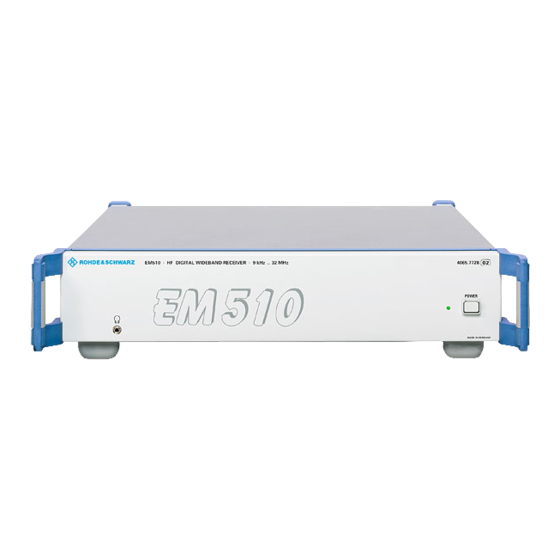
The fans expel the hot air to the sides. Both side panels are equipped with ventilation slots for drawing and expelling cooling air. On installing the EM510, sufficient room should be left at the sides of the unit to ensure an unhindered flow of hot air. - Page 17 Characteristics EM510 Fig. 2-1: Front View Fig. 2-2: Rear View 4065.7763.32-01.00...
- Page 18 EM510 Characteristics Fig. 2-3: Modules 4065.7763.32-01.00...
-
Page 19: Detailed Description
This section deals with the functions of the major functional blocks. 2.4.1 Power Supply Modules The EM510 operates either on AC or on DC. - DC voltage: 12 to 32 VDC - AC voltage: 100 to 240 VAC (115, 230 VAC nominal) with a frequency of 50 to 60 Hz If both voltage sources are connected, AC supply operation is favored. -
Page 20: Hf Receiver Module
EM510 Characteristics 2.4.2 HF Receiver Module The HF receiver module is controlled via the LAN interface X11. The necessary signal inputs and outputs of the HF receiver module are routed via RF cables to the connectors on the rear and front panel or are available through the opening in the rear panel. -
Page 21: Fans
Characteristics EM510 2.4.3 Fans The two 12-VDC fans for cooling the power s upply and the HF receiver module are supplied with a reduced voltage of approximately 8 VDC to operate the fans below maximum speed. This increases the life of the fans and additionally reduces acoustic noise. - Page 22 EM510 Characteristics Fig. 2-4: EM510 Detailed Block Diagram 4065.7763.32-01.00 2.10...
-
Page 23: Accessories
Characteristics EM510 2.5 Accessories Standard delivery of the EM510 comprises 1 mains connection cable 1 CD set including documentation and firmware & utilities The delivery note is always included. A screened battery cable is delivered by Rohde & Schwarz on request. - Page 24 EM510 Characteristics 4065.7763.32-01.00 2.12...
-
Page 25: Installation And Cabling
Installation and Cabling EM510 3 Installation and Cabling The EM510 is supplied completely assembled except for the handles and mounting brackets (use in rack), which come separately and must be attached by the user. 3.1 Unpacking and Checking Unpack the EM510. -
Page 26: Bench Operation
Note: Do not remove the enclosure when rack mounting the EM510. Place the EM510 onto the guide rails of the rack and insert it into the rack. Use the four screws of the front mounting bracket to fasten the unit to the rack. -
Page 27: Connection Of Power Supply
Note: If MIL-Spec regarding EMC must be fulfilled, a screened battery cable not exceeding 3 m in length is necessary. It is delivered by Rohde & Schwarz on request. The EM510 is connected to an external 12 to 32-VDC source (e.g. battery) by the connector X40 12 TO 32 VDC on the rear panel. -
Page 28: Antenna Connection
EM510 Installation and Cabling Installing the connector: Insert the Speakon NL4FX connector into the socket X40 on the rear panel. Turn the connector clockwise until it is locked into place and is secured by the safety-latch. Screw on the fitting for the hose (Fig. 3-2). -
Page 29: Connection Of External Reference (Optional)
EM510 3.5.3 Connection of External Reference (optional) The EM510 can be set to synchronize to an external frequency. To do so, apply the reference signal for the synchronization to socket X9 REF IN on the rear panel. - Frequency range: 1 to 20 MHz - RF level: 0 to +10 dBm - Z = 50 ... - Page 30 EM510 Installation and Cabling 4065.7763.32-01.00...
-
Page 31: Preparation For Use
- Check that the available supply voltage is between 12 and 32 VDC. The EM510 is switched on via the POWER switch. The POWER LED lights up after switch-on. 4.2 Local Control Except for the POWER LED and POWER switch the EM510 has no control elements. 4065.7763.32-01.00... -
Page 32: Functions Of Controls And Indicators
The LED will be on if the physical connection to the network is intact. LINK OK (rear panel, Fig. 4-1) Yellow LED The LED will flash yellow if the EM510 receives data from the network. The RECEIVE frequency of flashing is directly related to the network activity. (rear panel, Fig. 4-1) Fig. -
Page 33: Firmware Update
4.4.2.2 Preparations before Update via LAN Use the crossed LAN cable to connect the Ethernet port of the PC directly to the X11 of the EM510 Use the patch LAN cable to connect the hub or network to the X11 of the EM510... -
Page 34: Update Procedure
Windows. The version of WinPcap delivered with EM510 Update is not necessarily the most recent version. To obtain the most recent version of WinPcap as well as further information about the software kit, visit http://winpcap.polito.it/ . -
Page 35: Update Via Rs232
Update - via COM Start update process Switch on the EM510 within 30 seconds after the update has been started on the PC. 4.4.3.4 Update via Ethernet (LAN) In this mode you can update one or more targets using the same update software. -
Page 36: Messages And Indication
4.4.4.2 Indication on the EM510 front panel The lighted ACCE LED on the front panel of the EM510 shows that the update is in progress. After the update the ACCE LED is switched off and the FAIL LED is switched on. -
Page 37: Remote Control Via Lan With Scpi Command Syntax
See also Annex D: LAN Configuration. 4. The ping command is a simple way to check whether the controller is able to connect to the EM510. Just enter the command “ping <IP address>“ (e.g..: “ping 89.10.11.23“) “ in the DOS box. -
Page 38: Setting The Ip Address And Port Number
The configuration of the LAN interface is described in Annex D: LAN Configuration. IP address and port number settings will take effect immediately. The EM510 is capable of assuming an IP address dynamically assigned by RARP (see Annex D: LAN Configuration). -
Page 39: Structure And Syntax Of The Device Messages
Remote Control via LAN EM510 5.2 Structure and Syntax of the Device Messages 5.2.1 SCPI Introduction SCPI (Standard Commands for Programmable Devices) describes a standard command set for programming devices, irrespective of the type of device or manufacturer. The goal of the SCPI consortium is to standardize the device-specific commands to a large extent. - Page 40 EM510 Remote Control via LAN Device-specific commands Hierarchy: Device-specific commands are of hierarchical structure (see Figure 5-1). The different levels are represented by combined headers. Headers of the highest level (root level) have only one keyword. This keyword denotes a complete command system.
- Page 41 Remote Control via LAN EM510 Some keywords occur at several levels within one command system. Their effect depends on the structure of the command, that is to say, at which position in the header of a command they are inserted.
- Page 42 EM510 Remote Control via LAN Note: The short form is marked by upper-case letters, the long form corresponds to the complete word. Upper-case and lower-case notation only serve the above purpose, the device itself does not make any difference between upper- and lower-case letters.
-
Page 43: Structure Of A Command Line
Remote Control via LAN EM510 5.2.3 Structure of a Command Line Several commands in a line are separated by a semicolon ";". If the next command belongs to a different command system, the semicolon is followed by a colon. Example: SENSe:FREQuency:STARt MINimum;:OUTPut:FILTer:LPAS:STATe ON... -
Page 44: Responses To Queries
EM510 Remote Control via LAN 5.2.4 Responses to Queries A query is defined for each setting command unless explicitly specified otherwise. It is formed by adding a question mark to the associated setting command. According to SCPI, the responses to queries are partly subject to stricter rules than in standard IEEE 488.2. -
Page 45: Parameters
Remote Control via LAN EM510 5.2.5 Parameters Most commands require a parameter to be specified. The parameters must be separated from the header by a "white space". Permissible parameters are numerical values, Boolean parameters, text, character strings, block data and expressions. The type of parameter required for the respective command and the permissible range of values are specified in the command description (see 5.3"Description of Commands"). - Page 46 EM510 Remote Control via LAN INFinity represent + . In case of queries the numeric value 9.9E37 is output. The INF value 9.9E37 is entered into the result buffers MTRACE and ITRACE for MSCAN, FSCAN or PSCAN to identify the range limit.
- Page 47 Remote Control via LAN EM510 Block data Block data (Definite Length Block) are a transmission format which is suitable for the transmission of large amounts of data. A command using a block data parameter has the following structure: Example: HEADer:HEADer #45168xxxxxxxx ASCII character # introduces the data block.
-
Page 48: Overview Of Syntax Elements
EM510 Remote Control via LAN 5.2.6 Overview of Syntax Elements The following survey offers an overview of the syntax elements. The colon separates the key words of a command. In a command line the colon after the separating semicolon marks the uppermost command level. -
Page 49: Description Of Commands
Remote Control via LAN EM510 5.3 Description of Commands Note: For an overview of commands see the tables in Annex K. 5.3.1 Notation In the following sections, all commands implemented in the device are described in detail. The notation corresponds to a large extent to that of the SCPI standards. The SCPI conformity information can be taken from the list of commands in Annex K. - Page 50 EM510 Remote Control via LAN Special characters | A selection of keywords with an identical effect exists for some commands. These keywords are given in the same line and are separated by a vertical stroke. Only one of these keywords has to be indicated in the header of the command.
-
Page 51: Common Commands
Remote Control via LAN EM510 5.3.2 Common Commands The common commands are taken from the IEEE 488.2 (IEC 625-2) standard. A particular command has the same effect on different devices. The headers of these commands consist of an asterisk "*"... - Page 52 EM510 Remote Control via LAN *IDN? IDENTIFICATION QUERY queries the unit about identification. The output of the unit can be: "ROHDE&SCHWARZ,EM510,100.017/002, 01. 62-4065.8376.00" 100.017/002 serial number of the unit 01.62 firmware version number 4065.8376.00 firmware identity number *IST? INDIVIDUAL STATUS QUERY states the contents of the IST flags in decimal form (0 | 1).
- Page 53 Remote Control via LAN EM510 *RST RESET sets the device to a defined default status. The default setting is indicated in the description of the commands. *SRE 0 to 255 SERVICE REQUEST ENABLE sets the service request enable register to the value indicated. Bit 6 (MSS mask bit) remains 0.
-
Page 54: Abort Subsystem
EM510 ABORt Subsystem 5.3.3 ABORt Subsystem ABORt Stop command for measurement. This command stops an active scan. Parameters: none *RST state: none, as command is an event Example: ABORt 4065.7763.32-01.00 5.18... -
Page 55: Calculate Subsystem
CALCulate Subsystem EM510 5.3.4 CALCulate Subsystem CALCulate :IFPan :AVERage :TYPE MINimum|MAXimum|SCALar|OFF Setting of the averaging procedure for the IF-panorama data Parameters: MIN hold function is on MINimum MAX hold function is on MAXimum AVG averaging function is on SCALar Switching on the Clear Write function... - Page 56 EM510 CALCulate Subsystem :MARKer:MAXimum[:PEAK] Centering of the IF-panorama spectrum to the absolute level maximum Parameters: none Example: CALCulate:IFPan:MARKer:MAXimum :MARKer:MAXimum:LEFT Centering of the IF-panorama spectrum to the next relative level maximum left of the marker when the squelch is off. When it is on the center frequency is set to the next level maximum to the left which is above the squelch line.
-
Page 57: Calibration Subsystem
CALibration Subsystem EM510 5.3.5 CALibration Subsystem : ROSCillator[:DATA] <numeric_value> [MINimum|MAXimum|UP|DOWN] Changing the calibration value (D/A-converter value) for setting the exact OCXO reference frequency. Parameter: 0 ... 4095 <numeric_value> *RST state: none default state (not calibrated) 2048 Example: CALibration:ROSCillator UP : ROSCillator[:DATA]? [MINimum|MAXimum] Query about the calibration value (D/A-converter value) for setting the exact OCXO reference frequency. - Page 58 EM510 CALibration Subsystem : ROSCillator:DATE <year>,<month>,<day> Setting the calibration date. Result: <year>,<month>,<day> <year> = 1900.. <month> = 1..12 <day> = 1..31 Example: CALibration:ROSCillator:DATE 2003,07,24 : ROSCillator:DATE? Query about the calibration date. Result: <year>,<month>,<day> <year> = 1900.. <month> = 1..12 <day> = 1..31 Example: CALibration:ROSCillator:DATE? ->...
-
Page 59: Diagnostic Subsystem
DIAGnostic Subsystem EM510 5.3.6 DIAGnostic Subsystem DIAGnostic[:SERVice] :INFO :SDATe<numeric_suffix>? Query about the software-generation date If a module is not available, a zero string ("") is returned and the error message HW MISSING will be generated. Parameters: The processor is selected via the <numeric suffix>: 1 or no <numeric suffix>... - Page 60 EM510 DIAGnostic Subsystem :MODule? <module_name> Read-out of a module information. Parameters: Abbreviation of the name of the module to be queried: <module_name> preselection HF tuner mainboard all modules Result: Abbreviation of the module name <module_name>, <PartNumber>, Module ID (e.g. 4065.7840.02) <HwCode>,...
- Page 61 DIAGnostic Subsystem EM510 :MODule:STATe? <module_name> Output of additional information of one or all modules. Parameters: information relating to module to be queried: <module_name> preselection mainboard all modules Result: The module is "UNDEFINED". The EEPROM data are corrupt. <module_name>,0 The module is "OK".
- Page 62 EM510 DIAGnostic Subsystem :MONitor? <module> Output of test-point information of one or all recognized modules. Parameters: information relating to module to be queried: <module_name> preselection mainboard all modules Result: If the output format is set to ASCII, all information relating to the test points of a known module are output in a table.
- Page 63 DIAGnostic Subsystem EM510 :TEMPerature[<numeric_suffix>]? Output of the temperature at various measurement points of the device. Parameters: The measurement point (1 to 5) is selected through the <numeric suffix>. 1 or none <numeric suffix> TEMP_LOCAL temperature on the mainboard TEMP_FPGA temperature of the FPGA...
-
Page 64: Display Subsystem
EM510 DISPlay Subsystem 5.3.7 DISPlay Subsystem DISPlay :MENU[:NAME] <menu_name> Selection of a specific data channel for the video panorama display from the pre-set list. In addition to the channel, this sets the pre-conditioning of the selected time signal. Please note that the demodulation mode should correspond to the channel selection and pre-conditioning. -
Page 65: Format Subsystem
FORMat Subsystem EM510 5.3.8 FORMat Subsystem FORMat :BORDer NORMal|SWAPped Specifies whether binary data is first to be transferred with low or high byte. Note: This command affects only the trace data. For UDP data there is a separate setting option. - Page 66 EM510 FORMat Subsystem [:DATA]? Query about the output format of the above-mentioned queries. Parameters: none Result: ASC, PACK Example: FORMat? -> PACK :DIAGnostic:MONitor ASCii|PACKed Sets the output format for the query DIAGnostic:MONitor?. Parameters: output in ASCII format ASCii output in internal binary data format...
- Page 67 FORMat Subsystem EM510 :MEMory ASCii|PACKed Specifies the output format of the queries MEMory:CONTents? Parameters: output in ASCII format ASCii output in internal binary data format PACKed *RST state: ASCii Example: FORMat:MEMory PACKed :MEMory? Query about the output format of above-mentioned queries.
- Page 68 EM510 FORMat Subsystem :SREGister? Query with which data format the above-mentioned queries are carried out. Parameters: none Result: ASC, BIN, HEX Example: FORMat:SREGister? -> HEX 4065.7763.32-01.00 5.32...
-
Page 69: Initiate Subsystem
INITiate Subsystem EM510 5.3.9 INITiate Subsystem INITiate [:IMMediate] Start command to initiate measurement. Is also used as a start command for different SCAN types. If SENSe:FREQuency:MODE is set on CW|FIXed a measurement is carried out with every INITiate command and the measurement result might be stored in MTRACE or ITRACE. -
Page 70: Input Subsystem
EM510 INPut Subsystem 5.3.10 INPut Subsystem INPut :ATTenuation<numeric_value> Setting the attenuator. Parameters: 0 to 25 dB <numeric_value> *RST state: Example: INPut:ATTenuation 15 :ATTenuation? Query about the current attenuation. Parameters: none Result: 0 to 25 dB <numeric_value> Example: INPut:ATTenuation? -> 15 4065.7763.32-01.00... - Page 71 INPut Subsystem EM510 :ATTenuation:AUTO <Boolean> Setting attenuation so that the best dynamic range is obtained; explicit switch on/off of attenuator sets AUTO to OFF. Parameters: attenuation is coupled to input-signal strength attenuation is manually switched *RST state: Example: INPut:ATTenuation:AUTO ON :ATTenuation:AUTO? Query about the automatically attenuation setting.
- Page 72 At this setting with ATT OFF, excessively strong signals (approx. >97 dBµV) at the antenna entry may cause an overload of the A/D converter. Notes: As opposed to the EM550, the EM510 modes "Normal“ and "Low Noise“ are identical in meaning. However, both modes are permitted for reasons of compatibility. Parameters:...
- Page 73 INPut Subsystem EM510 reception with low distortion LOWD normal reception NORM Example: INPut:ATTenuation:MODE? -> LOWD 5.37 4065.7763.32-01.00...
-
Page 74: Measure Subsystem
EM510 MEASure Subsystem 5.3.11 MEASure Subsystem MEASure :BANDwidth:MODE XDB|BETA Selection of bandwidth measurement method. Parameters: bandwidth measurement method x dB bandwidth measurement method Beta % BETA *RST state: Example: MEASure:BANDwidth:MODE :BANDwidth:MODE? Query about the selected bandwidth measurement method. Result: bandwidth measurement method x dB... -
Page 75: Continuous Measuring Mode
MEASure Subsystem EM510 :BANDwidth:BETA<numeric_value> Configuration of bandwidth measurement method Beta %. Parameter: 0.1 to 99.9 % <numeric_value> *RST state: 1.0 % Example: MEASure:BANDwidth:BETA 10 :BANDwidth:BETA? Query about the configuration of bandwidth measurement method Beta %. Result: % value of bandwidth measurement method Beta %. -
Page 76: Measuring Time
EM510 MEASure Subsystem :MODE? Query about the set measuring mode. Parameters: none Result: continuous measurement CONT periodic measurement Example: MEASure:MODE? -> PER :TIME <numeric_value>|MINimum|MAXimum|DEFault Setting the duration for all measurement functions. Note: The user is responsible for setting a useful measuring time. Time spans which are too short lead to faulty measurement results. -
Page 77: Memory Subsystem
EM510 5.3.12 MEMory Subsystem This subsystem contains all the functions necessary to operate the EM510 memory locations. The memory locations are addressed with the text (see "Parameters" on page 5.9) MEM0 to MEM9999 (memory location 0 to memory location 9999). Some commands allow the receiver (data set of receiver settings) to be addressed by Character Data RX, the currently set memory location by CURRENT and the next free memory location by NEXT . - Page 78 EM510 MEMory Subsystem :CONTents <name>,<mem_paras>|<packed_struct> Loading a memory location. As an alternative to the parameter field (<mem_paras>) a <Definite Length Block> can be transferred with binary data. Parameters: MEM0 to MEM9999 | RX | CURRENT | NEXT <name> <mem_paras> <F>, <THR>, <DEM>, <BW>, <ANT>, <ATT>, <ATTA>, <SQUC>, <AFC>, <ACT>...
- Page 79 MEMory Subsystem EM510 binary data set as <Definite Length Block> with the <packed_struct> following structure: Frequency in Hz 4 bytes = unsigned long integer Squelch threshold in 1/10 dBuV 2 bytes = signed integer Demodulation type 2 bytes = meaning:...
- Page 80 EM510 MEMory Subsystem :CONTents? <name>|RX Query about contents of memory location. Parameters: MEM0 to MEM9999 | RX | CURRENT <name> Result: Depending on the setting by the command FORMat:MEMory either an ASCII data set or a binary data set is output: The ASCII data set has the following structure: <F>,<THR>,<DEM>,<BW>,<ANT>,<ATT>,<ATTA>,<SQUC>,<AFC>,<ACT>...
- Page 81 MEMory Subsystem EM510 :MPAR <name>,<ACT> Setting the memory location parameter (MPAR = MemoryPARameter) <ACT> . Parameters: MEM0 to MEM9999 | CURRENT <name> setting/resetting the memory to the scan (ON/OFF or 1/0) <ACT> Example: MEMory:CONTents:MPAR MEM1, OFF :MPAR? <name> Query about memory-location parameter <ACT>.
-
Page 82: Output Subsystem
EM510 OUTPut Subsystem 5.3.13 OUTPut Subsystem OUTPut :AUXMode FREQuency|ANTCtrl The switch "AUXMode" determines whether the frequency in BCD or the antenna number in BCD and the CTRL byte are output via X12b at the front panel. Parameters: frequency output at "AUX"... - Page 83 OUTPut Subsystem EM510 :BITAux [<numeric_suffix>] [:STATe] <Boolean> Sets the AUX bits at the rear panel. <numeric_suffix> byte 1 corresponds to CTRL1 at X12B.14'AUX' byte 2 corresponds to CTRL2 at X12B.15'AUX' byte 3 corresponds to CTRL3 at X12B.16'AUX' byte 4 corresponds to CTRL4 at X12B.17'AUX' byte 5 corresponds to CTRL5 at X12B.18'AUX'...
- Page 84 EM510 OUTPut Subsystem :BYTAux [:STATe] <numeric_value> Sets the 8 AUX bits by a single byte command. Parameters: value of the AUX bytes (0 to 255, #H00 to #HFF or #B0 <numeric_value> to #B11111111) *RST state: Example: OUTPut : BYTAux 7 .
- Page 85 OUTPut Subsystem EM510 :FILTer:MODE? Query about the activated audio filter mode. Parameters: none Result: no filter function automatic elimination of interference signals NOTC noise reduction filter bandpass filter 300 Hz to 3.3 kHz Example: OUTPut:FILTer:MODE? ->NOTC :FPDP:MODE IF|DEModulator|PANorama With this switch the kind of data is determined that is output via the FPDP interface.
- Page 86 EM510 OUTPut Subsystem :FPDP:MODE? Query about the kind of data that is output via the FPDP interface. Parameters: none Result: IQ data, digital IF data (before the demodulation) (see also: SYSTem:FPDP:REMote:MODE ) video streaming data (after the demodulation), 2-channelled IQ data from the panorama path Example: OUTPut:FPDP:MODE? ->PAN...
- Page 87 OUTPut Subsystem EM510 . :CONTrol MEMory|NONE Selection of the source for the operating state after switching the unit on, when reading the memory locations by the MEMory:COPY command, when using the RCL key or when running memory scan. Parameters: squelch state and squelch value are read out of the memory...
- Page 88 EM510 OUTPut Subsystem :THReshold [:UPPer] <numeric_value>|UP|DOWN|MINimum|MAXimum Setting the squelch threshold. Parameters: squelch threshold in dBuV <numeric_value> increase|decrease of squelch threshold by the value set with the UP|DOWN command OUTPut:SQUelch:THReshold[:UPPer]: STEP[:INCRement]. sets the lowest/highest squelch threshold MINimum|MAXimum *RST state: 10 dBuV...
- Page 89 OUTPut Subsystem EM510 [:INCRement]? [MINimum|MAXimum] Query about the stepwidth. Parameters: none query about currently set stepwidth query about smallest|largest stepwidth MINimum|MAXimum Result: Stepwidth of squelch threshold in dB V Example: OUTP:SQU:THR:STEP? -> 10 5.53 4065.7763.32-01.00...
- Page 90 EM510 OUTPut Subsystem :VIDeo:FREQuency <numeric_value>|MINimum|MAXimum Setting the center frequency of the analog IF output. This command is only effective if the video mode was set on IF. Parameters: frequency value <numeric_value> sets the lowest/highest center frequency MINimum|MAXimum *RST state: 10700000...
- Page 91 OUTPut Subsystem EM510 :VIDeo:MODE IF|DEModulator The video-mode switch determines whether the analog IF or the analog demodulated video signal is output at the front panel through one of the connectors "Video A X6" or "Video B X7". In the case of an analog IF, the center frequency can be set by the OUTPut:VIDeo:FREQuency command.
-
Page 92: Route Subsystem
EM510 ROUTe Subsystem 5.3.14 ROUTe Subsystem Two signal path switches (signal routing) are equipped in the EM510. The command ROUTe without numeric suffix or with numeric suffix 1 is used for the antenna selector 1 to 99. The command ROUTe with numeric suffix 2 is used for the crosspoint switch for Gigacast, FPDP and the regenerating paths. - Page 93 ROUTe Subsystem EM510 OPEN :ALL Do not select antenna (antenna number 0 is set). Parameters: none *RST state: none, as command is an event Example: ROUTe:OPEN:ALL SELect <channel_list>|UP|DOWN|MINimum|MAXimum Corresponds to the following combination: ROUTe:OPEN:ALL ROUTe:CLOSe <channel_list> Parameters: must contain one number max. (0 to 99) <channel_list>...
-
Page 94: Sense Subsystem
[:RESolution] <numeric_value>|UP|DOWN|MINimum|MAXimum Selection of demodulation bandwidth. Since in the EM510 the signal path is also used for the computation of the IF panorama, both the selection of the IF panorama and the selected demodulation bandwidth affect the selection of the preselection filter ranges. - Page 95 SENSe Subsystem EM510 : CORRection:ATTenuation? Read out of the current total attenuation in the signal path from antenna input to IQ output. The attenuation depends on the current receiver frequency and the current temperature. The absolute signal power can be calculated by adding this value to the IQ data level dB full scale. The automatic attenuation selection and the automatic gain control has to be switched off in this case.
-
Page 96: Annex F: Datagram Communication
EM510 SENSe Subsystem : DECoder:SELCall[:STATe] ON|OFF|1|0 Switching on and off the Sel Call Analysis. The following selective call methods can be detected and decoded: CCIR7(2), CCIR1, CCITT, EEA, EIA, EURO, NATEL, VDEW, ZVEI1, ZVEI2, DTMF, CTCSS, DCS The decoder automatically detects the most probable code and only this code is output. If several codes of equal probability are detected then all codes are output. - Page 97 SENSe Subsystem :DATA? EM510 :DATA? [<data_handle>] Query about the current measured values of active sensor functions. When only the command SENSe:DATA? is used to query measured values, the measured values reported back may be as old as 200 ms. For display on the unit measured values are captured every 200 ms and put into a buffer.
- Page 98 EM510 SENSe Subsystem :DATA? Result: Level in dBuV, offset in Hz The output format will be generated with the command FORMat:DATA according to the setting: normal ASCII output ASCii PACKed <Definite Length Block>: level in 1/10 dBuV (2 Byte) offset in Hz (4 Byte)
- Page 99 SENSe Subsystem :DEModulation EM510 :DEModulation AM|FM|PULSe|PM|A0|IQ|ISB|A1|CW|LSB|USB Switchover of type of demodulation. Error message: If the set bandwidth exceeds 9 kHz at CW, LSB and USB, an error -221,"Settings conflict" will be generated if one of the SSB operating modes is to be switched on.
- Page 100 EM510 SENSe Subsystem :DEModulation :DEModulation:BFO <numeric_value> | MIN | MAX Setting the BFO frequency. The BFO is an auxiliary oscillator which, in CW mode, helps to recover carriers. Parameters: BFO frequency (-8 kHz to +8 kHz) <numeric_value> setting the minimum/maximum frequency...
- Page 101 SENSe Subsystem :DETector EM510 :DETector . [:FUNCtion] POSitive|PAVerage|FAST|RMS Switching over the level-measuring process. Parameters: measuring the peak value (PEAK) POSitive measuring the average value of the voltage (AVG) PAVerage measuring the current value (FAST) FAST measuring the average value of the power (RMS)
- Page 102 EM510 SENSe Subsystem :DETector :RDS[:STATe] 0|1|ON|OFF Switching on or off the RDS decoder. Note: The RDS decoder is accessible only with installed software option EM510IM (ITU Measurement). Parameters: ON|1 Decoder switched on OFF|0 Decoder switched off *RST state: Example: FM:RDS ON .
- Page 103 SENSe Subsystem :DETector EM510 . :RDS:DATA? Query about the RDS data. Parameters: none Result: Flags, PI-Code, TP, TA, MS, DI Meaning: Flags: Bit 0 -> Stereo pilot tone detected / not detected Bit 1 -> ARI carrier detected / not detected Bit 2 ->...
- Page 104 EM510 SENSe Subsystem :DETector :RDS:PS? Query about RDS program string name. Parameters: none Result: Definite length binary block Identification of the radio station coded in binary data ‘_‘ stands for characters not transmitted yet Example: FM:RDS:PS? #18BAYERN 3 . :RDS:RT? Query about RDS radio text.
- Page 105 SENSe Subsystem :DETector EM510 :STEReo[:STATe] 1|0|ON|OFF Switching on/off the stereo decoder. Parameters: 1|ON switching on the stereo decoder 0|OFF switching off the stereo decoder Example: FM:STEReo ON . :STEReo[:STATe]? Query about the state of the stereo decoder. Parameters: none Example: FM:STEReo? ...
- Page 106 EM510 SENSe Subsystem:FREQuency :FREQuency :AFC <Boolean> Switching on/off the AFC function. Parameters: AFC function on AFC function off *RST state: Example: SENSe:FREQuency:AFC ON :AFC? Query about the AFC function Parameters: none Result: AFC function on AFC function off Example: SENSe:FREQuency:AFC? -> 1 [:CW|FIXed] <numeric_value>|UP|DOWN|MINimum|MAXimum...
- Page 107 SENSe Subsystem:FREQuency EM510 [:CW|FIXed]? [MINimum|MAXimum] Query about the receiver frequency. Parameters: none query about the current receiver frequency query about the lowest|highest receiver frequency MINimum|MAXimum Result: Frequency value in Hz Example: FREQuency? -> 801000 :MODE CW|FIXed|SWEep|MSCan|PSCan Changing the operating mode of the receiver.
- Page 108 EM510 SENSe Subsystem:FREQuency :PSCan If the STARt and/or the STOP frequency is changed, CENTer or SPAN is matched. If CENTer and/or SPAN is changed, STARt- and STOP frequency are matched. In a command either CENTer and SPAN or STARt- and STOP frequency can be changed simultaneously.
- Page 109 SENSe Subsystem:FREQuency EM510 :SPAN? [MINimum|MAXimum] Query about the display range of the panorama scan. Parameters: none query about the current display range query about the smallest/widest display range MINimum|MAXimum Result: Frequency value in Hz Example: FREQuency:PSCan:SPAN? -> 2000000 :STARt <numeric_value>|MINimum|MAXimum Setting of the start frequency of the panorama scan.
- Page 110 EM510 SENSe Subsystem:FREQuency :STOP <numeric_value>|MINimum|MAXimum Setting of the stop frequency of the panorama scan. Parameters: frequency value <numeric_value> Setting of the lowest/highest stop frequency MINimum|MAXimum *RST state: 2 MHz Example: FREQuency:PSCan:STOP 4 MHz :STOP? [MINimum|MAXimum] Query about the stop frequency of the panorama scan.
- Page 111 SENSe Subsystem:FREQuency EM510 :SPAN<numeric_value>|UP|DOWN |MINimum|MAXimum Selection of frequency range with option IF-panorama. The following ranges are available: 10 kHz, 25 kHz, 50 kHz, 100 kHz, 150 kHz, 256 kHz, 300 kHz, 400 kHz, 600 kHz, 800 kHz, 1200 kHz , 2400 kHz, 4800 kHz und 9600 kHz. The entered frequency must exactly correspond to the upper values.
- Page 112 EM510 SENSe Subsystem:FREQuency :STARt <numeric_value>|MINimum|MAXimum Setting the start frequency of a frequency scan. Parameters: frequency <numeric_value> sets the lowest|highest start frequency MINimum|MAXimum *RST state: 1 MHz Example: FREQuency:STARt 1.5 MHz :STARt? [MINimum|MAXimum] Query about the start frequency of a frequency scan.
- Page 113 SENSe Subsystem:FREQuency EM510 [:INCRement]? [MINimum|MAXimum] Query about the stepwidth. Parameters: none query about the currently set stepwidth query about the smallest|largest stepwidth MINimum|MAXimum Result: Frequency stepwidth in Hz Example: FREQuency:STEP? -> 2000 :STOP <numeric_value>|MINimum|MAXimum Setting the stop frequency of a frequency scan.
- Page 114 EM510 SENSe Subsystem:FUNCtion :FUNCtion If the sensor function(s) is (are) changed, the trace data set MTRACE is always deleted. :CONCurrent <Boolean> Determines whether several sensor functions can at the same time be switched or not. If CONCurrent = OFF, the command SENSe:FUNCtion[:ON] has the effect of a 1-out-of-n selection (one is switched on, the previously activated is automatically switched off).
- Page 115 SENSe Subsystem:FUNCtion EM510 :OFF <sensor_function> {,<sensor_function>} Switching off one or several sensor functions. Parameters: see SENSe:FUNCtion[:ON] *RST state: "FREQ:OFFS" Example: FUNCtion:OFF "FREQ:OFFS" :OFF? Query about the sensor functions being switched off. Parameters: none Result: List of the sensor functions being switched off. For strings see SENSe:FUNCtion[:ON] Example: FUNCtion:OFF? ->...
- Page 116 EM510 SENSe Subsystem:FUNCtion [:ON] <sensor_function> {,<sensor_function>} Switch on of one or several sensor functions. Error message: If CONCurrent = OFF, an error -108, "Parameter not allowed" will be generated for ten or more parameters. Parameters: <sensor_function> is one of the following strings: switch on level measurement "VOLTage:AC"...
- Page 117 SENSe Subsystem:FUNCtion EM510 [:ON]? Query about sensor functions being switched on. Parameters: none Result: List of sensor functions switched on. If no function is active, a zero string ("") is output. The list has a specific order: 1. level measurement function 2.
- Page 118 EM510 SENSe Subsystem:GCONtrol :GCONtrol [:FIXed|MGC] <numeric_value>|UP|DOWN|MINimum|MAXimum Setting the MGC value. Parameters: gain control factor in dBµV <numeric_value> -30 dBµV = no gain control -> maximum sensitivity 110 dBµV = maximum gain control -> minimum sensitivity increase|decrease of the MGC value by the value set in the...
- Page 119 SENSe Subsystem:GCONtrol EM510 :AUTO:TIME? :AGC:TIME? Query about the gain control time. Result: slow gain control time SLOW default gain control time fast gain control time FAST Example: GCONtrol:AUTO:TIME? -> FAST :STEP [:INCRement] <numeric_value>|MINimum|MAXimum Setting the stepwidth for the command SENSe:GCONtrol[:FIXed|MGC] UP|DOWN.
- Page 120 EM510 SENSe Subsystem:GCONtrol [:INCRement]? [MINimum|MAXimum] Query about the MGC stepwidth. Parameters: none query about the currently set stepwidth query about the smallest|largest stepwidth MINimum|MAXimum Result: MGC stepwidth in dB Example: GCONtrol:STEP? -> 10 :MODE FIXed|MGC|AUTO|AGC Type of gain control. Parameters:...
- Page 121 SENSe Subsystem :MSCan EM510 :MSCan The MSCan system controls the frequency function of the device, provided the memory scan has been activated by SENSe:FREQuency:MODE MSCan. Each scan is started by INITiate[:IMMediate]. The memory locations are placed in the MEMory subsystem and are set for query during the scan.
- Page 122 EM510 SENSe Subsystem :MSCan [:ON]? Query about the scan-control mechanism that is switched on. Parameters: none Result: A list of the scan-control mechanisms that are switched on is output. If there is nothing switched on then a zero string ("") is output.
- Page 123 SENSe Subsystem :MSCan EM510 :COUNt <numeric_value>|MINimum|MAXimum|INFinity Information about the number of MSCans. Parameters: number of scans <numeric_value> minimum|maximum number MINimum|MAXimum infinite number INFinity *RST state: INFinity Example: MSCan:COUNt 100 :COUNt? [MINimum|MAXimum] Query about the number of MSCans. Parameters: none query about the current number of scans...
- Page 124 According to the SCPI standard, this command is used to set the dwell time per scan step, i.e. the time required by a step. This definition is met in the EM510 if the squelch is switched off. The hold criterion is then fulfilled for each step.
- Page 125 SENSe Subsystem :MSCan EM510 :HOLD :TIME <numeric_value>|MINimum|MAXimum Setting the hold time during signal-controlled scan continuation. If the signal disappears during the dwell time, the hold time is started. After completion of the hold time, the scan is continued with the next frequency even if the dwell time has not yet been completed.
- Page 126 EM510 SENSe Subsystem :PSCan :PSCan The PSCan system checks the frequency function of the unit in case a panorama scan was initiated by SENSe:FREQuency:MODE. Each scan is started only by INITiate[:IMMediate]. :COUNt <numeric_value>|MINimum|MAXimum|INFinity Output of a number of PSCan cycles.
- Page 127 SENSe Subsystem :ROSCillator EM510 :ROSCillator Control of reference oscillator. :EXTernal :FREQuency? Query about the given external reference frequency. Parameters: none Result: 10000000 Example: ROSCillator:EXTernal:FREQuency? -> 10000000 [:INTernal] :FREQuency? Query about the internal reference frequency. Parameters: none Result: 10000000 Example: ROSCillator:FREQuency? -> 10000000 :SOURce INTernal|EXTernal Setting whether external or internal reference frequency is to be used.
- Page 128 EM510 SENSe Subsystem :ROSCillator :SOURce? Query about the reference oscillator to be used. Parameters: none Result: internal reference oscillator external reference oscillator Example: ROSCillator:SOURce? -> EXT 4065.7763.32-01.00 5.92...
- Page 129 SENSe Subsystem :SWEep EM510 :SWEep The SWEep system controls the frequency function of the device if the frequency scan has been activated by the SENSe:FREQuency:MODE SWEep command. Each scan is initiated by INITiate[:IMMediate]. :CONTrol :[ON] <control _function> {,<control_function>} Command for switch-on of the STOP:SIGNalfunctions.
- Page 130 EM510 SENSe Subsystem :SWEep :OFF <control_function>{,<control_function} Switch-off of one or several scan-control functions. Parameters: see SENSe:SWEEp:CONTrol [:ON] *RST state: after *RST there is no control function running Example: SWEep:CONTrol:OFF "STOP:SIGN" :OFF ? Query about the switched-off scan-control functions. Parameters: none Result: List of switched-off control functions.
- Page 131 SENSe Subsystem :SWEep EM510 :COUNt? [MINimum|MAXimum] Query about the number of sweeps. Parameters: none query about the current number of sweeps query about the minimum|maximum sweeps MINimum|MAXimum Result: Number of sweeps; 9.9E37 is output for an infinite number Example: SWEep:COUNt? -> 100 :DIRection UP|DOWN Setting the scan direction.
- Page 132 According to the SCPI standard, this command is used to set the dwell time per scan step, i.e. the time required by a step. This definition is met in the EM510 if the squelch is switched off. The hold criterion is then fulfilled for each step.
- Page 133 SENSe Subsystem :SWEep EM510 :TIME? [MINimum|MAXimum] Query about the hold time during signal-controlled scan continuation. Parameters: none query about the current hold time query about the lowest|highest hold time MINimum|MAXimum Result: Hold time in seconds Example: SWEep:HOLD:TIME? 0.010 :STEP<numeric_value>|MINimum|MAXimum Setting the frequency stepwidth for the frequency scan.
- Page 134 EM510 SENSe Subsystem :SWEep :SUPPress Insert current frequency into suppress list. The range is obtained from the bandwidth according to the following formulae: SSTARTn = SENSn: FREQ - SENSn:BAND/2 SSTOPn = SENSn: FREQ + SENSn:BAND/2 The frequency pair is inserted into an empty space of the trace. Free spaces (gaps) are characterized by a frequency pair with the values 0.0.
-
Page 135: Status Subsystem
STATus Subsystem EM510 5.3.16 STATus Subsystem The following STATus register commands are possible according to SCPI standard: STATus :OPERation :CONDition? :ENABle <numeric_value> :ENABle? [:EVENt]? :NTRansition <numeric_value> :NTRansition? :PTRansition <numeric_value> :PTRansition? :SWEeping :CONDition? :ENABle <numeric_value> :ENABle? [:EVENt]? :NTRansition <numeric_value> :NTRansition? :PTRansition <numeric_value>... - Page 136 EM510 STATus Subsystem Exemplifying all STATus register commands, for example the STATus:OPERation:SWEeping register, the commands of the STATus:OPERation register are explained as follows. STATus OPERation :CONDition? Query about the condition section of the OPERation status register. Parameters: none Result: Depending on the setting by the FORMat:SREGister command, the contents of the register are transferred as a decimal, binary or hexadecimal value in the ASCII code.
- Page 137 STATus Subsystem EM510 [:EVENt]? Query about the event section of the OPERation status register. Parameters: none Result: Depending on the setting by the FORMat:SREGister command, the contents of the register are transferred as a decimal, binary or hexadecimal value in ASCII code.
- Page 138 EM510 STATus Subsystem :PTRansition <numeric_value> Setting the positive transition filter of the OPERation status register. Parameters: value of the PTRansition section (0..65535 or <numeric_value> #H0000..#HFFFF or #B0..#B1111111111111111) *RST state: will not be changed by *RST Example: STATus:OPERation:PTRansition #B11111111 :PTRansition? Query about the positive transition filter of the OPERation status register.
- Page 139 STATus Subsystem EM510 :PRESet Setting the STATus registers with default values: Register ENABle/PTR/NTR PRESet value STATus:OPERational ENABle 65535 STATus:QUEStionable ENABle 65535 STATus:TRACe ENABle 65535 65535 STATus:EXTension ENABle 65535 65535 STATus:OPERation:SWEep ENABle 65535 65535 Parameters: none *RST state: none, as command is an event...
-
Page 140: System Subsystem
EM510 SYSTem Subsystem 5.3.17 SYSTem Subsystem SYSTem:AUDIo:BALance <numeric_value> MINimum|MAXimum Sets the balance of AF for the headphones. Parameters: balance of AF from -0.5 to +0.5 <numeric_value> -0.5 = only left channel = mid position = only right channel only left AF channel | only right AF channel... -
Page 141: Configuration
SYSTem Subsystem EM510 :AUDio:REMote:MODE <numeric_value> Sets the mode of the digital AF that is transferred via the remote control interface per UDP. See also Annex D: LAN Configuration. Parameter: Mode 0 to 12 of digital AF <numeric_value> Mode Sampling rate... -
Page 142: Annex B: Data Stream Format
EM510 SYSTem Subsystem :FPDP:REMote:MODE OFF | SHORt | LONG | FLAGs | AMMos Sets the format of the digital data (panorama, IF or demodulated data) that is output by FPDP. If command OUTPut:FPDP:MODE has been used to set the format to DEModulator (demodulated data), the demodulation modes AM, FM, PULS and PM will result in an output of AM instead of I, and of FM instead of Q. - Page 143 SYSTem Subsystem EM510 : FPDP:REMote:MODE? Query about the set data format. Parameters: none Result: digital data switched off digital data in the format 16 Bit I and 16 Bit Q SHOR digital data in the format 32 Bit I and 32 Bit Q...
- Page 144 EM510 SYSTem Subsystem :IF:REMote:MODE OFF | SHORt | LONG Sets the mode of the digital IF that is transferred via the remote control interface per UDP. Parameters: digital IF switched off digital IF format 16 bit I and 16 bit Q...
- Page 145 SYSTem Subsystem EM510 :VIDeo:REMote:MODE OFF | SHORT | LONG Sets the mode of the digital video output that is transferred via the remote control interface per UDP. The output depends on which demodulator has been switched on. See also command DISPlay:MENU.
- Page 146 EM510 SYSTem Subsystem :AUDio:VOLume <numeric_value>|MINimum|MAXimum Sets the volume of AF for loudspeakers and headphones. Parameters: volume of AF from 0 to 1 <numeric_value> = no AF = full volume of AF no AF | full volume of AF MINimum|MAXimum Note: The parameter is rounded to the next internally settable discrete value.
- Page 147 When ordering a software option the serial number of the EM510 (for example 100217/002) must be indicated. This number is on the sticking-label at the front panel or in the ident string (command: *idn?).
-
Page 148: Test Subsystem
EM550 TEST-Subsystem 5.3.18 TEST Subsystem The selftest can be run with two different test routines. The basic test runs continuously in the background and tests the test points inside the module. Based on this test, a "short test" or a "long test" can be triggered. -
Page 149: Trace Subsystem
TRACe Subsystem EM510 5.3.19 TRACe Subsystem Traces are used for summarizing data. The following traces are available: Result trace: For the results, two predefined traces (MTRACE = Measurement Trace and ITRACE = Information Trace)are available. They cannot be deleted. Via the control instruction, a condition can be defined which can preselect the data to be written into the MTRACE or ITRACE. - Page 150 EM510 TRACe Subsystem Suppress trace: Remote sees the suppress lists as predefined traces. Each data set contains two traces with the names SSTART (= Suppress START) and SSTOP (=Suppress STOP). The suppress list has 100 elements with each element consisting of two frequencies. The frequency pair specifies a frequency range which is suppressed during the scan.
- Page 151 TRACe Subsystem EM510 TRACe|DATA Note: Instead of command word TRACe, DATA may be used as well. :CATalog? Query about all defined trace names. Note: IFPAN trace is only available with the software option EM510IM (ITU Measurement) or software option EM510SU (Spectrum Unit) installed.
- Page 152 EM510 TRACe Subsystem [:DATA] <trace_name> Query about the trace data. Error message: If the trace name is unknown, an error -141,"Invalid character data" will be generated. Parameters: name of desired trace as <Character Data> (MTRACE, ITRACE, IFPAN or <trace_name> SSTART, SSTOP)
- Page 153 TRACe Subsystem EM510 (see "Block data" on page 5.11) PACKed -> <Definite Length Block>: level in 1/10 dBuV (2 bytes) offset in Hz (4 Byte)AM - modulation index in 1/10 % (2 bytes) AM - positive modulation index in 1/10 % (2 bytes) ...
- Page 154 EM510 TRACe Subsystem The following is valid for the IFPAN trace: Output of the spectrum data. If there are no data available then a NaN (Not a Number) will be output. The output format of the IFPAN trace depends on the settings made by command FORMat:DATA.
- Page 155 TRACe Subsystem EM510 :FEED? <trace_name> Query about the data block connected with the trace. Error message: If the trace name is unknown, an error -141, "Invalid character data" will be generated. Parameters: see TRACe[:DATA]? <trace_name> Result: Name of the block coupled to the trace.
- Page 156 EM510 TRACe Subsystem :LIMit [:UPPer] <trace_name>, <numeric_value>|MINimum|MAXimum Setting the limit of a trace. If the limit is exceeded, the Limit exceeded Flag will be set in the STATus:TRACe register. Error message: If the trace name is unknown, an error -141, "Invalid character data" will be generated.
- Page 157 TRACe Subsystem EM510 :POINts? <trace_name>[,MINimum|MAXimum] Query about the number of values stored in a trace. The number of values stored in the suppress traces is always 100. Thus, the MAXimum and MINimum value is also 100. The number of IFPAN trace values is always 2047.
- Page 158 EM510 TRACe Subsystem :VALue? <trace_name>, <index>, <numeric_value> Setting an element of a trace. Note: Only suppress traces can be set. Error message: If the trace name is unknown or not equal to a suppress trace name, an error -141, "Invalid character data"...
-
Page 159: Device Model And Command Processing
The following figure shows the basic structure of the unit under firmware aspects. The actual receiver is isolated from the remote control units by a central data memory. This memory is at the core of the EM510 firmware and deals with the following tasks: Administration of connected modules (receiver, remote clients) ... -
Page 160: Remote Client
EM510 Remote Control via LAN Example 1: Remote client 1 modifies the frequency value. The central memory signals to the receiver that a new frequency is to be set. The remote client 2 (if connected) is supplied with the new frequency. Every remote client receives a modification report (see "STATus:EXTension Register"... -
Page 161: Protocol
When the unit is started, a so-called list socket is generated. It functions as the unit's "receptionist". Each host wishing to remote-control the EM510 has to log in with the list socket first. The list socket then generates a new remote client and allocates the link to a new socket so the list socket remains free to receive further hosts. - Page 162 1174, is a supplement to IEEE 488, making it applicable also to LAN and serial links (RS232). The EM510 uses this standard as a basis for SCPI commands via sockets. Each identified setting command contained in an SCPI string is first stored in a buffer memory. Only a <Program Message Terminator>...
-
Page 163: Data Memory
Remote Control via LAN EM510 5.4.2 Data Memory This figure shows the classification of data into data groups. These groups are also reflected by the Status Reporting System of the remote clients in the extension register status. Receiver data Miscellaneous... -
Page 164: Status Reporting System
EM510 Remote Control via LAN 5.5 Status Reporting System The status reporting system (see Figure 5-5: Overview of status registers) stores all the information on the present operating state of the device, e.g. that the device presently carries out a SWEeping, and on errors which have occurred. -
Page 165: Structure Of An Scpi Status Register
Remote Control via LAN EM510 5.5.1 Structure of an SCPI Status Register Each SCPI register consists of 5 sections, each having a width of 16 bits and different functions (see Figure 5-4). The individual bits are independent of each other, i.e. a bit number being valid for all five sections is assigned to each hardware status. - Page 166 EM510 Remote Control via LAN NTRansition section the Negative-TRansition section also acts as an edge detector. When a bit of the CONDition section is changed from 1 to 0, the associated NTR bit decides whether the EVENt bit is set to 1.
-
Page 167: Ifpan
Remote Control via LAN EM510 5.5.2 Overview of the Status Registers Q U E S t i o n a b l e S t a t u s M e s s a g e Q u e u e... -
Page 168: Description Of The Status Registers
EM510 Remote Control via LAN 5.5.3 Description of the Status Registers 5.5.3.1 Status Byte (STB) and Service Request Enable Register (SRE) The STB is already defined in IEEE 488.2. It provides an overview of the device status by collecting the pieces of information of the lower registers. -
Page 169: Ist Flag And Parallel Poll Enable Register (Ppe)
Remote Control via LAN EM510 Bit no. Meaning MSS bit (master status summary bit) The bit is set if the device triggers a service request. This is the case if one of the other bits of this register is set together with its mask bit in the service request enable register SRE. -
Page 170: Event Status Register (Esr) And Event Status Enable Register (Ese)
EM510 Remote Control via LAN 5.5.3.3 Event Status Register (ESR) and Event Status Enable Register (ESE) The ESR is already defined in IEEE 488.2. It can be compared with the EVENt section of an SCPI register. The EVENt status register can be read out using the "*ESR?" command . -
Page 171: Status:operation Register
Remote Control via LAN EM510 5.5.3.4 STATus:OPERation Register In the CONDition section, this register contains information about the type of actions currently being executed by the device. In the EVENt section, it also contains information about the type of actions having been executed since the last reading. -
Page 172: Status:operation:sweeping Register
EM510 Remote Control via LAN 5.5.3.5 STATus:OPERation:SWEeping Register This register contains further information about the status of the device. The device is either in normal reception (fixed frequency) or in one of several scan modes (FSCAN, MSCAN, PSCAN). The state is determined by the SENSe:FREQuency:MODE command with the CW|FIXed state being characterized by deleting bits 3 to 5 in the STATus:OPERation:SWEeping register. -
Page 173: Status:questionable Register
Remote Control via LAN EM510 5.5.3.6 STATus:QUEStionable Register This register contains information on ambiguous device states. They can occur, for example if the device is operated outside its specification range. It can be queried using the commands STATus:QUEStionable:CONDition? or STATus:QUEStionable[:EVENt]?. -
Page 174: Status:trace Register
EM510 Remote Control via LAN 5.5.3.7 STATus:TRACe Register This register contains information on ambiguous states of the traces MTRACE, ITRACE, IFPAN, SSTART and SSTOP. It can be queried with the commands STATus:TRACe:CONDition? or STATus:TRACe[:EVENt]?. Table 5-6: Bit allocation of STATus:TRACe register Bit No. -
Page 175: Status:extension Register
Remote Control via LAN EM510 5.5.3.8 STATus:EXTension Register This register contains in the CONDition part information on different receiver states which cannot be assigned to the other registers. Information about the actions the unit has carried out since the last read out are stored in the EVENt part. -
Page 176: Video
EM510 Remote Control via LAN With bits 0 to 2 and 7 to 10 and 12 to 13, the host can be informed via an SRQ about parameter changes. Cyclical polling of the settings by the host is thus stopped during operation via several interfaces or if the signal parameters are to be indicated. -
Page 177: Use Of The Status Reporting System
Remote Control via LAN EM510 5.5.4 Use of the Status Reporting System In order to be able to effectively use the status reporting system, the information contained there has to be transmitted to the host where it is further processed. There are several methods which are described in the following. -
Page 178: Query By Means Of Commands
EM510 Remote Control via LAN 5.5.4.2 Query by Means of Commands Each part of every status register can be read by means of queries. The individual commands are indicated in the detailed description of the registers in section "Description of the Status Registers" on page 5.132. -
Page 179: Resetting Values Of The Status Reporting System
Remote Control via LAN EM510 5.5.5 Resetting Values of the Status Reporting System Table 5-9 comprises the different commands and events causing the status reporting system to be reset. None of the commands, except for *RST, influences the functional device settings. In particular, DCL does not change the device settings. - Page 180 EM510 Remote Control via LAN 4065.7763.32-01.00 5.144...
-
Page 181: Maintenance And Troubleshooting
The CD-ROM also contains the release notes with instructions for the installation of the firmware. The release notes also describe the changes that were made with the new firmware. The firmware can also be obtained from the EM510 download area at the following internet address: http://www.rohde-schwarz.com... -
Page 182: Troubleshooting
6.2.2 Test Points There is a constant voltage and temperature check at many test points of the modules of the EM510. Partly these test points depend on each other. The error messaging system considers these dependences and reports only the causal source of errors. - Page 183 Maintenance and Troubleshooting EM510 4065.7763.32-01.00...
Need help?
Do you have a question about the EM510 and is the answer not in the manual?
Questions and answers