Table of Contents
Advertisement
Quick Links
Advertisement
Table of Contents

Related Manuals for R&S ESW EMI


Summary of Contents for R&S ESW EMI
-
Page 1: Getting Started
® R&S EMI Test Receiver Getting Started (=LaF2) 1328492202... - Page 2 ® This manual describes the following R&S ESW models: ● R&S ® ESW8 (1328.4100.08) ● R&S ® ESW26 (1328.4100.26) ● R&S ® ESW44 (1328.4100.44) The contents of this manual correspond to firmware version 1.61 and higher. © 2019 Rohde & Schwarz GmbH & Co. KG Mühldorfstr.
-
Page 3: Table Of Contents
® Contents R&S Contents 1 Safety Information..............7 2 Documentation Overview............8 2.1 Getting Started Manual.................8 2.2 User Manuals and Help................ 8 2.3 Service Manual..................9 2.4 Instrument Security Procedures............9 2.5 Basic Safety Instructions..............9 2.6 Data Sheets and Brochures..............9 2.7 Release Notes and Open Source Acknowledgment (OSA).....10 2.8 Application Notes, Application Cards, White Papers, etc....10 3 Conventions Used in the Documentation......11... - Page 4 ® Contents R&S 4.2.1 Virus Protection..................21 4.2.2 Service Packs and Updates..............21 4.2.3 Login..................... 22 4.2.4 Accessing the Start Menu..............25 4.2.5 Accessing the Windows Taskbar............25 4.3 Connecting USB Devices..............26 4.4 Connecting an External Monitor............28 4.5 Setting Up a Network (LAN) Connection.......... 29 4.5.1 Connecting the Instrument to the Network..........30 4.5.2 Assigning the IP Address..............31 4.5.3 Using Computer Names................34...
- Page 5 ® Contents R&S 5.1.12 The Function Keys................49 5.2 The Rear Panel..................51 5.2.1 Removable Hard Disk................52 5.2.2 AC Power Connector and Main Power Switch........52 5.2.3 DisplayPort and DVI................53 5.2.4 LAN Connector..................53 5.2.5 USB Ports..................... 53 5.2.6 IF / Video / Demod Output..............53 5.2.7 Sync Trigger Input and Output..............
- Page 6 ® Contents R&S 6.3 Changing the Focus................70 6.4 Entering Data..................71 6.4.1 Entering Numeric Parameters...............71 6.4.2 Entering Alphanumeric Parameters............72 6.5 Displaying Results................74 6.5.1 Activating and Deactivating Channels..........74 6.5.2 Laying out the Result Display with the SmartGrid.........76 6.5.3 Changing the Size of Windows............. 80 6.5.4 Switching Between a Split and Maximized Window Display....81 6.5.5 Changing the Display................82 6.6 Getting Help..................82...
-
Page 7: Safety Information
® Safety Information R&S Safety Information The product documentation helps you use the R&S ESW safely and efficiently. Follow the instructions provided here and in the printed "Basic Safety Instruc- tions". Keep the product documentation nearby and offer it to other users. Intended use The R&S ESW is intended for the development, production and verification of electronic components and devices in industrial, administrative, and laboratory... -
Page 8: Documentation Overview
® Documentation Overview R&S User Manuals and Help Documentation Overview This section provides an overview of the R&S ESW user documentation. You find it on the product page at: www.rohde-schwarz.com/manual/esw Getting Started Manual Introduces the R&S ESW and describes how to set up and start working with the product. -
Page 9: Service Manual
® Documentation Overview R&S Data Sheets and Brochures Service Manual Describes the performance test for checking the rated specifications, module replacement and repair, firmware update, troubleshooting and fault elimination, and contains mechanical drawings and spare part lists. The service manual is available for download for registered users on the global Rohde &... -
Page 10: Release Notes And Open Source Acknowledgment (Osa)
® Documentation Overview R&S Application Notes, Application Cards, White Papers, etc. Release Notes and Open Source Acknowledg- ment (OSA) The release notes list new features, improvements and known issues of the cur- rent firmware version, and describe the firmware installation. The open source acknowledgment document provides verbatim license texts of the used open source software. -
Page 11: Conventions Used In The Documentation
® Conventions Used in the Documentation R&S Conventions for Procedure Descriptions Conventions Used in the Documentation Typographical Conventions The following text markers are used throughout this documentation: Convention Description "Graphical user interface All names of graphical user interface elements on the screen, elements"... -
Page 12: Notes On Screenshots
® Conventions Used in the Documentation R&S Notes on Screenshots Notes on Screenshots When describing the functions of the product, we use sample screenshots. These screenshots are meant to illustrate as many as possible of the provided functions and possible interdependencies between parameters. The shown values may not represent realistic usage scenarios. -
Page 13: Preparing For Use
® Preparing for Use R&S Putting into Operation Preparing for Use ● Putting into Operation..................13 ● Windows Operating System................20 ● Connecting USB Devices................26 ● Connecting an External Monitor..............28 ● Setting Up a Network (LAN) Connection............29 ● Setting the Date and Time................36 ●... - Page 14 ® Preparing for Use R&S Putting into Operation Instrument damage caused by electrostatic discharge Electrostatic discharge (ESD) can damage the electronic components of the instrument and the device under test (DUT). Electrostatic discharge is most likely to occur when you connect or disconnect a DUT or test fixture to the instrument's test ports.
-
Page 15: Unpacking And Checking The Instrument
® Preparing for Use R&S Putting into Operation ● Unpacking and Checking the Instrument............15 ● Accessory List....................15 ● Placing or Mounting the Instrument..............16 ● Connecting the AC Power................17 ● Switching the Instrument On and Off.............. 18 ● Performing a Self-Alignment and a Selftest............ -
Page 16: Placing Or Mounting The Instrument
® Preparing for Use R&S Putting into Operation 4.1.3 Placing or Mounting the Instrument The R&S ESW is designed for use under laboratory conditions, either on a bench top or in a rack. Bench Top Operation If the R&S ESW is operated on a bench top, the surface should be flat. The instrument can be used in horizontal position, standing on its feet, or with the sup- port feet on the bottom extended. -
Page 17: Connecting The Ac Power
® Preparing for Use R&S Putting into Operation Risk of injury if feet are folded out The feet can fold in if they are not folded out completely or if the instrument is shifted. Collapsing feet can cause injury or damage the instrument. ●... -
Page 18: Switching The Instrument On And Off
® Preparing for Use R&S Putting into Operation ► Connect the R&S ESW to the AC power supply using the supplied power cable. Since the instrument is assembled in line with the specifications for safety class EN61010, it may only be connected to an outlet that has a ground con- tact. -
Page 19: Performing A Self-Alignment And A Selftest
® Preparing for Use R&S Putting into Operation Risk of losing data If you switch off the running instrument using the rear panel switch or by disconnecting the power cord, the instrument loses its current settings. Fur- thermore, program data can be lost. Press the Power key first to shut down the application properly. -
Page 20: Checking The Supplied Options
® Preparing for Use R&S Windows Operating System To display the alignment results again later ● Press the [SETUP] key. ● Press the "Alignment" softkey. Performing a selftest The selftest does not need to be repeated every time the instrument is switched on. -
Page 21: Virus Protection
® Preparing for Use R&S Windows Operating System tem setup are only required when peripherals like keyboard or a printer are instal- led or if the network configuration does not comply with the default settings. After the R&S ESW is started, the operating system boots and the instrument firmware is started automatically. -
Page 22: Login
® Preparing for Use R&S Windows Operating System website and associated update server. Instruments using Windows, especially those that connect to a network, should be updated regularly. For details and recommendations, see the following Rohde & Schwarz white paper: ● 1EF96: Malware Protection Windows 10 4.2.3 Login... - Page 23 ® Preparing for Use R&S Windows Operating System Passwords For all default user accounts, the initial password is 894129. Note that this pass- word is very weak, and it is recommended that you change the password for both users after initial login. To change the password in Microsoft Windows 1.
- Page 24 ® Preparing for Use R&S Windows Operating System Deactivating the automatic login function To deactivate the automatic login function, perform the following steps: 1. Select the "Windows" icon in the toolbar to access the operating system of the R&S ESW (see also Chapter 4.2.4, "Accessing the Start Menu", on page 25).
-
Page 25: Accessing The Start Menu
® Preparing for Use R&S Windows Operating System 4. Press the [ENTER] key to confirm. This command reactivates automatic login function. It is active the next time the instrument reboots. 4.2.4 Accessing the Start Menu The Windows "Start" menu provides access to the Microsoft Windows functional- ity and installed programs. -
Page 26: Connecting Usb Devices
® Preparing for Use R&S Connecting USB Devices Connecting USB Devices The USB interfaces of the R&S ESW allow you to connect USB devices directly to the instrument. Increase the number of possible connections using USB hubs. Due to the large number of available USB devices, there is almost no limit to the expansions that are possible with the R&S ESW. - Page 27 ® Preparing for Use R&S Connecting USB Devices However, you can also connect foreign language keyboards; currently the follow- ing languages are supported for the R&S ESW: ● German ● Swiss ● French ● Russian To configure the keyboard language 1.
-
Page 28: Connecting An External Monitor
® Preparing for Use R&S Connecting an External Monitor To install the driver ► Select "Start > Settings > Devices > Device Manager > Update Device driv- ers" . Connecting an External Monitor You can connect an external monitor (or projector) to the DVI or display port con- nector on the instrument's rear panel. -
Page 29: Setting Up A Network (Lan) Connection
® Preparing for Use R&S Setting Up a Network (LAN) Connection 5. If necessary, change the screen resolution to be used. Consider the informa- tion in the note above. 6. Select the instrument to be used for display: ● "Display 1": internal monitor only ●... -
Page 30: Connecting The Instrument To The Network
® Preparing for Use R&S Setting Up a Network (LAN) Connection ● To access or control the measurement from a remote computer using the "Remote Desktop" application (or a similar tool) ● To connect external network devices (e.g. printers) ● To transfer data from a remote computer and back, e.g. using network folders This section describes how to configure the LAN interface. -
Page 31: Assigning The Ip Address
® Preparing for Use R&S Setting Up a Network (LAN) Connection Risk of network failure Consult your network administrator before performing the following tasks: ● Connecting the instrument to the network ● Configuring the network ● Changing IP addresses ● Exchanging hardware Errors can affect the entire network. - Page 32 ® Preparing for Use R&S Setting Up a Network (LAN) Connection Risk of network errors Connection errors can affect the entire network. If your network does not support DHCP, or if you choose to disable dynamic TCP/IP configuration, you must assign valid address information before connecting the instrument to the LAN.
- Page 33 ® Preparing for Use R&S Setting Up a Network (LAN) Connection If you have entered an invalid IP address or subnet mask, the message "out of range" is displayed in the status line. If the settings are correct, the configura- tion is saved, and you are prompted to restart the instrument.
-
Page 34: Using Computer Names
® Preparing for Use R&S Setting Up a Network (LAN) Connection 5. Tap the entry named "Internet Protocol Version 4 (TCP/IPv4)" to highlight it. 6. Select the "Properties" button. 7. On the "General" tab, select "Use the following DNS server addresses" and enter your own DNS addresses. -
Page 35: Changing The Windows Firewall Settings
® Preparing for Use R&S Setting Up a Network (LAN) Connection Each instrument is delivered with an assigned computer name, but this name can be changed. The default instrument name is a non-case-sensitive string with the following syn- tax: <Type><variant>-<serial_number> The serial number can be found on the rear panel of the instrument. -
Page 36: Setting The Date And Time
® Preparing for Use R&S Protecting Data Using the Secure User Mode Setting the Date and Time Users with administrator rights can set the date and time for the internal real time clock as follows: Opening the Date and Time Properties dialog box 1. - Page 37 ® Preparing for Use R&S Protecting Data Using the Secure User Mode ● Self-alignment data ● General instrument settings such as the IP address ● Measurement settings ● User data created during operation ● Any data created by other applications installed on the R&S ESW, for example text editors (Notepad), the Clipboard, drawing tools, etc.
- Page 38 ® Preparing for Use R&S Protecting Data Using the Secure User Mode Furthermore, since the "SecureUser" used in secure user mode does not have administrator rights, administrative tasks such as LAN configuration and some general instrument settings are not available. Refer to the description of the basic instrument setup ([SETUP] menu) to find out which functions are affected.
- Page 39 ® Preparing for Use R&S Protecting Data Using the Secure User Mode tion" softkey > "Config" tab > "Secure User Mode": "ON", see the R&S ESW User Manual). Remote control Initially after installation of the R&S ESW-K33 option, secure user mode must be enabled manually once before remote control is possible.
-
Page 40: Instrument Tour
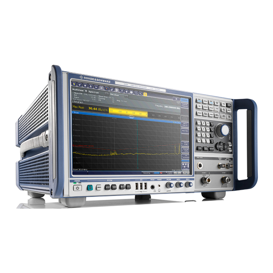
® Instrument Tour R&S The Front Panel Instrument Tour On the instrument tour, you can learn about the different control elements and connectors on the front and back panel of the R&S ESW. The Front Panel The front panel contains the main control elements of the R&S ESW in addition to various connectors as shown in Figure 5-1. -
Page 41: Display (Touchscreen)
® Instrument Tour R&S The Front Panel Instrument damage caused by cleaning agents Cleaning agents contain substances such as solvents (thinners, acetone, etc.), acids, bases, or other substances. Solvents can damage the front panel labeling, plastic parts, or screens, for example. Never use cleaning agents to clean the outside of the instrument. - Page 42 ® Instrument Tour R&S The Front Panel 1 = Toolbar: contains general functionality of the firmware (print, save etc.). 2 = Channel tabs: each tab contains a measurement channel. 3 = Channel bar: shows measurement settings and allows you to change those settings easily. 4 = Input field.
-
Page 43: Power Key
® Instrument Tour R&S The Front Panel ● Saving or printing results and settings To imitate a right-click by mouse using the touchscreen, for example to open a context-sensitive menu for a specific item, press the screen for about 1 second. 5.1.2 Power Key The Power key on the front panel turns the instrument on and off. -
Page 44: Usb Ports
® Instrument Tour R&S The Front Panel Turns full screen mode on and off. Selects a window in split screen mode or browses through active windows in full screen mode. 5.1.4 USB Ports The three USB ports on the front panel (type A) allow you to connect devices like keyboards, mouses or memory sticks. -
Page 45: Fast Access Knobs
® Instrument Tour R&S The Front Panel Muting sound You can turn the volume on and off easily by pressing the volume control. Risk of hearing damage Before putting on the headphones, make sure that the volume setting is not too high to protect your hearing. -
Page 46: Trigger Input And Output
® Instrument Tour R&S The Front Panel Risk of instrument damage Do not overload the RF input. For maximum allowed values, see the data sheet. For AC-coupling, a DC input voltage of 50 V must never be exceeded. For DC-coupling, DC voltage must not be applied at the input. In both cases, noncompliance will destroy the input mixers. - Page 47 ® Instrument Tour R&S The Front Panel In addition to the rotary knob and the cursor keys, the navigation control also pro- vides undo / redo functionality. Rotary knob The rotary knob allows you to do several things: ● It increases or decreases any kind of numeric value. In most cases, the rotary knob changes numeric values with a fixed step size.
-
Page 48: The Keypad
® Instrument Tour R&S The Front Panel Undo and redo functionality Reverts the software to an older state by erasing the last change you have applied. The undo function is useful, for example, if you are performing a measure- ment with several markers and a limit line and accidentally select a different measurement. -
Page 49: 5.1.12 The Function Keys
® Instrument Tour R&S The Front Panel Provides the following functions: In dialog boxes: ● Closes all kinds of dialog boxes if edit mode is not active. ● Quits edit mode if it is active. ● Selects the "Cancel" button when available. In "Edit"... - Page 50 ® Instrument Tour R&S The Front Panel Provides functionality to define various filter bandwidths. Provides functionality to configure the measurement, for example: ● the measurement mode (single or continuous measurements) ● the number of measurement points ● the measurement time Provides functionality to configure data acquisition and analyze measured data, for example: ●...
-
Page 51: The Rear Panel
® Instrument Tour R&S The Rear Panel Provides functionality to configure inputs and outputs. Starts a measurement in single measurement mode. Starts a measurement in continuous measurement mode. The Rear Panel The rear panel contains various connectors as shown in Figure 5-2. -
Page 52: Removable Hard Disk
® Instrument Tour R&S The Rear Panel = GPIB interface = OCXO external reference (option R&S ESW-B4) = REF inputs and outputs Not shown = External Generator control (option R&S ESW-B10) ● Removable Hard Disk..................52 ● AC Power Connector and Main Power Switch..........52 ●... -
Page 53: Displayport And Dvi
® Instrument Tour R&S The Rear Panel 5.2.3 DisplayPort and DVI You can connect an external monitor or other display device to the R&S ESW. Another display device allows you to view the user interface on a bigger screen. Two different types of connectors are provided for this purpose: ●... -
Page 54: Sync Trigger Input And Output
® Instrument Tour R&S The Rear Panel 5.2.7 Sync Trigger Input and Output The "Sync Trigger Input / Output" connectors allow you to synchronize several devices (for example two R&S ESWs) with respect to the trigger signal, but also the reference frequency. A 100 MHz signal can be output as a trigger or reference signal to another device, and an external trigger or reference signal can be received at the input connector by the R&S ESW. -
Page 55: Gpib Interface
® Instrument Tour R&S The Rear Panel 5.2.9 GPIB Interface The GPIB interface is in compliance with IEEE488 and SCPI. A computer for remote control can be connected via this interface. To set up the connection, a shielded cable is recommended. For more details refer to "Setting Up Remote Control"... - Page 56 ® Instrument Tour R&S The Rear Panel The REF OUTPUT connectors can be used to provide an external reference sig- nal (or the optional OCXO reference signal) from the R&S ESW to other devices that are connected to this instrument. Various connectors are provided for different reference signals: Connector Reference signal...
-
Page 57: Operating The Instrument
® Operating the Instrument R&S Understanding the Display Information Operating the Instrument The following topics provide an overview on how to work with the R&S ESW. They describe what kind of information is displayed in the diagram area, how to interact with the R&S ESW, and how to use the online help. -
Page 58: Channel Bar
® Operating the Instrument R&S Understanding the Display Information 1 = Channel bar: shows firmware and measurement settings 2 = Window title bar: shows diagram-specific (trace) information 3 = Diagram area: contains the measurement results and other information related to the mea- surement (marker etc.) 4 = Diagram footer: shows diagram-specific information, depending on measurement application 5 = Instrument status bar: shows error messages, measurement progress, date/time etc. - Page 59 ® Operating the Instrument R&S Understanding the Display Information nel bar with an additional button. Tap this button to switch to the corresponding channel display quickly. Icons in the channel bar The star icon ( ) on the tab label indicates that the displayed trace no longer matches the current instrument settings.
- Page 60 ® Operating the Instrument R&S Understanding the Display Information Label Information "Step" Currently selected scan type and frequency step mode. ● "LIN": Stepped scan with linear frequency steps. The frequency step size is a fix value in Hz. ● "LOG": Stepped scan with logarithmic fre- quency steps.
-
Page 61: Window Title Bar
® Operating the Instrument R&S Understanding the Display Information valid and the measurement is correct. A red bullet indicates an invalid setting that does not provide useful results. 6.1.2 Window Title Bar Each channel in the R&S ESW display can contain several windows. Each win- dow can display either a graph or a table as a result of the channel measurement. -
Page 62: Marker Information
® Operating the Instrument R&S Understanding the Display Information Trace Mode Abbreviation of the trace mode: ● Clrw Clear Write: Shows the currently measured values. ● Max Hold: Shows the maximum values that have been measured. ● Min Hold: Shows the minimum values that have been measured. ●... -
Page 63: Frequency And Span Information In Diagram Footer
® Operating the Instrument R&S Understanding the Display Information Label Information "X-value" x-value of the marker "Y-value" y-value of the marker 6.1.4 Frequency and Span Information in Diagram Footer The information in the diagram footer (beneath the diagram) depends on the cur- rent application. - Page 64 ® Operating the Instrument R&S Understanding the Display Information Instrument status The R&S ESW is configured for operation with an external reference. Selecting the "Ext Ref" icon opens a dialog box to configure the exter- nal reference. The status of an LXI connection (green label = connection established, red label = connection not established) Selecting the "LXI"...
-
Page 65: Error Information
® Operating the Instrument R&S Understanding the Display Information 6.1.6 Error Information If errors or irregularities are detected, a keyword and an error message, if availa- ble, are displayed in the status bar. Depending on the type of message, the status message is indicated in varying colors. -
Page 66: Accessing Functions
® Operating the Instrument R&S Accessing Functions Accessing Functions All tasks necessary to operate the instrument can be performed using the user interface. Apart from instrument specific keys, all other keys that correspond to an external keyboard (for example arrow keys, [Enter] key) operate conform to Microsoft. - Page 67 ® Operating the Instrument R&S Accessing Functions Windows: opens the Windows "Start" menu and task bar. Open: opens a file from the instrument or an external device ("Save/Recall" menu). Store: stores data on the instrument or an external device ("Save/Recall" menu).
-
Page 68: Softkeys
® Operating the Instrument R&S Accessing Functions Create report: creates a new measurement report and deletes previous report data. Create report: creates a new measurement report without deleting previous report data. RF input off: Signal applied to the RF input is not measured (instead the sig- nal path of the calibration signal is used). -
Page 69: Context Menus
® Operating the Instrument R&S Accessing Functions You can hide the softkey display, e.g. when using remote control, in order to enlarge the display area for the measurement results ("Setup > Display > Displayed Items"). See the User Manual for details. 6.2.3 Context Menus Several items in the diagram area have context-sensitive menus (for example... -
Page 70: Changing The Focus
® Operating the Instrument R&S Changing the Focus The on-screen keyboard display can be switched on and off as desired using the "On-Screen Keyboard" function key beneath the screen. When you press this key, the display switches between the following options: ●... -
Page 71: Entering Data
® Operating the Instrument R&S Entering Data Entering Data You can enter data in dialog boxes using any of the following methods: ● Using the touchscreen, via the on-screen keyboard ● Using other elements provided by the front panel, e.g. the keypad, rotary knob, or navigation keys The rotary knob acts like the [ENTER] key when it is pressed. -
Page 72: Entering Alphanumeric Parameters
® Operating the Instrument R&S Entering Data 3. If the parameter does not require a unit, confirm the entered value by pressing the [ENTER] key or any of the unit keys. The editing line is highlighted to confirm the entry. 6.4.2 Entering Alphanumeric Parameters If a field requires alphanumeric input, you can use the on-screen keyboard to... - Page 73 ® Operating the Instrument R&S Entering Data To correct an entry 1. Using the arrow keys, move the cursor to the right of the entry you want to delete. 2. Press the [BACKSPACE] key. The entry to the left of the cursor is deleted. 3.
-
Page 74: Displaying Results
® Operating the Instrument R&S Displaying Results Displaying Results The R&S ESW provides several instrument applications for different analysis tasks and different types of signals, for example the Receiver application, the Spectrum application or the I/Q Analyzer. For each application, a new measure- ment channel is created and displayed in a separate tab on the screen. - Page 75 ® Operating the Instrument R&S Displaying Results To start a new channel 1. Select the [Mode] key. 2. In the "Mode" dialog box, select the required application on the "New Chan- nel" tab. A new tab is displayed for the new channel. To change the application in an active channel 1.
-
Page 76: Laying Out The Result Display With The Smartgrid
® Operating the Instrument R&S Displaying Results Select the "Close" icon on the tab of the measurement channel. The tab is closed, any running measurements are aborted, and all results for that channel are deleted. 6.5.2 Laying out the Result Display with the SmartGrid Measurement results can be evaluated in many different ways, for example graphically, as summary tables, statistical evaluations etc. -
Page 77: Background Information: The Smartgrid Principle
® Operating the Instrument R&S Displaying Results ● Background Information: The SmartGrid Principle..........77 ● How to Activate SmartGrid Mode..............78 ● How to Add a New Result Window..............79 ● How to Close a Result Window...............79 ● How to Arrange the Result Windows.............. -
Page 78: How To Activate Smartgrid Mode
® Operating the Instrument R&S Displaying Results Positioning the window The screen can be divided into up to four rows. Each row can be split into up to four columns, where each row can have a different number of columns. However, rows always span the entire width of the screen and may not be interrupted by a column. -
Page 79: How To Add A New Result Window
® Operating the Instrument R&S Displaying Results ● Select the "SmartGrid" icon from the toolbar. ● Select the "Display Config" button in the configuration "Overview". ● Select the "Display Config" softkey from the [MEAS CONFIG] menu. The SmartGrid functions and the evaluation bar are displayed. To close the SmartGrid mode and restore the previous softkey menu select the "Close"... -
Page 80: Changing The Size Of Windows
® Operating the Instrument R&S Displaying Results 6.5.2.5 How to Arrange the Result Windows 1. Select an icon from the evaluation bar or the "Move" icon for an existing eval- uation window. 2. Drag the evaluation over the SmartGrid. A blue area shows where the window will be placed. 3. -
Page 81: Switching Between A Split And Maximized Window Display
® Operating the Instrument R&S Displaying Results The splitters are not available in SmartGrid mode. ► To change the size of two neighboring windows, drag the splitter between the windows in either direction. 6.5.4 Switching Between a Split and Maximized Window Dis- play To get an overview of the results, displaying several windows at the same time may be helpful. -
Page 82: Changing The Display
® Operating the Instrument R&S Getting Help Alternatively, double-tap the title bar of a window to maximize it. 6.5.5 Changing the Display The display can be optimized for your individual needs. The following display functions are available and are described in detail in the User Manual. ●... -
Page 83: Using The Help Window
® Operating the Instrument R&S Getting Help The "Help" dialog box "View" tab is displayed. A topic containing information about the focused screen element is displayed. If no context-specific help topic is available, a more general topic or the "Con- tent"... - Page 84 ® Operating the Instrument R&S Getting Help To navigate the Help, use the touchscreen. Alternatively, you can also use the navigation keys on the front panel. To search for a topic in the index The index is sorted alphabetically. You can browse the list, or search for entries in the list.
-
Page 85: Remote Control
® Operating the Instrument R&S Remote Control Remote Control In addition to working with the R&S ESW interactively, located directly at the instrument, it is also possible to operate and control it from a remote PC. Various methods for remote control are supported: ●... -
Page 86: Remote Desktop Connection
® Operating the Instrument R&S Remote Control 6.7.2 Remote Desktop Connection Remote Desktop is a Windows application which can be used to access and con- trol the instrument from a remote computer through a LAN connection. While the instrument is in operation, the instrument screen contents are displayed on the remote computer. -
Page 87: Collecting Information For Support
® Collecting Information for Support R&S Collecting Information for Support If problems occur, the instrument generates error messages which in most cases will be sufficient for you to detect the cause of an error and find a remedy. Error messages are described in the "Troubleshooting" section of the user man- uals. - Page 88 ® Collecting Information for Support R&S The file is stored as C:\Program Files (x86)\Rohde-Schwarz\ESW\<version>\user\ <inst_model>_<serial-no>_<date_and_time>.zip The file is stored as C:\Program Files (x86)\Rohde-Schwarz\ESW\<version>\user\ ESW_*.zip. To create Windows event log files 1. Select the "Windows Start Button" in the bottom left corner. 2.
- Page 89 ® Collecting Information for Support R&S Packing and transporting the instrument If the instrument needs to be transported or shipped, observe the notes described in Chapter 4.1.1, "Unpacking and Checking the Instrument", on page 15. Getting Started 1328.4922.02 ─ 06...
-
Page 90: Index
® Index R&S Index Symbols REF INPUT ......... 55 USB ............ 53 75 Ω (channel bar) ........60 Connectors External generators ......55 OCXO ..........55 AC (trace information) ......61 SYNC TRIGGER ........ 54 Alphanumeric keys ........48 Trigger Input ........46 Alphanumeric parameters ....... - Page 91 ® Index R&S Error messages IF/VIDEO/DEMOD see User Manual .........65 Connector ........... 53 Status bar ........... 65 Input (channel bar) ........59 ESD ............14 IP address Evaluation Changing ..........31 Modes, adding ........79 Evaluation bar Using ...........79 EXT REF Power ..........43 Status message ........
- Page 92 ® Index R&S Mini Front Panel Release notes ......... 10 Displaying - see User Manual ..... 82 Remote control ........86 MultiView Configuration - see user Manual ..85 Status display ........63 Introduction - see user Manual ... 85 Remote Desktop see User Manual .........86 Removable hard drive ......
- Page 93 ® Index R&S Splitters Volatile memory Window size ........80 Secure user mode ......36 Status bar Volume control .........44 Color coding ........65 Error messages ........65 Secure user mode ......38 White papers ........... 10 Status display .......... 63 Window title bar ........61 Step (channel bar) ........
Need help?
Do you have a question about the ESW EMI and is the answer not in the manual?
Questions and answers