Sign In
Upload
Manuals
Brands
Juniper Manuals
Network Router
M120
Juniper M120 Manuals
Manuals and User Guides for Juniper M120. We have
3
Juniper M120 manuals available for free PDF download: Hardware Manual, Pic Manual
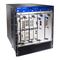
Juniper M120 Hardware Manual (382 pages)
Multiservice Edge Router
Brand:
Juniper
| Category:
Network Router
| Size: 9.35 MB
Table of Contents
Table of Contents
3
About the Documentation
21
Documentation and Release Notes
21
Documentation Conventions
21
Table 1: Notice Icons
22
Table 2: Text and Syntax Conventions
22
Documentation Feedback
23
About the Documentation
23
Requesting Technical Support
24
Self-Help Online Tools and Resources
24
Opening a Case with JTAC
24
Overview
27
Chassis Components and Descriptions
27
Cooling System Components and Descriptions
27
Line Card Components and Descriptions
27
Power System Components and Descriptions
27
Switch Fabric Components and Descriptions
27
Chapter 1 System Overview
29
M120 Router Description
29
M120 Component Redundancy
30
Chapter 2 M120 Router Release Notes
31
Outstanding Issues with the M120 Router
31
Errata with the M120 Router Documentation
31
Chapter 3 Chassis Components and Descriptions
33
M120 Router Chassis Description
33
Figure 1: Front View of a Fully Configured M120 Router Chassis
34
Figure 2: Rear View of a Fully Configured AC-Powered M120 Router Chassis
34
M120 Midplane Description
35
Figure 3: Rear View of a Fully Configured DC-Powered M120 Router Chassis
35
M120 Cable Management System Description
36
Figure 4: M120 Midplane
36
M120 Craft Interface Description
37
Craft Interface Front Panel
37
Figure 5: M120 Cable Management System
37
Figure 6: Front Panel of the M120 Craft Interface
37
M120 Alarm Relay Contacts on the Craft Interface
38
M120 External Clock Interface Ports on the Craft Interface
38
M120 Routing Engine Interface Ports and Status Indicators
38
M120 Alarm Leds and Alarm Cutoff/Lamp Test Button
39
Table 3: M120 Alarm Leds and Alarm Cutoff/Lamp Test Button
39
M120 Component Leds on the Craft Interface
40
Host Subsystem Leds on the M120 Craft Interface
40
Ethernet Port Leds on the Craft Interface
40
Table 4: M120 Host Subsystem Leds
40
FEB Leds on the M120 Craft Interface
41
FPC Leds on the M120 Craft Interface
41
Power Supply Leds on the M120 Craft Interface
41
External Clocking Inputs Leds on the M120 Craft Interface
41
Table 5: FEB Leds on the M120 Craft Interface
41
Table 6: M120 FPC Leds
41
Table 7: Power Supply Leds on the M120 Craft Interface
41
M120 External Clock Interface Ports on the Craft Interface
42
Table 8: External Clock Leds on the M120 Craft Interface
42
M120 Alarm Relay Contacts on the Craft Interface
43
Chapter 4 Cooling System Components and Descriptions
45
M120 Cooling System Description
45
Figure 7: Airflow through the M120 Chassis
46
Figure 8: M120 Front Fan Tray
46
Figure 9: M120 Rear Fan Tray
46
Chapter 5 Host Subsystem Components and Descriptions
47
M120 Host Subsystem Description
47
M120 Routing Engine Description
48
Figure 10: M120 Routing Engine
48
Figure 11: RE-A-1800X2 Routing Engine
49
Routing Engine Components
49
Figure 12: USB Memory Device in an M120 Routing Engine
50
Routing Engine Boot Sequence
50
M120 Routing Engine Leds
51
M120 RE-A-1800X2 Routing Engine Description
51
Routing Engine Components
51
Table 9: M120 Routing Engine LED
51
Figure 13: RE-A-1800X2 Routing Engine
52
Routing Engine Boot Sequence
53
RE-A-1800 Routing Engine Leds
53
Figure 14: USB Memory Device in an Routing Engine
53
M120 Routing Engine Interface Ports and Status Indicators
54
Table 10: Routing Engine Leds
54
Routing Engine Specifications
55
Table 11: Routing Engine Specifications
55
Table 12: End-Of-Life Routing Engine Specifications
58
Supported Routing Engines by Router
59
M7I Routing Engines
60
M10I Routing Engines
60
M40E Routing Engines
60
Table 13: M7I Routing Engines
60
Table 14: M10I Routing Engines
60
M120 Routing Engines
61
M320 Routing Engines
61
Table 15: M40E Routing Engines
61
Table 16: M120 Routing Engines
61
MX5, MX10, MX40, and MX80 Routing Engine
62
MX104 Routing Engines
62
Table 17: M320 Routing Engines
62
Table 18: MX5, MX10, MX40, and MX80 Routing Engine
62
MX240 Routing Engines
63
Table 19: MX104 Routing Engines
63
Table 20: MX240 Supported Routing Engines
63
MX480 Routing Engines
64
Table 21: MX480 Supported Routing Engines
64
MX960 Routing Engines
65
MX2008 Routing Engines
65
Table 22: MX960 Supported Routing Engines
65
MX2010 Routing Engines
66
MX2020 Supported Routing Engines
66
Table 23: MX2008 Supported Routing Engines
66
Table 24: MX2010 Supported Routing Engines
66
Table 25: MX2020 Supported Routing Engines
66
MX10003 Routing Engines
67
PTX1000 Routing Engines
67
Table 26: MX10003 Supported Routing Engines
67
Table 27: PTX1000 Routing Engines
67
PTX3000 Routing Engines
68
PTX5000 Routing Engines
68
Table 28: PTX3000 Routing Engines
68
PTX10008 and PTX10016 Routing Engines
69
T320 Routing Engines
69
Table 29: PTX5000 Routing Engines
69
Table 30: PTX10008 and PTX10016 Routing Engines
69
Table 31: T320 Routing Engines
69
T640 Routing Engines
70
Table 32: T640 Routing Engines
70
T1600 Routing Engines
71
T4000 Routing Engines
71
Table 33: T1600 Routing Engines
71
TX Matrix Routing Engines
72
TX Matrix Plus Routing Engines
72
Table 34: T4000 Routing Engines
72
Table 35: TX Matrix Routing Engines
72
TX Matrix Plus (with 3D Sibs) Routing Engines
73
M120 Control Board (CB) Description
73
Table 36: TX Matrix Plus Routing Engines
73
Table 37: Routing Engines on TX Matrix Plus with 3D Sibs
73
CB Components
74
M120 Control Board (CB) Leds
74
Figure 15: M120 CB
74
Table 38: M120 Control Board Leds
75
Chapter 6 Line Card Components and Descriptions
77
M120 Flexible PIC Concentrators (Fpcs) Description
77
Figure 16: FPC and Cfpcs Installed in an M120 Router Chassis
78
Figure 17: FPC1, FPC2, and FPC3 for the M120 Router
79
FPC Components
79
FPC Terminology
79
Line Card Components and Descriptions
79
M120 Flexible PIC Concentrators (Fpcs) LED
80
M120 Compact Fpcs (Cfpcs) Description
80
Figure 18: FPC and Cfpcs Installed in an M120 Router Chassis
81
Figure 19: Ethernet 10GBASE XFP CFPC for the M120 Router
81
CFPC Components
82
M120 Fpcs and Cfpcs Supported
82
Table 39: Fpcs Supported by the M120 Router
82
M120 Pics Description
83
Table 40: Cfpcs Supported by the M120 Router
83
M120 PIC Leds
84
M120 Pics Supported
84
Table 41: Pics Supported in the M120 Router
84
M120 End-Of-Life Pics Supported
89
Table 42: End-Of-Life Pics Supported in the M120 Router
89
M120 PIC/FPC Compatibility
92
Table 43: M120 PIC/FPC Compatibility
92
Chapter 7 Power System Components and Descriptions
97
M120 Power Supplies Description
97
M120 DC Power Supply Description
98
M120 AC Power Supply Description
98
Figure 20: M120 DC Power Supply
98
M120 Power Supply Leds
99
Figure 21: M120 AC Power Supply
99
Power System Components and Descriptions
99
Table 44: M120 Power Supply LED
100
Chapter 8 Switch Fabric Components and Descriptions
101
M120 Forwarding Engine Boards (Febs) Description
101
FEB Components
102
Figure 22: M120 FEB
102
M120 Forwarding Engine Boards (Febs) Leds
103
Table 45: M120 FEB Leds
103
AC Power Requirements and Specifications
105
DC Power Requirements and Specifications
105
Chapter 9 Preparation Overview
105
Site Planning, Preparation, and Specifications
105
Preparation Overview
107
M120 Site Preparation Checklist
107
Cabinet
107
Table 46: M120 Site Preparation Checklist
107
M120 Router Physical Specifications
108
M120 Cabinet Size and Clearance Requirements
108
Table 47: M120 Physical Specifications
108
M120 Cabinet Airflow Requirements
109
M120 Rack Mounting Requirements
109
Table 48: M120 Rack Requirements and Specifications
110
M120 Clearance Requirements for Airflow and Hardware Maintenance
111
Figure 23: Typical Open-Frame Rack
111
M120 Router Environmental Specifications
112
Figure 24: M120 Chassis Dimensions and Clearance Requirements
112
Table 49: M120 Router Environmental Specifications
112
M120 Chassis Grounding Specifications
113
M120 Router Power Requirements
114
Figure 25: M120 DC Power and Grounding Cable Lug
114
Table 50: Power System Electrical Specifications
114
Table 51: AC Power Supply Electrical Specifications
115
Table 52: DC Power Supply Electrical Specifications
115
Table 53: Component Power Requirements
115
Chapter 10 AC Power Requirements and Specifications
119
M120 AC Power, Connection, and Power Cord Specifications
119
Table 54: AC Power Cord Specifications
120
Electrical Specifications for the M120 AC Power Supply
121
Figure 26: M120 AC Plug Types
121
Table 55: AC Power Supply Electrical Specifications
122
Chapter 11 DC Power Requirements and Specifications
123
M120 DC Power, Connection, and Cable Specifications
123
Figure 27: Typical DC Source Cabling to the M120 Router
124
DC Power Requirements and Specifications
125
Table 56: M120 DC Power and Grounding Cable Specifications
125
Electrical Specifications for the M120 DC Power Supply
126
Table 57: DC Power Supply Electrical Specifications
126
Chapter 12 Network Cable and Transceiver Planning
127
Understanding Fiber-Optic Cable Signal Loss, Attenuation, and Dispersion
127
Signal Loss in Multimode and Single-Mode Fiber-Optic Cable
127
Attenuation and Dispersion in Fiber-Optic Cable
127
Calculating Power Budget and Power Margin for Fiber-Optic Cables
128
Calculating Power Budget for Fiber-Optic Cable
128
Calculating Power Margin for Fiber-Optic Cable
129
Network Cable and Transceiver Planning
129
Table 58: Estimated Values for Factors Causing Link Loss
129
Chapter 13 Management Cable and Transceiver Specifications and Pinouts
131
Routing Engine Interface Cable and Wire Specifications for the M120 Router
131
Table 59: Routing Engine Interface Cable and Wire Specifications
131
RJ-45 Connector Pinouts for the M120 Routing Engine ETHERNET Port
132
RJ-45 Connector Pinouts for the Routing Engine AUX and CONSOLE Ports
132
Table 60: RJ-45 Connector Pinout for the Routing Engine ETHERNET Port
132
Table 61: RJ-45 Connector Pinout for the Routing Engine AUX and CONSOLE
132
RJ-45 Connector Pinouts for the External Clock Ports
133
Management Cable and Transceiver Specifications and Pinouts
133
Table 62: RJ-45 Connector Pinout for the External Interface Ports
133
Initial Installation and Configuration
135
Installing the M120 with a Mechanical Lift
135
Installing the Mounting Hardware
135
Unpacking the M120
135
Chapter 14 Installation Overview
137
M120 Router Installation Summary
137
Chapter 15 Unpacking the M120
139
Tools and Parts Required to Unpack the M120 Router
139
Unpacking the M120 Router
139
Verifying M120 Parts Received
141
Figure 28: Contents of the M120 Shipping Container
141
Table 63: Parts List for a Fully Configured M120 Router
141
Table 64: Accessory Box Parts List
142
Chapter 16 Installing the Mounting Hardware
145
Cabinet
145
Table 65: Four-Post Rack or Cabinet Mounting Hole Locations for the M120
145
Installing the Mounting Hardware for a Front-Mount Open-Frame Rack
147
Figure 29: Installing the M120 Mounting Hardware for a Four-Post Rack or
147
Table 66: Open-Frame Rack Mounting Hole Locations for the M120 Router
147
Installing the Mounting Hardware for a Center-Mount Open-Frame Rack
149
Figure 30: Installing the M120 Mounting Hardware for an Open-Frame Rack
149
Chapter 17 Installing the M120 with a Mechanical Lift
151
Tools Required to Install the M120 Router Using a Mechanical Lift
151
Installing the M120 Router Using a Mechanical Lift
151
Figure 31: Installing the M120 Router in the Rack
153
Chapter 18 Installing the M120 Without a Mechanical Lift
155
Lift
155
Removing Components from the Chassis before Installing the M120 Router Without a Mechanical Lift
155
Removing the Power Supplies
156
Removing Febs
157
Installing the M120 Without a Mechanical Lift
157
Figure 32: Removing a Power Supply before Installing the M120 Router
157
Removing Cbs
158
Figure 33: Removing a FEB before Installing the M120 Router
158
Removing a Fan Tray
159
Figure 34: Removing a CB before Installing the M120 Router
159
Figure 35: Removing an Upper Front Fan Tray before Installing the M120
160
Removing the Cable Management System
161
Figure 36: Removing a Lower Rear Fan Tray before Installing the M120
161
Removing Fpcs
162
Figure 37: Removing the Cable Management System before Installing the M120
162
Removing a CFPC
163
Figure 38: Removing an FPC before Installing the M120 Router
163
Figure 39: Removing a CFPC before Installing the M120 Router
164
Installing the M120 Router Without Using a Mechanical Lift
165
Figure 40: Installing the M120 Router in the Rack
167
Mechanical Lift
168
Reinstalling Cbs
168
Figure 41: Reinstalling a CB after Installing the M120 Router
169
Reinstalling the Febs
169
Figure 42: Reinstalling a FEB after Installing the M120 Router
170
Reinstalling the Power Supplies
170
Figure 43: Reinstalling a Power Supply after Installing the M120 Router
171
Reinstalling Fpcs
171
Figure 44: Reinstalling an FPC after Installing the M120 Router
172
Reinstalling a CFPC
172
Figure 45: Reinstalling a CFPC after Installing the M120 Router
174
Reinstalling the Fan Trays
174
Figure 46: Reinstalling a Front Fan Tray after Installing the M120 Router
175
Reinstalling the Cable Management System
175
Chapter 19 Connecting the M120 to Ground
177
Connecting the Grounding Cable to the M120 Router
177
Figure 47: Connecting the Grounding Cable to the M120 Router
178
Chapter 20 Connecting the M120 to External Devices
179
Tools and Parts Required to Connect the M120 Router
179
Connecting the M120 Router to Management and Alarm Devices
179
Device
179
Figure 48: M120 Routing Engine Management Ports and Alarm Relay
180
Figure 49: M120 Console and Auxiliary Serial Port Connector
181
Connecting the M120 Router to a Network for Out-Of-Band Management
182
Figure 50: M120 Routing Engine Management Ports and Alarm Relay
182
Figure 51: M120 Routing Engine Ethernet Cable Connector
183
Figure 52: M120 Routing Engine External Device Ports
183
Connecting the M120 Router to an External Alarm-Reporting Device
184
Figure 53: M120 Routing Engine Alarm Relay Contacts
185
Connecting the M120 Router to a Network for Out-Of-Band Management
186
Figure 54: M120 Routing Engine Ethernet Cable Connector
186
Connecting the M120 Router to an External Alarm-Reporting Device
187
Figure 55: M120 Routing Engine External Device Ports
187
Connecting the M120 Router to an External Clocking Device
189
Figure 56: M120 Routing Engine Alarm Relay Contacts
189
Connecting PIC Cables to the M120 Router
190
Figure 57: Attaching a Cable to an M120 PIC
192
Chapter 21 Providing Power to the M120
193
Connecting Power to an AC-Powered M120 Router
193
Figure 58: Connecting AC Power to the M120 Router
194
Connecting Power to a DC-Powered M120 Router
195
Powering on the M120 Router
196
Figure 59: Connecting DC Power to the M120 Router
196
Powering off the M120 Router
197
Chapter 22 Configuring the Junos Software
199
Initially Configuring Junos os on the M120 Router
199
Chapter 23 Installing and Replacing Components
203
Overview of Installing and Replacing Components
205
M120 Field-Replaceable Units (Frus)
205
Tools and Parts Required to Replace M120 Components
206
Table 67: M120 Field-Replaceable Units
206
Table 68: Tools and Parts Required
206
Chapter 24 Replacing Chassis Components
209
Replacing Alarm Relay Wires on the M120 Craft Interface
209
Replacing the M120 Craft Interface
210
Removing the M120 Craft Interface
210
Figure 60: M120 Routing Engine Interface Ports and Alarm Relay Contacts
210
Installing the M120 Craft Interface
211
Figure 61: Removing the M120 Craft Interface
212
Figure 62: Installing the M120 Craft Interface
212
Chapter 25 Replacing Cooling System Components
213
Replacing an M120 Air Filter
213
Removing the M120 Air Filter
213
Installing the M120 Air Filter
214
Figure 63: Removing the M120 Air Filter
214
Figure 64: Installing the M120 Front Air Filter
215
Replacing an M120 Fan Tray
216
Removing an M120 Fan Tray
216
Figure 65: Removing an M120 Upper Front Fan Tray
217
Figure 66: Removing an M120 Lower Rear Fan Tray
217
Installing an M120 Fan Tray
218
Figure 67: Installing an M120 Upper Front Fan Tray
218
Figure 68: Installing an M120 Lower Rear Fan Tray
219
Chapter 26 Replacing Host Subsystem Components
221
Replacing an M120 Routing Engine
221
Removing an M120 Routing Engine
221
Installing an M120 Routing Engine
223
Figure 69: Removing an M120 Routing Engine
223
Replacing an SSD Drive on an RE-A-1800 or RE-S-1800
224
Figure 70: Installing an M120 Routing Engine
224
Figure 71: RE-A-1800 Storage Drive Slots
225
Figure 72: RE-S-1800 Storage Drive Slots
225
Replacing a DIMM Module in M120 Routing Engines
226
Removing a M120 DIMM Module
226
Installing a M120 DIMM Module
227
Replacing an M120 CB
228
Removing an M120 CB
228
Figure 73: Installing the DIMM Module
228
Installing an M120 CB
230
Figure 74: Removing an M120 CB
230
Figure 75: Installing an M120 CB
231
Replacing Connections to M120 Routing Engine Interface Ports
232
Replacing the Management Ethernet Cable on the M120 Routing Engine
232
Figure 77: M120 Ethernet Cable Connectors
232
Replacing the Console or Auxiliary Cable on the M120 Routing Engine
233
Figure 76: M120 Routing Engine Interface Ports and Alarm Relay Contacts
233
Replacing Alarm Relay Wires on the M120 Craft Interface
234
Figure 79: M120 Routing Engine Interface Ports and Alarm Relay Contacts
234
Replacing the Console or Auxiliary Cable on the M120 Routing Engine
235
Figure 78: M120 Routing Engine Interface Ports and Alarm Relay Contacts
235
Figure 80: M120 Routing Engine Interface Ports and Alarm Relay Contacts
235
Replacing the Management Ethernet Cable on the M120 Routing Engine
236
Figure 81: M120 Routing Engine Interface Ports and Alarm Relay Contacts
236
Figure 82: M120 Ethernet Cable Connectors
237
Figure 83: M120 Routing Engine Interface Ports and Alarm Relay Contacts
237
Chapter 27 Replacing Line Card Components
239
Replacing an M120 FPC
239
Removing an M120 FPC
239
Figure 84: Removing an M120 FPC
241
Installing an M120 FPC
242
Figure 85: Installing an M120 FPC
244
Figure 86: Connecting Fiber-Optic Cable to an M120 PIC
244
Replacing an M120 CFPC
245
Removing an M120 CFPC
245
Figure 87: Removing an M120 CFPC
246
Installing an M120 CFPC
247
Figure 88: Installing an M120 CFPC
248
Replacing an M120 PIC
249
Removing an M120 PIC
249
Installing an M120 PIC
251
Figure 89: Removing an M120 PIC
251
Figure 90: Installing an M120 PIC
253
Replacing an M120 PIC Cable
254
Removing an M120 PIC Cable
254
Installing an M120 PIC Cable
255
Figure 91: Connecting Fiber-Optic Cable to an M120 PIC
256
Replacing an M120 XENPAK Module
257
Removing an M120 XENPAK Module
257
Installing an M120 XENPAK Module
258
Figure 92: Removing a M120 XENPAK Module
258
Replacing an SFP or XFP Transceiver
260
Removing an SFP or XFP Transceiver
260
Figure 93: Installing a M120 XENPAK Module
260
Installing an SFP or XFP Transceiver
262
Figure 94: Removing M120 Sfps or Xfps
262
Chapter 28 Replacing Power System Components
265
Replacing an M120 AC Power Supply
265
Removing an M120 AC Power Supply
265
Figure 95: Removing an M120 AC Power Supply
267
Figure 96: Rear of the M120 Power Supply Showing Midplane Connector
267
Installing an M120 AC Power Supply
268
Figure 97: Installing an M120 AC Power Supply
269
Replacing an M120 AC Power Supply Cord
270
Replacing an M120 DC Power Supply
271
Removing an M120 DC Power Supply
271
Figure 98: Disconnecting Power Cables from the M120 DC Power Supply
272
Installing an M120 DC Power Supply
274
Figure 99: Removing an M120 DC Power Supply
274
Figure 100: Installing an M120 DC Power Supply
276
Replacing an M120 DC Power Supply Cable
277
Figure 101: Connecting Power Cables to the M120 DC Power Supply
277
Chapter 29 Replacing Switch Fabric Components
281
Replacing an M120 FEB
281
Removing an M120 FEB
281
Installing an M120 FEB
282
Figure 102: Removing an M120 FEB
282
Figure 103: Installing an M120 FEB
283
Maintaining the Chassis and Components
285
Chapter 30 Routine Maintenance Procedures
287
Routine Maintenance Procedures on the M120 Router
287
Chapter 31 Maintaining Components and Cables
289
Tools and Parts Required to Maintain M120 Hardware Components
289
Maintaining the M120 Air Filter
289
Maintaining the M120 Fan Trays
290
Maintaining the M120 Host Subsystem
292
Taking the M120 Host Subsystem Offline
293
Table 69: Effect of Taking the M120 Host Subsystem Offline
294
Maintaining M120 Fpcs and Cfpcs
296
Storing an M120 FPC
297
Holding an M120 FPC
297
Figure 104: Holding an M120 FPC Vertically
298
Figure 105: Holding an M120 FPC Horizontally
299
Figure 106: Do Not Grasp the Connector Edge
299
Figure 107: Do Not Carry an FPC with Only One Hand
300
Maintaining M120 Pics and PIC Cables
301
Figure 108: Do Not Rest the FPC on an Edge
301
Maintaining the M120 Power Supplies
303
Maintaining the M120 Febs
304
Troubleshooting Hardware
307
Chapter 32 Troubleshooting Components
309
Overview of Troubleshooting Resources for the M120 Router
309
Troubleshooting Using the Command-Line Interface
309
Troubleshooting Using the Chassis and Interface Alarm Messages
310
Troubleshooting Using the Juniper Networks Technical Assistance
310
Center
310
M120 LED Overview
310
Craft Interface Leds
310
Component Leds
311
Troubleshooting the M120 Cooling System
312
Troubleshooting M120 Fpcs and Cfpcs
313
Troubleshooting M120 Pics
314
Troubleshooting the M120 Power System
314
Troubleshooting M120 Febs
315
Or Removal
317
Contacting Customer Support and Returning the Chassis or Components
319
Advertisement
Juniper M120 Hardware Manual (306 pages)
Multiservice Edge Router
Brand:
Juniper
| Category:
Network Router
| Size: 9.22 MB
Table of Contents
Hardware Guide
1
Table of Contents
7
About the Documentation
23
Junos os Documentation and Release Notes
23
Objectives
23
Audience
24
Documentation Conventions
24
Table 1: Notice Icons
24
Table 2: Text and Syntax Conventions
24
Documentation Feedback
25
About the Documentation
25
Requesting Technical Support
26
Self-Help Online Tools and Resources
26
Opening a Case with JTAC
27
Overview of the M120 Multiservice Edge Router
29
Chapter 1 Overview of the M120 Router
31
M120 Router Description
31
Overview of the M120 Router
31
Appendix C M120 Router Environmental Specifications
32
Chapter 2 M120 Hardware Components
33
M120 Component Redundancy
33
M120 Router Chassis Description
34
M120 Hardware Components
35
Figure 1: Front View of a Fully Configured M120 Router Chassis
35
Figure 2: Rear View of a Fully Configured AC-Powered M120 Router Chassis
35
M120 Midplane Description
36
Figure 3: Rear View of a Fully Configured DC-Powered M120 Router Chassis
36
M120 Flexible PIC Concentrators (Fpcs) Overview
37
Figure 4: M120 Midplane
37
FPC Description
37
M120 Hardware Components
37
Figure 5: FPC and Cfpcs Installed in an M120 Router Chassis
38
Figure 6: FPC1, FPC2, and FPC3 for the M120 Router
39
FPC Components
39
FPC Terminology
39
M120 Compact Fpcs (Cfpcs) Overview
40
CFPC Description
40
CFPC Components
41
Figure 7: FPC and Cfpcs Installed in an M120 Router Chassis
41
Figure 8: Ethernet 10GBASE XFP CFPC for the M120 Router
41
M120 Fpcs and Cfpcs Supported
42
Table 3: Fpcs Supported by the M120 Router
42
M120 Pics Description
43
Table 4: Cfpcs Supported by the M120 Router
43
M120 Forwarding Engine Boards (Febs) Overview
44
FEB Components
44
Figure 9: M120 FEB
44
M120 Forwarding Engine Boards (Febs) Description
44
M120 Forwarding Engine Boards (Febs) Leds
45
Table 5: M120 FEB Leds
45
M120 Host Subsystem Description
46
M120 Routing Engine Overview
46
M120 Routing Engine Description
46
Figure 10: M120 Routing Engine
47
Routing Engine Components
47
Figure 11: USB Memory Device in an M120 Routing Engine
48
Routing Engine Boot Sequence
48
M120 Routing Engine Leds
49
M120 Control Board (CB) Overview
49
M120 Control Board (CB) Description
49
Table 6: M120 Routing Engine LED
49
CB Components
50
Figure 12: M120 CB
50
M120 Control Board (CB) Leds
51
M120 Craft Interface Overview
51
M120 Craft Interface Description
51
Table 7: M120 Control Board Leds
51
Figure 13: Front Panel of the M120 Craft Interface
52
Interface
52
Table 8: M120 Alarm Leds and Alarm Cutoff/Lamp Test Button
52
External Clock Interface Ports on the M120 Craft Interface
53
Interface
53
Host Subsystem Leds on the M120 Craft Interface
54
Table 10: M120 Host Subsystem Leds
54
Table 9: External Clock Leds on the M120 Craft Interface
54
FEB Leds on the M120 Craft Interface
55
FPC Leds on the M120 Craft Interface
55
Table 11: FEB Leds on the M120 Craft Interface
55
Table 12: M120 FPC Leds
55
Alarm Relay Contacts on the M120 Craft Interface
56
Power Supply Leds on the M120 Craft Interface
56
M120 Power Supplies Overview
56
Table 13: Power Supply Leds on the M120 Craft Interface
56
M120 AC Power Supply Description
57
M120 Power Supplies Description
57
Figure 14: M120 AC Power Supply
58
M120 AC Power Supply Leds
58
Table 14: M120 Power Supply LED
58
Figure 15: M120 DC Power Supply
59
M120 DC Power Supply Description
59
M120 DC Power Supply Leds
60
M120 Cooling System Description
60
Figure 16: Airflow through the M120 Chassis
61
Figure 17: M120 Front Fan Tray
61
Figure 18: M120 Rear Fan Tray
61
M120 Cable Management System Description
62
Figure 19: M120 Cable Management System
62
Preparing the Site for M120 Router Installation
63
Setting up the M120 Router
63
Chapter 3 Preparing the Site for M120 Router Installation
65
M120 Site Preparation Checklist
65
M120 Cabinet Requirements
66
Cabinet
66
M120 Cabinet Airflow Requirements
66
M120 Cabinet Size and Clearance Requirements
66
M120 Rack Mounting Requirements
67
Preparing the Site for M120 Router Installation
67
Table 16: M120 Rack Requirements and Specifications
67
M120 Clearance Requirements for Airflow and Hardware Maintenance
69
Figure 20: Typical Open-Frame Rack
69
Figure 21: M120 Chassis Dimensions and Clearance Requirements
70
Chapter 4 Unpacking the M120 Router
71
M120 Router Installation Summary
71
Tools and Parts Required to Unpack the M120 Router
72
Unpacking the M120 Router
72
Figure 22: Contents of the M120 Shipping Container
73
Verifying M120 Parts Received
74
Table 15: M120 Site Preparation Checklist
74
Table 17: Parts List for a Fully Configured M120 Router
74
Table 18: Accessory Box Parts List
75
Chapter 5 Installing the M120 Router Mounting Hardware
77
Cabinet
77
Table 19: Four-Post Rack or Cabinet Mounting Hole Locations for the M120
77
Installing the Mounting Hardware for a Front-Mount Open-Frame Rack
79
Installing the M120 Router Mounting Hardware
79
Figure 23: Installing the M120 Mounting Hardware for a Four-Post Rack or
79
Table 20: Open-Frame Rack Mounting Hole Locations for the M120 Router
80
Installing the Mounting Hardware for a Center-Mount Open-Frame Rack
81
Figure 24: Installing the M120 Mounting Hardware for an Open-Frame Rack
81
Installing the M120 Router Mounting Hardware
81
Chapter 6 Installing the M120 Router with a Lift
83
Tools Required to Install the M120 Router Using a Mechanical Lift
83
Installing the M120 Router Using a Mechanical Lift
83
Installing the M120 Router with a Lift
85
Figure 25: Installing the M120 Router in the Rack
85
Chapter 7 Installing the M120 Router Without a Mechanical Lift
87
Lift
87
Removing Components from the Chassis before Installing the M120 Router Without a Mechanical Lift
87
Removing the Power Supplies
88
Figure 26: Removing a Power Supply before Installing the M120 Router
89
Installing the M120 Router Without a Mechanical Lift
89
Removing Febs
89
Figure 27: Removing a FEB before Installing the M120 Router
90
Removing Cbs
90
Figure 28: Removing a CB before Installing the M120 Router
91
Removing a Fan Tray
91
Figure 29: Removing an Upper Front Fan Tray before Installing the M120
92
Figure 30: Removing a Lower Rear Fan Tray before Installing the M120
93
Removing the Cable Management System
93
Figure 31: Removing the Cable Management System before Installing the M120
94
Removing Fpcs
94
Figure 32: Removing an FPC before Installing the M120 Router
95
Removing a CFPC
95
Figure 33: Removing a CFPC before Installing the M120 Router
96
Installing the M120 Router Without Using a Mechanical Lift
97
Figure 34: Installing the M120 Router in the Rack
98
Mechanical Lift
99
Reinstalling Cbs
99
Figure 35: Reinstalling a CB after Installing the M120 Router
100
Reinstalling the Febs
100
Figure 36: Reinstalling a FEB after Installing the M120 Router
101
Reinstalling the Power Supplies
101
Figure 37: Reinstalling a Power Supply after Installing the M120 Router
102
Reinstalling Fpcs
102
Figure 38: Reinstalling an FPC after Installing the M120 Router
103
Reinstalling a CFPC
103
Figure 39: Reinstalling a CFPC after Installing the M120 Router
104
Figure 40: Reinstalling a Front Fan Tray after Installing the M120 Router
105
Reinstalling the Cable Management System
105
Reinstalling the Fan Trays
105
Chapter 8 Grounding the M120 Router
107
Connecting the Grounding Cable to the M120 Router
107
Figure 41: Connecting the Grounding Cable to the M120 Router
108
Chapter 9 Connecting the M120 Router to External Devices
109
Tools and Parts Required to Connect the M120 Router
109
Connecting the M120 Router to Management and Alarm Devices
109
Device
109
Figure 42: M120 Routing Engine Management Ports and Alarm Relay
110
Figure 43: M120 Console and Auxiliary Serial Port Connector
111
Connecting the M120 Router to a Network for In-Band Management
112
Figure 44: M120 Routing Engine Management Ports and Alarm Relay
112
Connecting the M120 Router to an External Alarm-Reporting Device
113
Figure 45: M120 Routing Engine Ethernet Cable Connector
113
Figure 46: M120 Routing Engine External Device Ports
113
Figure 47: M120 Routing Engine Alarm Relay Contacts
114
Connecting PIC Cables to the M120 Router
115
Figure 48: Attaching a Cable to an M120 PIC
116
Chapter 10 Providing Power to the M120 Router
117
Connecting Power to an AC-Powered M120 Router
117
Figure 49: Connecting AC Power to the M120 Router
118
Connecting Power to a DC-Powered M120 Router
119
Figure 50: Connecting DC Power to the M120 Router
119
Powering on the M120 Router
120
Powering off the M120 Router
121
Chapter 11 Configuring Junos os
123
Initially Configuring Junos os on the M120 Router
123
Hardware Maintenance, Troubleshooting, and Replacement Procedures
127
Replacing M120 Hardware Components
127
Configuring Junos os
123
Chapter 12 Maintaining M120 Router Hardware Components
129
Routine Maintenance Procedures on the M120 Router
129
Tools and Parts Required to Maintain M120 Hardware Components
129
Maintaining the M120 Air Filter
130
Maintaining the M120 Fan Trays
130
Maintaining the M120 Host Subsystem
132
Maintaining M120 Fpcs and Cfpcs
134
Holding an M120 FPC
135
Figure 51: Holding an M120 FPC Vertically
136
Figure 52: Holding an M120 FPC Horizontally
136
Figure 53: Do Not Grasp the Connector Edge
137
Figure 54: Do Not Carry an FPC with Only One Hand
138
Figure 55: Do Not Rest the FPC on an Edge
139
Storing an M120 FPC
139
Maintaining M120 Pics and PIC Cables
140
Maintaining the M120 Febs
141
Maintaining the M120 Power Supplies
143
Chapter 13 Troubleshooting M120 Hardware Components
145
M120 LED Overview
146
Craft Interface Leds
146
Component Leds
147
Troubleshooting the M120 Cooling System
148
Troubleshooting M120 Fpcs and Cfpcs
149
Troubleshooting M120 Febs
150
Or Removal
152
Troubleshooting M120 Pics
150
Troubleshooting the M120 Power System
152
Removal
152
Troubleshooting Using the Juniper Networks Technical Assistance Center
153
Chapter 14 Replacing M120 Hardware Components
155
Table 21: M120 Field-Replaceable Units
156
Table 22: Tools and Parts Required
156
Tools and Parts Required to Replace M120 Components
156
Replacing the M120 Craft Interface
157
Figure 56: Removing the M120 Craft Interface
158
Removing the M120 Craft Interface
158
Figure 57: Installing the M120 Craft Interface
159
Installing the M120 Craft Interface
159
Replacing Connections to M120 Routing Engine Interface Ports
160
Figure 58: M120 Routing Engine Interface Ports and Alarm Relay Contacts
160
Figure 59: M120 Ethernet Cable Connectors
160
Figure 60: M120 Routing Engine Interface Ports and Alarm Relay Contacts
160
Replacing the Management Ethernet Cable on the M120 Routing Engine
160
Figure 61: M120 Routing Engine Interface Ports and Alarm Relay Contacts
161
Replacing Alarm Relay Wires on the M120 Craft Interface
161
Replacing the Console or Auxiliary Cable on the M120 Routing Engine
161
Replacing M120 Cooling System Components
162
Figure 62: M120 Routing Engine Interface Ports and Alarm Relay Contacts
162
Removing an M120 Fan Tray
162
Replacing an M120 Fan Tray
162
Figure 63: Removing an M120 Upper Front Fan Tray
163
Figure 64: Removing an M120 Lower Rear Fan Tray
164
Installing an M120 Fan Tray
164
Figure 65: Installing an M120 Upper Front Fan Tray
165
Figure 66: Installing an M120 Lower Rear Fan Tray
165
Removing the M120 Air Filter
166
Replacing an M120 Air Filter
166
Figure 67: Removing the M120 Air Filter
167
Installing the M120 Air Filter
167
Replacing M120 Host Subsystem Components
168
Figure 68: Installing the M120 Front Air Filter
168
Taking the M120 Host Subsystem Offline
168
Table 23: Effect of Taking the M120 Host Subsystem Offline
169
Removing an M120 CB
171
Replacing an M120 CB
171
Figure 69: Removing an M120 CB
172
Installing an M120 CB
172
Figure 70: Installing an M120 CB
173
Removing a M120 DIMM Module
173
Replacing a DIMM Module in M120 Routing Engines
173
Figure 71: Installing the DIMM Module
174
Installing a M120 DIMM Module
174
Removing an M120 Routing Engine
175
Replacing an M120 Routing Engine
175
Figure 72: Removing an M120 Routing Engine
176
Installing an M120 Routing Engine
176
Replacing Packet Forwarding Engine Components
177
Figure 73: Installing an M120 Routing Engine
177
Removing an M120 FEB
177
Replacing an M120 FEB
177
Figure 74: Removing an M120 FEB
178
Figure 75: Installing an M120 FEB
179
Installing an M120 FEB
179
Removing an M120 FPC
180
Replacing an M120 FPC
180
Figure 76: Removing an M120 FPC
182
Installing an M120 FPC
182
Figure 77: Installing an M120 FPC
184
Figure 78: Connecting Fiber-Optic Cable to an M120 PIC
185
Removing an M120 CFPC
185
Replacing an M120 CFPC
185
Figure 79: Removing an M120 CFPC
187
Installing an M120 CFPC
187
Figure 80: Installing an M120 CFPC
188
Removing an M120 PIC
189
Replacing an M120 PIC
189
Figure 81: Removing an M120 PIC
190
Installing an M120 PIC
190
Figure 82: Installing an M120 PIC
192
Removing an M120 PIC Cable
193
Replacing an M120 PIC Cable
193
Installing an M120 PIC Cable
194
Figure 83: Connecting Fiber-Optic Cable to an M120 PIC
195
Removing an SFP or XFP Transceiver
196
Replacing an SFP or XFP Transceiver
196
Figure 84: Removing M120 Sfps or Xfps
197
Installing an SFP or XFP Transceiver
197
Removing an M120 XENPAK Module
198
Replacing an M120 XENPAK Module
198
Figure 85: Removing a M120 XENPAK Module
199
Installing an M120 XENPAK Module
199
Replacing M120 Power System Components
201
Figure 86: Installing a M120 XENPAK Module
201
Replacing an M120 AC Power Supply
201
Removing an M120 AC Power Supply
202
Figure 87: Removing an M120 AC Power Supply
203
Figure 88: Rear of the M120 Power Supply Showing Midplane Connector
203
Installing an M120 AC Power Supply
203
Figure 89: Installing an M120 AC Power Supply
205
Replacing an M120 DC Power Supply
205
Figure 90: Disconnecting Power Cables from the M120 DC Power Supply
206
Removing an M120 DC Power Supply
206
Figure 91: Removing an M120 DC Power Supply
207
Installing an M120 DC Power Supply
208
Figure 92: Installing an M120 DC Power Supply
209
Figure 93: Connecting Power Cables to the M120 DC Power Supply
210
Replacing an M120 AC Power Supply Cord
210
Replacing an M120 DC Power Supply Cable
211
Appendixes
213
Appendix B M120 Router Physical Specifications
213
Overview of Troubleshooting Resources for the M120 Router
145
Troubleshooting Using the Command-Line Interface
145
Troubleshooting Using the Chassis and Interface Alarm Messages
146
Center
146
M120 Field-Replaceable Units (Frus)
155
Appendix D Power Guidelines, Requirements, and Specifications for the M120
213
Appendix F M120 Cable Connector Pinouts
213
Appendix A Safety and Regulatory Compliance Information for the M120 Router
215
Definition of Safety Warning Levels
215
General Safety Guidelines for M Series, MX Series, and T Series Routers
217
General Safety Warnings for M Series, MX Series, and T Series Routers
218
Qualified Personnel Warning
218
Restricted Access Area Warning
219
Preventing Electrostatic Discharge Damage to an M120 Router
220
Fire Safety Requirements for M Series, MX Series, and T Series Routers
221
General Fire Safety Requirements
221
Fire Suppression
221
Figure 94: Placing a Component into an Electrostatic Bag
221
Fire Suppression Equipment
222
M120 Router Installation Safety Guidelines and Warnings
222
M120 Chassis Lifting Guidelines
223
Installation Safety Warnings for M Series, MX Series, and T Series Routers
223
Installation Instructions Warning
223
Rack-Mounting Requirements and Warnings
224
Ramp Warning
227
Laser and LED Safety Guidelines and Warnings for the M120 Router
228
General Laser Safety Guidelines for the M120 Router
228
M120 Laser and LED Safety Warnings
229
Class 1 Laser Product Warning
229
Class 1 LED Product Warning
229
Laser Beam Warning
230
Radiation from Open Port Apertures Warning
230
Series Routers
231
Battery Handling Warning
231
Jewelry Removal Warning
232
Lightning Activity Warning
234
Operating Temperature Warning
234
Product Disposal Warning
235
General Electrical Safety Guidelines and Warnings Electrical Codes for the M120
236
Router
236
General Electrical Safety Warnings for M Series, MX Series, and T Series Routers
236
Grounded Equipment Warning
237
Grounding Requirements and Warning
237
Midplane Energy Hazard Warning
238
Multiple Power Supplies Disconnection Warning
238
Power Disconnection Warning
239
TN Power Warning for the M120 Router
240
In Case of an Electrical Accident
241
AC Power Electrical Safety Guidelines for the M120 Router
241
Japanese AC Power Cord Warning for M Series and MX Series Routers
242
DC Power Electrical Safety Warnings for M Series, MX Series, and T Series Routers
242
DC Power Copper Conductors Warning
242
DC Power Disconnection Warning
243
DC Power Wiring Terminations Warning
244
DC Power Electrical Safety Guidelines for the M120
245
Agency Approvals and Compliance Statements for the M120 Router
246
Agency Approvals for M120 Routers
247
Compliance Statements for NEBS for the M120 Router
248
Compliance Statements for EMC Requirements for the M120 Router (European Community)
249
Compliance Statements for EMC Requirements for M Series, MX Series, and T Series Routers (United States)
250
Compliance Statements for EMC Requirements for M Series, MX Series, and T Series Routers (Japan)
250
Compliance Statements for EMC Requirements for M Series, MX Series, and T Series Routers (Canada)
251
Compliance Statements for Environmental Requirements for M Series, MX Series, and T Series Routers
251
Compliance Statements for Acoustic Noise for the M120 Router
251
Appendix B M120 Router Physical Specifications
253
M120 Router Physical Specifications
253
Table 24: M120 Physical Specifications
253
Appendix C M120 Router Environmental Specifications
255
M120 Router Environmental Specifications
255
Table 25: M120 Router Environmental Specifications
255
Juniper M120 Pic Manual (116 pages)
M120 Internet Router
Brand:
Juniper
| Category:
Network Router
| Size: 2.2 MB
Table of Contents
Fpcs and Cfpcs Supported
6
PIC/FPC Compatibility
9
Adaptive Services II PIC
12
Adaptive Services II FIPS PIC
15
Adaptive Services II Layer 2 Services PIC
17
Atm2 Oc3/Stm1 Iq Pic
24
ATM2 OC12/STM4 IQ Pics
27
ATM2 OC48/STM16 IQ PIC with SFP
30
Channelized DS3 IQ PIC
33
Channelized E1 IQ PIC
35
Channelized OC3 IQ PIC
37
Channelized OC12 IQ PIC
40
Channelized STM1 IQ PIC
43
Channelized T1 IQ PIC
45
Fast Ethernet Pics
56
Gigabit Ethernet Pics with SFP
60
Gigabit Ethernet IQ Pics with SFP
63
Gigabit Ethernet IQ2 Pics with SFP
66
Multiservices Pics
80
SONET/SDH Oc3C/Stm1 PIC
83
SONET/SDH OC3/STM1 (Multi-Rate) Pics with SFP
87
SONET/SDH Oc12C/Stm4 PIC
91
SONET/SDH OC12/STM4 (Multi-Rate) Pics with SFP
94
SONET/SDH Oc48C/Stm16 PIC with SFP
99
SONET/SDH OC48/STM16 (Multi-Rate) PIC with SFP
103
SONET/SDH Oc192C/Stm64 PIC with XFP
108
Tunnel Services PIC
114
High Availability Features
115
Advertisement
Advertisement
Related Products
Juniper M10
Juniper M10i
Juniper Internet Router M160
Juniper M5
Juniper M7i
Juniper MX2020
Juniper MX5
Juniper MX104
Juniper MX10008
Juniper MX204
Juniper Categories
Network Router
Switch
Gateway
Software
Network Hardware
More Juniper Manuals
Login
Sign In
OR
Sign in with Facebook
Sign in with Google
Upload manual
Upload from disk
Upload from URL