Sign In
Upload
Manuals
Brands
Waters Manuals
Control Unit
Alliance e2695
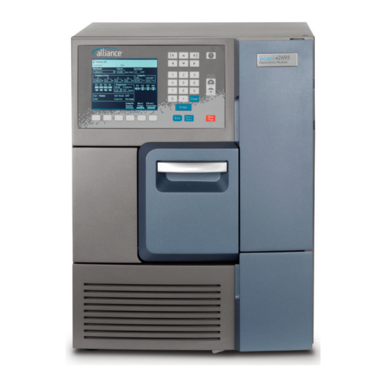
Waters Alliance e2695 Manuals
Manuals and User Guides for Waters Alliance e2695. We have
2
Waters Alliance e2695 manuals available for free PDF download: Operator's Manual
Waters Alliance e2695 Operator's Manual (306 pages)
Separation module
Brand:
Waters
| Category:
Control Unit
| Size: 3.04 MB
Table of Contents
General Information
3
Trademarks
3
Customer Comments
3
Contacting Waters
4
Safety Considerations
4
Considerations Specific to the Waters Alliance E2695 Separations Module
5
Canada Spectrum Management Emissions Notice
6
Electrical Power Safety Notice
6
Safety Hazard Symbol Notice
6
Equipment Misuse Notice
7
Safety Advisories
7
Operating this Instrument
7
Applicable Symbols
8
Audience and Purpose
8
Intended Use of the Waters Alliance E2695 Separations Module
9
Calibrating
9
Quality Control
9
EC Authorized Representative
10
Table of Contents
11
1 Getting Started with the Alliance E2695 Separations Module
21
Separations Module Overview
21
HPLC System Configurations
22
Solvent Bottle Tray Kits
23
Control of Chromatographic Functions
25
Spill Protection
26
Record-Keeping Functions
26
Power Supply
27
Solvent Management System Overview
27
Solvent Blending
28
Prime/Vent Valve
28
Plunger Seal-Wash System
28
Loss of Prime Protection
29
Preferred Plunger Stroke Volume
29
In-Line Vacuum Degasser
29
Sample Management System Overview
31
Flow Path
31
Normal Flow
32
Injection
32
Carousel Configuration
32
Vial Presence
33
Syringe Assembly
33
Operating Configurations
34
System Controller Mode
35
No Interaction Mode
37
Remote Control Mode
37
Options and Accessories
39
Column Heater
40
Column Heater/Cooler
40
Sample Heater/Cooler
40
Syringes
40
Sample Loops
40
Column Selection Valve
41
2 Install the E2695 Separations Module
45
Installation Overview
45
Site Requirements
46
Firmware and Software Requirements
47
Unpack
48
Connect to the Electrical Power Supply
48
Connect Tubing and Attachments
50
Install B-Series Detector Base and Drip Tray
50
Install a and C Series Drip Tray and Support Bracket
53
Install Solvent Supply Tubing
58
Install the Degasser Vent Tubing
59
Make Waste Line Connections
60
Install Needle-Wash and Plunger Seal-Wash Reservoirs
61
Connect the Column
62
Connect the Column Selection Valve
64
Connect the Detector
68
Signal Connections
69
I/O Signal Connections
71
Digital Signal Connections
75
Ethernet Connections
77
Add Hardware Options
78
Install an Optional Sample Loop
78
Install the Column Heater and Column Heater/Cooler
81
Install a Syringe
81
3 Prepare the E2695 Separations Module for Operation
83
Power-On the Separations Module
83
Startup Diagnostic Tests
83
The Main Screen
84
Operating Overview
84
Screen Display Overview
85
Use the Keypad
86
Enter Values in Parameter Fields
88
Configure the Separations Module
91
Set Configuration Parameters
91
Configure the Operating Mode
98
Prepare the Solvent Management System
103
Prepare Solvent Reservoirs
104
Degassing Solvents
105
Prime the Plunger Seal-Wash Pump
106
Prime the Solvent Management System
107
Prepare the Sample Management System for Operation
107
Purge the System
108
Prime the Needle-Wash Pump
109
Adjust the Seal Pack
110
Load Carousels
111
Procedures for Preparing the Separations Module for Operation
112
Prepare a New or Dry Separations Module for Operation
112
Prepare an Idle or Powered-Off Separations Module for Operation
113
Change from a Buffered Solvent to an Organic Solvent
114
Power-Off the Separations Module
114
Flush the Flow Path
115
Power-Off the Separations Module
115
4 Front Panel Control
117
Routine Startup
117
Reinitialize the System
118
Load Sample Vials
118
Remove the Carousel
118
Load Vials
118
Load the Carousel
119
Add New Sample Vials During a Run
119
Monitor Your HPLC System
119
Perform Direct Functions
123
Dry Prime the System
126
Run System Prep
128
Wet Prime the System
129
Purge the 2410 and 410 Reference Cell
132
Equilibrate the System
132
Condition the Column
133
Inject Samples
133
5 Automatic Runs
135
System Controller or no Interaction Mode
135
Controlled by Empower Software
136
Controlled by Masslynx Software
136
Perform Automatic Runs in a Standalone Mode
136
Run a Sample Set
137
View Sample Sets
139
Perform a Run from a Sample Template
140
Modify a Sample Set During a Run
141
Stop a Run
142
Perform Automatic Runs under Empower Software Control
142
Perform Automatic Runs under Masslynx Control
144
Perform an Automatic Run Using Masslynx Software
144
6 Create Methods, Sample Sets, and Sample Templates
145
Separation Methods
145
Sample Sets
146
Sample Templates
146
Create and Edit Separation Methods
146
Create a Separation Method
148
Edit a Separation Method
149
Copy and Edit a Separation Method
149
Lock and Unlock a Separation Method
150
Set Separation Method Parameters
150
Set Mobile Phase Screen Parameter Values
151
Set Sample Parameter Values
157
Set Autosampler Parameter Values
159
Set Column Parameter Values
161
Set I/O Parameter Values
162
Set Detector Parameters
166
Create and Edit a Sample Set
174
Link Rows in a Sample Set
179
Create a Sample Template
180
7 Maintenance
181
Maintenance Considerations
181
Safety and Handling
181
Proper Operating Procedures
182
Reinitialize the System
182
Spare Parts
182
Maintain the Solvent Management System
183
Overview
183
Remove the Head, Seal-Wash Assembly, and Plunger
185
Notes on Replacing the Plunger Seals
187
Replace the Seal-Wash Assembly Seals
190
Clean and Replace the Plunger
192
Replace an Inlet Check Valve Cartridge
194
Replace the In-Line Filter
196
Maintain the Sample Management System
197
Remove Side Panel of Separations Module
201
Replace the Lower Needle-Wash Frit
203
Replace the Injector Needle and Seal Pack
209
Clean the Sample Compartment
216
Safety and Handling
219
8 Diagnostic Testing and Troubleshooting
219
Proper Operation
219
Use the Error Log
220
Perform Main Diagnostic Tests
221
Exit the Diagnostics Screens
221
Prime the Plunger Seal-Wash Pump
223
Perform the Compression Check
224
Prime the Needle-Wash Pump
225
Adjust the Seals
226
Service Utilities Diagnostic Tests
228
Perform Other Diagnostic Tests and Functions
228
Perform the Motors and Valves Diagnostic Test
230
Sensors Diagnostic Function
233
Static Leak Test
234
Valve Leak Test
236
Head Removal and Replacement Function
237
Inputs and Outputs Test
237
Keypad Test
239
Display Test
239
Carousel Test
239
Sample Heater/Cooler Test
239
Defrost Sample Heater/Cooler Function
240
Column Heater or Column Heater/Cooler Test
241
Rebuild Injector Valves Function
242
Create a GPV Test Method
242
Verify the Firmware Checksum
243
Troubleshoot
243
General Troubleshooting Hints
243
When to Call Waters Technical Service
245
Troubleshoot Chromatography Problems
245
Troubleshooting Hardware Problems
252
A Safety Advisories
261
Warning Symbols
262
Specific Warnings
263
Caution Advisory
265
Warnings that Apply to All Waters Instruments and Devices
266
Warnings that Address the Replacing of Fuses
271
Electrical and Handling Symbols
273
Electrical Symbols
273
Handling Symbols
274
B Specifications
276
Physical Specifications
276
Environmental Specifications
276
Electrical Specifications
276
Solvent Management Specifications
279
Sample Management Specifications
281
Instrument Control and Communication Specifications
282
C Spare Parts
283
Solvent Management System Spare Parts
284
Sample Management System Spare Parts
285
Separations Module Spare Parts
286
Vials and Low Volume Inserts
286
D Solvent Considerations
291
Introduction
291
Clean Solvents
291
Solvent Quality
292
Solvent Reservoirs
292
Preparation Checklist
292
Water
293
Buffers
293
Tetrahydrofuran (THF)
293
GPC Solvents and Seal Choices
293
Solvent Compatibility
294
Solvents to Avoid
295
Solvents to Use
295
Solvent Miscibility
297
How to Use Miscibility Numbers (M-Numbers)
299
Buffered Solvents
300
Head Height
300
Solvent Viscosity
300
Mobile Phase Solvent Degassing
301
Gas Solubility
301
Vacuum Degassing
302
Wavelength Selection
302
UV Cutoffs for Common Solvents
303
Mixed Mobile Phases
304
Refractive Indices of Common Solvents
305
Advertisement
Waters Alliance e2695 Operator's Manual (234 pages)
Separations Module
Brand:
Waters
| Category:
Control Unit
| Size: 3.2 MB
Table of Contents
Trademarks
3
Customer Comments
4
Safety Considerations
4
Safety Hazard Symbol Notice
4
Considerations Specific to the Waters Alliance E2695 Separations Module
5
FCC Radiation Emissions Notice
6
Electrical Power Safety Notice
6
Equipment Misuse Notice
6
Safety Advisories
6
Operating this Instrument
7
Applicable Symbols
7
Audience and Purpose
8
Calibrating
8
Canada Spectrum Management Emissions Notice
8
EMC Considerations
8
Intended Use of the Waters Alliance E2695 Separations Module
8
ISM Classification: ISM Group 1 Class a
8
EC Authorized Representative
9
Table of Contents
11
1 Getting Started with the Alliance E2695 Separations Module
19
Separations Module Overview
19
HPLC System Configurations
20
Solvent Bottle Tray Kits
20
Control of Chromatographic Functions
22
Spill Protection
22
Record-Keeping Functions
23
Power Supply
23
Solvent Management System Overview
23
Solvent Blending
24
Prime/Vent Valve
24
Plunger Seal Wash System
24
Loss of Prime Protection
24
Preferred Plunger Stroke Volume
25
In-Line Vacuum Degasser
25
Sample Management System Overview
26
Flow Path
26
Normal Flow
27
Injection
27
Carousel Configuration
27
Vial Presence
28
Syringe Assembly
28
Operating Configurations
29
System Controller Mode
29
No Interaction Mode
30
Remote Control Mode
31
Options and Accessories
33
Column Heater
33
Column Heater/Cooler
33
Column Pre-Heater
33
Sample Heater/Cooler
33
Syringes
33
Sample Loops
34
Column Selection Valve
34
2 Install the E2695 Separations Module
37
Installation Overview
37
Site Requirements
38
Firmware and Software Requirements
39
Unpack the Instrument
39
External Connections
40
3 Prepare the E2695 Separations Module for Operation
41
Power-On the Separations Module
41
Start-Up Diagnostic Tests
41
The Main Screen
41
Operating Overview
42
Screen Display Overview
42
Use the Keypad
44
Enter Values in Parameter Fields
45
Configure the Separations Module
47
Set Configuration Parameters
47
Configure the Operating Mode
52
Prepare the Solvent Management System
56
Prepare Solvent Reservoirs
57
Degassing Solvents
57
Prime the Plunger Seal Wash Pump
58
Prime the Solvent Management System
58
Prepare the Sample Management System for Operation
59
Purge the System
59
Prime the Needle Wash Pump
60
Adjust the Seal Pack
61
Load Carousels
62
Prepare the Separations Module for Operation
62
Prepare a New or Dry Separations Module for Operation
63
Prepare an Idle or Powered-Off Separations Module for Operation
63
Change from a Buffered Solvent to an Organic Solvent
64
Power-Off the Separations Module
64
Flush the Flow Path
64
Power-Off the Separations Module
65
4 Front Panel Control
67
Routine Start-Up
67
Reinitialize the System
67
Load Sample Vials
67
Remove the Carousel
68
Load Vials
68
Load the Carousel
68
Add New Sample Vials During a Run
68
Monitor Your HPLC System
69
Perform Direct Functions
72
Dry Prime the System
74
Run System Prep
75
Wet Prime the System
76
Purge the 2410 and 410 Reference Cell
78
Equilibrate the System
78
Condition the Column
78
Inject Samples
79
5 Automatic Runs
81
System Controller or no Interaction Mode
81
Controlled by Empower Software
81
Controlled by Masslynx Software
82
Perform Automatic Runs in a Standalone Mode
82
Run a Sample Set
82
View Sample Sets
83
Perform a Run from a Sample Template
84
Modify a Sample Set During a Run
85
Stop a Run
86
Perform Automatic Runs under Empower Software Control
86
Considerations When Performing Runs Controlled by Empower Software
87
Perform Automatic Runs under Masslynx Control
87
Perform an Automatic Run Using Masslynx Software
88
6 Create Methods, Sample Sets, and Sample Templates
89
Separation Methods
89
Sample Sets
89
Sample Templates
90
Create and Edit Separation Methods
90
Create a Separation Method
91
Edit a Separation Method
92
Copy and Edit a Separation Method
93
Lock and Unlock a Separation Method
93
Set Separation Method Parameters
94
Set Mobile Phase Screen Parameter Values
94
Set Sample Parameter Values
100
Set Autosampler Parameter Values
101
Set Column Parameter Values
103
Set I/O Parameter Values
104
Set Detector Parameters
107
Create and Edit a Sample Set
113
Link Rows in a Sample Set
116
Create a Sample Template
117
7 Maintenance Procedures
119
Maintenance Considerations
119
Proper Operating Procedures
119
Reinitialize the System
119
Spare Parts
119
Troubleshooting with Connections INSIGHT
119
Safety and Handling
120
Maintain the Solvent Management System
121
Overview
121
Remove the Head, Seal Wash Assembly, and Plunger
123
Notes on Replacing the Plunger Seals
124
Replace the Seal Wash Assembly Seals
126
Clean and Replace the Plunger
128
Replace an Inlet Check Valve Cartridge
129
Replace the In-Line Filter
131
Maintain the Sample Management System
133
Remove Side Panel of Separations Module
135
Replace the Lower Needle Wash Frit (if so Equipped)
136
Replace the Injector Needle and Seal Pack
141
Clean the Sample Compartment
147
8 Diagnostic Testing and Troubleshooting
149
Proper Operation
149
Safety and Handling
149
Use the Error Log
150
Perform Main Diagnostic Tests
150
Exit the Diagnostics Screens
151
Prime the Plunger Seal Wash Pump
152
Perform the Compression Check
152
Prime the Needle Wash Pump
154
Adjust the Seals
154
Service Utilities Diagnostic Tests
156
Perform Other Diagnostic Tests and Functions
156
Perform the Motors and Valves Diagnostic Test
157
Sensors Diagnostic Function
159
Static Leak Test
161
Valve Leak Test
162
Head Removal and Replacement Function
163
Inputs and Outputs Test
164
Keypad Test
165
Display Test
165
Carousel Test
165
Sample Heater/Cooler Test
166
Defrost Sample Heater/Cooler Function
166
Column Heater or Column Heater/Cooler Test
167
Rebuild Injector Valves Function
168
Create a GPV Test Method
168
Verify the Firmware Checksum
168
Troubleshoot
169
General Troubleshooting Hints
169
When to Call Waters Technical Service
170
Troubleshoot Chromatography Problems
171
Troubleshooting Hardware Problems
175
A Safety Advisories
181
Warning Symbols
181
Specific Warnings
182
Notices
183
Bottles Prohibited Symbol
183
Required Protection
184
Warnings that Apply to All Waters Instruments and Devices
184
Warnings that Address the Replacing of Fuses
187
Electrical and Handling Symbols
189
Electrical Symbols
189
Handling Symbols
190
B External Connections
191
Connect to the Electrical Power Supply
191
Connect Tubing and Attachments
193
Install the B-Series Drip Tray
193
Install A- and C-Series Drip Tray and Support Bracket
195
Install Solvent Supply Tubing
199
Make Waste Line Connections
200
Install Needle Wash and Plunger Seal Wash Reservoirs
201
Connect the Column
202
Connect the Column Selection Valve
203
Connect the Detector
206
Signal Connections
207
I/O Signal Connections
208
Digital Signal Connections
211
Add Hardware Options
213
Install an Optional Sample Loop
214
Install the Column Heater and Column Heater/Cooler
216
Install a Syringe
216
C Specifications
217
Physical Specifications
217
Environmental Specifications
218
Electrical Specifications
218
Solvent Management Specifications
220
Sample Management Specifications
221
D Solvent Considerations
223
Introduction
223
Clean Solvents
223
Solvent Quality
223
Solvent Reservoirs
223
Preparation Checklist
224
Water
224
Buffers
224
Tetrahydrofuran (THF)
224
GPC Solvents and Seal Choices
224
Solvent Compatibility
225
Solvents to Avoid
225
Solvents to Use
226
Solvent Miscibility
228
How to Use Miscibility Numbers (M-Numbers)
229
Buffered Solvents
230
Head Height
230
Solvent Viscosity
230
Mobile Phase Solvent Degassing
230
Gas Solubility
231
Vacuum Degassing
231
Wavelength Selection
232
UV Cut-Offs for Common Solvents
232
Mixed Mobile Phases
233
Refractive Indices of Common Solvents
234
Advertisement
Related Products
Waters e-SAT/IN
Waters Elements Matt
Waters Extraction+
Waters 2545 Binary Gradient Module
Waters 2690
Waters 61164
Waters 61166
Waters 61168
Waters Bus SAT/IN
Waters Pump Control Module II
Waters Categories
Laboratory Equipment
Security Sensors
Control Unit
Measuring Instruments
Water Pump
More Waters Manuals
Login
Sign In
OR
Sign in with Facebook
Sign in with Google
Upload manual
Upload from disk
Upload from URL