Sign In
Upload
Manuals
Brands
Siemens Manuals
Medical Equipment
SONOLINE G50
Siemens SONOLINE G50 Manuals
Manuals and User Guides for Siemens SONOLINE G50. We have
2
Siemens SONOLINE G50 manuals available for free PDF download: Service Manual, Instructions For Use Manual
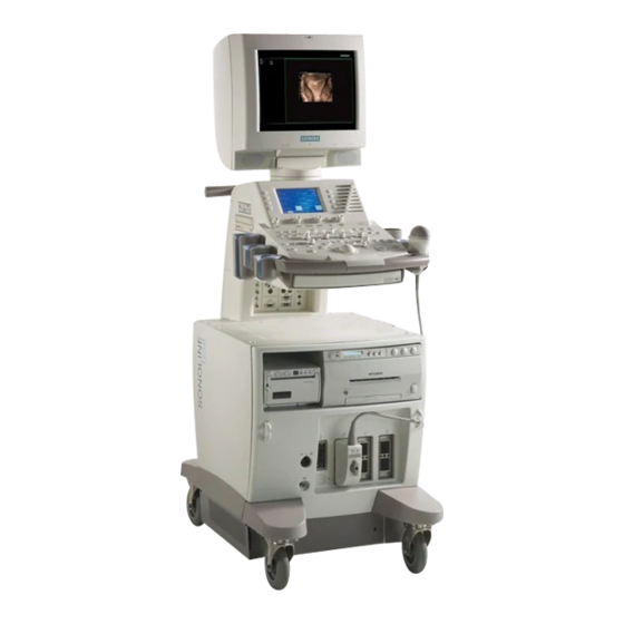
Siemens SONOLINE G50 Instructions For Use Manual (229 pages)
Ultrasound Imaging System
Brand:
Siemens
| Category:
Medical Equipment
| Size: 5.88 MB
Table of Contents
1 Introduction
8
About this Manual
3
Table of Contents
8
System Overview
10
Configurations
11
Language Formats
11
Transducers
11
Intended Use
12
Operating Modes
13
Image Screen Layout
14
Screen Saver
14
Documentation and Storage Devices
16
Measurements and Reports
17
User-Defined System Settings
18
Quicksets
18
2 Safety and Care
20
Operating Safety and Environment
22
System Symbols
22
Labels
25
Biohazard Considerations
27
Acoustic Output Mechanical and Thermal Indices
28
Mechanical and Thermal Indices
28
Transmit Power Control
29
Transmit Power Display
30
Imaging Functions that Change Acoustic Output
31
Transducer Surface Temperature Limits
32
Electrical Safety
33
Level of Protection against Electrical Shock Transducers
34
Defibrillators
34
Pacemakers
35
Electrical Safety MPT7-4
35
Possible Combinations with Other Equipment
35
Ultrasound System Care
36
Daily Checklist
36
Maintenance
37
Repair
37
Siemens Authorized Care
37
Cleaning and Disinfecting
39
Cleaning and Disinfecting the System
39
Cleaning an Air Filter
42
Documentation and Storage Devices Care
43
Transducers Care
44
Cleaning and Disinfecting Transducers
45
IPX8 Immersion Levels
47
Approved List of Disinfectants
49
Sterilizing Transducers VF13-5SP
50
Cleaning and Disinfecting Transducers MPT7-4
50
Storage
51
Repair
51
Protective Case
51
Transducer Accessories Care
52
Transducer Sheaths
52
Storage
52
Gel Pad
53
Storage
53
Needle Guide Bracket Kits
54
Storage and Transportation
54
Cleaning, Disinfecting, and Sterilizing Needle Guide Bracket Kits
54
Storage
56
3 System Controls
58
Control Panel
62
Control Panel Lighting
64
Control Panel Audio Signal
64
Trackball
64
Select
65
Caliper
66
Freeze
66
Patient Information Keys
67
New Patient
67
Patient Data
67
Exam
67
Selection and Entry Keys
67
Esc
67
Set
67
2D-Mode and M-Mode Imaging Controls
68
Split
68
Dual/Select
69
L/R
70
Rotate
70
Doppler and Color Flow Operation Keys
71
Triplex
71
Update
72
Angle
72
Power
73
Steer
73
Invert
73
Baseline
73
Gate
74
Prf
74
Image Parameter Controls
75
Dgc
75
Transducer
75
Multihertz
75
Depth/Zoom
76
Focus
76
Pictograms and Annotation
77
Text
77
Pictogram
77
Documentation Controls
78
Print/Store 1
78
Digital Store
78
Video I/O
79
Vcr
79
Review
79
Special Function Controls
80
Cine
80
Crescendo
80
Alphanumeric Keyboard
81
Special Characters
82
Function Keys
83
F1 - New Patient
83
F2 - Report
83
F3 - Patient Data
83
F4 - Preset Menu
83
F8 - Quickset
84
F9 - Home Set
84
F10 - Delete Line
84
F11 - Delete Text
84
F12 - Text
84
F13 - Biopsy
84
Other Alphanumeric Keys
85
Arrows
85
Alt
85
Backspace
85
Caps Lock
85
Ctrl
85
Del
85
End
85
Enter
85
Esc
86
Home
86
Pgdn
86
Pgup
86
Shift
86
Space Bar
86
Tab
86
Ins, Fn, Prtsc/Sysrq, Scroll Lock, and Pause Break
86
Footswitch
87
LCD Panel
88
LCD and LCD Keys
89
LCD Keys
89
Tabs
90
LCD Controls
91
Volume
91
LCD Control
91
Select-L
91
Select-R
91
Function Select
92
Transmit Power LCD Selections
93
2D-Mode LCD Selections
94
M-Mode LCD Selections
96
Doppler LCD Selections
97
Color Flow LCD Selections
98
Power Mode LCD Selections
100
CINE LCD Selections
101
Frame Recall (CINE) LCD Selections
102
ECG LCD Selections
103
LCD Selections for 2D-Mode Measurements and Calculations
104
LCD Selections for M-Mode Measurements and Calculations
106
LCD Selections for Doppler Measurements and Calculations
107
Disk Utility LCD Selections
108
VCR LCD Selections
109
Biopsy/Puncture LCD Selections
110
Siescape Panoramic Imaging Option LCD Selections
110
Selections Used in the Stress Echo Feature
111
Select Protocol to Load Dialog Box
111
Protocol Window
111
Stress Echo Screen
111
Toolbar Buttons Stress Echo
112
Select Mode Selections Stress Echo
114
Review Mode Selections Stress Echo
114
Wall Motion Scoring Mode Selections Stress Echo
115
LV Mode Selections Stress Echo
115
Maintenance Dialog Box Stress Echo
116
Protocol Editor Dialog Box Stress Echo
118
Selections in DIMAQ-IP
119
Lcd Dimaq-Ip
119
Study Screen DIMAQ-IP
119
Image Screen DIMAQ-IP
122
Report Screen DIMAQ-IP
124
DIMAQ Utility
125
Selections for 3D and 4D Imaging
126
3D LCD Selections During Acquisition
126
3D LCD Selections for Volume Viewing
127
3D Selections on the 3D Review Screen
128
View Tab Selections
128
Data Tab Selections
131
Advanced (Adv.) Tab Selections
131
Color Management Dialog Box Selections
132
Volume Toolbar Selections
135
Slice Toolbar Selections
137
DICOM Screen Selections
138
Study Screen
138
Image Screen
139
DICOM Screen
139
Printer Layout Pages
140
Print and Store Queues
141
4 System Setup
144
Initial Setup
146
Daily Checklist
146
System Review
147
Moving the System
150
Prior to the Move
151
During the Move
151
Shipping the System
152
After the Move
152
System Startup
153
Plugging in the System
153
Supplying Power to the System
155
Adjusting Controls on the Monitor
156
Testing the Monitor
158
Degaussing the Monitor
158
Adjusting Controls on the LCD
159
Audio Volume
159
Connecting and Disconnecting Transducers
160
Protective Transducer Holder
161
Array Transducers
163
Specialty Array Transducers
164
Mechanical Sector Transducers
165
Continuous Wave Transducers
166
Connecting System Accessories
167
Footswitch
167
ECG (EKG) Cables
167
External ECG
167
Input/Output Panel Connections
168
System Ergonomics
173
General System Settings
174
Modifying Hospital or Clinic Name
174
Setting System Date and Time
175
Software Installation
177
Installing and Reinstalling System Host Software
178
Software-Based Option Installation
180
5 Beginning an Examination
182
Entering Patient Data
184
Using the Patient Data Form
185
Calendar Tool
186
General and Exam-Specific Clinical Data
186
General Information All Exam Types
187
Specific Patient Data Information OB, Early OB, and GYN
188
Specific Patient Data Information C-Vas, P-Vas, Venous, and Surgical
189
Specific Patient Data Information Cardiac
189
Specific Patient Data Information Urology
189
Retrieving Existing Patient Data
190
Using the DICOM Modality Worklist Search Feature
192
Selecting Another Procedure
193
Fields Displayed on the Worklist Search Screen
194
Fields Displayed on the Choose Procedure Screen
194
Editing Patient Data
195
Changing the Exam Type
196
Accessing the Exam and Quickset List
196
Exam Type Abbreviations
197
Activating a Transducer
198
Selecting an Operating Mode
199
Examination Completion
200
Printing a Patient Report
200
Video Printer (On-Board)
200
Peripheral Printer (Off-Board)
200
Ending an Exam
201
6 Technical Description
202
Standard Features
204
Operator Control Panel
204
Multi-Lingual System Operating Software
204
Processing Power
204
High Resolution Color Monitor
205
User-Accessible Connections
206
Operating Modes
207
Single Modes
207
Imaging Functions
208
Pulsed Wave Doppler and Continuous Wave Doppler
208
Color Doppler
210
Power Doppler/Directional Power Doppler
211
Options
212
Measurements, Calculations, and Reports
213
General Functions
213
General 2D-Mode Measurements and Calculations
213
General Doppler Measurements and Calculations
214
Exam-Specific Measurements and Calculations
215
Abdominal
215
Surgical
215
Breast
215
Thyroid
215
Testicle
215
Gynecology
215
Urology
215
Obstetrics
216
Orthopedic
217
Cerebrovascular
217
Peripheral Vascular
217
Venous
217
Cranial
217
Cardiac
217
Measurement Accuracy
218
Linear Measurements on a Multi-Planar Image
218
Area Measurements on a Planar Quadrant
220
Image Display
222
Power Supply Requirements
224
Possible Combinations with Other Equipment
224
Leakage Currents
224
System Requirements
224
Audio, Video, and Data Transmission Connections Input and Output Signals
225
Video Standard
225
Environmental Requirements
226
Protective Measures
226
System Classifications
227
Standards Compliance
228
Design Standards
228
Advertisement
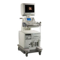
Siemens SONOLINE G50 Service Manual (235 pages)
Ultrasound Systems
Brand:
Siemens
| Category:
Medical Equipment
| Size: 6.24 MB
Table of Contents
Document Conventions
3
Hazard Alerts
3
Preface
3
Table of Contents
5
Chapter 1: Introduction and System Requirements
11
Introduction
12
The G50
12
G60 S Features Not Present on G50
12
The G60 S
13
Performance Specifications
14
System Specifications and Configurations
14
Supported Transducer Specifications
16
Mechanical and Electrical Specifications
18
Dimensions
18
Weight
18
Operating and Storage Environments
18
Temperature Specifications
19
Humidity Specifications
19
Altitude
19
Power Specifications
20
Voltage Supply Specifications
20
Power Supply Specifications
20
Fuse Ratings
20
Chapter 2: System Architecture
23
Control Panel
24
Monitor
24
Power Module
24
System Architecture
24
Host Module
25
E Module
26
E Module Component Comparison
26
Dimaq-Ip
29
Ecg
29
Component Locations
30
Host Module and DIMAQ-IP Circuits
30
G60 S (Left) and G50 (Right)
31
G60 S Front and Rear View
31
G50 Casters (Left) and the G60 S Casters (Right)
32
G60 S Control Panel and Keyboard
32
G50 Keyboard and Control Panel
33
Indicator Leds
33
Air Filter (Arrow Indicates Removal)
34
Interface Panel and OEM Bay
34
Line Filter (A05)
35
E Module of the G60 S Without Covers
36
G50 E Module with Covers
36
System Bus Description
37
Chapter 3: Power Distribution
39
Power Connections
40
Component Designations
40
G60 S Interconnections
41
Spare Parts Connections and Voltages
42
Control Panel
42
Chapter 4: Removing and Replacing Spare Parts
43
Introduction
44
Removing and Installing the Monitor
45
Tools Required
45
Removing the Monitor
45
Host Module Cover
46
Monitor and Post Covers
46
Attaching the Monitor Cables
47
Monitor and Post Attachment
48
Installing the Monitor
49
Bottom View of Monitor
49
Installing the Monitor Cover
50
Monitor Post Cover
51
Removing and Installing the Black and White Printer
52
Installing the Black and White Printer
53
Printer Removal from the OEM Bay
53
Verifying the Operation of the Black and White
54
P91W Cable Connections and Dip Switch
54
Installing the Color Printer and the VCR
56
OEM Bay and Top of Bay
56
Removing the Front Cover
57
Removing the Top Cover
58
CP900 Color Printer Connections
58
Installing the VCR
60
SVO-9500 VCR Connections
63
SVO-9500 and Interface Panel
63
Confirming the Operation of the Color Printer
64
Confirming the Operation of the VCR
64
Removing and Installing the DIMAQ-IP Module
66
DIMAQ-IP Module Installation
67
Installing the DIMAQ-IP Module
68
DIMAQ-IP Module Thumbscrews
68
Confirming the Operation of the DIMAQ-IP Module
68
Removing and Installing the Control Panel
70
Removing the Monitor Post Cover
71
Removing the Sub Control Panel (LCD)
71
Removing the Main Control Panel
72
Removing the Control Panel Fasteners
72
The Control Panel
73
A10 PC Board
73
Confirming the Operation of the Control Panel
74
Removing and Installing the Keyboard
75
Installing the Keyboard
76
Cables and Clamp under the Control Panel
76
Confirming the Operation of the Keyboard
77
Removing and Installing the MO Drive
78
Removing the MO Drive Bay
81
MO Drive and Bay Assembly
81
Installing the MO Drive
82
Confirming the Operation of the MO Drive
82
MO Drive Top View: DIP Switch Configuration
82
Removing and Installing the Host Module
83
Removing the Host Module Cable Clamp
83
OEM Interface Panel
84
Installing the Host Module
84
Routing the Host Module Cable
84
Confirming the Operation of the Host Module
85
Removing and Installing the E Module
86
Removing the EMI Shielding Bracket
87
Removing the E Module
87
Installing the E Module
88
Confirming the Operation of the E Module
88
Removing and Installing the Power Module
89
Installing the Power Module
90
Right Side (RH) and Top View of the Power Module
90
Confirming the Operation of the Power Module
91
Replacing the OEM Outlet Fuse
92
Replacing the Fuses
92
Xdst A07-1 (07473122)
92
Fuses
93
Removing and Installing the Third Array Port
94
Chapter 5: Installing Equipment Options
95
Installing the G50 DIMAQ-IP
96
Kit Contents
96
Disassembling the G50
97
Removing the Rear Cover
97
Removing the PPCL Shielding Plate
98
Installing the Wire Ties
99
Measuring the USB Cable
99
Installing the A70-2 PPCL PCB
100
Reinstalling the PPCL Shielding Plate
101
DIMAQ-IP Power-Cable Clamp
101
DIMAQ-IP Installation
102
Installing Cable Clamps
102
Testing the DIMAQ-IP
104
Installing DIMAQ-IP and Host Module Cables
104
Removing the DIMAQ-IP Module
104
Installing the G50 Third Array Port
105
Installing the Array Port
105
Removing the Probe Interface Panel
107
Installing the A36 A3RD-2 PCB
107
Removing the Array Port
108
Testing the Array Port
108
Installing the Probe Interface Panel
108
System Configuration – Hardware Screen (A36-2 Installed)
109
System Configuration – Hardware Screen (A36-2 Not Installed)
110
Chapter 6: Troubleshooting
111
Verifying the System Operation
112
Verifying the Operation of the System
112
Verifying the Operation of the Peripherals
112
Diagnostic Messages
113
Verifying the Operation of the DIMAQ-IP Module
113
Diagnostic Indicators
119
LED Legend
119
Boot Sequence
120
Troubleshooting the DIMAQ-IP
121
Diagnostic LED Status after Boot Completed
121
Review Switch Failure
121
Corrupted Images and Clips
122
Rebooting the System Software
122
Diagnostic Flow Charts
123
Hyperlinks
124
Troubleshooting Flow Chart (Starting Page)
124
B-Mode Imaging
127
Color Flow
128
Doppler
129
Oems and Peripherals
131
Chapter 7: Installing the Version 1.2 Software Update on the G60 S7-1
133
Backing up Service Data
134
Preparing for the Version 1.2 Software Update
134
Backing up Presets
135
Installing the Version 1.2 DIMAQ-IP Software Update
136
Installing the Version 1.2 System Software Update
138
Restoring the Service Data
138
Verifying the Operation of the Software
139
Chapter 8: Software
141
Installing or Updating the System Software
142
Installing or Updating the DIMAQ-IP Software
147
Determining the DIMAQ-IP Software Version
147
Installing the Product Feature Keys
150
Preset Screen
150
Stress Echo Maintenance Screen
152
Start Dialog Box
152
Uninstalling the Product Feature Keys
154
Feature Installation Screen
155
Service Software Operation
157
Starting up the Service Software
157
Service Software Start-Up Sequence
157
Authentication Screen
158
Service Screens and Menus
159
Exiting the Service Software
159
Main Menu Screen
159
Main Menu Screen Data
160
Main Menu Items
160
Navigation Controls
161
Site Information Screen
161
Data Fields
162
Control Buttons
163
Cancel Message Box
163
System Information Screen
164
Serial Number Message Box
164
System Configuration Screen for Hardware
165
System Configuration Screen for Software
165
System Configuration Screen for Peripherals
166
Transducer Screen
167
System Configuration for Peripheral
167
Transducer Information Screen
168
Diagnostics Screen
169
Log Screen
170
Key History Log Screen
170
Key History Log Formats
171
Clear Logged Data Message Box
171
Error Log Screen
172
Service History Screen
173
Viewing Service Records
174
Recording Service Activities
174
Editing Existing Service Records
175
Field Descriptions
175
Backup/Restore
176
Backup/Restore Screen
177
Service Data Backup Hierarchy
177
Disk Format Message Box
178
Name the Backup Message Box
178
Restoring Service Data
179
Service Data Restore Hierarchy
179
Imaging Test Pattern
179
Imaging Test Pattern Utilities
180
Black and White Test Pattern
180
Grayscale and Framing Pattern
181
Color Bar Pattern
181
Color Scale Pattern
182
Chapter 9: Planned Maintenance
183
Required Tools and Documents
184
Required Materials
184
Introduction
184
Preparations
185
Cleaning the System
185
Air Filter Removal
185
Cleaning and Inspecting Transducers
186
External and Internal Views of the Trackball
186
Safety Checks
187
System Test
188
Concluding the Maintenance
189
Appendix A: Installation Procedure
191
Unpacking the G50 and the G60 S
192
Installing the G50 or the G60 S
194
Documents Required
194
Installation
194
Appendix B: Installation Report
195
Appendix C: Spare Parts
197
G50 and G60 S Spare Parts
198
C-1 Spare Parts for the G50 and the G60 S
199
G50 and the G60 S Common Parts Photographs
201
Front View G50 Common Parts
202
Right Side View G50 Common Parts
202
Left Side View G50 Common Parts
203
07478824 A03 PWR Switching Reg, Assy, G50/G60 S
203
G50 Spare Parts Photographs
207
G50 Front View
207
C-16 G50 Rear View
208
C-17 G50 Left Side View
208
G50 Right Side View
209
7477966 G50 Caster
209
G50 E Module (Front View with Cover Installed)
210
7477933 CP Key Board, Assy, G50
210
G60 S Spare Parts Photographs
211
G60 S Front View
211
G60 S Rear View
211
G60 S Right Side View
212
07473171 Host, Module, G60 S
212
07482073 MS, E-Module, G60
213
07478717 CP Key Board, Assy, G60
213
NTSC and PAL Video Format
215
Appendix D: Video Formats
215
Service Data and File Extensions
217
Service Data Structure
217
Appendix E: Output Data File Structure
217
Output File Data Structure
218
Subsystem and Component Designations
223
Appendix F: Component Designations
223
Appendix G: Maintenance Report
227
Siemens Office
230
Measurement Devices
230
Comments
230
System Information
230
Open Issues
231
System Status
231
Customer Service Engineer Sign-Off
231
Planned Maintenance Checklist
232
Fastener Reference
233
H-1 Fastener Characteristics
233
Advertisement
Related Products
Siemens SONOLINE G60
Siemens Sonoline G20
Siemens VS 01 G 500
Siemens GU..D SERIES
Siemens OpenAir GLB164.1P
Siemens OpenAir GIB131.1U
Siemens OpenAir GIB164.1P
Siemens GEB 4 Series
Siemens GIGASET EUROSET 2015
Siemens Gigaset S45 trio
Siemens Categories
Industrial Equipment
Controller
Control Unit
Oven
Washer
More Siemens Manuals
Login
Sign In
OR
Sign in with Facebook
Sign in with Google
Upload manual
Upload from disk
Upload from URL