Page 1
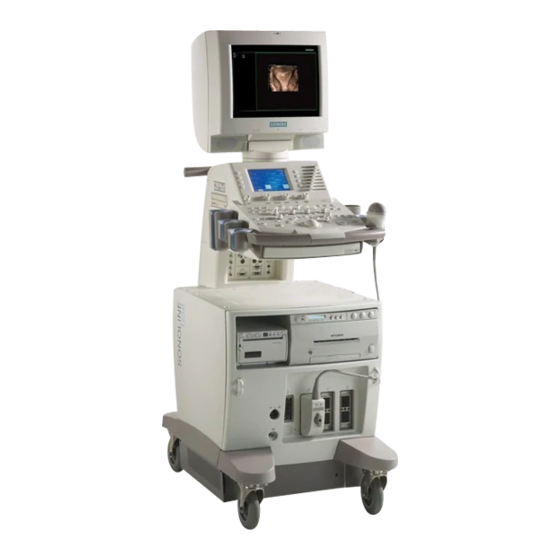
SONOLINE G50 and G60 S Ultrasound Systems Service Manual October 2002 7482255 Rev 01 Copyright 2002 Siemens Corporation. Wiedergabe sowie Vervielfältigung dieser Unterlage, Verwertung und Mitteilung ihres Inhalts nicht gestattet, soweit nicht ausdrücklich zugestanden. Zuwieder- Proprietary data, company confidential. All rights reserved.
Page 2
Assemblers and other persons who are not employed by or otherwise directly affiliated with or authorized by Siemens or one of its affiliates are directed to contact one of the local offices of Siemens or one of its affiliates before attempt- ing installation or service procedures.
Page 3
Additional information, not related to a specific sequence of steps in the proce- dure, is presented in the note format: Note: The UPTIME Service Center maintains a list of the current options for this equipment. Siemens 7482255 Rev 01 Page iii October 2002...
Page 4
G50 and G60 S - Service Manual Page iv 7482255 Rev 01 Siemens October 2002...
2.0 Removing and Installing the Monitor ............ 4-3 3.0 Removing and Installing the Black and White Printer ......4-10 4.0 Installing the Color Printer and the VCR ..........4-14 5.0 Removing and Installing the DIMAQ-IP Module ........4-24 Siemens 7482255 Rev 01 Page v October 2002...
5.0 Rebooting the System Software ............6-12 6.0 Diagnostic Flow Charts ................. 6-13 Chapter 7: Installing the Version 1.2 Software Update on the G60 S7-1 1.0 Installing the Version 1.2 Software Update ........... 7-2 Page vi 7482255 Rev 01 Siemens October 2002...
This chapter provides introductory information on the G50 and G60 S. The following topics are included in this chapter: 1.0 Introduction ...................1-2 2.0 Performance Specifications ............1-4 3.0 Mechanical and Electrical Specifications ........1-8 Siemens 7482255 Rev 01 Page 1 of 12 October 2002...
1.1 The G50 The SONOLINE G50 imaging system is a general purpose, high resolution digital ultrasound system which uses a Microsoft Windows® operating system. This ultrasound system supports linear and convex arrays using two ports.
Page 13
Three output devices are also available for the G60 S: Black and white printer: P91W (Standard) Color printer: CP900 (Option) VCR (SVO 9500 or SVO 3500) with mounting kit and cables (Option) Siemens 7482255 Rev 01 Page 3 of 12 October 2002...
PSP | QSP Synthetic Aperture Std (C6-2) Std (C5-2) Std (P4-2, C6-2) CINE B Mode 2B Mode M Mode 15 s 15 s D Mode 15 s 15 s CFM Mode Page 4 of 12 7482255 Rev 01 Siemens October 2002...
Page 15
1 track ball 1 track ball LCD (Sub Control Panel) Languages Std 5 language overlays Std 5 language overlays (English, German, (English, German, French, Spanish, Italian) French, Spanish, Ital- ian) Siemens 7482255 Rev 01 Page 5 of 12 October 2002...
Page 16
G60 S Specifications Physio Input ECG DC In Foot SW 2.2 Supported Transducer Specifications Table 1-3 lists the specifications for the transducers supported by the G50 or by the G60 S. Page 6 of 12 7482255 Rev 01 Siemens October 2002...
Page 17
Chapter 1 - Introduction and System Requirements Siemens 7482255 Rev 01 Page 7 of 12 October 2002...
G50 and the G60 S. Do not attempt to operate this system in extreme environments. Refer to the envi- ronmental specifications provided. Page 8 of 12 7482255 Rev 01 Siemens October 2002...
0% to 95% relative humidity, non-condensing. 3.2.3 Altitude The G50 and the G60 S design can operate at altitudes from 1060 hPa (-400 m or -1312 feet) to 700 hPa (3050 m or 10,000 feet). Siemens 7482255 Rev 01 Page 9 of 12 October 2002...
Page 20
100 Vac 6.3 A, 250V, slow blow (2 fuses) 07478774 115 Vac 6.3 A, 250V, slow blow (2 fuses) 07478774 230 Vac 4.0 A, 250V, slow blow (2 fuses) 07478782 Page 10 of 12 7482255 Rev 01 Siemens October 2002...
Page 21
Replace fuses only with the same current value and fuse type sup- plied by the factory and listed in Table 1-8. See "Spare Parts" (page C-1). See "Replacing the OEM Outlet Fuse" (page 4-50) for the fuse replacement procedure. Siemens 7482255 Rev 01 Page 11 of 12...
Page 22
Mechanical and Electrical Specifications Page 12 of 12 7482255 Rev 01 Siemens October 2002...
This chapter provides information on the architecture of the G50 and G60 S. The following topics are included in this chapter: 1.0 System Architecture ..............2-2 2.0 Component Locations ..............2-8 3.0 System Bus Description ..............2-15 Siemens 7482255 Rev 01 Page 1 of 16 October 2002...
The A03 switching regulator provides power to all of the included subsystems of the G50 and the G60 S. The switching regulator provides AC power directly to the monitor and connected OEMs via the A07-1 outlet distributor. Page 2 of 16 7482255 Rev 01 Siemens October 2002...
Page 25
DIMAQ option is installed. The PPCL uses the FS bus to provide a control link between the host module and the DIMAQ-IP. A70-1 SYFX: System Flash Annex This daughter board supplies an additional 32 MB of flash memory. Siemens 7482255 Rev 01 Page 3 of 16 October 2002...
Page 27
(Preamplifier) PCB. The output echo signal is sent to the A46 RXBF-2 (Receive Beamformer) PCB only. The A42 TXBF (Transmit beamformer) provides HV/MUX control, high voltage fault detection control and transducer transmit pulses for the A36 PSEL (Probe Select) PCB. Siemens 7482255 Rev 01 Page 5 of 16 October 2002...
Page 28
A48 BWPP (Black/White Parallel Processing) PCB, the A56-1 DPPR (Doppler) PCB and the A56 CFPR (Color Flow Processing) PCB. This PCB performs frame interpolation for all imaging modes and sends the image data to the Page 6 of 16 7482255 Rev 01 Siemens October 2002...
Page 29
The DIMAQ-IP software contains an application interface layer (API). Because this API operates between the applications (such as Stress-echo, etc.) and the system software, it is possible to upgrade or replace the DIMAQ-IP software or the system software individually. Siemens 7482255 Rev 01 Page 7 of 16 October 2002...
Figure 2-4 and Figure 2-5. Spare parts are listed in "Spare Parts" (page C-1). For a complete listing of all major components, see "Component Designations" (page F-1). For a listing of the system spare parts, see "Spare Parts" (page C-1). Page 8 of 16 7482255 Rev 01 Siemens October 2002...
Page 31
Figure 2-1 G60 S Front and Rear View Figure 2-2 provides a view of the right sides of the G60 S (left photo) and the G50 (right photo). Figure 2-2 G60 S (Left) and G50 (Right) Siemens 7482255 Rev 01 Page 9 of 16 October 2002...
Page 32
Figure 2-4 contains a detailed view of the control panel and keyboard of the G60 S. Sub Control Panel, Upper Main Control Panel, Lower Keyboard Figure 2-4 G60 S Control Panel and Keyboard Page 10 of 16 7482255 Rev 01 Siemens October 2002...
Page 33
Figure 2-6 shows the location of the indicator LEDs discussed in "Diagnostic Indicators" (page 6-9). The location of these LEDs is identical for the G50 and the G60 S. Figure 2-6 Indicator LEDs Siemens 7482255 Rev 01 Page 11 of 16 October 2002...
Page 34
Figure 2-7 Air Filter (Arrow Indicates Removal) Figure 2-8 indicates the location of the G60 S interface panel and the OEM bay. Interface Panel OEM Bay Figure 2-8 Interface Panel and OEM Bay Page 12 of 16 7482255 Rev 01 Siemens October 2002...
Page 35
Figure 2-9 shows the location of the line filter on the G60 S. Line Filter Figure 2-9 Line Filter (A05) Figure 2-10 indicates the G60 S power module and its subsystems. Figure 2-10 Power Module Siemens 7482255 Rev 01 Page 13 of 16 October 2002...
Page 36
E module of the G50; the optional third port is not installed. Figure 2-12 E Module of the G60 S Without Covers Figure 2-13 G50 E Module With Covers Page 14 of 16 7482255 Rev 01 Siemens October 2002...
Chapter 2 - System Architecture 3.0 System Bus Description Table 2-10, “Bus Summary,” on page 2-16 summarizes the communication buses located in the G50 and the G60 S. Siemens 7482255 Rev 01 Page 15 of 16 October 2002...
Page 38
System Bus Description Page 16 of 16 7482255 Rev 01 Siemens October 2002...
Chapter 3: Power Distribution This chapter provides information on the power distribution of the G50 and the G60 S. The following topics are included in this chapter: 1.0 Power Connections ...............3-2 Siemens 7482255 Rev 01 Page 1 of 4 October 2002...
Replace fuses only with the same current value and fuse type sup- plied by the factory and listed in Table 1-8. See "Spare Parts" (page C-1). See "Replacing the OEM Outlet Fuse" (page 4-50). Page 2 of 4 7482255 Rev 01 Siemens October 2002...
Page 41
Chapter 3 - Power Distribution DIMAQ-IP Figure 3-1 G60 S Interconnections Siemens 7482255 Rev 01 Page 3 of 4 October 2002...
#5_Pencil PSWONL A25J1 Inc. power supply SWRG A30-0 ECG Module SS-bus(E) Power Module 100V,115 V or 230 V 100V, 115V, or 230V A07-0 Figure 3-2 Spare Parts Connections and Voltages Page 4 of 4 7482255 Rev 01 Siemens October 2002...
10.0 Removing and Installing the E Module ........4-44 11.0 Removing and Installing the Power Module ........4-47 12.0 Replacing the OEM Outlet Fuse ..........4-50 13.0 Removing and Installing the Third Array Port ......4-52 Siemens 7482255 Rev 01 Page 1 of 52 October 2002...
Page 44
Fastener specifications are provided in "Fastener Reference" (page H-1). Note: See "Fastener Reference" (page H-1) for examples of the types of fasten- ers employed in the G50 and the G60 S. Page 2 of 52 7482255 Rev 01 Siemens October 2002...
3. Remove the two screws that secure the rear upper panel and remove the panel. 4. Remove two screws to remove the monitor post cover shown in Figure 4-4. 5. Remove two screws to remove the monitor cover shown in Figure 4-4. Siemens 7482255 Rev 01 Page 3 of 52 October 2002...
Page 46
G60 S contain hazardous voltages that can range from 90 Vac to 264 Vac. These volt- ages can cause serious injury or death. Verify that the safety ground is attached using the cor- rect hardware (see Figure 4-5) and that the screw is tight. Page 4 of 52 7482255 Rev 01 Siemens October 2002...
Page 47
9. Remove the monitor from the post. 10. Remove the mounting hardware from the original monitor; this hardware will be installed on the replacement monitor. Siemens 7482255 Rev 01 Page 5 of 52 October 2002...
Page 48
The monitor is heavy and could cause seri- ous injury. Always verify that the fasteners that attach the monitor are tightened securely so that the monitor will not loosen and fall. Page 6 of 52 7482255 Rev 01 Siemens October 2002...
Page 49
Insert the M4 X 12 screw through the lug attached to the safety ground cable, place the external tooth M4 lock washer on the screw, between the lug and the chassis, and install the screw in the chassis. Siemens 7482255 Rev 01 Page 7 of 52...
Page 50
13. Verify that the monitor turns easily without pinching any of the cables (Figure 4-5). 14. Install the monitor cover as shown in Figure 4-8. Figure 4-8 Installing the Monitor Cover Page 8 of 52 7482255 Rev 01 Siemens October 2002...
Page 51
Figure 4-9 Monitor Post Cover 16. Install the upper rear panel. 17. Tighten the two captive screws and install the caps. 18. Connect power to the monitor and verify that it operates properly. Siemens 7482255 Rev 01 Page 9 of 52 October 2002...
F located under the front of the printer, shown in Figure 4-10, and disconnect all of the cables from the rear of the P91W as you extract the P91W from the OEM bay. Page 10 of 52 7482255 Rev 01 Siemens October 2002...
Page 53
Off (downward). 4. Attach all of the cables shown in Figure 4-11 to the rear of the P91W as you insert it into the OEM bay. Siemens 7482255 Rev 01 Page 11 of 52...
Page 54
8. Turn on the power switch of the P91W. 9. Press F4 to display the Menu screen on the monitor. 10. Select Customize Keys from the menu, using the trackball. 11. Press SET. Page 12 of 52 7482255 Rev 01 Siemens October 2002...
Page 55
12. Select the B/W Printer for Set Up for PRINT/STORE 1 and press SET. 13. Select the SAVE button. 14. Press SET. 15. Press PRINT 1 and confirm that the displayed image prints correctly on the P91W printer. Siemens 7482255 Rev 01 Page 13 of 52 October 2002...
Use the following instructions to install the CP900 color printer in the G50 or the G60 S. Warning: Use threaded fasteners of the length cited here to avoid damaging or shorting under- lying equipment. Page 14 of 52 7482255 Rev 01 Siemens October 2002...
Page 57
The CK4x8 screws are M4x8 binding head screws with external lock washers. The screws designated as S3x8 are M3x8 flat head screws. See "Fastener Refe ence" (page H-1). Figure 4-13 Removing the Front Cover Siemens 7482255 Rev 01 Page 15 of 52 October 2002...
Page 58
Figure 4-14 Removing the Top Cover Figure 4-15 CP900 Color Printer Connections 3. Unfasten three pairs of magic fasteners joining the front cover to the G50 or the G60 S (Figure 4-13). Page 16 of 52 7482255 Rev 01 Siemens October 2002...
Page 59
X 8 binding head screws with external lock washers that were removed. 23. At the CP900, set the RGB IMPEDANCE switch to the 75 _/HIGH position and the SYNCHRONIZATION SIGNAL IMPEDANCE switch to the HIGH position. Siemens 7482255 Rev 01 Page 17 of 52 October 2002...
Page 60
See "Fastener Reference" (page H-1). 1. De-energize the system. 2. Place SVO-9500 VCR upside down on a flat surface. 3. Remove four rubber feet from the bottom of the VCR. Page 18 of 52 7482255 Rev 01 Siemens October 2002...
Page 61
Figure 4-16 Removing the Front Cover M4x10 screws Figure 4-17 Removing the Top Cover 5. Unfasten three pairs of magic fasteners joining the front cover and the G50 or the G60 S (Figure 4-16). Siemens 7482255 Rev 01 Page 19 of 52 October 2002...
Page 62
24. At the SVO-9500, position the S VIDEO IN IMPEDANCE switch to 75 _/ 25. Position the number 3 and the number 5 DIP switches in the On position. 26. At the P91W, position the number 1 DIP switch in the On position. Page 20 of 52 7482255 Rev 01 Siemens October 2002...
Page 63
29. Re-install the top cover on the G50 or the G60 S. 30. Re-install the front cover on the G50 or the G60 S. Figure 4-18 SVO-9500 VCR Connections Figure 4-19 SVO-9500 and Interface Panel Siemens 7482255 Rev 01 Page 21 of 52 October 2002...
Page 64
8. Turn on the SVO-9500 power switch and insert a S-VHS tape into the VCR. 9. Press F4 to display the Menu screen on the monitor. 10. Move the trackball upward and select Peripheral from the sub menu. 11. Press SET. Page 22 of 52 7482255 Rev 01 Siemens October 2002...
Page 65
17. After pressing VIDEO I/O, press REWIND on the LCD, then press PLAY to review the image and sound just recorded. 18. Confirm that no error message is displayed on the monitor. Siemens 7482255 Rev 01 Page 23 of 52...
Figure 4-20. 5. Disconnect all cables from the top surface of the host module (Figure 4- 20). Page 24 of 52 7482255 Rev 01 Siemens October 2002...
Page 67
11. Create sufficient clearance for dismounting the DIMAQ-IP module safely by routing the cables in front of it, and to the sides of the DIMAQ-IP module. 12. Move the DIMAQ-IP module to the left and dismount it from the system. Siemens 7482255 Rev 01 Page 25 of 52...
Page 68
4. Turn the Standby switch On. 5. Confirm that an image is displayed on the monitor. 6. Press REVIEW. 7. Confirm that the monitor shows the DIMAQ-IP module (Digital Lab) screen. Page 26 of 52 7482255 Rev 01 Siemens October 2002...
Page 69
Chapter 4 - Removing and Replacing Spare Parts 8. Move the trackball and confirm that the cursor moves accordingly. Siemens 7482255 Rev 01 Page 27 of 52 October 2002...
3. Pull the upper side of the rear cover carefully toward the rear of the system. 4. Remove two screws from the host module cover and remove the cover from the host module. Figure 4-22 Host Module Cover Page 28 of 52 7482255 Rev 01 Siemens October 2002...
Page 71
6. Loosen the two screws from the sub control panel shown in Figure 4-24. Rear Handle Figure 4-23 Removing the Monitor Post Cover (View from Under Rear Handle) Figure 4-24 Removing the Sub Control Panel (LCD) Siemens 7482255 Rev 01 Page 29 of 52 October 2002...
Page 72
4. Unlatch the hooks of the J1 connector on the A10 PC board (Figure 4-28), using the Phillips screwdriver, and disconnect the ribbon cable from J1. 5. Remove the control panel from the upper G50 or the G60 S. Page 30 of 52 7482255 Rev 01 Siemens October 2002...
Page 73
Install the control panel using the reverse sequence of the procedures provided for its removal. Caution: Use fasteners of the correct length to prevent damage to underlying equipment. See "Fastener Reference" (page H-1). Siemens 7482255 Rev 01 Page 31 of 52 October 2002...
Page 74
8. Use the controls on the control panel to produce an ultrasound image, and enter exam and patient data; verify that all controls located on the control panel operate properly. Page 32 of 52 7482255 Rev 01 Siemens October 2002...
Insert the M4 X 12 screw through the lug attached to the safety ground cable, place the external tooth M4 lock washer on the screw, between the lug and the chassis, and install the screw in the chassis. Siemens 7482255 Rev 01 Page 33 of 52...
Page 76
G60 S contain hazardous voltages that can range from 90 Vac to 264 Vac. These volt- ages can cause serious injury or death. Verify that the safety ground is attached using the cor- rect hardware and that the installation screw is tight. Page 34 of 52 7482255 Rev 01 Siemens October 2002...
Page 77
6. Confirm that each LCD display changes every time you press a soft key located next to the LCD cell. 7. Press the F4 key and confirm that Preset Main Menu is displayed on the monitor. Siemens 7482255 Rev 01 Page 35 of 52 October 2002...
5. Disconnect all cables from the top surface of the host module. 6. Disconnect the three cables from DIMAQ-IP module: When disconnecting the DIMAQ-IP power cable, unscrew its cable clamp as a single piece (Figure 4-37). Page 36 of 52 7482255 Rev 01 Siemens October 2002...
Page 79
12. Remove the two screws located under the rear handle and remove the monitor post cover from upper G50 or the G60 S as shown in Figure 4-32. 13. Loosen the two screws indicated in Figure 4-33. Siemens 7482255 Rev 01 Page 37 of 52...
Page 80
Caution: When the four screws are removed from the MO drive bay, the bay can fall free. Use caution, holding the MO drive bay securely, to prevent if from drop- ping and being damaged. Page 38 of 52 7482255 Rev 01 Siemens October 2002...
Page 81
23. Separate the MO drive from its shield case, by removing the one screw from the shield case that is indicated in Figure 4-35. Figure 4-35 MO Drive and Bay Assembly Siemens 7482255 Rev 01 Page 39 of 52 October 2002...
Page 82
6. Insert an MO disk into the MO drive: Verify that the MO disk is not write-pro- tected. 7. Press FREEZE. 8. Save the frozen image. 9. Load the saved image from the MO disk and verify that the image displays properly Page 40 of 52 7482255 Rev 01 Siemens October 2002...
6. Remove the cable clamp shown in Figure 4-37 from the left side of the host module cover by removing one screw. Figure 4-37 Removing the Host Module Cable Clamp Siemens 7482255 Rev 01 Page 41 of 52 October 2002...
Page 84
9.3 Installing the Host Module 1. Verify that the cables are securely positioned in both slits located at the sides of the opening shown in Figure 4-39. Figure 4-39 Routing the Host Module Cable Page 42 of 52 7482255 Rev 01 Siemens October 2002...
Page 85
7. Activate the Service software according to the instructions provided in "Ser- vice Software Operation" (page 8-17). 8. Access the "System Information Screen" (page 8-24). 9. Verify the system serial number and the system software version. Siemens 7482255 Rev 01 Page 43 of 52 October 2002...
8. Remove the fan enclosure by loosening the six screws that attach it to the system. 9. Remove the four screws indicated in Figure 4-40. Page 44 of 52 7482255 Rev 01 Siemens October 2002...
Page 87
E module: Pull the E module slowly toward you as indicated in Figure 4-41. Figure 4-41 Removing the E module Siemens 7482255 Rev 01 Page 45 of 52...
Page 88
2. Connect a transducer to the G50 or the G60 S. 3. Turn the power switch On. 4. Turn the Standby switch On. 5. Confirm that a B-mode image is displayed on the monitor. Page 46 of 52 7482255 Rev 01 Siemens October 2002...
7. Remove the power cover from the lower right of the G50 or the G60 S by removing two screws. 8. Remove three screws from the bottom frame of the system (Figure 4-43). Siemens 7482255 Rev 01 Page 47 of 52...
Page 90
Caution: Figure 4-43 shows only J1 and J2. There is a J3 connector not indi- cated in the photo. The J2 cable could be inadvertently installed in the J3 con- nector. Verify that the correct cable is installed at the J2 connector. Page 48 of 52 7482255 Rev 01 Siemens October 2002...
Page 91
2. Connect a transducer to the G50 or the G60 S. 3. Turn the power switch On. 4. Turn the Standby switch On. 5. Confirm that a B-mode image is displayed on the monitor. Siemens 7482255 Rev 01 Page 49 of 52 October 2002...
4. Pull the upper side of the rear cover toward you. 5. Locate the XDST (A07-1) PC board on the right side of the host module; see Figure 4-44. Figure 4-44 XDST A07-1 (07473122) Page 50 of 52 7482255 Rev 01 Siemens October 2002...
Page 93
9. After verifying that the system is operable, power down the system. 10. Replace the fuse cover. 11. Replace the host module cover and the rear cover. 12. Energize the system and verify its operation. Siemens 7482255 Rev 01 Page 51 of 52 October 2002...
The installation of the third array port option on the G50 system is provided in "Installing the G50 Third Array Port" (page 5-11). This information is appropriate for the removal and the reinstallation of the G50 port. Page 52 of 52 7482255 Rev 01 Siemens October 2002...
Note: See "Software" (page 8-1) for instructions covering the installation of soft- ware options. The following topics are presented in this chapter: 1.0 Installing the G50 DIMAQ-IP ............5-2 2.0 Installing the G50 Third Array Port ..........5-11 Siemens 7482255 Rev 01 Page 1 of 16 October 2002...
A70-2 PPCL 7479913 M3 X 6 screw M2.5 X 6 screw External lock washer Wire Ties Ethernet cable (straight) Ethernet cable (cross) USB cable VGA cable Serial cable Option label Page 2 of 16 7482255 Rev 01 Siemens October 2002...
Page 97
5. As shown in Figure 5-2, unscrew the cable clamp that secures the USB cable to the USB cable fixing bracket. 6. Remove the two screws from the USB cable fixing bracket and remove the bracket. Siemens 7482255 Rev 01 Page 3 of 16 October 2002...
Page 98
14. Install each wire tie through the IN hole and out of the OUT hole indicated, at the exact location shown. Page 4 of 16 7482255 Rev 01 Siemens October 2002...
Page 99
21. After fastening the wire ties, remove the excess portion of the wire ties with the side cutters. Figure 5-3 Installing the Wire Ties Figure 5-4 Measuring the USB Cable Siemens 7482255 Rev 01 Page 5 of 16 October 2002...
Page 100
Caution: Use care to avoid dropping loose hardware into the system during the disassembly and assembly of the G50. Loose hardware can short electronic components. Safeguard all hardware for reinstallation. Page 6 of 16 7482255 Rev 01 Siemens October 2002...
Page 101
Verify that no cable is pinched or abraded when the DIMAQ-IP is removed. 29. Move all cables to the sides of the system to allow access to the DIMAQ-IP installation site. Siemens 7482255 Rev 01 Page 7 of 16 October 2002...
Page 102
32. Reinstall the power-cable clamp shown in Figure 5-7 that was removed in step 28. See Figure 5-9. Figure 5-9 Installing Cable Clamps 33. Identify the cables that were detached from the host module in step 3. Page 8 of 16 7482255 Rev 01 Siemens October 2002...
Page 103
40. Verify that all cables are securely connected and protected from damage. 41. Reinstall the host module cover that was removed in step 3. Siemens 7482255 Rev 01 Page 9 of 16...
Page 104
1.5 Removing the DIMAQ-IP Module See "Removing and Installing the DIMAQ-IP Module" (page 4-24) for remove and replace procedures appropriate for both the G50 and the G60 S DIMAQ-IP module. Page 10 of 16 7482255 Rev 01 Siemens October 2002...
2. Move the G50 to a level location that provides 1 meter of clearance at the front and sides of the system. 3. Lock the 4 wheel locks. 4. De-energize the G50 and detach the power cord from the power outlet. Siemens 7482255 Rev 01 Page 11 of 16 October 2002...
Page 106
G50 to remove the probe interface panel. 13. From the rear of the probe interface panel just removed, unscrew the two screws to release the blank panel indicated in Figure 5-12. Page 12 of 16 7482255 Rev 01 Siemens October 2002...
Page 107
Figure 5-13 Installing the A36 A3RD-2 PCB 19. As indicated in Figure 5-14, reinstall the probe interface panel on the front of the G50, using the twelve M4 X 8 screws that were removed in step 11. Siemens 7482255 Rev 01 Page 13 of 16...
Page 108
8. Select the HW/SW button located on the Main Menu screen to display the System Configuration – Hardware screen as shown in Figure 5-15. 9. Scroll down the list, displayed on this screen, to the A36-2 assembly. Page 14 of 16 7482255 Rev 01 Siemens October 2002...
Page 109
Not Install ed If A36 A3RD-2 PCB has been A40- 3 RX32 Not Install ed successfully installed, a numeric value is shown here. Figure 5-15 System Configuration – Hardware Screen (A36-2 Installed) Siemens 7482255 Rev 01 Page 15 of 16 October 2002...
Page 110
Figure 5-16 System Configuration – Hardware Screen (A36-2 Not Installed) Note: To confirm the successful removal of the A36 A3RD-2 PCB, verify that “Not Installed” is displayed in the System Configuration – Hardware screen as shown in Figure 5-16. Page 16 of 16 7482255 Rev 01 Siemens October 2002...
11. Turn on the power switch of the CP900 color printer. 12. Press F4 to display the Menu screen on the monitor. 13. Move the trackball upward and select Customize Keys from the submenu. 14. Press SET. Page 2 of 22 7482255 Rev 01 Siemens October 2002...
Table 6-1, “Diagnostic Messages,” on page 6-4 lists the diagnostic messages and the error messages likely to be encountered when a failure occurs on a specific printed circuit board (PCB). Siemens 7482255 Rev 01 Page 3 of 22 October 2002...
Page 114
Diagnostic Messages Page 4 of 22 7482255 Rev 01 Siemens October 2002...
Page 115
Chapter 6 - Troubleshooting Siemens 7482255 Rev 01 Page 5 of 22 October 2002...
Page 116
Diagnostic Messages Page 6 of 22 7482255 Rev 01 Siemens October 2002...
Page 117
Chapter 6 - Troubleshooting Siemens 7482255 Rev 01 Page 7 of 22 October 2002...
Page 118
Diagnostic Messages Page 8 of 22 7482255 Rev 01 Siemens October 2002...
DIMAQ-IP module connected. Note: The LED designated with the V character represents the 5V supply. This LED is illuminated when 5V power is available. Siemens 7482255 Rev 01 Page 9 of 22...
Page 120
Display LCD and Startup Image Display Progress Bar Set RTC Copy System Software from Flash ROM Boot Windows CE and System Software Boot Complete Figure 6-2 Diagnostic LED Status During the Boot Sequence Page 10 of 22 7482255 Rev 01 Siemens October 2002...
Windows are running, but applications are not active. Loss of the trackball control indicates the loss of the internal Ethernet communication. Restart the DIMAQ-IP by rebooting Windows 2000 (Start → Restart). Siemens 7482255 Rev 01 Page 11 of 22...
3. Press and hold down the key bearing the small square on its key cap. 4. Press and hold down the Freeze key: Press and hold the New Patient + Square + Freeze keys to perform a soft boot of the system software. Page 12 of 22 7482255 Rev 01 Siemens October 2002...
Warning: The G50 and the G60 S contain hazardous voltages that can range from 90 Vac to 264 Vac. These voltages can cause serious injury or death. Only authorized service personnel are permitted to remove protective covers and access the energized components of this sys- tem. Siemens 7482255 Rev 01 Page 13 of 22 October 2002...
Page 125
Monitor LED Replace the monitor. green? Yellow indicates no synch. Displayed Monitor LED Replace host module. image Ok? green? Replace the monitor. Return Figure 6-5 Chart A: Monitor Siemens 7482255 Rev 01 Page 15 of 22 October 2002...
Page 126
LCD test Ok? Replace OPCT PC board. Replace sub panel. LED 3 on side Replace main panel. panel Ok? Return Replace host module. Figure 6-6 Chart B: Control Panel Page 16 of 22 7482255 Rev 01 Siemens October 2002...
Page 127
After test pattern diagnostic check, recycle the passed. system power Replace E module. CINE mode Replace E module. All B-mode problems Replace E module. resolved? Return Figure 6-7 Chart C: B-mode Imaging Siemens 7482255 Rev 01 Page 17 of 22 October 2002...
Page 128
Use LCD to select color map. Color map Replace host module. select Ok? CINE mode Replace E module All color flow Replace E module problems resolved. Return Figure 6-8 Chart D: Color Flow Page 18 of 22 7482255 Rev 01 Siemens October 2002...
Page 129
Replace E module. Doppler sound VCR playback Replace host module or OPCT sound Ok? (A10) PC board, Replace E module. CINE mode Replace E module. Return Figure 6-9 Chart E: Doppler Siemens 7482255 Rev 01 Page 19 of 22 October 2002...
Page 130
Replace ECG module. ECG display Replace E module. offset Ok? ECG trigger ECG trace has Replace ECG module. mode Ok? red marker? Replace E module. Return Figure 6-10 Chart F: ECG Page 20 of 22 7482255 Rev 01 Siemens October 2002...
Page 131
Replace host module. Printer, power USB printer cord, and switch Replace printer or power cord. Replace host module. Foot switch Replace host module. Return Figure 6-11 Chart G: OEMs and Peripherals Siemens 7482255 Rev 01 Page 21 of 22 October 2002...
Page 132
IPPC Pattern Check. Loop test 2 Replace host module. Replace cable. Replace IPPC module. All IPPC Replace IPPC module or host problems module. resolved. Return Figure 6-12 Chart H: DIMAQ-IP Page 22 of 22 7482255 Rev 01 Siemens October 2002...
(page 8-2) and "Installing or Updating the DIMAQ-IP Software" (page 8-7). Perform these procedures in the sequence listed: "Installing the Version 1.2 Software Update" (page 7-2) "Verifying the Operation of the Software" (page 7-7) Siemens 7482255 Rev 01 Page 1 of 8 October 2002...
Page 134
11. When the progress bar located on the Backup / Restore screen reaches 100% a Done message will be displayed. 12. Select the Home button and the Exit button to exit the service software. Page 2 of 8 7482255 Rev 01 Siemens October 2002...
Page 135
21. Select the Ok button; select the Ok button to close the message box and to continue. 22. Select the Utility tab and double-click MO and SONOLINE to view the con- tents of the MO diskette. Siemens 7482255 Rev 01 Page 3 of 8 October 2002...
Page 136
12. Close the upper-rear panel. 13. Press the F4 key and select the Service menu item. 14. Enter the service password and select the Ok button to display the Main Menu screen. Page 4 of 8 7482255 Rev 01 Siemens October 2002...
Page 137
35. Export the image file to the CD to verify its operation. 36. Verify that the exported image can be viewed by the system. 37. Delete the exported image from the HDD. Siemens 7482255 Rev 01 Page 5 of 8...
Page 138
3. Select the Backup/Restore button to display the Backup / Restore screen. 4. Select the Restore radio button located at the top of the screen. 5. Check the All Packages checkbox to restore all service data. Page 6 of 8 7482255 Rev 01 Siemens October 2002...
The number displayed on the System Information screen should be identical to the system Serial Number recorded on the label attached to the rear of the system. The installation of the version 1.2 software update is complete. Siemens 7482255 Rev 01 Page 7 of 8 October 2002...
Page 140
Verifying the Operation of the Software Page 8 of 8 7482255 Rev 01 Siemens October 2002...
2.0 Installing or Updating the DIMAQ-IP Software ......8-7 3.0 Installing the Product Feature Keys ..........8-10 4.0 Uninstalling the Product Feature Keys ..........8-14 5.0 Service Software Operation ............8-17 6.0 Service Screens and Menus ............8-19 Siemens 7482255 Rev 01 Page 1 of 42 October 2002...
Press the Review button to view the Study Screen. b. Select the MO Disk radio button. c. Select the Preset tab. d. Select the Store Quicksets button. e. Check the All Presets checkbox and select the Ok button. Page 2 of 42 7482255 Rev 01 Siemens October 2002...
Page 143
Eject and store the MO diskette. Caution: Update of the DIMAQ-IP software will destroy existing exam and patient information; back up exam and patient data before updating the DIMA-IP software. Siemens 7482255 Rev 01 Page 3 of 42 October 2002...
Page 144
7. Insert the MO diskette containing the version 1.2 software in the MO drive. 8. Press the F4 key to display the Preset screen shown in Figure 8-1. Scroll down to System/Language menu item. Figure 8-1 Preset Screen Page 4 of 42 7482255 Rev 01 Siemens October 2002...
Page 145
16. Press the MO eject button to remove the diskette. Note: If additional disks are required to complete the installation, follow the instructions displayed on the screen. Siemens 7482255 Rev 01 Page 5 of 42 October 2002...
Page 146
Serial No. is displayed: The number displayed on the System Information screen should be identical to the system Serial Number recorded on the label attached to the rear of the system. Page 6 of 42 7482255 Rev 01 Siemens October 2002...
Caution: Installation or upgrade of the DIMAQ-IP software will over-write all data on the HDD. Before beginning the installation of DIMAQ-IP software, back up all customer data that must be maintained, to a CD. Siemens 7482255 Rev 01 Page 7 of 42...
Page 148
17. After the system has powered down, wait 15 seconds and re-energize the system. Page 8 of 42 7482255 Rev 01 Siemens October 2002...
Page 149
1.2 system software installed. This opera- tion will fail and display the following message: “Please check the DIMAQ-IP software version; DIMAQ- IP will shut down soon.” Siemens 7482255 Rev 01 Page 9 of 42...
3. Press the F4 key to display the Preset screen shown in Figure 8-2. Figure 8-2 Preset Screen 4. Use the trackball to select the Installation from Key Disk menu item indi- cated in Figure 8-2. Page 10 of 42 7482255 Rev 01 Siemens October 2002...
Page 151
7. Insert the Stress Echo option key disk in the MO drive. 8. Use the trackball to select the Install button shown in Figure 8-3. 9. Press the SET key. Figure 8-3 Feature Installation Screen Siemens 7482255 Rev 01 Page 11 of 42 October 2002...
Page 152
14. On the Preset screen, select the Stress Echo menu item and press the SET key: The Maintenance screen shown in Figure 8-5 will be displayed. Figure 8-5 Stress Echo Maintenance Screen Page 12 of 42 7482255 Rev 01 Siemens October 2002...
Page 153
18. Install the Stress Echo option label provided, at the rear of the system, with the other option labels. 19. Store the Stress Echo Feature Key disk for future use. Siemens 7482255 Rev 01 Page 13 of 42 October 2002...
2. Press the F4 key to display the Preset screen shown in Figure 8-6. Figure 8-6 Preset Screen 3. Use the trackball to select the Installation from Key Disk menu item indi- cated in Figure 8-6. Page 14 of 42 7482255 Rev 01 Siemens October 2002...
Page 155
Preset screen (Figure 8-6) nor on the Installed Option list (Figure 8-7). 10. Eject the MO disk from the MO drive. Siemens 7482255 Rev 01 Page 15 of 42...
Page 156
11. Press the ESC key to exit from the Installation from Key Disk screen and return to the imaging screen. 12. Store the Stress Echo Feature Key disk for future use. Page 16 of 42 7482255 Rev 01 Siemens October 2002...
Figure 8-10. Start Open Preset Screen Select Ok Button Select Service Enter Password Select Ok Button Password Correct? Message: Password is Wrong Main Menu Displayed Figure 8-8 Service Software Start-up Sequence Siemens 7482255 Rev 01 Page 17 of 42 October 2002...
Page 158
Service Software Operation Service SIEMENS Authentication Service Software Site Name: XXXX Hospital System Serial Number: XXXXXX Product SW Version: X.X.XXX Please enter password Cancel Figure 8-9 Authentication Screen Page 18 of 42 7482255 Rev 01 Siemens October 2002...
Chapter 8 - Software Service SIEMENS Main Menu Service Software Site Name: XXXX Hospital System Serial Number: XXXXXX Product SW Version: X.X.XXX Site System HW/SW Transducer Diagnostics Service Backup / Imaging DIMAQ IP History Restore Test Pattern Maintenance Exit Figure 8-10 Main Menu Screen 5.2 Exiting the Service Software...
Page 160
Backup / Restore See “Backup/Restore” on page 8-36. Imaging Test Pattern See “Imaging Test Pattern” on page 8-39. DIMAQ-IP Maintenance See “Installing or Updating the DIMAQ-IP Software” on page 8-7. Page 20 of 42 7482255 Rev 01 Siemens October 2002...
Page 161
Main Menu screen (Figure 8-10). Use this screen to edit the value of the data fields located on this screen. Fields that have no assigned value are displayed blank. Siemens 7482255 Rev 01 Page 21 of 42...
Page 162
First Street 2 East A-54 HW / SW Street No 1234 Customer or Administrator Zip Code 95370 (408) 555-1212 Phone No Name Joseph Siemens South City City 01234567 Nebraska District Memo Diagnostics Country System is energized from CB 23-W34. Not approved for use Service History in Ward 67.
Page 163
Selecting the Cancel button, after display of this message, returns the screen to the state that existed before the Cancel button was pressed. Siemens 7482255 Rev 01 Page 23 of 42...
Page 164
G50 or the G60 S recorded on each printed circuit board varies among the circuit boards. Serial Number Please enter the Serial Number Cancel Figure 8-14 Serial Number Message Box Page 24 of 42 7482255 Rev 01 Siemens October 2002...
Page 165
Figure 8-15. Select the radio button labeled Software that is located on the right side of the System Configuration screen to display the System Configuration Software screen. Siemens 7482255 Rev 01 Page 25 of 42 October 2002...
Page 166
System Configuration screen to display the System Configuration Peripheral screen. Ten data rows are provided on this screen for recording the Equipment Name / Memo for the peripherals installed on the system. Page 26 of 42 7482255 Rev 01 Siemens October 2002...
Page 167
Service Home System Configuration - Peripheral Equipment Name / Memo Hardware Site Software Modem Siemens M12 28 / 2 / 2000 31 / 4 / 2001 System Peripheral HW / SW Diagnostics Service History Backup / Restore Cancel...
Page 168
Service Screens and Menus Service Home Transducer Site Probe Name Probe ID System 7L40+ 5C50+ HW / SW 3C40+ 6EV+ P4-2 C8-5 Diagnostics Service History Backup / Restore Figure 8-18 Transducer Information Screen Page 28 of 42 7482255 Rev 01 Siemens October 2002...
Page 169
See "Diagnostic Messages" (page 6-3) for information on the messages. To determine which spare part contains a failed component cited in the diagnostic message, see "Component Designations" (page F-1); "Spare Parts" (page C- 1) lists the spare parts. Siemens 7482255 Rev 01 Page 29 of 42 October 2002...
Page 170
Figure 8-20 Log Screen 6.9.1 Key History Log Screen Select the Key History Log button located on the Log screen (Figure 8-20) to display the Key History Log screen shown in Figure 8-22. Page 30 of 42 7482255 Rev 01 Siemens October 2002...
Page 171
OK button or cancel the deletion of the log data by selecting the Cancel button (Figure 8-21). Clear Do you want to delete the logged data? Cancel Figure 8-21 Clear Logged Data Message Box Siemens 7482255 Rev 01 Page 31 of 42 October 2002...
Page 172
The Clear key initiates the deletion of the Error Log data and displays a confirmation message box (see Figure 8-21); confirm or cancel the deletion of the error log data in this message box. Page 32 of 42 7482255 Rev 01 Siemens October 2002...
Page 173
Access the Service History screen shown in Figure 8-24 by selecting the Service History button located on the Main Menu screen (Figure 8-10). Use this screen to review previously recorded service activities and to record completed or on-going service activities. Siemens 7482255 Rev 01 Page 33 of 42 October 2002...
Page 174
Each service record allows the service engineer to enter key data in the fields labeled Key 1 through Key 5. These key field entries can be used to categorize the nature of the service activity for rapid review in the future. Page 34 of 42 7482255 Rev 01 Siemens October 2002...
Page 175
The History List contains the Date of Service recorded for each service activity. Selecting a date from this drop-down combo box, and then select- ing the View button, will display the data recorded for that service activity. Siemens 7482255 Rev 01 Page 35 of 42...
Page 176
MO diskette. Use the screen shown in Figure 8-25 to backup or restore the listed service data. Page 36 of 42 7482255 Rev 01 Siemens October 2002...
Page 177
Individual Packages Comment Category All Packages All service data packages Service All service data Site Information Site only System Information System only Hardware Information Hardware only Software Information Service data only Siemens 7482255 Rev 01 Page 37 of 42 October 2002...
Page 178
Service Backup Cancel Figure 8-27 Name the Backup Message Box Note: The system software assigns a name for the backup file, using the follow- ing date format: YYYYMMDDHHMMSS. Page 38 of 42 7482255 Rev 01 Siemens October 2002...
Page 179
Black and White Test Pattern: See Figure 8-29 Framing and Black and White Grayscale Pattern: See Figure 8-30 Color Bar Pattern: See Figure 8-31 Siemens 7482255 Rev 01 Page 39 of 42 October 2002...
Page 180
B & W Gray Scale Pattern Diagnostics Color Bar Pattern Service History Color Scale Pattern Backup / Restore Figure 8-28 Imaging Test Pattern Utilities Figure 8-29 Black and White Test Pattern Page 40 of 42 7482255 Rev 01 Siemens October 2002...
Page 181
Chapter 8 - Software Figure 8-30 Grayscale and Framing Pattern Figure 8-31 Color Bar Pattern Siemens 7482255 Rev 01 Page 41 of 42 October 2002...
Page 182
Service Screens and Menus Figure 8-32 Color Scale Pattern Page 42 of 42 7482255 Rev 01 Siemens October 2002...
4.0 Preparations .................9-3 5.0 Cleaning the System ..............9-3 6.0 Cleaning Subsystems ..............9-3 7.0 Cleaning and Inspecting Transducers ..........9-4 8.0 Safety Checks ................9-5 9.0 System Test ..................9-6 10.0 Concluding the Maintenance ............9-7 Siemens 7482255 Rev 01 Page 1 of 8 October 2002...
Page 184
Safety Test Report (p/n 7482768) are used during the planned mainte- nance procedure. 3.0 Required Materials Transmission gel is required to perform the testing and maintenance specified in this chapter. Page 2 of 8 7482255 Rev 01 Siemens October 2002...
6.0 Cleaning Subsystems Clean the following subsystems: 1. On each side of the system, remove the air filter retainer (2 total) as indi- cated in Figure 9-1. Figure 9-1 Air Filter Removal Siemens 7482255 Rev 01 Page 3 of 8 October 2002...
Note: Consult the Operating Instructions [kit] for the G50 and the G60 S for addi- tional information on transducers: Instructions for Use, System Reference, and the Transducer Reference. Page 4 of 8 7482255 Rev 01 Siemens October 2002...
6. With the system turned off, verify that all components and subsystems are properly secured and that all cables are properly connected. 7. Verify that mandatory system modifications have been made. Siemens 7482255 Rev 01 Page 5 of 8 October 2002...
12. Check system preset data, and restore from the disk if necessary. 13. Check the protective ground wire again. For detailed information refer to ARTD-002.731.17.01.02 (or newer). Page 6 of 8 7482255 Rev 01 Siemens October 2002...
Give the customer the completed maintenance report, and return a copy to your regional service office, as appropriate to your region. Note: Always keep a copy of the completed maintenance report for your own records. Siemens 7482255 Rev 01 Page 7 of 8 October 2002...
Page 190
Concluding the Maintenance Page 8 of 8 7482255 Rev 01 Siemens October 2002...
This appendix provides instructions for the unpacking and installation of the G50 and the G60 S. This section includes the following topics: 1.0 Unpacking the G50 and the G60 S ..........A-2 2.0 Installing the G50 or the G60 S ............A-4 Siemens 7482255 Rev 01 Page 1 of 4 October 2002...
Page 192
• Power cord (1) • Array transducer holder (4) • Sector transducer holder (1) • Gel bottle holder (1) • System software MO diskette (1) Page 2 of 4 7482255 Rev 01 Siemens October 2002...
Page 193
Appendix A - Installation Procedure Siemens 7482255 Rev 01 Page 3 of 4 October 2002...
7. Perform the system operational test according to "System Test" (page 9-6). 8. After successful completion of the system test, submit an installation report according to the instructions provided in "Installation Report" (page B-1). Page 4 of 4 7482255 Rev 01 Siemens October 2002...
Appendix B - Installation Report Appendix B: Installation Report Consult the Siemens Speed Info 001/2001/US for information on completing the Ultrasound System Installation Report (7295749) shown in Figure B-1. Access Speed Infos on the intranet at: http://www-td.med.siemens.de:88/. From this intranet page, select the following menu items to view SI 001/2001/ Product Information →...
Page 196
Figure B-1 Installation Report Form Page 2 of 2 7482255 Rev 01 Siemens October 2002...
Note: The photographs included in section 4, G60 S Spare Parts Photographs, show spare parts for the G60 S. In most cases, there are only minor differences in the appearance of the comparable spare part for the G50 system. Siemens 7482255 Rev 01 Page 1 of 18...
7472744 See Table 1-3 for transducers DIMAQ-IP Module, Exchange G50/G60 S 7478683 Figure C-11; IPPC E module, LC, G50 7477958 Figure C-15 E module, MS, G60 S 7482073 Figure C-26 Page 2 of 18 7482255 Rev 01 Siemens October 2002...
Page 199
Figure C-4 OEM Lower bay, Rear Cover, G50/G60 S 7478857 Overlay English, G50/G60 S 7479038 Figure C-3 Overlay German, G50/G60 S 7479046 Figure C-3 Overlay French, G50/G60 S 7479053 Figure C-3 Siemens 7482255 Rev 01 Page 3 of 18 October 2002...
Page 200
Sub Control Panel, Upper, Assy, G50/G60 S 7478709 Figure C-4, Figure C-5 Trackball, G50/G60 S 7478725 Figure C-3 VCR Sony-9500MD 4515404- L0800 VCR Sony-9500MDP 4515396 VF13-5 Exchange Transducer 5727243 See Table 1-3 for transducers Page 4 of 18 7482255 Rev 01 Siemens October 2002...
G50 and the G60 S. The G50 is shown in these photographs. Monitor 7475101 Probe Holder Long 7292084 Left Caster Bumper Cover 7479921(2 each) Right Caster Bumper Cover 7479939 (2 each) Figure C-2 Rear View G50 Common Parts Siemens 7482255 Rev 01 Page 5 of 18 October 2002...
Page 202
OEM Bay Top Shelf 7478840 Right Side Panel 7478873 Cable Hanger Front 7479020 Right Bumper Cover 7478600 Right Bottom Cover 7473148 Air Filter 7478923 Figure C-4 Right Side View G50 Common Parts Page 6 of 18 7482255 Rev 01 Siemens October 2002...
Page 203
Left Bumper Cover 7477354 Left Bottom Cover 7473130 Figure C-5 Left Side View G50 Common Parts Figure C-6 shows the switching power regulator. Figure C-6 07478824 A03 PWR Switching Reg, Assy, G50/G60 S Siemens 7482255 Rev 01 Page 7 of 18 October 2002...
Page 204
Figure C-8 shows the A07-1 XDST module containing the power fuses. Fuse Fuse Figure C-8 07473122 A07-1 XDST PCB, G50/G60 S (Fuses) Figure C-9 shows the control panel controller. Figure C-9 07482057 A10, CP Controller, G50/G60 S Page 8 of 18 7482255 Rev 01 Siemens October 2002...
Page 205
DIMAQ-IP image processor module. Figure C-11 07478683 Exchange, DIMAQ-IP, Module, G50/G60 S Figure C-12 shows the lower assembly of the main control panel. Figure C-12 07478691 Main CP, Lower, Assy, G50/G60 S Siemens 7482255 Rev 01 Page 9 of 18 October 2002...
Page 206
Figure C-13 shows the 15 inch color monitor. Figure C-13 07475101 OEM, Monitor Color SVGA, 15 inch, G50/G60 S Figure C-14 shows the sub control panel. Figure C-14 07478709 Sub CP, Upper, Assy, G50/G60 S Page 10 of 18 7482255 Rev 01 Siemens October 2002...
G50 system. Keyboard G50 7477933 LC, E Module G50 7477958 2 Ports Standard; Third Port Option Shown See Figure C-20 for standard configuration Caster G50 7477966 Figure C-15 G50 Front View Siemens 7482255 Rev 01 Page 11 of 18 October 2002...
Page 208
Cable Hanger Side G50 7478022 Rear Panel Upper G50 7477990 Rear Panel Lower G50 7478006 Figure C-16 G50 Rear View Left Side Panel G50 7477982 Figure C-17 G50 Left Side View Page 12 of 18 7482255 Rev 01 Siemens October 2002...
G60 S. In most cases, there are only minor differences in the appearance of the comparable spare part for the G50 system. Figure C-19 shows a caster for the G50. Figure C-19 7477966 G50 Caster Siemens 7482255 Rev 01 Page 13 of 18 October 2002...
Page 210
G50 E Module (Front View with Cover Installed) Figure C-21 shows the G50 keyboard. 7477933 See Figure C-27 for the G60 S keyboard. Figure C-21 7477933 CP Key Board, Assy, G50 Page 14 of 18 7482255 Rev 01 Siemens October 2002...
Page 211
Monitor Post Cover G60 S 7478915 Rear Panel Upper G60 S 7478899 Left Side Panel G60 S 7478865 Rear Panel Lower G60 S 7478907 Figure C-23 G60 S Rear View Siemens 7482255 Rev 01 Page 15 of 18 October 2002...
Page 212
G50 system. Figure C-25 shown the host module for the G60 S. Figure C-25 07473171 Host, Module, G60 S Page 16 of 18 7482255 Rev 01 Siemens October 2002...
Page 213
Figure C-26 shows the E module for the G60 S. Figure C-26 07482073 MS, E-Module, G60 Figure C-27 shows the G60 S keyboard. See Figure C-21 for the G50 keyboard. Figure C-27 07478717 CP Key Board, Assy, G60 Siemens 7482255 Rev 01 Page 17 of 18 October 2002...
Page 214
G60 S Spare Parts Photographs Page 18 of 18 7482255 Rev 01 Siemens October 2002...
700 mm 525 mm NTSC Format 480 mm 485 mm 864 mm 704 mm 700 mm 625 mm PAL Format 575 mm 570 mm Figure D-1 NTSC and PAL Video Format Siemens 7482255 Rev 01 Page 1 of 2 October 2002...
Page 216
Page 2 of 2 7482255 Rev 01 Siemens October 2002...
Page 217
<> (angle brackets) and the data which belongs to the tag. A tag is field name, and its data is the value for that field. Siemens 7482255 Rev 01 Page 1 of 6 October 2002...
Page 221
7 characters Maintenance-Log (Error 26 characters (fixed) Log) (Header) (240 Bytes) <Date, Time, Status, 35 characters Details> 25/08/2000, 14:24:59, Diag- 62 characters nostics, Voltage Power Error 100 characters X 100 data Siemens 7482255 Rev 01 Page 5 of 6 October 2002...
Page 222
Page 6 of 6 7482255 Rev 01 Siemens October 2002...
Page 223
XDST Extend Distributor RCLM Rush Current Limiter Module A08-1 FUSE Control Panel A10 OPCT Operator Controller A10-1 MANP Main Panel Track Ball A10-2 SUBP Sub Panel A10-3 SKBD Slide Keyboard Siemens 7482255 Rev 01 Page 1 of 4 October 2002...
Page 224
DVSC Digital Video & System Con- Module troller TBCC Time Base Correction Con- troller A70-1 SYFX System Flash Extender A70-2 PPCL Parallel PC Link RPVM Rear Panel & Video Control- Page 2 of 4 7482255 Rev 01 Siemens October 2002...
Page 225
ECG Floating Connector A30-2 ECGD ECG DC Connector DIMAQ-IP SPCL Serial PC Link Module A75-1 RadiSys A75-2 Hard Disk Drive A75-3 CD-R/W CD ROM (Read-Write) A75-4 Ethernet Card MODV MO Drive Siemens 7482255 Rev 01 Page 3 of 4 October 2002...
Page 226
Page 4 of 4 7482255 Rev 01 Siemens October 2002...
Print this maintenance report and enter the required data. Attach the report produced during the performance of the Electrical Safety Test: Field Electrical Safety Test Procedure (p/n 7482776). Supply a copy of these completed reports to the customer and to the regional office. Siemens 7482255 Rev 01 Page 1 of 6 October 2002...
Page 228
This page intentionally left blank. Page 2 of 6 7482255 Rev 01 Siemens October 2002...
Page 229
Contact Person: Phone: Customer Specific Number: Customer Number: Copyright 2002 Siemens Corporation. Wiedergabe sowie Vervielfältigung dieser Unterlage, Verwertung und Mitteilung ihres Inhalts nicht gestattet, soweit nicht ausdrücklich zugestanden. Zuwieder- Proprietary data, company confidential. All rights reserved. handlungen verpflichten zu Schadenersatz. Alle Rechte für den Fall der Patent- Confié...
Serial Number Date of Use Calibrated Until Date Ultrasound Phantom Electrical Safety Analyzer Comments System Information System: SONOLINE G50 – G60 S Serial Number: Software Version: Product Status: Maintenance Contract Number: Contract Type: Page 4 of 6 7482255 Rev 01...
Customer Service Eng. System Status The system has passed all Siemens recommended maintenance checks; it is okay to use. The system has problems that do not restrict its use. The system is okay to use. Siemens recommends scheduling service to repair these minor problems.
Transducer operational check okay. Freeze function okay. Peripherals operate properly. Preset data okay. Protective ground wire operational. Page 6 of 6 7482255 Rev 01 Siemens October 2002...
Page 233
Binding head, with external lock washer CR5x10 M5x10 Pan head, with spring lock and flat washers Figure H-1 S3x8 (M3x8 Flat Head Screw) Figure H-2 CK3x8 (M3 Binding Head with External Lock Washer) Siemens 7482255 Rev 01 Page 1 of 2 October 2002...
Page 234
Page 2 of 2 7482255 Rev 01 Siemens October 2002...