Table of Contents
Advertisement
Quick Links
Download this manual
See also:
Service Manual
Advertisement
Chapters
Table of Contents

Related Manuals for Siemens SONOLINE G50


Summary of Contents for Siemens SONOLINE G50
- Page 1 SONOLINE G50 Ultrasound Imaging System [1] Instructions for Use Siemens Medical Solutions USA, Inc. 10011770 REV 01...
- Page 2 Manuals distributed from the United States of America are printed in the United States of America. SONOLINE G50, SONOLINE G60 S, Axius, DTI, fourSight, 3-Scape, SieScape, MultiHertz, DIMAQ, microCase, ErgoDynamic, SynAps, QuickSet, SuppleFlex, Crescendo, and Evolve Package are trademarks of Siemens Medical Solutions USA, Inc.
-
Page 3: About This Manual
About This Manual The Instructions for Use consists of two volumes: [1] Instructions for Use The [1] Instructions for Use includes both a general overview and a technical description of the ultrasound imaging system. This manual contains detailed information on the safety and care of the ultrasound system and its transducers. - Page 4 Conventions Conventions used throughout this manual are listed below. Take a moment to familiarize yourself with these conventions. Cross-References [1] Instructions for Use This manual provides you information by topic. When additional information exists within this or other manuals, a reference graphic and the name of the Screen Saver Ch 1 Intended Use...
- Page 5 Warnings, Cautions, and Notes WARNING: Warnings are intended to alert you to the importance of following the correct operating procedures where risk of injury to the patient or system user exists. Caution: Cautions are intended to alert you to the importance of following correct operating procedures to prevent the risk of damage to the system.
- Page 6 Selection of On-Screen Objects The SET key on the control panel functions as a point-and-select device (similar to a computer mouse) when used with the trackball. To select an on-screen object such as a button or a symbol, roll the trackball to position the pointer (cursor) on the object and then press the SET key on the control panel.
- Page 7 Technical description of the ultrasound system. Technical Description Note: Not all features and options described in this publication are available to all users. Please check with your Siemens representative to determine the current availability of features and options. [ 1 ]...
-
Page 8: Table Of Contents
1 Introduction System Overview ....................3 Configurations ....................4 Language Formats.................. 4 Transducers.................... 4 Intended Use....................... 5 Operating Modes....................6 Image Screen Layout ..................7 Screen Saver ....................7 Documentation and Storage Devices............... 9 Measurements and Reports ................10 User-Defined System Settings................ 11 QuickSets .................... - Page 9 1 I n t r o d u c t i o n 1 - 2 [ 1 ] I N S T R U C T I O N S F O R U S E...
-
Page 10: System Overview
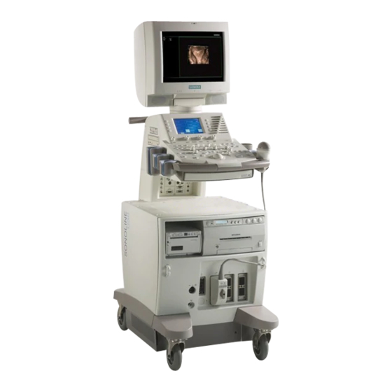
1 I n t r o d u c t i o n System Overview The SONOLINE G60 S™ system and the SONOLINE G50™ system are [1] Instructions for Use portable, all-digital, diagnostic ultrasound imaging systems for multi-specialty Technical and a variety of specialty and general applications. In addition to 2D-mode... -
Page 11: Configurations
Includes ECG and Steerable Continuous Wave Doppler hardware for adult cardiac applications. Includes the DIMAQ-IP integrated ultrasound workstation. The SONOLINE G50 system is available in 100V~, 115V~, and 230V~ mains voltage. Supports curved array, linear array, phased array (optional), and mechanical sector transducers (optional). -
Page 12: Intended Use
Caution: In the United States of America, federal law restricts this device to sale or use by, or on the order of, a physician. Listing of Transducers The SONOLINE G60 S ultrasound system and the SONOLINE G50 and Intended ultrasound system support the following applications: Application... -
Page 13: Operating Modes
Available with the SONOLINE G60 S system; requires the Cardiac Imaging option for the SONOLINE G50 system Available for the SONOLINE G60 S system only 1 - 6... -
Page 14: Image Screen Layout
1 I n t r o d u c t i o n Image Screen Layout The monitor on the ultrasound system displays clinical images together with important operating parameters and patient data. There is a variety of on-screen overlays and graphical objects to aid in image evaluation. Many fields or areas of data displayed on the screen are multi-functional. - Page 15 1 I n t r o d u c t i o n Sample Image Screen + - - Example of a typical image screen. 1 Time and Date, including an 8 Imaging Parameters. Displays abbreviation for the day of the week. parameters for 2D-mode, Color Flow or Power, M-mode, and Doppler.
-
Page 16: Documentation And Storage Devices
EN 60601-1-1 and IEC 60601-1-1. Siemens can only guarantee the performance and safety of the devices listed in the System Reference. If in doubt, consult Siemens service department or your local Siemens representative. -
Page 17: Measurements And Reports
Additional specialty measurements include Hip Dysplasia, Residual Volume, and Thyroid Volume. Available with the SONOLINE G60 S system; requires the Cardiac Imaging option for the SONOLINE G50 system 1 - 1 0 [ 1 ] I N S T R U C T I O N S... -
Page 18: User-Defined System Settings
1 I n t r o d u c t i o n User-Defined System Settings You can customize many features of the ultrasound system by using the presets system presets to designate default settings, or . The values are stored in non-volatile memory and will remain intact when the system is powered off. - Page 19 1 I n t r o d u c t i o n 1 - 1 2 [ 1 ] I N S T R U C T I O N S F O R U S E...
- Page 20 Possible Combinations with Other Equipment........16 Ultrasound System Care ................17 Daily Checklist ..................... 17 Maintenance....................18 Repair ....................18 Siemens Authorized Care..............18 Cleaning and Disinfecting ................20 Cleaning and Disinfecting the System..........20 Cleaning an Air Filter ................23 2 - 1...
- Page 21 2 S a f e t y a n d C a r e Documentation and Storage Devices Care ..........24 Transducers Care ................... 25 Cleaning and Disinfecting Transducers............26 IPX8 Immersion Levels................. 28 Approved List of Disinfectants ............. 30 Sterilizing Transducers VF13-5SP ............
-
Page 22: Operating Safety And Environment
2 S a f e t y a n d C a r e Operating Safety and Environment Do not operate the ultrasound imaging system until you fully understand the [1] Instructions for Use safety considerations and procedures presented in this manual. System Controls Ch 3 System Symbols... - Page 23 2 S a f e t y a n d C a r e Symbol Explanation Signal Input Signal Output Video Connection (monochrome video signals) Video Connection (RGB color video signals) Start (of action for equipment) Digital Interface, RS-232-C connection USB Connection Ethernet 10/100BaseT Connection Status Indicator for DC Power Good (Green) or Green...
- Page 24 2 S a f e t y a n d C a r e Symbol Explanation Keyboard Movement Indicator Keyboard Weight Restriction 11 lbs MAX 5 kg MAX ON only for MAINS control OFF only for MAINS control "ON" only for part of the equipment "OFF"...
-
Page 25: Labels
2 S a f e t y a n d C a r e Labels X-ray shielding notice System warning label Identification label Certification label 2 - 6 [ 1 ] I N S T R U C T I O N S F O R U S E... - Page 26 2 S a f e t y a n d C a r e Example of X-ray shielding notice: "X-ray emission complies with FDA (DHHS) radiation performance standards, 21 CFR subchapter J applicable at date of manufacture." Diagnostic Ultrasound System SONOLINE Xxxxxx Manufacture Date Nov.
-
Page 27: Biohazard Considerations
The ultrasound energy emitted by the transducer easily penetrates the fontanels of the infant. WARNING: Siemens makes every effort to manufacture safe and effective transducers. You must take all necessary precautions to eliminate the possibility of exposing patients, operators, or third parties to hazardous or infectious materials. -
Page 28: Acoustic Output Mechanical And Thermal Indices
2 S a f e t y a n d C a r e The ultrasound imaging system complies with the standards of the American Institute of Ultrasound in Medicine (AIUM), the National Electrical Manufacturer's Association (NEMA), the guidelines of the United States Food and Drug Administration (FDA), and the guidelines of the International Electrotechnical Commission (IEC) in terms of safety and acoustic output levels. -
Page 29: Transmit Power Control
2 S a f e t y a n d C a r e Indices display in the abbreviated form shown below: Mechanical Index TIB: Bone Thermal Index (fetal application) TIS: Soft Tissue Thermal Index TIC: Cranial Thermal Index Transmit Power Control Adjust the transmit power and the corresponding acoustic pressure delivered [1] Instructions for Use through the transducer to the patient by using the designated control on the... -
Page 30: Transmit Power Display
2 S a f e t y a n d C a r e Transmit Power Display The transmit power range is from –20 dB to 0 dB. Selecting 0 dB, or 100%, in System Reference combination with other system controls or functions generates the maximum System Presets Ch 3 acoustic intensity and mechanical index for each transducer, where:... -
Page 31: Imaging Functions That Change Acoustic Output
2 S a f e t y a n d C a r e Imaging Functions that Change Acoustic Output WARNING: Observe the real-time display of mechanical and thermal indices (MI/TI) at all times. In addition to the adjustment of the transmit power, adjustment of the following imaging functions and/or controls may affect the acoustic output: Automatic Time-out Temporal Color LCD selection... -
Page 32: Transducer Surface Temperature Limits
2 S a f e t y a n d C a r e Transducer Surface Temperature Limits The following table provides the maximum surface temperature of the [2] Instructions for Use transducers compatible with the system. MPT7-4 Temperature Maximum surface temperatures are in accordance with IEC 60601-2-37. Controls Ch C3 Maximum Temperature... -
Page 33: Electrical Safety
System Reference WARNING: To ensure proper grounding and leakage current levels, it is the policy of Siemens to have an authorized Siemens representative or Siemens- Peripheral approved third party perform all on-board connections of documentation and Devices Ch 4 storage devices to the ultrasound system. -
Page 34: Level Of Protection Against Electrical Shock Transducers
2 S a f e t y a n d C a r e WARNING: To maintain the safety and functionality of the ultrasound system, maintenance must be performed every 12 months. Electrical safety tests must also be performed at regular intervals as specified by local safety regulations, or as needed. -
Page 35: Pacemakers
EN 60601-1-1 and IEC 60601-1-1. Siemens can only guarantee the performance and safety of the devices listed in the System Reference. If in doubt, consult Siemens service department or your local Siemens representative. -
Page 36: Ultrasound System Care
If your system's power cord is frayed or split, or shows signs of wear, contact your Siemens service representative for power cord replacement. Verify that the trackball, DGC slide controls, and other controls on the control panel and LCD are clean and free from gel or other contaminants. -
Page 37: Maintenance
Perform inspections and maintenance at the prescribed intervals to avoid worn and hazardous parts due to wear. Contact the Siemens service department for information regarding the required maintenance. As manufacturers and installers of ultrasound equipment, Siemens cannot... - Page 38 EN 60601-1-1 and IEC 60601-1-1. Siemens can only guarantee the performance and safety of the devices listed in the System Reference. If in doubt, consult Siemens service department or your local Siemens representative.
-
Page 39: Cleaning And Disinfecting
2 S a f e t y a n d C a r e Cleaning and Disinfecting You must take all necessary precautions to eliminate the possibility of exposing patients, operators, or third parties to hazardous or infectious materials. Use universal precautions when cleaning and disinfecting. You should treat all portions of the imaging system that come in contact with human blood or other body fluids as if they were known to be infectious. - Page 40 2 S a f e t y a n d C a r e System Surfaces The following instructions describe cleaning the surface of the ultrasound system, including the trackball and transducer holder. To clean the surface of the ultrasound system: 1.
- Page 41 2 S a f e t y a n d C a r e To clean the trackball: Caution: Do not drop or place foreign objects inside the trackball assembly. This may affect the trackball's operation and damage the system. 1.
-
Page 42: Cleaning An Air Filter
2 S a f e t y a n d C a r e Cleaning an Air Filter The air filter on the ultrasound system must be cleaned regularly to maintain proper system cooling. Remove and check the air filter weekly, and clean as needed. -
Page 43: Documentation And Storage Devices Care
2 S a f e t y a n d C a r e Documentation and Storage Devices Care For information on the care of an optional documentation or storage device, please refer to the manufacturer's operating instructions that accompanied the device. -
Page 44: Transducers Care
2 S a f e t y a n d C a r e Transducers Care [2] Instructions for Use WARNING: Always place a sterile, non-pyrogenic transducer sheath on a transducer used in procedures requiring sterility. Transesophageal (MPT7-4) transducers Ch C3 WARNING: To minimize the risk of cross-contamination and infectious diseases, endocavity and intraoperative transducers must be cleaned and high-level disinfected after each use. -
Page 45: Cleaning And Disinfecting Transducers
Immersion Levels 2-28 WARNING: Disinfectants and cleaning methods listed are recommended by Siemens for compatibility with product materials, not for biological effectiveness. Refer to disinfectant label instructions for guidance on disinfection efficacy and appropriate clinical uses. [2] Instructions for Use Caution: Do not sterilize transducers using hot steam, cold gas, or Ethylene Oxide (ETO) methods. - Page 46 2 S a f e t y a n d C a r e To clean and disinfect a transducer: 1. Disconnect the transducer from the system. [2] Instructions for Use Transesophageal 2. Moisten a clean gauze pad with water and wipe the transducer to (MPT7-4) remove any gel or particles remaining on the transducer.
-
Page 47: Ipx8 Immersion Levels
"IPX8" symbol on the connector of the transducer. Example of transducer labels with IPX8 symbol. Endocavity transducers exceed minimum Ingress Protection level IPX7 of IEC 60601-2-18 to the depth of the immersion line shown in the illustration. SIEMENS Endocavity Linear Curved Phased Caution: Do not immerse the label located on the cable of the CW transducer. - Page 48 2 S a f e t y a n d C a r e Non-IPX8 Immersion Levels Caution: To avoid damage to the transducer, observe the immersion levels indicated for each transducer type. Transducers without the protection level IPX8 do not have the "IPX8" symbol on the connector of the transducer. If a transducer does not have the "IPX8"...
-
Page 49: Approved List Of Disinfectants
2 S a f e t y a n d C a r e Approved List of Disinfectants The following matrix provides a list of approved disinfectants for all transducers. Note: Cidex OPA and Gigasept FF may discolor transducer housings. There is no associated degradation of imaging performance or transducer reliability. -
Page 50: Sterilizing Transducers Vf13-5Sp
2 S a f e t y a n d C a r e Sterilizing Transducers VF13-5SP Caution: The transducers have been designed and tested to be able to withstand sterilization as recommended by the manufacturer of the sterilization system. Carefully follow the sterilization manufacturer's instructions. The STERRAD®... -
Page 51: Storage
Repair Do not attempt to repair or alter any part of the transducer. Contact your service representative at Siemens immediately if a transducer appears to be damaged or malfunctions in any way. Protective case Due to the mechanical sensitivity of transducers, Siemens recommends that... -
Page 52: Transducer Accessories Care
A sterile, non-pyrogenic transducer sheath must be in place during procedures requiring sterility. Caution: Siemens recommends that you follow all instructions provided by manufacturers of sterile goods (transducer sheaths) to ensure proper handling, storage, and cycling of all sterile goods. -
Page 53: Gel Pad
2 S a f e t y a n d C a r e Gel Pad Before use, examine the gel pad for any material flaws. Thinning, bulging, or brittleness of the material indicates damage. Any product showing flaws should not be used. Storage Do not store gel pads below 5°C nor above 57°C. -
Page 54: Needle Guide Bracket Kits
2 S a f e t y a n d C a r e Needle Guide Bracket Kits Needle guide bracket kits are available for biopsy and puncture procedures [2] Instructions for Use for specific transducers. Compatible Transducers Ch C1 Storage and Transportation Always clean and sterilize or high-level disinfect components used in a needle puncture or biopsy procedure after each use. - Page 55 2 S a f e t y a n d C a r e EC9-4 Stainless Steel Endocavity Needle Guide WARNING: Needle Guide Bracket kits are packaged non-sterile. Sterilize these products prior to their first use. The stainless steel endocavity needle guide is a reusable item. Refer to the in-box instructions for attachment and care procedures, including cleaning and sterilization.
-
Page 56: Storage
2 S a f e t y a n d C a r e Universal Needle Guide, Stainless WARNING: Needle Guide Bracket kits are packaged non-sterile. Sterilize these products prior to their first use. Refer to the sterilization procedures for the Universal Needle Guide in the following pages. - Page 57 2 S a f e t y a n d C a r e 2 - 3 8 [ 1 ] I N S T R U C T I O N S F O R U S E...
- Page 58 3 System Controls Control Panel ...................... 5 Control Panel Lighting ................... 7 Control Panel Audio Signal ................7 Trackball ......................7 Select ......................8 Caliper ......................9 Freeze......................9 Patient Information Keys ................10 New Patient ..................10 Patient Data..................10 Exam ....................
- Page 59 3 S y s t e m C o n t r o l s Image Parameter Controls................18 DGC...................... 18 Transducer ................... 18 MultiHertz .................... 18 Depth/Zoom ..................19 Focus....................19 Pictograms and Annotation ................. 20 Text ...................... 20 Pictogram .....................
- Page 60 3 S y s t e m C o n t r o l s Other Alphanumeric Keys................28 Arrows....................28 Alt......................28 Backspace .................... 28 Caps Lock..................... 28 Ctrl......................28 Del......................28 End ....................... 28 Enter..................... 28 ESC ...................... 29 Home ....................
- Page 61 3 S y s t e m C o n t r o l s LCD Selections for 2D-Mode Measurements and Calculations....47 LCD Selections for M-Mode Measurements and Calculations ....49 LCD Selections for Doppler Measurements and Calculations ..... 50 Disk Utility LCD Selections ................
-
Page 62: Control Panel
3 S y s t e m C o n t r o l s Control Panel The controls for all imaging modes, parameters, documentation, and LCD [1] Instructions for Use selections are designed to promote quick learning and recognition of the Keyboard 3-24 controls and functions. - Page 63 3 S y s t e m C o n t r o l s Example of the control panel on the ultrasound imaging system. 3 - 6 [ 1 ] I N S T R U C T I O N S F O R U S E...
-
Page 64: Control Panel Lighting
3 S y s t e m C o n t r o l s Control Panel Lighting When the imaging system is in use, all controls on the main control panel are back-lit. Use the system presets to select from among three levels of back-lit illumination. -
Page 65: Select
3 S y s t e m C o n t r o l s Select A dual-function control that activates one function when the control is pressed and another function when the control is rotated. When several functions are active, you can assign control of the trackball to any of the active functions by pressing the SELECT control. -
Page 66: Caliper
3 S y s t e m C o n t r o l s Caliper Activates the Measurement function. When you press the CALIPER key, the LCD displays measurement selections appropriate for the imaging mode and exam type. The system Caliper caliper also places the first marker in a... -
Page 67: Patient Information Keys
3 S y s t e m C o n t r o l s Patient Information Keys Use the patient information keys to input and edit patient data. New Patient Displays the new Patient Data entry form. The NEW PATIENT key on the control panel functions the same as the F1 key on the keyboard. -
Page 68: 2D-Mode And M-Mode Imaging Controls
3 S y s t e m C o n t r o l s 2D-Mode and M-Mode Imaging Controls Use the imaging controls to activate an operating mode, change the image orientation, or modify the sweep display. A dual-function control that activates one function when the control is pressed and another function when the control is rotated. -
Page 69: Dual/Select
3 S y s t e m C o n t r o l s Dual/Select Activates Dual-mode, which displays two separately acquired images, side-by-side. The DUAL/SELECT control consists of a set of two keys. The left key displays an image on the left side of the screen. The right key displays an image on the right side of the screen. -
Page 70: L/R
3 S y s t e m C o n t r o l s A dual-function control that activates one function when the control is pressed and another function when the control is rotated. Pressing the M control displays an M-mode cursor in a 2D image. You can then roll the trackball to place the cursor in the area of interest. -
Page 71: Doppler And Color Flow Operation Keys
3 S y s t e m C o n t r o l s Doppler and Color Flow Operation Keys Use these controls and keys to operate the Doppler and Color System Reference Flow functions. System Presets Ch 3 A dual-function control that activates one function when the control is pressed and another function when the control is rotated. -
Page 72: Update
3 S y s t e m C o n t r o l s Update Toggles a real-time display with a frozen display during mixed-mode imaging. For example, if a 2D-mode image is frozen while the Doppler spectrum is in real-time, pressing the UPDATE key causes the system to display the 2D-mode image in real-time while freezing the spectrum. -
Page 73: Power
3 S y s t e m C o n t r o l s Power Activates Power mode and displays the Power mode LCD selections. During Power mode, rotating the C control clockwise increases the Power Power gain; counterclockwise rotation decreases the Power gain. The range for gain settings is from 0 dB to 30 dB. -
Page 74: Gate
3 S y s t e m C o n t r o l s Gate Adjusts the size of the pulsed Doppler gate. Gate sizes are determined by transmit frequency. Gate Pushing the GATE control up increases gate size, and pushing the control down decreases the gate size. -
Page 75: Image Parameter Controls
3 S y s t e m C o n t r o l s Image Parameter Controls Use the image parameter controls to acquire and view an image. Display DGC Curve Increases or decreases the received gain for the depth of view. The receiver Display gain range is depth-dependent for the active transducer frequency. -
Page 76: Depth/Zoom
3 S y s t e m C o n t r o l s Depth/Zoom A dual-function control that activates one function when the control is rotated and another function when the control is pressed and then rotated. Rotating the DEPTH/ZOOM control changes the imaging depth. For software versions 1.2 and higher: Rotate the DEPTH/ZOOM control clockwise to decrease depth and counterclockwise to increase depth. -
Page 77: Pictograms And Annotation
3 S y s t e m C o n t r o l s Pictograms and Annotation [2] Instructions for Use Use the pictogram and annotation controls to display text and graphics depicting anatomical structures on-screen. Annotations Ch A1 Pictograms Ch A1 Text... -
Page 78: Documentation Controls
3 S y s t e m C o n t r o l s Documentation Controls Use the documentation controls to access recording devices for printing, storing, or retrieving images and imaging parameters. Customize Keys Print/Store 1 Primary print control. Sends the image or report on the screen to an installed documentation device. -
Page 79: Video I/O
3 S y s t e m C o n t r o l s Video I/O Displays a video signal that originates from an outside source, such as a VCR, on the system monitor. If a VCR is the outside source, pressing VIDEO I/O causes the system to display selections for controlling the VCR Video I/O on the LCD. -
Page 80: Special Function Controls
3 S y s t e m C o n t r o l s Special Function Controls Keys or controls marked with the symbol are reserved for future use. CINE Activates the CINE function and displays CINE LCD selections. Use the system presets to automatically activate the CINE function each CINE time you press the FREEZE key. -
Page 81: Alphanumeric Keyboard
3 S y s t e m C o n t r o l s Alphanumeric Keyboard Use the alphanumeric keyboard for entering patient data, selecting an exam type, annotating clinical images, and configuring the system presets. The retractable keyboard is located underneath the control panel. The keyboard is arranged like a standard computer keyboard. -
Page 82: Special Characters
3 S y s t e m C o n t r o l s Special Characters The system supports some language's special characters through the use of a combination of keys on the keyboard. The ALT key located on the left or right side of the keyboard accesses the special characters located on the upper right of a key. -
Page 83: Function Keys
3 S y s t e m C o n t r o l s Function Keys The F keys located in a row across the top of the alphanumeric keyboard are function keys called . These keys are used to access patient data and reports, select an exam type, configure presets, define a QuickSet, activate a biopsy (puncture) procedure, and activate the annotation function. -
Page 84: F8 - Quickset
3 S y s t e m C o n t r o l s F8 – QuickSet Accesses the screen for saving, deleting, and overwriting QuickSets (a configuration of imaging settings for a specific transducer and exam type). F9 – Home Set Sets the default location of the text cursor. -
Page 85: Other Alphanumeric Keys
3 S y s t e m C o n t r o l s Other Alphanumeric Keys Arrows Repositions the text cursor in the direction shown on the arrow key. Accesses special characters on the upper right of the keys located on the keyboard. -
Page 86: Esc
3 S y s t e m C o n t r o l s Performs same functions as the ESC key on the control panel. Home Places the text cursor in the Home position (as defined with the F9 key) Home when the Annotation function is active. -
Page 87: Footswitch
3 S y s t e m C o n t r o l s Footswitch Use the optional footswitch as an alternative to operating keys on the control panel. Pedal 1 is assigned to the Freeze/Unfreeze function; pressing this pedal is equivalent to using the FREEZE key on the control panel. Use Customize Keys the system presets to assign Pedal 2 to one of the following functions: Pedal 2 function... -
Page 88: Lcd Panel
3 S y s t e m C o n t r o l s LCD Panel The Liquid Crystal Display (LCD) panel contains the LCD, LCD keys, [1] Instructions for Use DGC slider controls, and controls used in conjunction with the LCD and DGC slider controls 3-18 other functions. -
Page 89: Lcd And Lcd Keys
3 S y s t e m C o n t r o l s LCD and LCD Keys The LCD lists options and functions for image optimization, transducer selection, measurements, image annotation, biopsy and puncture guidelines, CINE, image review, image storage, and tabs for the active mode(s) and functions. -
Page 90: Tabs
3 S y s t e m C o n t r o l s Changing a Setting of an LCD Selection If multiple settings for a highlighted selection are available, rotate the SELECT-L control or SELECT-R control to change a setting. For example, during 2D imaging, the LCD includes a selection for dynamic range (DR). -
Page 91: Lcd Controls
3 S y s t e m C o n t r o l s LCD Controls The LCD controls include an audio control, LCD brightness and contrast adjustments, and LCD selection tools. Volume Rotating the control clockwise increases the speaker volume; counterclockwise rotation decreases the volume. -
Page 92: Function Select
3 S y s t e m C o n t r o l s Page Accesses multiple LCD pages within a mode or function. Push the PAGE control to cycle through the available pages. The upper right corner of the LCD shows current page number/total number of pages available. -
Page 93: Transmit Power Lcd Selections
3 S y s t e m C o n t r o l s Transmit Power LCD Selections You can access the transmit power LCD selections by rotating the FUNCTION SELECT control on the LCD panel to highlight the Tx tab on the LCD. -
Page 94: 2D-Mode Lcd Selections
Reset Map Resets the current Gray Map curve back to the original factory position. Scan Angle (Available for the SONOLINE G50 system only) 220, 160, 110, 80 Adjusts the scan angle of the Endo-V II mechanical sector transducer. Modify Map... - Page 95 (Available with the SONOLINE G60 S system; requires the Cardiac On, Off Imaging option for the SONOLINE G50 system) Doubles the frame rate. Independent of the parallel processing in Color mode. This selection is available for phased array transducers.
-
Page 96: M-Mode Lcd Selections
3 S y s t e m C o n t r o l s M-Mode LCD Selections When M-mode is active, you can access the related LCD selections by rotating the FUNCTION SELECT control on the LCD panel to highlight the M tab on the LCD. -
Page 97: Doppler Lcd Selections
3 S y s t e m C o n t r o l s Doppler LCD Selections When Doppler is active, you can access the related LCD selections by rotating the FUNCTION SELECT control on the LCD panel to highlight the D tab on the LCD. -
Page 98: Color Flow Lcd Selections
Selects PSP (Parallel Signal Processing), QSP (Quad Signal Processing), or Off. The Color PSP is independent of the 2D-mode PSP. The PSP setting on the SONOLINE G50 system requires the use of a phased array transducer. The QSP setting is only available for phased array transducers. - Page 99 3 S y s t e m C o n t r o l s LCD Selection Description Settings Motion Cut Increases or decreases the threshold of the high pass 1, 2, 3, or 4 filter. Higher settings provide more filtering and reduction of motion artifacts.
-
Page 100: Power Mode Lcd Selections
PSP/QSP (Available with the SONOLINE G60 S system; requires the Off, PSP Cardiac Imaging option for the SONOLINE G50 system) Selects Parallel Signal Processing or Quad Signal Processing. The QSP setting is only available for phased array transducers. Available for the SONOLINE G60 S system only. -
Page 101: Cine Lcd Selections
3 S y s t e m C o n t r o l s LCD Selection Description Settings Motion Cut Increases or decreases the threshold of the high pass filter. 1, 2, 3, or 4 Higher settings provide more filtering and reduction of motion artifacts. -
Page 102: Frame Recall (Cine) Lcd Selections
3 S y s t e m C o n t r o l s Frame Recall (CINE) LCD Selections You can access the Frame Recall (CINE) LCD selections by rotating the FUNCTION SELECT control on the LCD panel to highlight the CINE tab on the LCD. -
Page 103: Ecg Lcd Selections
3 S y s t e m C o n t r o l s ECG LCD Selections When ECG is active, you can access the related LCD selections by rotating the FUNCTION SELECT control on the LCD panel to highlight the ECG tab on the LCD. -
Page 104: Lcd Selections For 2D-Mode Measurements And Calculations
3 S y s t e m C o n t r o l s LCD Selections for 2D-Mode Measurements and Calculations When the Measurement function is active, you can access these selections by rotating the FUNCTION SELECT control on the LCD panel to highlight the 2D tab on the LCD. - Page 105 3 S y s t e m C o n t r o l s LCD Selection Description 1Pl Ellipse Calculate volume by measuring an area with an ellipse and identifying the axis common to both planes. 1Pl LxD Calculate volume by measuring length and depth in one plane and assuming the same dimensions in the second plane.
-
Page 106: Lcd Selections For M-Mode Measurements And Calculations
3 S y s t e m C o n t r o l s LCD Selections for M-Mode Measurements and Calculations When the Measurement function is active, you can access these selections by rotating the FUNCTION SELECT control on the LCD panel to highlight the M tab on the LCD. -
Page 107: Lcd Selections For Doppler Measurements And Calculations
3 S y s t e m C o n t r o l s LCD Selections for Doppler Measurements and Calculations When the Measurement function is active, you can access these selections by rotating the FUNCTION SELECT control on the LCD panel to highlight the D tab on the LCD. -
Page 108: Disk Utility Lcd Selections
3 S y s t e m C o n t r o l s Disk Utility LCD Selections LCD Selection Description HD/CD-RW If DIMAQ-IP is installed on the system, displays DIMAQ-IP's Study screen, listing (displayed during image studies stored on either the system's hard disk or the inserted compact disk (CD). recall or when Utility or Preset tab is active) Disk Utility... -
Page 109: Vcr Lcd Selections
3 S y s t e m C o n t r o l s VCR LCD Selections LCD Selection Description Rewind Rewinds the tape without viewing the contents on the image screen. Fast Forward Advances the tape without viewing the contents on the image screen. Tape Search Reviews video playback in a forward or backward direction. -
Page 110: Biopsy/Puncture Lcd Selections
3 S y s t e m C o n t r o l s Biopsy/Puncture LCD Selections Use the system presets to enable the Biopsy function to automatically activate when an exam type is selected. Default Setting Biopsy LCD Selection Description Reset Angle Restores the original position of the biopsy/puncture... -
Page 111: Selections Used In The Stress Echo Feature
3 S y s t e m C o n t r o l s Selections Used in the Stress Echo Feature When you use the Stress Echo feature, you use selections from several windows, dialog boxes, and screens. Select Protocol to Load Dialog Box The Select Protocol to load dialog box lists all the available protocols. -
Page 112: Toolbar Buttons Stress Echo
3 S y s t e m C o n t r o l s Toolbar Buttons Stress Echo During all Stress Echo modes, the following toolbar buttons display at the top of the Stress Echo screen. Toolbar button Description Acquire Mode Exits the Stress Echo screen and redisplays the real-time imaging screen. - Page 113 3 S y s t e m C o n t r o l s Toolbar button Description Toggle Play When enabled (highlighted), plays back the loops. When disabled (not highlighted), displays one frame for each loop. Start of sequence Displays the first frame of each loop.
-
Page 114: Select Mode Selections Stress Echo
3 S y s t e m C o n t r o l s Select Mode Selections Stress Echo Note: For a continuous stage, the Home, To Left, To Right, and End buttons display loops saved for the stage (not the view). Note: For a continuous stage, the Scroll Up and Scroll Down buttons display the preferred loop for the view. -
Page 115: Wall Motion Scoring Mode Selections Stress Echo
3 S y s t e m C o n t r o l s Wall Motion Scoring Mode Selections Stress Echo Button in Wall Motion Scoring Mode Selection Description Shuffle Mode Displays the view with the selected (highlighted) label for the phase with the selected (highlighted) label. -
Page 116: Maintenance Dialog Box Stress Echo
3 S y s t e m C o n t r o l s Maintenance Dialog Box Stress Echo Maintenance Dialog Box Selection Description Reference Image Enables display during acquisition of the reference image (the view in the initial phase that corresponds to the selected view). - Page 117 3 S y s t e m C o n t r o l s Maintenance Dialog Box Selection Description ASE 16 – 5 Scores Configures the system to display the indicated type of WMS graphics (16-segment or 17-segment). ASE 17 – 5 Scores Configures the system to display the following WMS scores for assignment: X –...
-
Page 118: Protocol Editor Dialog Box Stress Echo
3 S y s t e m C o n t r o l s Protocol Editor Dialog Box Stress Echo Note: Phases are stages. Protocol Editor Dialog Box Selection Description When the Load button is selected, displays the name of the Protocol Name loaded protocol. -
Page 119: Selections In Dimaq-Ip
3 S y s t e m C o n t r o l s Selections in DIMAQ-IP LCD DIMAQ-IP For software versions below 2.0: When the Study screen, Image screen, or Report screen is active, the LCD displays the following selection: LCD Selection Description Live Screen... - Page 120 3 S y s t e m C o n t r o l s Study Screen Selection Description Hide Studies Limits the display of studies to those newer than the age (of the study) selected in the drop-down list (for studies on hard disk only). Hide Studies 2 Weeks Old For software version 1.5: Limits the display of studies to those less than two weeks old (for studies on hard disk only).
- Page 121 3 S y s t e m C o n t r o l s Study Screen Selection Description Export Copies the selected study from the system's hard disk to a CD. This selection is available when the Disk selection is HD, a CD is inserted, and a completed study is selected.
-
Page 122: Image Screen Dimaq-Ip
3 S y s t e m C o n t r o l s Image Screen DIMAQ-IP Note: In this chapter, the term "Image screen" refers to a screen with the DIMAQ-IP [2] Instructions for Use option. In other chapters of the Operating Instructions, the use of "image screen" refers to Example of typical a typical image screen that displays real-time images as they are acquired. - Page 123 3 S y s t e m C o n t r o l s Image Screen Selection Description 1 x 1, 2 x 2, 3 x 3, Specifies the layout format, which determines the number of images per page. 4 x 4 1, 4, 9, 16 Changes the layout format (number of images per page) to the selected number.
-
Page 124: Report Screen Dimaq-Ip
3 S y s t e m C o n t r o l s Report Screen DIMAQ-IP For software versions below 2.0: At the top of the Report screen, the system displays the Patient Name, Patient ID, and Date/Time of the study containing the displayed patient reports. -
Page 125: Dimaq Utility
3 S y s t e m C o n t r o l s DIMAQ Utility For software versions 2.0 and higher: The system displays the DIMAQ Utility screen when you press the F4 key [2] Instructions for Use on the keyboard and then select DIMAQ Utility on the left of the Installing Preset Main Menu. -
Page 126: Selections For 3D And 4D Imaging
3 S y s t e m C o n t r o l s Selections for 3D and 4D Imaging 3D selections include LCD selections in addition to selections on the 3D [2] Instructions for Use Review screen. 3D selections apply to both 3D imaging and 4D imaging fourSight Imaging and 3-Scape... -
Page 127: 3D Lcd Selections For Volume Viewing
3 S y s t e m C o n t r o l s 3D LCD Selections for Volume Viewing At completion of volume acquisition or when reviewing a previously acquired volume, you can access the 3D review LCD selections by rotating the FUNCTION SELECT control on the LCD panel to highlight the MPR tab on the LCD. -
Page 128: 3D Selections On The 3D Review Screen
3 S y s t e m C o n t r o l s 3D Selections on the 3D Review Screen The system displays selections on the left of the 3D Review screen for the following tabs: View, Data, and Adv. (advanced features). The system also displays toolbar selections on the left of the selected volume quadrant or slice quadrant. - Page 129 3 S y s t e m C o n t r o l s View Tab Selections Description Icon [untitled] Swing Automatically rotates the volume. Note: When this function is active, the LCD selections, tab selections, and toolbars are unavailable. Printing and VCR functions are also unavailable.
- Page 130 3 S y s t e m C o n t r o l s View Tab Selections Description Icon Balloon Displays a pencil icon for drawing a freeform shape around data on a slice to define a volume of interest (VOI). Note: When this function is active, the LCD selections, tab selections, and toolbars are unavailable.
-
Page 131: Data Tab Selections
3 S y s t e m C o n t r o l s Data Tab Selections Titles of sections are indicated in brackets ([]). Note: The Saved Views section of the Data tab is available for retrieved volumes only. To use these selections, first store and retrieve the volume. -
Page 132: Color Management Dialog Box Selections
3 S y s t e m C o n t r o l s Color Management Dialog Box Selections To access this dialog box, select Colors… from the Adv. tab. Note: Color schemes are stored on the system's hard disk and are available for all 3D volumes. - Page 133 3 S y s t e m C o n t r o l s Simple Animation Dialog Box Selections To access this dialog box, select Simple… from the Adv. tab. Simple Animation Dialog Box Selection Description Icon Rotate Right Specifies rightward motion for the volume rotation.
- Page 134 3 S y s t e m C o n t r o l s Animation from Views Dialog Box Selections To access this dialog box, select Views… from the Adv. tab. Animation from Views Dialog Box Selection Description Icon Play/Stop Preview Plays or stops animation for a preview before recording.
-
Page 135: Volume Toolbar Selections
3 S y s t e m C o n t r o l s Volume Toolbar Selections The system displays the volume toolbar on the left of the volume quadrant when you position the trackball cursor on the volume quadrant. Volume Toolbar Selection Description Icon... - Page 136 3 S y s t e m C o n t r o l s Volume Toolbar Selection Description Icon Step Through Steps through the volume, using the coronal slice (the red slice quadrant). Roll the trackball up or to the left to step toward the back of the volume.
-
Page 137: Slice Toolbar Selections
3 S y s t e m C o n t r o l s Slice Toolbar Selections The system displays the slice toolbar on the left of the slice quadrant when you position the trackball cursor on the slice quadrant. Slice Toolbar Selection Description Icon... -
Page 138: Dicom Screen Selections
3 S y s t e m C o n t r o l s DICOM Screen Selections The following descriptions for the Study, Image, and DICOM screens are System Reference specific to the DICOM Connectivity option. DIMAQ-IP Study and Image Study screen Ch 5 screen selections are also available for use with this option. -
Page 139: Image Screen
3 S y s t e m C o n t r o l s Image Screen To the right of each print selection (such as BW Print), the system indicates the number of images on the printer layout page and the number of images required to fill the page. -
Page 140: Printer Layout Pages
3 S y s t e m C o n t r o l s Printer Layout Pages Page tabs displayed along the top of the DICOM screen include: DICOM BW Printer Layout DICOM Color Printer DICOM Color Printer Layout Black and The selections available for the printer layout pages are described below. -
Page 141: Print And Store Queues
3 S y s t e m C o n t r o l s Print and Store Queues Page tabs displayed along the top of the DICOM screen include: DICOM Print Queue DICOM Black and DICOM Store Queue White Printer For software versions below 2.0: Write Timeout in Seconds... - Page 142 3 S y s t e m C o n t r o l s The system lists the following items for each queue entry on the DICOM Store Queue page. Item Description Type Type of operation: Store (storage) Commit (storage commitment) Mpps (Modality Performed Procedure Step, or MPPS) Patient Name Patient name.
- Page 143 3 S y s t e m C o n t r o l s 3 - 8 6 [ 1 ] I N S T R U C T I O N S F O R U S E...
- Page 144 4 System Setup Initial Setup......................3 Daily Checklist ....................3 System Review ..................... 4 Moving the System .................... 7 Swivel Locking Brake ................7 Prior to the Move ................... 8 During the Move ..................8 Shipping the System ..................9 After the Move ..................
- Page 145 4 S y s t e m S e t u p 4 - 2 [ 1 ] I N S T R U C T I O N S F O R U S E...
-
Page 146: Initial Setup
4 S y s t e m S e t u p Initial Setup The ultrasound system is initially unpacked and installed by a Siemens representative. Your Siemens representative will verify the operation of the system. Any transducers, documentation and storage devices, accessories, and options delivered with your system are also connected and installed for you. -
Page 147: System Review
4 S y s t e m S e t u p System Review 1 User-adjustable monitor with two forward-facing speakers Liquid crystal display (LCD) panel Back-lit control panel Front handle 5 Retractable alphanumeric keyboard Transducer ports Air filter Auxiliary connector (Aux 1 ECG) ECG connector 10 Transducer... - Page 148 4 S y s t e m S e t u p 1 Transducer cable hanger 2 Side panel 3 Air filter 4 Swivel wheel with brake 5 CW transducer port 6 Transducer cable hanger 7 Video and color printer bay 8 Peripheral device shelf 9 Power (partial)
- Page 149 4 S y s t e m S e t u p 1 Monitor 2 Rear handle 3 Power panel with circuit breaker 4 Swivel wheel with brake Example of the ultrasound system, back view. 4 - 6 [ 1 ] I N S T R U C T I O N S F O R U S E...
-
Page 150: Moving The System
4 S y s t e m S e t u p Moving the System Caution: Preparations before moving the system are important to minimize potential damage to sensitive components and to avoid safety hazards. Review the moving instructions before moving the system. Caution: Do not park, or leave unattended, on a slope. -
Page 151: Prior To The Move
4 S y s t e m S e t u p Prior to the Move 1. Power off ( ) the ultrasound system. The power (partial) on/off ( switch is located on the left front of the control panel. 2. -
Page 152: Shipping The System
4 S y s t e m S e t u p Shipping the System When shipping the system, perform the following tasks, as appropriate. To prepare the system for shipment over long distances or rough terrain: 1. Repack the system in the factory packaging and crate. 2. -
Page 153: System Startup
4 S y s t e m S e t u p System Startup The first step to operating the ultrasound system is to connect the system to a power source. Plugging in the System The ultrasound system has a detachable power cord. Ensure that the power cord is connected to the system before connecting the cord to the power source. - Page 154 4 S y s t e m S e t u p — 115V systems to a hospital-grade MAINS receptacle. Equipotential connector 115V~ Power cord 50/60 Hz 9.5 A connector MAINS circuit breaker I = on = off Example of power panel, 115V. —...
-
Page 155: Supplying Power To The System
Note: The system will not run through the complete power-on routine if a problem occurs. Instead, an error code or message appears on the screen to indicate the problem. Please note the message and call your local Siemens service representative. -
Page 156: Adjusting Controls On The Monitor
4 S y s t e m S e t u p Adjusting Controls on the Monitor Contrast Control (2) Brightness Control (2) Monitor self test Degauss Monitor. Note: Factory-defined imaging presets were created using default settings of the brightness and contrast controls of the monitor. Adjusting the brightness and contrast controls on the monitor may affect the image optimization intended by the factory-defined imaging presets. - Page 157 4 S y s t e m S e t u p To restore and lock the factory default monitor settings for brightness and contrast: 1. Simultaneously press the two Brightness buttons ( ) located on the right front underside of the monitor. The system restores the factory default setting of 32% for Brightness.
-
Page 158: Testing The Monitor
Location of monitor buttons 4-13 The green monitor LED (under the Siemens logo) blinks and the first test pattern in the sequence displays on the screen. 2. Observe the cross-hatch display and note any differences from the correct display described above. -
Page 159: Adjusting Controls On The Lcd
4 S y s t e m S e t u p Adjusting Controls on the LCD 1 Select-R 2 LCD control 3 Select-L 4 Volume LCD panel. To adjust the brightness or contrast control for the LCD: 1. Press the LCD CONTROL. The system displays a screen for adjusting the contrast or brightness. -
Page 160: Connecting And Disconnecting Transducers
Example of transducer ports. The port for standard and specialty transducers is included with the SONOLINE G60 S system. It is an option with the SONOLINE G50 system Available for the SONOLINE G60 S system only Available for the SONOLINE G50 system only... -
Page 161: Protective Transducer Holder
4 S y s t e m S e t u p Protective Transducer Holder Caution: Transducer holders have variable sizes, both in depth and diameter. To avoid transducer damage, you must use the holder or insert provided for transducers that have small or large diameter handles or for specialty transducers, such as endocavity transducers. - Page 162 4 S y s t e m S e t u p To remove a transducer holder: 1. Reach under the holder to locate the tab on the holder. The tab extends below the point of attachment to the ultrasound system. 2.
-
Page 163: Array Transducers
4 S y s t e m S e t u p Array Transducers Connect an array transducer to any of the three available array ports. Caution: You must freeze the system before connecting or disconnecting a transducer. Note: When transducer connectors are being attached to or disconnected from the system, resistance may be encountered due to the special shielding material inside the connectors. -
Page 164: Specialty Array Transducers
Specialty Array Transducers [2] Instructions for Use (The port for standard and specialty transducers is included with the SONOLINE G60 S system. It is an option with the SONOLINE G50 system.) Transesophageal (MPT7-4) Connect a standard array transducer or a specialty array transducer, such as... -
Page 165: Mechanical Sector Transducers
4 S y s t e m S e t u p Mechanical Sector Transducers (Available for the SONOLINE G50 system with the Sector Port option only) Connect a mechanical sector transducer to the mechanical sector port. Caution: You must freeze the system before connecting or disconnecting a transducer. -
Page 166: Continuous Wave Transducers
4 S y s t e m S e t u p Continuous Wave Transducers (Available for the SONOLINE G60 S system only) Connect a continuous wave transducer to the round sector port located to the left of the array ports. Caution: You must freeze the system before connecting or disconnecting a CW transducer. -
Page 167: Connecting System Accessories
(Available with the SONOLINE G60 S system; requires the Cardiac Imaging option for the SONOLINE G50 system) The ECG feature allows the system to display a scrolling ECG waveform on the image screen. You can adjust gain using the LCD. -
Page 168: Input/Output Panel Connections
Siemens service department or your local Siemens representative. Caution: To ensure proper grounding and leakage current levels, it is the policy of Siemens to have an authorized Siemens representative or approved third party perform all on-board connections of documentation and storage devices to the ultrasound system. - Page 169 4 S y s t e m S e t u p Input/output panel connections. 1 B/W Printer Out Color In (S-Video) Printer control connections (remote control 1, 8 Color In (BNC) remote control 2) 9 Video Impedance Control Color Printer Out (RGB) 10 Color Printer Out (S-Video) 4 Serial Port 1 11 Color Printer Out (BNC)
- Page 170 4 S y s t e m S e t u p Status Indicators (for service diagnostics only) Footswitch Serial Port 2 Ethernet Connection USB Port Example of side panel connections, Version A. Status Indicators (for service diagnostics only) Footswitch VGA Connector Ethernet Connection...
- Page 171 Connecting Peripheral Equipment On-board peripheral devices must be installed by an authorized Siemens System Reference representative or by a Siemens approved third party. Any use of other Report Printers Ch 4 devices with the system will be at the user's risk and may void the system warranty.
- Page 172 4 S y s t e m S e t u p Example of a Peripheral Equipment Connection and Patient Environment. 1 Patient environment (represented by dot 4 Peripheral equipment (EN XXXXX and pattern, extending exactly 1.5 meters IEC XXXXX) (1.8 meters [6 feet] in Canada and the U.S.A.) 5 RS-232C cable or video in/out around patient and ultrasound system)
-
Page 173: System Ergonomics
4 S y s t e m S e t u p System Ergonomics You can make the following adjustments to the system: Monitor – You can tilt and swivel the monitor for optimal viewing while scanning. The sides of the monitor provide a general handhold for tilting and swiveling the monitor. -
Page 174: General System Settings
4 S y s t e m S e t u p General System Settings You can change general system settings such as the on-screen display of System Reference the date, time, and hospital name using the system presets. These settings System Presets Ch 3 display on the image screen as well as on patient reports. -
Page 175: Setting System Date And Time
4 S y s t e m S e t u p Setting System Date and Time The date is displayed numerically on the upper right of the image screen. System Reference You can enter a new date and time, and you can select the format in which System Presets Ch 3 the date displays on-screen: Day/Month/Year or Month/Day/Year. - Page 176 4 S y s t e m S e t u p To change the system time: 1. Press the F4 key on the keyboard to access the system presets. System Reference System Presets Ch 3 The system displays the Preset Main Menu screen. 2.
-
Page 177: Software Installation
Software Installation For software versions 2.0 and higher: Use the MO disk and the set of CDs (compact disks) provided by Siemens to install system host software and DIMAQ software. The MO disk installs system host software. The CDs install DIMAQ software. -
Page 178: Installing And Reinstalling System Host Software
Storing System Presets Ch 4 Note: Siemens recommends that you make a backup copy of user-defined settings (system presets, QuickSets, and OB tables and formulas) before deleting user-defined settings. 3. Select the Upgrade System button to begin software installation. - Page 179 4 S y s t e m S e t u p 6. Wait approximately 10 minutes for the software to install. The system indicates advancement of the software installation using the progress bar at the bottom of the screen. 7.
-
Page 180: Software-Based Option Installation
4 S y s t e m S e t u p Software-Based Option Installation You can install or uninstall a software-based option on the ultrasound system using an MO disk and the MO drive. One key disk is required for one option per system. - Page 181 4 S y s t e m S e t u p To uninstall a software-based option: 1. Insert the source media for the option into the MO drive on the left of the system. 2. Press the F4 key on the keyboard. The system displays the Preset Main Menu.
- Page 182 5 Beginning an Examination Entering Patient Data..................3 Using the Patient Data Form ................. 4 Calendar Tool ..................5 General and Exam-Specific Clinical Data ..........5 General Information All Exam Types............ 6 Specific Patient Data Information OB, Early OB, and GYN ....7 Specific Patient Data Information C-Vas, P-Vas, Venous, and Surgical....................
- Page 183 5 B e g i n n i n g a n E x a m i n a t i o n 5 - 2 [ 1 ] I N S T R U C T I O N S F O R U S E...
-
Page 184: Entering Patient Data
5 B e g i n n i n g a n E x a m i n a t i o n Entering Patient Data Before beginning a patient examination, you can use the keyboard to enter [1] Instructions for Use general patient information into the Patient Data form. -
Page 185: Using The Patient Data Form
5 B e g i n n i n g a n E x a m i n a t i o n Using the Patient Data Form The Patient Data form contains general and exam-specific information. A calendar tool is available for entering date-dependent information for OB exams. -
Page 186: Calendar Tool
5 B e g i n n i n g a n E x a m i n a t i o n Calendar Tool You can display a calendar tool in the Patient Data form for use with OB exams. Example of Calendar Tool. -
Page 187: General Information All Exam Types
5 B e g i n n i n g a n E x a m i n a t i o n General Information All Exam Types The system transfers patient information to the patient report for exam types with a report. Use the system presets to select the measurement convention for the height and weight fields and to include an operator ID and General the referring physician's name in a report. -
Page 188: Specific Patient Data Information Ob, Early Ob, And Gyn
5 B e g i n n i n g a n E x a m i n a t i o n Specific Patient Data Information OB, Early OB, and GYN Patient Data form: In this field: Enter... Early OB Start date of the patient’s Last Menstrual Period. -
Page 189: Specific Patient Data Information C-Vas, P-Vas, Venous, And Surgical
5 B e g i n n i n g a n E x a m i n a t i o n Specific Patient Data Information C-Vas, P-Vas, Venous, and Surgical Patient Data form: In this field: Enter… C-Vas P-Vas Venous Surgical... -
Page 190: Retrieving Existing Patient Data
5 B e g i n n i n g a n E x a m i n a t i o n Retrieving Existing Patient Data Use the ID List function to transfer existing patient information from a [1] Instructions for Use destination drive, such as the MO drive, to the New Patient Data form. - Page 191 5 B e g i n n i n g a n E x a m i n a t i o n 4. Roll the trackball to highlight the row containing the patient information and then press the SET key. The system retrieves and displays the information in the Preview pane at the bottom of the screen.
-
Page 192: Using The Dicom Modality Worklist Search Feature
5 B e g i n n i n g a n E x a m i n a t i o n Using the DICOM Modality Worklist Search Feature For software versions 1.5 or higher (requires DIMAQ-IP support and the DICOM 3.0 connectivity option) Use the Worklist feature to automatically enter patient data on the New Patient Data form. -
Page 193: Selecting Another Procedure
5 B e g i n n i n g a n E x a m i n a t i o n 8. To sort the studies from the Worklist search: Select a column heading to sort the files in ascending order by –... -
Page 194: Fields Displayed On The Worklist Search Screen
5 B e g i n n i n g a n E x a m i n a t i o n Fields Displayed on the Worklist Search Screen In this field: Enter… Scheduled Procedures Lists available procedures for the selected study. Procedures are identified by study code and description. -
Page 195: Editing Patient Data
5 B e g i n n i n g a n E x a m i n a t i o n Editing Patient Data You can edit entries on the Patient Data form at any time during the patient examination. -
Page 196: Changing The Exam Type
5 B e g i n n i n g a n E x a m i n a t i o n Changing the Exam Type You can change the exam type at any time by making a selection from the [2] Instructions for Use Exam and QuickSet List. -
Page 197: Exam Type Abbreviations
5 B e g i n n i n g a n E x a m i n a t i o n Exam Type Abbreviations The system displays an abbreviation that indicates the active exam type in the upper left of the image screen. The system-defined exams are abbreviated as follows: Abdominal Obstetrics... -
Page 198: Activating A Transducer
5 B e g i n n i n g a n E x a m i n a t i o n Activating a Transducer Although multiple transducers can be connected to the ultrasound system, only one transducer can be active. Use the TRANSDUCER key on the control panel to view an LCD listing of transducers currently connected to the system. -
Page 199: Selecting An Operating Mode
Press Dir Power until the required setting displays on the LCD. Available with the SONOLINE G60 S system; requires the Cardiac Imaging option for the SONOLINE G50 system Available for the SONOLINE G60 S system only 5 - 1 8... -
Page 200: Examination Completion
5 B e g i n n i n g a n E x a m i n a t i o n Examination Completion Printing a Patient Report For exam types with a patient report, the system transfers labeled System Reference measurements and calculations from a Measurement Menu on the image System Presets... -
Page 201: Ending An Exam
5 B e g i n n i n g a n E x a m i n a t i o n Ending an Exam You can complete the patient examination from the DIMAQ-IP Image screen or Study screen. To access the DIMAQ-IP screens (Study screen and Image screen): 1. - Page 202 6 Technical Description Standard Features ....................3 Operator Control Panel .................. 3 Multi-Lingual System Operating Software............. 3 Processing Power..................3 High Resolution Color Monitor ..............4 Mobility......................4 Transducer Compatibility ................4 User-Accessible Connections ................ 5 Operating Modes ..................6 Single Modes ..................
- Page 203 6 T e c h n i c a l D e s c r i p t i o n System Requirements..................23 Power Supply Requirements............... 23 Possible Combinations with Other Equipment ..........23 Leakage Currents ................. 23 Audio, Video, and Data Transmission Connections Input and Output Signals..................
-
Page 204: Standard Features
6 T e c h n i c a l D e s c r i p t i o n Standard Features The SONOLINE G60 S ultrasound system and the SONOLINE G50 system include the standard features described in this section except as noted. -
Page 205: High Resolution Color Monitor
Three array transducer ports (one is a specialty array – transducer port) One auxiliary continuous wave transducer port – SONOLINE G50 system: Two standard array transducer ports and one optional array – transducer port One optional mechanical sector transducer port –... -
Page 206: User-Accessible Connections
6 T e c h n i c a l D e s c r i p t i o n User-Accessible Connections Magneto-optical disk for user presets, system software updates and upgrades, and patient data and image storage/retrieval Compact disk CD-RW drive for use with the DIMAQ-IP integrated ultrasound workstation On-board location for up to three image recording devices (analog output) System Version A: Dual RS-232C port, one to control VCR operation and... -
Page 207: Operating Modes
M-mode with color/Doppler Requires software version 1.2 or higher Available with the SONOLINE G60 S system; requires the Cardiac Imaging option for the SONOLINE G50 system Available for the SONOLINE G60 S system only 6 - 6 [ 1 ] I N S T R U C T I O N S... -
Page 208: Imaging Functions
User-adjustable single, dual, and quadruple focusing CINE: SONOLINE G60 S system: Up to 511 gray scale frames or 511 color – image frames SONOLINE G50 system: Up to 255 gray scale frames or 255 color – image frames Zoom Ensemble™ Tissue Harmonic Imaging (THI) Available on these transducers: P4-2, 5.0P10, C5-2, C6-3 3D/C6F3,... - Page 209 PRF control from 4.0 kHz to 47.6 kHz Steerable Continuous Wave Doppler (Available with the SONOLINE G60 S system; requires the Cardiac Imaging option for the SONOLINE G50 system) Steerable continuous wave transducer frequency of 2.1 MHz and 2.6 MHz Seven Wall filter selections, PRF dependent PRF control from 4.0 kHz to 47.6 kHz...
-
Page 210: Color Doppler
6 T e c h n i c a l D e s c r i p t i o n Color Doppler AutoColor with High, High/Medium, Medium, Medium/Low and Low Flow settings Parallel or Quad Signal processing – transducer dependent Motion Cut, Persistence, Temporal Averaging, Noise Cut, and Density Adjustable color window (size and position) Color Gain... -
Page 211: Power Doppler/Directional Power Doppler
6 T e c h n i c a l D e s c r i p t i o n Power Doppler/Directional Power Doppler Power gain from 0 to 30 dB in 1 dB increments Motion Cut, Persistence, Temporal Averaging, Noise Cut, and Density Five flow control settings Zoom for 2D-mode with power and 2D-mode with power/Doppler 2.1 to 7.0 MHz Power Doppler transmit frequency range... -
Page 212: Options
3-Scape™ Real-Time 3D Imaging Option fourSight™ 4D Imaging Option Axius™ Automatic OB Calipers Option Spectral Doppler Tissue Imaging (DTI) Option These options are available with the SONOLINE G50 system: DIMAQ-IP Option DICOM Connectivity Option (requires DIMAQ-IP) DICOM Modality Worklist Option... -
Page 213: Measurements, Calculations, And Reports
6 T e c h n i c a l D e s c r i p t i o n Measurements, Calculations, and Reports Two categories of measurements and calculations are available on the ultrasound system: general and exam-specific. General Functions 2D-mode and M-mode imaging have up to eight (8) distance sets of caliper measurements per image... -
Page 214: General Doppler Measurements And Calculations
6 T e c h n i c a l D e s c r i p t i o n General Doppler Measurements and Calculations Velocity (Frequency) Ratio Calculations Peak Pressure Point Values Heart Rate Average Values Time Area Flow Volume Slope –... -
Page 215: Exam-Specific Measurements And Calculations
6 T e c h n i c a l D e s c r i p t i o n Exam-Specific Measurements and Calculations The measurement function is arranged by exam type and is available for use with all exam types. Abdominal All general measurements and calculations Surgical... -
Page 216: Obstetrics
6 T e c h n i c a l D e s c r i p t i o n Obstetrics All general measurements and calculations [2] Instructions for Use Early OB and Standard OB parameter labels Obstetrics Ch B2 Early OB and Standard OB measurement labels Menstrual Age parameter labels Up to five user-defined Menstrual Age formulas or tables... -
Page 217: Orthopedic
Venous patient report Cranial (Available with the SONOLINE G60 S system; requires the Cardiac Imaging option for the SONOLINE G50 system) All general measurements and calculations Cardiac (Available with the SONOLINE G60 S system; requires the Cardiac Imaging option for the... -
Page 218: Measurement Accuracy
6 T e c h n i c a l D e s c r i p t i o n Measurement Accuracy The following table describes the variability in accuracy for each parameter: Parameter Ranges Accuracy Image Depth Scale 20 to 240 mm <... - Page 219 6 T e c h n i c a l D e s c r i p t i o n Transducer: C6-3 3D, C6F3 NTSC Systems, Medium Sweep Speed Measured Length Depth 20 mm 40 mm 60 mm 80 mm within ±...
-
Page 220: Area Measurements On A Planar Quadrant
6 T e c h n i c a l D e s c r i p t i o n Area Measurements on a Planar Quadrant Note: Area measurements are only possible on a planar quadrant (slices). You cannot perform an area measurement on the volume quadrant. - Page 221 6 T e c h n i c a l D e s c r i p t i o n Transducer: Endo-V 3D, EV8F5 NTSC/PAL Systems, Standard Sweep Speed) Measured Length Depth 20 mm 50 mm 60 mm 80 mm within ±...
-
Page 222: Image Display
6 T e c h n i c a l D e s c r i p t i o n Image Display Video Standards: EIA/NTSC and CCIR/PAL Monitor: Color 38 cm (15"), non-interlaced, MultiSync (SVGA) Gray Scale: 256 levels Color: Up to 16.7 million colors Image polarity:... - Page 223 6 T e c h n i c a l D e s c r i p t i o n Image Screen Millimeter (mm) scale marker with depth of display, focal Display: zones: number and position, gray bar, trackball arbitration, active image indicator, error and help messages.
-
Page 224: Power Supply Requirements
EN 60601-1-1 and IEC 60601-1-1. Siemens can only guarantee the performance and safety of the devices listed in the Accessories and Options chapter. If in doubt, consult Siemens service department or your local Siemens representative. -
Page 225: Audio, Video, And Data Transmission Connections Input And Output Signals
6 T e c h n i c a l D e s c r i p t i o n Audio, Video, and Data Transmission Connections Input and Output Signals Input/Output Connector Composite Video BNC-type (1 input, 2 output) Y/C Video S-terminal (1 input, 2 output) 2 Channel Audio (Right, Left) -
Page 226: Environmental Requirements
6 T e c h n i c a l D e s c r i p t i o n Environmental Requirements EMC NOTE: Operating the ultrasound imaging system in close proximity to sources of strong electromagnetic fields, such as radio transmitter stations or similar installations, may lead to interference visible on the monitor screen. -
Page 227: System Classifications
6 T e c h n i c a l D e s c r i p t i o n System Classifications The SONOLINE G60 S ultrasound imaging system and the SONOLINE G50 ultrasound imaging system have the following classifications:... -
Page 228: Standards Compliance
6 T e c h n i c a l D e s c r i p t i o n Standards Compliance The SONOLINE G60 S ultrasound imaging system and the SONOLINE G50 ultrasound imaging system are in compliance with the following standards, including all applicable amendments at the time of product release. - Page 229 6 T e c h n i c a l D e s c r i p t i o n 6 - 2 8 [ 1 ] I N S T R U C T I O N S F O R U S E...
Need help?
Do you have a question about the SONOLINE G50 and is the answer not in the manual?
Questions and answers
Hello, I have a sonoline G50 ultrasound machine that shows zoomed images. How can I get back to normal images, kindly help. Thanks in advance.
You can adjust the image settings on the Siemens SONOLINE G50 ultrasound machine by using the system presets. These presets allow you to designate default settings, which are stored in non-volatile memory and remain intact after powering off. If the image appears inverted or reversed, you can adjust it by ensuring the image is not inverted on the vertical axis or reversed on the horizontal axis. If needed, you can also load previously saved user-defined settings from a disk to restore normal imaging preferences.
This answer is automatically generated
@Mr. Anderson, Kindly where do I start, steps please Thanks